PLANNING A CENTRAL HAZARDOUS WASTE TREATMENT AND DISPOSAL...
116
i PLANNING A CENTRAL HAZARDOUS WASTE TREATMENT AND DISPOSAL FACILITY : ANALYSIS OF TECHNOLOGY ALTERNATIVES by Rahul Datar A thesis submitted in partial fulfillment of the requirements for the degree of Master of Engineering Examination Committee Dr. C. Visvanathan (Chairman) Prof. Chongrak P. Prof. Fujiwara O. Nationality Indian Previous Degrees Bachelor of Civil Engineering University of Poona, Maharashtra, India Scholarship Donor Working Student (EEP) Asian Institute of Technology School of Environment, Resources and Development Bangkok, Thailand December 1998
Transcript of PLANNING A CENTRAL HAZARDOUS WASTE TREATMENT AND DISPOSAL...

i
PLANNING A CENTRAL HAZARDOUS WASTE TREATMENT AND DISPOSAL FACILITY :
ANALYSIS OF TECHNOLOGY ALTERNATIVES
by
Rahul Datar
A thesis submitted in partial fulfillment of the requirements for the degree of Master of Engineering
Examination Committee Dr. C. Visvanathan (Chairman) Prof. Chongrak P. Prof. Fujiwara O.
Nationality Indian Previous Degrees Bachelor of Civil Engineering
University of Poona, Maharashtra, India
Scholarship Donor Working Student (EEP)
Asian Institute of Technology School of Environment, Resources and Development
Bangkok, Thailand December 1998

ii
Ackowledgement
I wish to express my deepest gratitude and thanks to my advisor, Dr. C. Visvanathan. Knowing the dual responsibilities for a work student his understanding and forgivances made it possible for me to continue on my thesis work without giving unjustice to my responsibilities as a project employee. I am thankful to him for his constant encouragement, guidance and perservance. To my committee members, Prof. Chongrak Polprasert and Prof. O. Fujiwara, I owe my profound thanks for sparing time for their advice and support with valuable suggestions. I wish to extend my sincere gratitude to the French project on Energy-Environment Engineering Management, which supported my studies and made it possible for me to complete my thesis. I owe special thanks to my friend Mahesh Patankar, for his valuable comments and suggestions from time to time. I also wish to thank my other friends Shabbir, Dhanshree, Rajesh for their valuable support and help. Without the help and suggestions from Dr. Yaaron from GENCO, Thailand it would have been impossible for me to gain insight on the practical aspects involved in my studies. To Dr. Prasad Modak, EMC, India, I owe my sincere thanks and appreciation for his valuable suggestions and time to time support in this study. To my beloved parents, my heartfelt thanks for the love, encouragement and immense moral support they have always given me and continue to do so. Last but not the least I would like to thank and pay tributes to all the faculty and teachers that I have had the fortunate opportunity to learn from.

iii
Abstract
Treatment of Hazardous wastes involves complex sequences and meticulous planning to ensure adequate and proper achievement of desired objectives of stabilisation, detoxification and secured disposal. Dedicated industrial treatment can achieve more success in these terms considering the advantages of consistent waste compositions, minimum transportation risk, better control and modifications in treatment. However, one significant issue, that is the capital and operating costs of hazardous waste management makes it an impractical and non-feasible and mostly undesired option. Central Hazardous Waste Treatment and Disposal Facility (CHWTDF) has attempted to solve this precise problem, by using the economies of scale. However, it has simultaneously invited other problems like optimum technology selection to maximise treatment objectives, planning and management aspects to economise the operations. This study attempts to address the issue of appropriate technology selection by studying the interactions in the waste compositions from certain typical industrial sectors and the rational selection and sequencing of the technologies to achieve maximum benefit, lower costs, better material recovery potential and better monitoring control on hazardous waste treatment. It was found that Analytical Hierarchy Process can be efficiently used to compare technology alternatives on the basis of various criteria. An in-depth sensitivity analysis can also be performed to appraise the variations in the technology selection rankings with respect to changes in the criteria. An Excel based spreadsheet presents the technology selection with emphasis to waste segregation, waste generation variance factors and selection of technology options. A case study has been developed to demonstrate the feasibility of the framework.

iv
Table of Contents
Chapter Title Page Title Page i Acknowledgement ii Abstract iii Table of Contents iv List of Figures vi List of Tables vii List of Abbreviations viii 1 Introduction 1 1.1 Background Information 1 1.2 Objectives of the Study 3 1.3 Scope of the Study 3 2 Literature Review 5 2.1 Definitions of Hazardous Wastes 5 2.2 Inventorisation and Characterisation of Hazardous Wastes 8 2.3 Problems Associated with Hazardous Waste Management 9 2.3.1 Lack of Technology and Funding Expertise 9 2.3.2 Lack of Inventorisation and Characterisation of
Wastes 9 2.4 Treatment / Disposal Technology Selection 11 2.4.1 Disposal Standards 11 2.4.2 Treatment of Hazardous Wastes 11 2.4.3 Individual Industrial Hazardous Waste Stream
Treatment 13 2.4.4 Centralised Hazardous Waste Treatment and 15
Disposal Facility (CHWTDF) 2.4.5 Analytical Hierarchy Process as a Means to Select
Optimal Alternatives of Technology Schemes 19 2.5 Effect of Waste Minimisation (WM) Programmes in the
Industry 20 2.6 Waste-Waste Compatibility 21 2.7 Pricing Structure of CHWTDFs 24 3 Methodology 27 3.1 Overview of the General Methodology 27 3.2 Components of the Framework 29 3.3 Design Rationale of Framework 30

v
Chapter Title Page 4 Framework, Results and Discussion 32 4.1 Information Procured (Knowledge Base) 32 4.1.1 Definitions of Hazardous Waste 32 4.1.2 Standards on Effluent and Sludge Disposal 34 4.1.3 Hazardous Waste Inventory for Selected Industries 35 4.1.4 Waste Generation Variance Factors 43 4.1.5 Waste Treatment and Disposal Technologies for
Hazardous Wastes 45 4.1.6 Cost Estimations and Assumptions for Treatment
and Disposal 56 4.2 Conceptual Framework 57 4.2.1 Rationale for Waste Mixing / Segregation 58 4.2.2 Waste Generation Variance Factors 62 4.2.3 Selection of Unit Operations 63 4.2.4 Rationale and Rules for Selection of Technologies
in Unit Operations and Routing 65 4.2.5 Use of Analytical Hierarchy Process (AHP) for
Technology Selection 73 4.2.6 Development of Pricing Model for Charging
Member Industries 76 5 Conclusions and Recommendations 80 5.1 Conclusions 80 5.2 Recommendations 81 References 82 Appendix A Case Study Example using AHP and Excel Spreadsheet

vi
List of Figures
Figure Title Page 2.1 Comparison of Developed and Developing Regions in Terms
of Hazardous Waste Generation 10 2.2 Annual Hazardous Waste Generation in the USA 10 2.3 Influence of Basic Characteristics (% moisture and organics)
on the Choice of Particular Treatment Methods 13 2.4 A Typical Conventional Treatment for Electroplating Industry 14
Wastewater 2.5 A Typical Waste Technology Flowsheet for CHWTDFs 16 2.6 Waste-Waste Compatibility 23 3.1 Schematic of Framework Approach 28 4.1 Sedimentation / Floatation Unit 48 4.2 Schematic of Framework 74 4.3 Schematic of a Closed Loop 75 4.4 A Typical for AHP Structure for Solvent Recovery
Technology Selection 75 4.5 Sensitivity Analysis Screen for Solvent Recovery
Technology Selection 76

vii
List of Tables
Table Title Page 2.1 Summary of Definitions 7 2.2 Possibilities of Treatment and Disposal of Industrial Wastes 12 2.3 Hazardous Waste Treatment Technologies 14 2.4 Unit Process Removal Efficiencies and Costs 19 2.5 Potential for WM Opportunities in Industries 21 4.1 Form-based Classification 32 4.2 Size-based Classification 33 4.3 Waste Category-wise Classification 33 4.4 Effluent Standards (Surface Waters) 34 4.5 Hazardous Waste Incinerator Emission Standards 34 4.6 Typical Leather Manufacturing Operations: Materials Used
and Hazardous Wastes 35 4.7 Leather Products Manufacturing Waste Descriptions 36 4.8 Typical Paper Industry Operations: Materials Used and
Hazardous Wastes 37 4.9 Typical Metal Manufacturing Operations Materials and
Hazardous Wastes 39 4.10 Typical Chemical Manufacturing Operations Materials Used
and Hazardous Wastes Generated 40 4.11 Typical Pharmaceutical Industry Operations Materials and
Hazardous Wastes 42 4.12 Typical Agrochemical Industry Operations Materials Used and
Hazardous Wastes 42 4.13 Summary of Hazardous Waste Characterization from Selected
Industries 43 4.14 Waste Minimisation Potential in Various Selected Industries 44 4.15 Applicability of Incinerator Systems 54 4.16 Cost Estimations of Selected Technologies 56 4.17 Waste –Waste Compatibility 60 4.18 Waste Generation Variance Factors 63 4.19 Applicability of Treatment / Disposal Technologies to Specific
Hazardous Waste Contaminants / Classes 66

viii
List of Abbreviations AHP Analytical Hierarchy Process BOD Biochemical Oxygen Demand C Carbon Adsorption CETP entral Effluent Treatment Plant CHWTDF Central Hazardous Waste Treatment and Disposal Facility CN Cyanides COD Chemical Oxygen Demand D Dewatering ED Electrodialysis F Filtration I Ion Exchange L Secure Landfill M Membrane Processes N Neutralization P Chemical Precipitation PCB Polychlorinated Biphenyls POHC Principle Organic Hazardous Constituent PPP Pollution Pays Principle RO Reverse Osmosis SCF Super Critical Fluid Oxidation SF Sedimentation / Floatation SS Solvent Stripping or Suspended Solids (as specified) ST Chemical Stabilization T Thermal Technology UF Ultrafiltration VOC Volatile Organic Compounds WM Waste Minimization

1
Chapter 1
Introduction 1.1 Background Information Industrialisation and Urbanisation has given rise to the production of a wide variety of industrial and consumer products, by-products and wastes. A major fraction of the wastes generated constitute the Special or Hazardous wastes. Hazardous wastes are wastes, which possess certain specific properties with respect to their impacts on the environment and the living world on the planet. As the name suggests hazardous wastes clearly pose a threat or hazard to the environment. Till the mid seventies hazardous waste was referred to special industrial waste or chemical waste (LaGrega et al, 1994). The degree of hazard posed might be different for different wastes, but it is not the only criteria to evaluate the impact of the hazard. Batstone et al (1989) reports that a true distinction is between those wastes which pose a potentially high risk to human health and those wastes, where the hazard is much less, but the quantities are perhaps much greater. Typical examples of hazardous wastes as reported by LaGrega et al (1994) would include heavy metals such as chromium, mercury or nickel, solvents, cyanide wastes, pesticides or polychlorinated biphenyls (PCBs) or oil and grease laden wastes with toxic metals (e.g. sludge from leaded petrol storage tanks). Generation of Hazardous or special wastes, as often called, has been on the rise since the last two decades, with increased industrialisation and urbanisation. Since 1950, there has been a tremendous increase in the production of organic chemicals to satisfy our demand for consumer goods, as well as an increased demand for valuable metals. It is reported in the US, a per capita generation rate of 2400 pounds (1200 kg) per annum (Wentz, 1989). As many as 100,000 chemical substances are used commercially around the world, and for many produced in high volumes (10,000 metric tons per year), no data on toxicity and characteristics is available (Shen, 1998). Newer chemicals continue to be produced at an amazing rate and little data is available for characterizing the hazardous components or wastes from the manufacture of consumption of these chemicals. Obtaining reliable information on the quantities or types of hazardous wastes generated in the world, is extremely difficult (Batstone et al, 1989). This inventorisation of the hazardous waste generated is a function of many parameters such as, the basic definition of hazardous waste, industrial manufacturing technologies, material inputs etc. Hazardous wastes are complex materials with properties that make them difficult to treat or dispose with conventional methods and they have higher persistence in the environment than other wastes. This very nature of the hazardous wastes makes the collection, handling, treatment and disposal of these wastes complicated, expensive, risk laden and difficult to manage.

2
There are several options to the treatment approach schemes, from the point of view of feasibility as well as policy. One approach is to impose onsite treatment and emission control for the industries as is done in the case of conventional wastewater treatment. Another approach is to go for a common or central treatment plant for a cluster of industries in an industrial zone. These are commonly called as Central Hazardous Waste Treatment and Disposal Facilities (CHWTDFs) The first approach has proved economically better for conventional non-hazardous waste but for hazardous wastes, it involves substantially high capital and operational expenditures from individual industries for complete onsite treatment. Secondly, temporary onsite storage of waste increases the hazard risk considerably for the industry. For the regulatory authorities, it seems to be an easy alternative however, monitoring for regulatory control will become cumbersome and unmanageable for them. The second approach of CHWTDFs is many times preferred, primarily because it absorbs all the hurdles of hazardous waste treatment in one time, thereby greatly reducing the individual efforts and risks. Centralised facilities are desirable because of opportunities for efficient administrative and environmental regulatory control as well as to capture the economies of scale (Ellis et. al., 1985). However, this requires an integrated approach to design of treatment options. The obvious reason being the large variety and complexity of waste quantum and characteristics of a combined waste from a cluster of different industries. Industrial estates or zones are of two types viz. Dedicated to a particular industrial sector (e.g. a conglomeration of electroplaters) or Mixed industrial sector. In the former case planning and design of treatment facility is relatively easier in terms of capacities and type of treatment / disposal. Such facilities would show a fairly consistent efficiency of treatment. This is due to the fact that the incoming waste characteristics are consistent over time. In the latter case however, the design of a facility involves a careful estimation and prediction of waste characteristics and its variability, optimal technology selection to accommodate all possible waste types and long term disposal options so as to sustain the facility over a longer period. This integrated approach involves the selection of technologies in the CHWTDFs based on optimisation against various waste characteristics, availability and feasibility of technology and economics, etc. Other equally important issues requiring detailed investigations in the planning and design are feasibility of the industrial belt organisational framework, financing the facility, operational setup of the facility. This study is aimed primarily at investigating the issues involved in the technology selection for the CHWTDFs and developing a conceptual framework for these selection / optimisation processes.

3
1.2 Objectives of the Study 1. To develop a conceptual framework for the Treatment Technology Selection in the design
of CHWTDFs. A Microsoft Excel / Visual Basic for Applications (VBA) based application will be developed based on the theoretical framework. The spreadsheet would present a casestudy example based on the framework developed in the study.
2. To develop a basic pricing model for distribution of the CHWTDFs costs, based on the
Polluter Pays Principle (PPP). 1.3 Scope of the Study • As is discussed in Chapter 2, waste inventorisation and characterisation are two important
precursors to designing any treatment facility for hazardous wastes and themselves, necessitate a detailed study of various estimation methods, their pros and cons and applicability. Hence, uncertainties caused in inventorisation and characterisation of hazardous wastes are not within the scope of this work. It is assumed that the input waste data from industries is complete and accurate.
• Hazardous substances produced in industrial activities include a large list of raw materials,
byproducts, wastes, spent materials etc. Suitable technologies and their scales of operation differ for many of these substances and consideration of all hazardous substances is cumbersome and impractical within this study. It will be attempted to arrive at a wastes / contaminant list that addresses the maximum industrial hazardous waste generation. Hence, the framework will be focussed only on the industry types and certain typical hazardous wastes as indicated in the Chapter 3.
• The focus of this study is to prepare a knowledge base necessary for selecting appropriate
treatment technologies for a CHWTDF as a function of the incoming waste characteristics. Screening rules for selection and sequencing of technologies shall be studied in detail, but optimisation and mathematical techniques for actual selection algorithm will not be covered under this study. However, an attempt will be made to check the applicability of Analytical Hierarchy Process (AHP) as a means to compare alternatives rationally on the basis of several criteria and arrive at an optimal selection of technology. The details of the approach used are covered in Chapter 3.
• As discussed in EPAV (1985) and Batstone et al (1989), a CHWTDF is prone to several
risks in terms of hazard due to storage, transport and handling of hazardous wastes. The design of the facility should essentially include these components to minimize the risks. However, these issues are not a direct function of the choice of technology, because risk mitigation can be introduced to minimize the risk of an essentially required technology, instead of replacing it with a lesser risk prone but not adequate technology. Hence the risk factors are not considered in this study and it is assumed that the cost functions arising out

4
of risk mitigation would be incorporated as certain percentages of the technology operating costs.
• It is proposed to procure real data from industries for developing the knowledge base, but
in case of non-availability of adequate data, hypothetical data (for industry details and treatment costs) shall be assumed.
• Pricing of hazardous waste treatment facilities presents several complexities in terms of
criteria and basis for charge, willingness to pay, risk evaluations etc. Several models have been developed which try to incorporate all issues involved and bring out an empirical relation between them, as presented in Chapter 2. Polluter Pays Principle (PPP), has been one of the common concepts for charging in many cases. Such a PPP based simple user charge pricing model will be prepared under this study.

5
Chapter 2
Literature Review 2.1 Definitions of Hazardous Wastes The complexity involved in Hazardous Waste Management aggravates due to the large variance found in its definitions accepted from region to region. Definition and classification of hazardous wastes are crucial points, which govern the course and nature of the hazardous waste management (Biswas and Sutter, 1989). UNEP states the definition as: wastes other than radioactive wastes which by reason of their chemical reactivity or toxic, explosive, corrosive or other characteristics causing danger or likely to cause danger to health or the environment, whether alone or when coming into contact with other wastes, are legally defined as hazardous in the state in which they are generated or in which they are disposed of or through which they are transported (Batstone et al, 1989). US EPA definition of hazardous waste:
1. It exhibits characteristics of ignitability, corrosivity, reactivity and/or toxicity 2. Is a generic waste from industrial process 3. Is a specific commercial product or intermediate or a mixture containing a listed
hazardous waste 4. Is a substance not excluded for regulation under the Resource Conservation and
Recovery Act The Resource Conservation and Recovery Act formulated in 1976 in the USA, defines hazardous wastes to be a solid waste or a combination thereof, because of its quantity, concentration or physical / chemical characteristics may cause mortality or serious irreversible illness or pose a substantial present or potential hazard to human health or environment when improperly treated, stored, transported or disposed. Hazardous waste is defined in the Indian context (MoE&F, 1991) on the other hand, with exclusion of wastewater (only solid and semisolid waste is included) and no specific mention of the four criteria of corrosivity, ignitability, reactivity or toxicity. A list based standard is enforced for compliance. Thailand, at present does not have a formal definition for hazardous waste (preparation of guidelines for Hazardous Waste Management is in process). However, it provides an exhaustive list of hazardous substances classified according to the authorities to be notified, clearances necessary and whether the regulation affects the production, transport or import of the said materials (Laws and Standards on Pollution Control in Thailand, 1997). NHWMP (1989) recommends that in the case of Thailand, in addition to the above mentioned four criteria for defining hazardous wastes, Leachability and Pathogenicity also be adopted in the regulatory guidelines for Hazardous Wastes.
6
German definition follows suit closely with further exclusions of mining and agricultural wastes, and considers toxicity as a criteria. Philippines definition states that materials which are inherently dangerous to the human body or animals, including but not limited to, materials that are toxic or poisonous ; corrosive, irritants; strong sensitizes; flammable; explosive. Table 2.1 summarises the various definitions and the components thereof as regulated by various nations. Thus from the above comparisons it is evident that although all nations have a legal definition of hazardous waste, different wastes in terms of form of existence, hazardous constituent, level of hazard are considered as hazardous by different regions / nations. Of particular interest is the information on small generators. A few nations like France, Japan and USA have exclusions for small quantity generators but others consider all generators. This will clearly result in less amount of waste generation (according to inventory) for these nations. As regards the type of definition, most of the nations do not link list of processes, with the corresponding list of wastes or concentrations, thus making inventorisation and characterisation difficult. Special rules for mixing and residue exclusion also vary from nation to nation. As a result, only those treatment technologies are encouraged and developed by a country, which treat wastes falling under its definition. Moreover, as suggested by NHWMP (1989), the definition formulated during the policy making stage should not be a constant or permanent function. Based on the levels of industrialisation and characteristics of wastes, the definitions should be changed. International treaties and agreements also tend to modify the national definitions of hazardous wastes. A rational long term design of treatment facility should incorporate this variability and allow margins in the design for future changes.

7
Table 2.1 Summary of Definitions
Source: Visvanathan (1997)
C
anad
a
Den
mar
k
Fran
ce
Ger
man
y
Indi
a
Japa
n
Net
herla
nds
Swed
en
Taiw
an
UK
USA
Existence of legal definition
Yes Yes Yes Yes Yes Yes
Yes
Yes
Yes
Yes
Yes
Purpose Transport Treatment / disposal
Yes Yes
Yes Yes
Yes Yes
Yes Yes
Yes Yes
No Yes
Yes Yes
Yes Yes
No Yes
Yes No
Yes Yes
Type of Definition List of Wastes List of Substances List of Processes Concentrations
No Yes No Yes
Yes Yes No No
No Yes Yes No
Yes No No No
Yes No No No
Yes Yes Yes No
Yes Yes Yes Yes
Yes Yes Yes No
No Yes No Yes
No Yes No No
Yes Yes Yes Yes
Criteria Toxicity Toxicity of extract Ignitability / Flammability Corrosiveness Reactivity
Yes Yes No No No No
Yes Yes Yes Yes Yes Yes
Yes Yes Yes Yes Yes Yes
Yes Yes No No No No
No No No No No No
Yes No Yes No No No
No
Yes Yes No No No No
Yes No No No Yes No
Yes No Yes Yes Yes No
Yes Yes Yes Yes Yes Yes
Special Rules Mixing rule Residue rule
2
2
Yes Yes
Yes Yes
Yes No
No No
No No
Yes No
No No
No No
No No
Yes Yes
Exclusions Small generators1 Wastewater Sewage Sludge Mining Sludge Agricultural Waste
No No No No No
Yes Yes No Yes Yes
No Yes No Yes Yes
No Yes No No No
Yes Yes Yes Yes Yes
No Yes No No No
No No Yes No No
No No No No No
No Yes Yes Yes Yes
Yes No Yes No
1 Quantity is that per month below which a producer is exempt from regulations 2 Under consideration

8
2.2 Inventorisation and Characterisation of Hazardous Wastes The term inventorisation refers to the methodology of estimation of the HW generation potential for any area, region or country. As mentioned before, since hazardous waste covers materials emanating from various stages of the industrial process and are a function of various parameters, it is difficult to estimate the generation potential. Some types of inventorisation methods
• Based on unit level of production in industries (WHO, 1993) • Based on macroeconomic variables such as per unit of GDP, per unit of output in
sector, per unit of population, etc. (OECD) • Based on number of employees in the industry
Characterisation refers to the classifications and rating systems of the waste. This may be based on origin of waste, susceptibility to treatment, chemical composition etc. Categorisation could be on the basis of treatability, transport / storage, toxicity and compatibility of wastes. Some other factors causing the variation in estimated values are: • Type of Inventorisation method used, • Lack of documentation on industrial production and waste generation in developing
nations • Lack of representative and adequate monitoring to assess characteristics of waste Sloan (1993) specifies nine categories of waste types, which address almost all the hazardous wastes from industries. The categories are as follows: 1. Inorganic Aqueous Liquids 2. Inorganic Aqueous Liquids with
Organic components 3. Concentrated Organic Liquids 4. Organic Solids 5. Inorganic Solids 6. Organic Sludges 7. Inorganic Sludges 8. Organic Gases 9. Inorganic Gases

9
Such a characterisation classifies wastes into classes according to the nature (physical and chemical) but each class will contain an exhaustive list of wastes. Significant factors in the variance in these definitions could be the level of industrialisation and the Best Available Technologies (BAT) in the nation. Although it might be established that a certain element is highly toxic or hazardous, if the currently available and techno-economically feasible treatment technologies do not address this element, it will be futile to introduce a regulation on that element. It might be better in such a case to investigate for material substitution in the industry, instead. 2.3 Problems Associated with Hazardous Waste Management Batstone (1989) reports the specific problems in Hazardous waste management of the developing countries. General control over pollution and waste disposal is often poor; Generators are unaware of the hazard of their waste; stockpiles of wastes awaiting treatment and disposal (bad planning of facilities); limited resources (in terms of manpower and financial assistance) and socio-political reasons. 2.3.1 Lack of Technology and Funding Expertise In addition to the above reasons, one major factor is the lack of expertise on planning and managing a hazardous waste treatment facility. Foreign consultancy assistance is limited to individual industrial treatment and is expensive. For central facilities it is necessary to plan and design a facilitiy suitable to specific conditions of the region and its industries and it is required to develop a skilled team for the operation and management. Such an effort requires a multidisciplinary approach to the problem. 2.3.2 Lack of Inventorisation and Characterisation of Wastes Treatment technologies are a direct function of the waste quantum and characteristics. The performance of any given treatment scheme shall depend on the influent waste parameters. Thus it is necessary, in the design of any treatment scheme, to have data on the volume, characteristics of wastes and frequency of generation. There is a marked difference observed in the estimated hazardous waste generation patterns in the developed and the developing countries, or even between two regions in the same area. Typical values as shown by ERM, 1997 and LaGrega et al, 1994 are illustrated in Figure 2.1, below.

10
Figure 2.1 Comparison of Developed and Developing Regions in Terms of
Hazardous Waste Generation It is clear from the above figure that a city in the USA far exceeds hazardous waste generation as compared to Sri Lanka. It is possible that since the US regulation includes a large amount and type of material under hazardous waste, it reports high values. Apart from the inventorisation method used, the amount of industrialisation, technology used etc. also influence the generation potential. Figure 2.2 presents the annual waste generation in the US. The decrease after 1994 can be largely attributed to new policy bans, new technologies and waste minimisation programmes.
Figure 2.2 Annual Hazardous Waste Generation in the USA
EnviroSense (1996) presents industry-wise hazardous waste types generated and their characteristics. It also gives a brief discussion on the nature and description of the industrial processes.
0
20
40
60
80
100
120
New Jersey (USA) Sri Lanka
Location
Inorganic Organic
0
0.5
1
1.5
2
2.5
19
92
19
93
19
94
19
95
19
96
Year

11
2.4 Treatment / Disposal Technology Selection Choice and degree of treatment are a function of the desired level of contaminants in the final residue to be disposed. 2.4.1 Disposal Standards For conventional waste treatment, the effluent standards (liquid streams) are basically a function of the type and carrying capacity of the receiving body. Consequently, standards vary for coastal, inland water, river, lake effluent disposal. Since most of the solid waste and sludges under the non-hazardous category can be degraded, they do not pose much of a threat as regards leachability from landfills. However, in the case of Hazardous waste, the standards are of two distinct types, viz. Technology based and Risk based (Blackman Jr., 1993). The former are best described as those having a rationale as a function of treatment and/or control technologies, gradations of primitive to sophisticated processes, cost-effectiveness, economic feasibility, aesthetics and political considerations. Examples could be requirement of Best Practicable Control Technology on Incinerator emissions or requirement of thermal methods for pesticide containing hazardous wastes. The latter are based on a predetermined level of risk to the receptor population and the associated health impacts. These address the toxic ill effects of the contaminants on the receptors. Typical examples include standards on toxic air pollutants from industrial emissions or leachability of heavy metals from landfilled wastes. LaGrega et al (1994) and Batstone et al (1989) present maximum allowable standards for certain hazardous waste contaminants such as heavy metals, phenol etc. 2.4.2 Treatment of Hazardous Wastes LaGrega et al (1994) have classified the basic treatment methodologies for Hazardous Wastes into the following categories: 1. Phase Separation (e.g sedimentation, stream stripping, air stripping) 2 Component Separation (e.g. ion exchange, electrodialysis) 3 Chemical Transformation (e.g. chemical oxidation, incineration) 4 Biological Transformation (e.g. fixed film aerobic treatment) Salcedo et al, 1989 gives a detailed matrix of treatment alternative, its description and examples citing use of the technology for a waste. Table 2.2 summarises the possible treatment alternatives for wastes from some of the industries.

12
Table 2.2 Possibilities of Treatment and Disposal of Industrial Wastes
Contaminants Recovery Incineration Treatment
(physico-chemical, biological)
Immobilisation/solidification
Controlled Landfill
Effluents / washwaters
Acids and alkalis
Heavy metals Residues Toxic Inorganics Residues
Reactive Wastes
Non-toxic inorganics
Solvents, oils Resins, paints, organic sludge
Organic chemicals
Pesticides PCBs, chlorinated hydrocarbons
Putrescible, biodegradable wastes
General suitability of various treatment methods compared to physicochemical characteristics of waste as reported by LaGrega, 1994 presents the influence of basic characteristics (% moisture and organics) on the choice of particular treatment methods (Figure 2.3). Such a nomogram however, limits to only the solids and organics present and gives only a broad technology selection criteria. A rational selection, say for example for thermal treatment, would depend on the specific waste contaminant, combustion byproducts, air pollution control necessary and the landfill potential of the ash residue. High organics and low water content would only indicate the potential suitability of thermal treatment methods. Freeman (1990) volumes I, II and III present various treatment technologies as regards various industrial hazardous wastes. The volumes are classified according to physico-chemical, thermal and biological methods of treatment.

13
Brunner (1993) presents the type of incineration technologies, their applications for various industrial hazardous wastes and relative merits of each. Air pollution control systems which form an integral part of the incineration package, are also covered. It also present some criteria for selection of incineration systems and their types for specific contaminants. Blackman Jr. (1993) present several treatment technologies for individual waste contaminants. Physico-chemical, thermal and other technologies are covered.
Figure 2.3 Influence of Basic Characteristics (% moisture and organics) on the Choice of Particular Treatment Methods
Source: LaGrega et al (1994) 2.4.3 Individual Industrial Hazardous Waste Stream Treatment Design of such treatment schemes are relatively much easier since the waste volumes and characteristics are known and the treatment facility could be designed as a sequence of individual treatment technologies, so as to comply with the discharge or disposal standards. A typical conventional treatment for an electroplating industry (Biswas and Sutter, 1985) is presented in Figure 2.4. It is seen that two treatment modules have been addressed specifically for the chrome reduction and cyanide oxidation. The remaining treatment units are common physico-chemical process units.

14
Figure 2.4 A Typical Conventional Treatment for Electroplating Industry Wastewater
(Biswas and Sutter, 1989) Hazardous waste treatment alternatives as reported by Salcedo et al, (1989) indicate technologies for individual contaminant removal or reduction. A sample matrix is presented in Table 2.3.
Table 2.3 Hazardous Waste Treatment Technologies Technology Description Application Ultrafiltration Low pressure membrane
filtration (10-100 psi) to drive colloidal molecular weight matter
Paint waste from electrocoating, concentrate cutting oil
Dechlorination Removal of chlorine atoms Removal of PCBs from transformer oil
Solvent extraction Solvent extracts organics from aqueous solutions
Phenol from coke industry waste
Carbon Adsorption Activated carbon columns to trap contaminants by adsorption
Removal of PCBs from wastewater
Distillation / stream separation
Uses difference in boiling points of two liquids
Separate byproducts in petrochemical industry
Source : Salcedo et al, 1989
Acid
Caustic
NEUTRALIZATION
CYANIDEOXIDATION
Cyanide waste
Caustic
Chrome wasteAcid
CHROMIUMREDUCTION
SLUDGESTORAGE
PolymerAcid alkaline waste
MIXERCLARIFIER
Caustic
WastewaterDischarge
Solid Waste Disposal

15
Individual treatment by industries requires substantial investment and repeats some of the basic treatment units for small waste flows. Almost every industry would have a neutralisation unit to neutralise acids / alkalis, sludge separation and drying also would be a part of many treatment processes, chemical precipitation processes would be a must for all industries having heavy metals in their waste. 2.4.4 Centralised Hazardous Waste Treatment and Disposal Facility (CHWTDF) An industry specific treatment as shown above, involves considerable capital and operating cost, as well as substantial land use within the industry premises. Central treatment systems cater to waste treatment needs of a complete industrial estate (conglomerate of various industries) and harness the advantage of economies of scale. Criteria to be used to select individual treatment processes and their sequencing for a centralised facility are far from obvious. Conventional selection processes may not yield cost effective solutions so optimisation is required (Ellis, 1985). As outlined in Chapter 1, the central facilities can be of two types viz. Dedicated industrial sector or Mixed industrial sectors, and the design and technology selection rationale would change accordingly. The concept of CHWTDF can be expected to differ from one region to another based on the quantities and types of hazardous wastes. As an example, one of the largest industrial cities in the world (Shanghai) found it necessary as a result of a World Bank hazardous waste feasibility study, to only establish a CHWTDF that consisted of a landfill, along with a leachate stabilisation plant, laboratory and storages. Destruction of the particular types and quantities of hazardous wastes in Shanghai was achieved by disposal in a cement kiln (HWMP, 1996). Figure 2.5 presents a partial waste technology flowsheet, specifying application ranges of technologies. However, the technologies are presented on a one-to-one basis. Alternatives and common options need to be developed, along with estimates of removal efficiencies of each technology for waste contaminants. It is obviously impractical to include all these technologies in a CHWTDF. A rational selection of technologies that would accommodate all incoming waste types should be conducted and designed. GENCO is a centralised treatment and disposal facility in Thailand catering to the major industrial estates in Thailand (Authors Communication, 1998). GENCO accepts waste after pre-feasibility studies and waste consistency certification. Treatment consists of a phased sequence of chemical stabilisation, secured landfilled, fuels blending for cement kiln; physical chemical treatment and incineration. The facility was initially intended only for the textile industry but now has been extended to other industries. It is evident that the major focus is on secured landfilling after stabilisation. Such a site would have a limited life after which newer solutions will have to be sought. Recovery potential for waste contaminants is minimal in this facility.

16
Figure 2.5 A Typical Waste Technology Flowsheet for CHWTDFs
Source: La Grega et al (1994)
HalogenatedNon-halogenatedSolvents
Mineral OilFuel OilOil-Water Mixtures
Paint WastePrinting Waste
Tank Cleaning SludgesTreatment Plant Sludges
Pharmaceautical productsMixed Organic Compounds
Tar, Bitumen, Asphalt, Pitch
AcidsAlkalisMetal SaltsTannery Waste
Cyanide WasteChromic Acid Waste
Heavy Metal
Plating Bath Sludge
Toxic MetalHazardous Metal OxideMixed Inorganic Compounds
Oil Waste Recovery
Incineration
Physico-Chemical Treatment
Co-disposal
RegenerationSolvent Extraction
Distillation
Vacuum Distillation
Non recoverable
Residue, still bottoms
Oil Fraction
Recovery Products
GasScrubbing
Slag to landfill
Scrubber Waste
Neutralisation / Precipitation
Controled Landfill
Clarifiedeffluent
Sludge
Detoxification
Solidification
Aqueousfraction
Exhaust gas
Rotary Kiln

17
Components of a typical hazardous waste recovery, treatment and disposal facility are provided in LaGrega et al, 1994. A sequence of recovery, treatment and final disposal is highlighted. Environmental Resources Management (1997) presents the design rationale for a Central Hazardous Waste Treatment Facility. It outlines conceptual basis for selection and also provides certain cost estimates. Selecting the treatment scheme or options for a centralised waste treatment plant is one of the primary hurdles and can be overcome by optimisation techniques using if-then rules from a knowledge base with waste-technology compatibility matrix. Evenson and Baetz (1994) have used an object-oriented knowledge based modelling system for the selection and sequencing of appropriate unit treatment processes for a given waste stream. 15 contaminants were chosen for consideration and a knowledge base of 10 treatment processes was used to achieve treatment objectives from influent concentrations to desired effluent concentrations. A three phased approach was employed, viz. identify list of possible treatment trains for given waste stream, bench scale testing of selected technologies to assess applicability and selecting preferred option and performing detailed engineering design for implementing the selected option. A preliminary list of waste contaminants used was as follows: • Oil and Grease • BOD • COD • Suspended Solids • Dissolved Solids • Total Solids • Phenols • Cyanides
• Chromium • Lead • Nickel • Zinc • Aluminium • Cadmium • Mercury
The corresponding treatment processes modelled were: • Activated Sludge • Settling • Ion Exchange • Reverse Osmosis • Carbon Adsorption
• Neutralisation/ Precipitation • Filtration • Ultrafiltration • Miscellaneous Sorbents • Solvent Extraction
This system not only provides a basis for designing a optimisation model for the design stage of the facility but also during the operational stage, when given the incoming waste type, the best treatment sequence (within available units) could be computed.

18
A critical review of Evenson and Bates, 1994 indicates a limitation as regards the waste contaminants selected and treatment technologies. Parameters such as BOD, COD, TS, TDS do not necessarily and completely characterise hazardous waste and are not appropriate indicators of hazardous waste contaminants. Some of the heavy metals, volatile organics, pesticides etc. have been neglected. pH, which indicates the acidity or alkalinity of the waste needs to be included so that extent of neutralisation can be ascertained. Also, the treatment technologies indicated largely address conventional waste treatment methods. Treatment methods such as thermal treatment, solidification / stabilisation, and disposal methods such as incineration, secured landfills etc. have not been considered as technology options at the CHWTDFs. The authors have mentioned that the contaminant list and the technologies were considered suitable only for demonstrating the modelling approach developed, and need not be essentially complete for a facility design. Ellis et al (1985) presents a Stochastic Optimisation / Simulation of Centralised Liquid Industrial Waste Treatment. The objective is to delineate cost effective treatment sequences for a centralised treatment facility. Dynamic Programming (DP) forms the basis of the optimisation process. The model is structured to permit the following user determined choices: 1) waste types and respective volumes in the waste inventory; 2) specific contaminants within each waste type; 3) contaminant specific density functions for waste strength; 4) unit treatment processes (efficiencies and costs) and 5) individual contaminant effluent standards. The waste inventory is comprised of l waste types. Each type contains m contaminants. Each waste type also has a specific volume Q(l). For a given waste type l, the influent concentration of contaminant m to unit process j in stage i is written as u (i,j,k,m), where k is unit treatment process selected in the previous stage, i-1. Similarly effluent concentration of contaminant m, is described as w (i,j,k,m). Thus, the expression can be denoted as: w (i,j,k,m) = (Tj Di)j given effluent u (i,j,k,m) Eq. 1 where, Di is a decision variable for choice of unit treatment processes j at stage i, and Tj is a transition function. The transition function takes care of the selection of filtering rules etc. Ellis et al (1985) develops a matrix of removal efficiencies of technologies for each waste contaminant alongwith relative batch treatment cost, as shown in Table 2.4. Here again the contaminants are the same as in Evenson and Baetz, 1994 and are inadequate. The treatment technologies lack some of the significant options like solvent extraction in addition to those lacking in Evenson and Baetz, 1994. The approach of stochastic modelling to arrive at a treatment sequence has been major the focus of the study and the knowledge base of hazardous waste treatment options is not strong.

19
Table 2.4 Unit Process Removal Efficiencies and Costs UF IE AS RO CP CA OR CL FL Batch Treatment cost 3.2 5.2 2.3 3.0 2.0 2.5 1.9 1.6 2.3
Parameter Unit Operations Removal Efficiency % OGR 90 80 75 99 85 85 85 20 35 BOD 90 85 90 91 63 76 55 30 35 COD 88 84 79 95 48 60 75 40 45 SS 98 95 94 99 85 70 80 65 90 DS 77 84 43 93 2 75 40 2 2 TS 87 90 69 96 44 73 60 34 46 Phenol 40 95 93 24 33 99 38 5 10 Pb 98 91 60 99 50 90 10 10 60 Zn 74 99 50 99 50 90 10 10 60 Ni 98 87 17 99 50 90 10 10 60 CrVI 50 99 99 90 95 95 5 10 65 CN 85 95 75 93 90 90 20 10 45 UF – Ultrafiltration IE – Ion Exchange AS – Activated Sludge RO – Reverse Osmosis CP – Chemical Precipitation OR – Oil Removal CL – Clarification FL - Filtration Recio (1991) presents another expert decision support system for hazardous waste management. One of the objectives in the expert system is to diagnose potential treatment technologies for a given waste characterisation. An inference engine with a knowledge base is used along with if-then rules to select appropriate technologies based on influent wastes. 2.4.5 Analytical Hierarchy Process as a Means to Select Optimal Alternatives of Technology Schemes Partovi et al (1990) presents the Analytical Hierarchy Process for selecting the optimal alternative from a set of options on the basis of comparisons based on various decision criteria. These criteria are weighted on the basis of the relative significance of that criteria in selecting a particular alternative. Mohanty et al (1993) presents a case study example based on AHP for selection of best CAD-CAM system alternative. In both these papers fall under the broad category of Multi Criteria Decision Making (MCDM) and the basic process of AHP is outlined as under: ♦ Decide the Alternatives (Technology schemes in this case) and the Criteria of
comparison (Performance, Cost) ♦ Pairwise comparison of Alternatives to form a matrix for each criteria ♦ Normalise each matrix ♦ Pairwise comparison of Criteria to form a matrix ♦ Normalise the matrix ♦ Final score for each alternative will be

20
Eq. 2 ♦ Best Alternative would be the one with the highest score 2.5 Effect of Waste Minimisation (WM) Programmes in the Industry Oldenburg and Hirschhorn (1987) state that the best way to protect health and the environment is to not produce hazardous wastes. They have declared it to be the national policy wherever possible, generation should be minimised or eliminated. The different approaches of in-plant waste minimisation in the industry are:
• Process modification and optimisation • Raw material and product substitution • In-plant control and house-keeping
Several Governments have followed suit and formulated policies which promote waste minimisation in the industry. Gardener and Huisingh (1987) have listed successful approaches of process modifications to achieve waste minimisation. Although waste minimisation programmes and centralised treatment facilities are antagonistic to each other, it is not possible to completely eliminate wastes. Thus, treatment methods would have to be devised for residues after waste minimisation programmes. The primary caution however, is to incorporate the waste minimisation effort by the industries in the design of the CHWTDF, so that overdesign is avoided. Freeman (1990) outlines the waste minimisation assessment for industries and how they affect the waste generation. Martin et al (1994) present a compilation of several case studies on waste minimisation as a with a chemist’s perspective. The waste minimisation techniques covered basically focus on the chemical industry. Authors Communication (1998) reports a novel way of incorporating the waste minimisation in industries for CETP design, as a factor which alters the waste generation potential (either reduction in values or elimination of certain contaminants). This factor is expressed as a function of time, so that it holds good for the total life of the facility. The factor is developed for each of the parameters such as Flow, BOD etc. that may be affected due to waste minimisation activities. Table 2.5 presents the potential of waste minimisation options for industrial wastes of certain types.
∑=
=m
kk
kii PLPMP
1)*(

21
Table 2.5 Potential for WM Opportunities in Industries
Source: Freeman (1990) Example Industries Operation
changes / Housekeeping
In-process recycling
Process modification
Input substitution
End Product changes
Pharmaceuticals Weapons Robotics Specialty Chemicals
Positive Negative Negative Negative Negative
Rubber Petroleum Commodity Chemicals Paper Products Lumber
Positive Positive Negative Negative Negative
Steel making Nonferrous metals Textiles
Positive Positive Positive Negative Negative
Electronic components Medical equipment
Positive Positive Positive Positive Negative
Electroplating Printing Positive Positive Positive Positive Negative
Foundries Machine shops Positive Positive Negative Positive Negative
Automobiles Appliances Consumer Electronics Paints
Positive Positive Positive Positive Positive
2.6 Waste-Waste Compatibility Another issue of primary importance for onsite waste storage at the CHWTDF is the waste-waste compatibility. Various types of wastes when mixed together produce different effects, sometimes adverse and hazardous. Some chemicals are not compatible with others. Chemical reactions are fairly common in waste collection containers. Incompatible materials may burst into flames immediately or hours after mixing; emit noxious or toxic gases; or simply bubble and fizz out of the container making a mess. Figure 2.6 presents the waste-waste compatibility matrix.

22
As a thumb rule, the following chemical classes are not mixed or stored together:
• Acids and alkalies • Bleaches • Oxidizing agents • Reducing agents • Solvents and flammables
The following are some examples of specific incompatibilities:
• Ammonia with hypochlorite bleach; • Nitric acid with acetic acid; • Nitric acid with sulphuric acid; • Ethyl acetate with strong alkalies; • Ethylene Dichloride with oxidizing materials; • Ethylene glycol with sulphuric acid; • 1,1,1 Trichloroethane with caustic soda and caustic potash.

23
Figure 2.6 Waste-Waste Compatibility

24
2.7 Pricing Structure of CHWTDFs A central treatment system for the hazardous wastes emanating from all the industries from an estate would require a substantial capital and operational cost. The cost of treatment and management of the facility can be recovered in various ways and several models could be used. The most common model is to make the waste generator pay (Polluter Pays Principle). Various models can be used to fix the treatment fees. As reported by Chemcontrol, 1996, the waste fees should in the initial phases be structured according to the ‘ability to pay’ principle, i.e that those categories of industries which experience good times may be charged relatively more than those whose businesses are not running profitably. Obviously the charging or treatment fees will be a function of the treatment costs (capital as well as operating). Thus, the primary need in this regard is to develop benchmarks for various individual hazardous waste treatment costs and assign factors per unit load of waste so that based on the selected technologies a cost function could be evaluated for a particular treatment train. The other costs (construction, management, contingency, capital loan repayments etc.) would be based purely on the type and detail of the ownership model of the CHWTDF and suitable direct assumptions for the same would be made in this study. ERM (1997) presents the Sri Lankan case of CHWRDF which has been designed with a 15% design overhead and 10% contingency. The development cost components of the facility are as follows:
Site Works • Land acquisition • Civil infrastructure • Services Miscellaneous • Weigh-bridge Treatment systems • Various technologies (e.g. incineration, solidification, solvent extraction etc.) Buildings
The operational costs are as follows:
• Personnel • Repair and Maintenance • Chemicals / raw materials • Treatment costs per unit waste (inclusive of utilities like power, water etc.)
Lohwongwattana (1990) reports the industrial hazardous waste treatment facilities in Thailand. A private ownership facility developed at Bangkhuntien is operated with service fees based on type and volume of wastes as well as hauling distance from the waste source to the facility. No details on pricing structure are presented.

25
Environmental Resources Management (1997) and NHWMP (1989) present the estimated treatment costs for various hazardous waste treatment technologies. HWMP (1996), indicates that the fee to be paid by the individual waste generator, in the end should match the cost of handling, treating and disposing of the particular waste product or cost of alternative treatment. Four types of models are reported to be common for ownership of the CHWTDF. They are:
• Government • Private sector • User cooperative • Combination of government and private
Several merits and demerits are reported for each model and case specific investigations are required for decision making. The pricing structure is a direct function of the ownership model of the CHWTDF and charges to be paid by waste generators using the service depends on the agreements and conditions laid down in the ownership model. As reported by Han (1990), typical components of a treatment cost could be: Variable operating costs, that is in principle the marginal cost of treating one ton of waste. In practice, cost of chemicals, utilities and similar costs can be assigned to each main groups of waste treatment. Fixed operating costs, that is in principle costs of items needed to handle main groups of waste. In practice staff and maintenance related to the method of treatment such as incineration, stabilisation. Fixed general costs, that is in principle cost of items, which cannot be assigned to any specific type or category of waste. In practice, general management and administrative staff for related expenditures on computer systems, insurance. Capital costs, that is in principle depreciation on investment and interest. These costs can be partly allocated to the method of treatment, while the rest to be considered as general costs not a function of the type of treatment. The percentage contributions of each of the above will depend on the total investment costs. For example, if a large incinerator is involved, capital costs could be 50% and operating costs would be 5% of yearly costs. Thus, a substantial percentage of the yearly costs could be directly related to the type of treatment of the waste. Even the pure ‘user pays principle’ could be flexible as regards final structure of fees. Han (1990) presents the development of cost equations for waste treatment costs. Physicochemical and biological treatment have been considered. Treatment methods such as coagulation, flocculation, sedimentation, filtration, activated sludge, trickling filters, oxidation ditches etc. have been considered and costs have been developed for capital as

26
MagcHPbNHPaNHPBODQeCh +++++= 2148.1852.4arg
well as operation. The costing has been based on parameters such as flowrate, BOD, population equivalent, solids and removal efficiencies. DETIEM (1997) presents a model for evaluating industrial effluent charges for non-compliance with discharge standards. All parameters are expressed with BOD as base reference, in terms of cost of treatment required for exceeded value of the parameter. Coefficients have been calculated for each parameter by multiplying cost of treating BOD with ratio of standard BOD to standard of each parameter. The base BOD treatment cost has been estimated for a flow of 400 m3/d, BOD of 173 Kg/d. The model equation is as follows:
Eq. 3 Where, Q – flow in m3/d NHP1 – concentration of nonhazardous pollutants type 1 (pH, temperature etc.) NHP2 – concentration of nonhazardous pollutants type 2 (sulfide, oil and grease, DS etc.) HP – concentration of hazardous a – coefficient for NHP1 b – coefficient for NHP2 (calculated with BOD as base) c – coefficient for HP (calculated with BOD as base) Mag – management and miscellaneous costs (10% of the subtotal of rest) The hazardous waste parameters / contaminants and BOD need different technologies for treatment, and thus the hazardous waste treatment cost is not a direct function of conventional BOD removal cost. It would be unrealistic to base the hazardous waste factors on BOD, as done in this model. Authors Communication (1998) presents a review of various charging models like Malz model, Roman formulation, Mogden formulation etc. which have been developed for CETP waste fees. The apportioning of various costs among the member industries has been tried in various ways and the rationale of these methods is covered. All of the models formulate an equation on the basis of various polluting parameters from member industries, in addition to percentage factors for fixed and maintenance costs. The above discussions imply that pricing for CHWTDF is case specific and should be devised for individual cases. However, the approach to developing a pricing model could have some common features like the components of cost involved in a CHWTDF. Thus, a framework is necessary to devise the conceptual basis, essential components (fixed and variable), the criteria for cost allocation.

27
Chapter 3
Methodology 3.1 Overview of the General Methodology Hazardous Waste Management involves an array of activities starting from estimation of waste generation to the final disposal of the wastes. The above factors generate a variety of alternatives in terms of feasible HWM options and these alternatives have pros and cons which need to be meticulously studied and compared, in order to arrive at a rational, economical, long term and publicly accepted alternative for Hazardous Waste Treatment and Disposal Facility. In lieu of the above, a generic framework is developed in order to appraise a matrix of n number of industry generators with waste parameters of quantity and concentrations (i, j), m treatment/disposal options. The primary evaluating parameters for the appraisal are performance (technology applicability and treatment efficiency) and costs, whereas the other criteria are pretreatment requirements, input waste acceptance range of the technology etc.. Figure 3.1 presents the schematic of the approach used to develop the framework. To arrive at suitable technology alternatives, the framework addresses the sequence of activities necessary, starting from characterization of wastes from member industrial sectors. The sequence used in the framework is as follows:
Classification of hazardous wastes for the given industrial estate according to Media (liquid, semi-solid and solid) Hazardous contaminants (e.g. heavy metals, organics etc.) Addition and/or segregation of waste on the basis of waste-waste compatibility
Apply waste minimisation factors on waste generation (quantity and concentration) to get
final values to be considered in framework
Identification of Unit Operations necessary (e.g. solvent recovery etc.)
Identification and comparison of technologies within selected unit operations (e.g. stripping, centrifuging, evaporation, distillation etc. for solvent recovery) on the basis of various criteria
Development of treatment technology schemes (e.g. for a particular liquid stream –
neutralization, steam stripping, physico-chemical precipitation, secured landfilling of metal sludge)

28
Comparison of technology alternatives for certain unit operations on the basis of overall cost, performance and certain management issues, using Analytical Hierarchy Process, ExpertChoice Ver. 9.
To illustrate the applicability of the framework, a spreadsheet based on Microsoft Excel has been developed using Visual Basic for Applications (VBA). The user will enter information on the Wastes and Processes and the using the knowledge base and rules, the spreadsheet shall try to achieve the objectives and output the final alternatives selected.
Figure 3.1 Schematic of Framework Approach
Wastes- Industry Categories- Initial Waste Volumes and Concentrations- Waste Minimisation Factor
Processes- Treatment Technologies- Removal Efficiencies- Costs (Capital and O&M)
Objectives- Achieve desired Effluent concentrations and cost effective technology
Knowledge Base- Waste-waste compatibility- Waste-Technology compatibility- Treatment Technology Selection Considerations
Output- Treatment Sequences
USE
R IN
TER
AC
TIO
NSCHEMATIC FRAMEWORK FOR TECHNOLOGY SELECTION

29
3.2 Components of the Framework The framework has the following components:
Knowledge base of hazardous wastes according to industry, technologies for treatment, details on the technologies including costs
Rules and criteria for waste mixing / segregation, selection of unit operations and technology, waste minimisation factor predicted for the design life of the CHWTDF.
AHP structure and model to compare technology schemes A knowledge base addressed to the following issues was prepared: • Industrial hazardous wastes and hazardous contaminants for types of industries under
study • Typical desired effluent concentrations and standards • Treatment technologies for selected hazardous waste contaminants • Generation of matrix of technologies, removal efficiencies and relative treatment costs, as
in Table 2.4 and other criteria of comparison. • Screening rules for selecting logical sequence of technologies for combined treatment The requirement of a unit operation is decided on the basis of adequacy in terms of waste requirement for justifying the use of a particular unit operation, the contaminants required to be removed or treated. For example, the need for incineration shall be a function of the following conditions encountered or satisfied:
• Presence of high amount of incinerable organics, with high calorific value • Waste is biologically hazardous • It is resistant to biodegradation and persistent in the environment • It has a flash point below 40°C • It cannot be safely landfilled • Or if it contains organically bound halogens, lead, mercury or other heavy metals
The type of incinerator or incineration system (technology selection for a particular unit operation) to be used will depend again on the combined waste characteristics, least cost, other features of operation. Thus, the finalised influent waste characteristics shall be checked for these conditions and the technical viability shall be based on such conditions. Similarly there are regulations on emissions from the incineration units. The air pollution control equipment for example, would also be part of the technology and the emissions from the incinerator shall be considered as secondary wastes also requiring treatment and disposal. The preprocessing and post processing required to ensure compliance with standards and efficient operation of the technology shall be then decided.

30
3.3 Design Rationale of Framework The framework has been designed for a typical mixed industrial estate, the data of which has been procured and / or generated wherever necessary and a case example has been prepared to illustrate the framework. The framework has been based on this typical example, so that the application of the same could be readily evaluated. Due to constraints of manual analysis, a maximum number of 25 industries are considered in this study. If mathematical optmisation techniques are employed a much larger number of industries could be considered. As mentioned in Chapter 1, a knowledge base based on individual contaminants list does not provide an industry type approach to the technology selection. The following categories of industries have been considered for developing the framework: • Metal Finishing • Tannery • Petrochemical • Chemical (selected sectors) • Bulk Drug / Pharmaceuticals • Agrochemicals • Paper Manufacturing These industries are the most likely candidate industries producing hazardous wastes, although other industries also produce hazardous wastes, those have not been considered in the study. The framework and the spreadsheet requires primary industrial data which would comprise of the following: • Type and number of industries in the industrial estate area • Production capacities of each industry • Media, Quantum and Characteristics of wastes • Waste Minimisation activities employed / planned • Desired effluent / final concentrations of contaminants The analysis will consider the interactions of various options on the basis of: Waste - Waste compatibility As mentioned in Chapter 2, mixing / segregation of wastes at the CHWTDF, from different industries, will be analysed in the framework on the basis of waste-waste compatibility. The category of wastes, which can be mixed without any hazardous implications and those which cannot be mixed, differs largely, subject to the characteristics, form or media and quantity of the waste.

31
Waste - Technology Compatibility and Cost Different wastes require different treatment technologies and various operating conditions. At the same time several technologies can be used to achieve the same result. The framework conceptually and critically compares the scales, technical specifications, costs, other requirements of these technologies as a function of the incoming categories, quantums and characteristics of industrial hazardous waste. Treatment costs wherever unavailable have been developed based on basic costs involved in the technology. Finally, a matrix similar to Table 2.4, but more exhaustive has been developed for the contaminants and treatment technologies considered in this study. The final output from the framework shall present an appropriate technology scheme for a facility, on the basis of performance (efficiency of treatment), cost and for a given set of waste composites in a given industrial sector with a combination of selected industries. As mentioned before, an appropriate factor shall be assigned to the quantum and characteristics of wastes, to compensate for the waste minimisation activities. Charging Member Industries in the CHWTDF A model has been developed to address all the costs in the construction, operation and maintenance of a CHWTDF in terms of the waste volumes and characteristics of the member industries. Hazardous waste management entails special emphasis on pre-treatment and post-treatment for technologies. For example, a landfill design and costing has to be accompanied by marginal costs for post closure activities and cost allocation has to be made to absorb these costs during the operational period of the landfill. Other important factors like entry and exit policies have also been addressed in the model.

32
Chapter 4
Framework, Results and Discussion 4.1 Information Procured (Knowledge Base) This section presents the knowledge base prepared based on the literature review conducted as per Chapter 2 and the methodology as presented in Chapter 3. 4.1.1 Definitions of Hazardous Waste As discussed in Chapter 2, the definitions of Hazardous wastes differ from country to country and region to region based on various factors. For the purpose of this study, the following format of classification was adopted after review of various definitions. The three primary classifications used for arriving at the possible definition structure were:
• Ministry of Environment & Forests Guidelines (India) • US EPA Guidelines • World Bank WHO Classification
It is proposed that the wastes be divided on four levels of classification. a. Form based This categorization is based on the physical form of the waste. This classification is useful while deciding the waste segregation and mixing rationale alongwith waste-waste compatibility. Table 4.1 presents the classification.
Table 4.1 Form Based Classification Form Examples Liquid Aqueous
Concentrated effluents Dilute effluents
Semi-solid
Sludges, solid wastes with maximum moisture content upto which flow is prevented
Note : Liquid and aqueous classification is according to US EPA but, these two can be mixed (after waste compatibility analysis) prior to treatment. If the dilute fraction amounts to large flow, effluents can be concentrated prior to treatment, to avoid excessive load on the treatment units. b) Size or quantity basis This classification is necessary while estimating the nature of variance in waste characteristics and volume expected. It can be safely assumed that small scale industries are more prone to

33
changes in waste characteristics (due to uncontrolled and inconsistent process operations), however the generation volume is not likely to change substantially (it could be high in the first place due to unoptimised resource consumption). In the case of large generators on the other hand, even a small variation in the characteristics of the waste could result in higher total load of wastes, due to the fact that the volumes generated might be much larger in these industries. Table 4.2 presents this categorization.
Table 4.2 Size based Classification Industry size Criteria Large generators > 1000 kg/month of hazardous waste Small generators 1000 kg > Quantity > 100 kg per month of
hazardous waste Exempt generators < 100 kg per month of hazardous waste Source: Ministry of Environment and Forests (1991) c) Hazard Characteristic based As presented in Chapter 2, the four basic criteria which necessarily define Hazardous Wastes are presented below. Chapter 2 also presents that leachability and pathogencity have been recommended for Thailand. However, inclusion of these parameters is essential only in the case of partially or untreated disposal of hazardous wastes. In this study, complete treatment till disposal has been considered and hence these parameters have been neglected for the sake of simplicity.
• Inflammable (flash point < 60 °C) • Corrosive (strong oxidants) • Reactive • Toxic
d) Waste Category Here the wastes are classified according to the content and type of the contaminants present. Table 4.3 presents the categorywise classification of the same.
Table 4.3 Waste Category-wise Classification
Category Wastes included Examples Inorganic - Metal wastes
- Acids and Alkalis Cr, Ni, Cd, Zn, Cu, Cn etc. Std. Acids and alkalis
Organic Halogenated Solvents Non-halogenated Solvents Oily wastes
Phenyl, Chlorobenzene Phenol industrial, fuel oil, automotive oils
Others (mixtures of inorganic and organic contaminants)
Petroleum products Paint and pigments Pesticides / Herbicides PCBs
tars, residues, sludges
Source: Laws and Standards on Pollution Control in Thailand (1997)

34
4.1.2 Standards on Effluent and Sludge Disposal As mentioned in Chapter 2, the standards applicable in hazardous waste treatment are a function of the intended final disposal of the contaminants. If liquid effluent after treatment is to be discharged in surface water bodies, Table 4.4 presents the required standards. If for example the technology used is incineration then corresponding hazardous waste incinerator emission standards, as given in Table 4.5 are applicable. For leachate from secure landfills, appropriate groundwater standards have to be applied. Both Table 4.4 and 4.5 have been arrived at after considering and comparing relevant standards in the Asian countries.
Table 4.4 Effluent Standards (Surface Waters) Parameter Units Standard pH - 6-9 Oil and Grease mg/L 10 Petroleum hydrocarbons mg/L 15 Phenols and Cresols mg/L 0.2 Pesticides mg/L 0.01 Organophosphates mg/L 0.5 Zinc mg/L 5 Chromium VI mg/L 0.5 Chromium total mg/L 1.5 Arsenic mg/L 0.5 Lead mg/L 0.5 Nickel mg/L 1.0 Copper mg/L 2.0 Cadmium mg/L 0.1 Mercury mg/L 0.05 Colour Pcu 200 Source: Laws and Standards on Pollution Control in Thailand (1997)
Table 4.5 Hazardous Waste Incinerator Emission Standards Parameter Units Standard Particulate mg/Nm3 30 Hydrogen Chloride mg/Nm3 100 Carbon Monoxide mg/Nm3 100 Sulphur Dioxide mg/Nm3 150 Dioxins & Dibenzofurans ng/Nm3 0.2 NOx mg/Nm3 350 Source: Laws and Standards on Pollution Control in Thailand (1997)

35
4.1.3 Hazardous Waste Inventory for selected industries The selected industries as listed in Chapter 2, are as follows:
♦ Tanning ♦ Paper Manufacturing ♦ Metal Finishing ♦ Chemical ♦ Pharmaceuticals (Formulation) / Bulk Drug ♦ Agrochemicals (Fertilizers and Pesticides) ♦ Petrochemicals
This section has been prepared on the basis of LaGrega et al (1994), EnviroSense (1996) 4.1.3.1 Hazardous Wastes from Leather Tanning Products Manufacturing Manufacturers of leather products are likely to produce spent solvent wastes and wastes from the use of lacquers, materials containing lead, dyes, or materials that produce hydrogen sulfide. Tables 4.6 and 4.7 list the general processes/operations that use hazardous materials and the resultant generation of hazardous waste. Tan or finish leather products: 1. Boot and shoe cut stock and findings 2. Non-rubber footwear 3. Leather gloves and mittens 4. Luggage 5. Handbags and other leather goods
Table 4.6 Typical Leather Manufacturing Operations: Materials Used and Hazardous Wastes
Process/Operation Materials Used General Types of Waste
Generated Beamhouse/Tanhouse Lime, acids, chromium,
Acid/Alkaline salts Toxic heavy metal wastes (dust and sludge) Other toxic wastes
Finishing/Trimming Chromium, solvents, dyes, lacquers
Toxic heavy metal wastes (dust and sludge) Other toxic wastes Spent solvent wastes

36
Table 4.7 Leather Products Manufacturing Waste Descriptions
Spent Solvents, Solvent Still Bottoms, and Other Ignitable or Toxic Wastes Containing:
Designations/Trade Names
Trichloroethylene Tri-Clene, Trielene, Tri Carbon Tetrachloride Perchlommethane, Tetraform, Carbona,
Halon 104 Toluene Toluol, Methercid, Methyl Benzene,
Methylbenzol, Phenylmcthane, Antisol IA Methyl Ethyl Ketone Methyl Ethyl Ketone, MEK, Methyl
Acetone, Meetco, Butanone, Ethyl Methyl Ketone
Benzene Benzene White Spirits Mineral Spirits, Naphtha, Stoddard
Solvent Kerosene Kerosene, Fuel Oil Hexachloroethane Hexachloroethanc Ethyl Benzene Ethyl Benzene Chilorobenzenc Monochlorobenzene, Phenylchloride Trichloroethylene Trichloroethylene, Ethinyl trichloride, Tri-
Clene, Trielene, Tri 4.1.3.2 Hazardous Wastes from Paper Manufacturing Industry The paper industry is composed of several sectors, including: Pulp and paper mills. which produce mechanical, thermomechanical and chemical pulps and process these pulps to form paper, paperboard, or building papers. Converting operations, which manufacture boxes, tablets, and other finished paper products. Pulp is made by mechanically or chemically separating the fibers in wood or other cellulose materials from nonfibrous material. In the kraft pulping process, used to make most chemical pulp, a solution of sodium hydroxide and sodium sulfide dissolves the nonfibrous materials. The pulp is then bleached if white paper is being produced. Several chemicals can be used for bleaching, including chlorine gas, sodium hydroxide, calcium hypochlorite. chlorine dioxide, hydrogen peroxide. and sodium peroxide. After any filters and coloring materials are added, the pulp slurry is made into paper. Certain coatings can also be applied to the paper. Some wastewaters and wastewater treatment sludges might fail the Toxicity Characteristic Leaching Procedure (TCLP) test due to the presence of organic constituents such as chloroform or trichloroethylene. Several lower volume hazardous wastes are generated, including:

37
Spent halogenated solvents used in degreasing Corrosive waste generated from the use of strong acids and bases Paint waste containing solvents and paint waste with heavy metals Ink waste, which can include solvents, metals, or ignitable materials Petroleum distillates from cleanup operations.
Table 4.8 lists some typical processes/operations that might produce hazardous waste.
Table 4.8 Typical Paper Industry Operations: Materials Used and Hazardous Wastes
Process/Operation Materials Used General Types of Waste
Generated Chemical Pulping Acids/alkalies, lime,
sulfurous acid, sodium hydroxide, sodium sulfide
Acid/alkaline waste
Bleaching Chlorine bleaches, sulfate bleaches, chloroform, solvents
Toxic wastewater and wastewater treatment sludge, Acid/alkaline waste
Papermaking Pigments Wastewater treatment sludge
Sizing and Starching Waxes, glues, synthetic resins, hydrocarbons
Toxic waste, including wastewaters add sludges
Coating, Coloring, and Dyeing
Inks, paints, solvents rubbers, dyes
Solvent waste Ink waste Paint waste, Ignitable waste, Toxic waste
Cleaning and Degreasing
Tetrachloroethylene, Trichloroethylene, methylene chloride, trichloroethane, carbon tetrachloride
Solvent waste, Toxic rinse water
4.1.3.3 Hazardous Wastes from Metal Finishing Industry
Metal furniture, shelves, lockers, cabinets and fixtures Primary metal products Fabricated metal products Machinery, including electrical and electronic machinery, equipment, and supplies Storage or primary batteries Motor vehicle parts and accessories Measuring, analyzing, or controlling instruments (for example, photographic, medical, or
optical equipment)

38
Other metal items such as clocks and watches; costume and precious metal jewelry; needles, pins, and similar notions; signs and advertising displays; burial caskets; silverware or stainless steel flatware Metal manufacturing also includes facilities that are involved in metalworking activities such as:
Rolling, drawing, and extruding of non-ferrous metals Heat treating Coating, engraving, and allied services
Metal manufacturing industries perform many different processes, including: Machining, Grinding, Buffing, Polishing, Tumbling, Sand casting, Forming, Rolling, Extruding, Forging, Ironing, Lettering, Enameling, Cleaning, Welding, Finishing, Die sinking, Pickling, Coining, Degreasing, Electrogalvanizing, Electroplating and Painting. The wastes associated with these processes fall into several major categories:
Spent solvent and solvent still bottoms result from cleaning and degreasing operations. The types of solvents used include chlorinated solvents (e.g., methylene chloride, dichlorobenzene, carbon tetrachloride, trichloroethylene) or hydrocarbons (e.g., gylene, toluene, benzene). Other solvents are kerosene or mineral spirits ("Stoddard" solvents).
Strong acid wastes are generated in considerable quantity wherever any type of metal
is formed or processed.
Many pickling solutions are highly acidic; the acid, if not neutralized, might be carried to subsequent manufacturing operations. Subsequent operations can include drawing, rolling, pressing, electroplating, hot dip galvanizing or hot tinning, anodizing, phosphating, metal coloring, and many others.
Strong alkaline wastes are generated from the use of pickled aluminum and sometimes
zinc.
Plating wastes are generated from electroplating operations. These wastes can be acidic or alkaline and contain significant concentrations of heavy metals. Acid plating solutions generally contain free acids and heavy metals such as copper, nickel, zinc, and possibly tin or cadmium. Alkaline plating solutions include zinc baths and sometimes tin baths. The waste products from plating can include spent plating solutions or sludges and stripping and cleaning bath solutions.
Heavy metal wastewater sludges are generated from wastewater treatment. Depending
on the operation, these sludges can contain arsenic, barium, chromium, cadmium, lead, mercury, silver, or selenium. High concentrations of lead are found in the sludges from

39
battery manufacturing plants. Other sludges can come from grinding, tank clean-outs, dust collectors, and lead pots.
Paint and coating wastes are generated by several segments of the industry. Generally,
hazardous paint wastes contain cadmium, chromium, lead and/or mercury. Paints, lacquers, adhesives, and varnishes might contain toxic organic chemicals as well.
Cyanide wastes are generated from cyanide plating solutions and simple cyanide
solutions. Cyanide plating solutions are used in metal plating operations. Simple cyanide solutions are used mainly for hardening and metal cleaning. Cyanide baths are commonly used in metal finishing and heat treating operations.
Other reactive wastes are generated primarily by the photographic equipment and
supplies industry, although other metal manufacturing industries can also generate reactive wastes. These wastes can include strong oxidizing agents such as chromic acid, perchlorates, and permanganates used in metal finishing, and other reactive compounds such as hypochlorites, peroxides, sulfides, nitrates, and sodium hydroxide.
In addition to these wastes, most metal manufacturing industry operations will generate
used oil. Oils can come from cutting, lubricating, and/or quenching.
Most metal manufacturers also generate scrap metal. Table 4.9 lists general operations/processes that use hazardous materials and that might result in the generation of hazardous waste.
Table 4.9 Typical Metal Manufacturing Operations Materials and Hazardous Wastes
Process/Operation Materials Used General Types of Waste
Generated Metal Cutting/Machining Oils, solvents, lime, metal
cuttings Degreasing Solvents, alkaline wastes, rags
Acid/alkaline wastes Toxic heavy metal wastes (dust and sludge) Solvent wastes Other toxic wastes
Pickling Pickling acids Acid/alkaline wastes Heat Treating Quenching oils, cyanide salts,
burium salts, alkaline wastes
Acid/alkaline wastes Cyanide wastes Toxic heavy metal wastes
Metal Finishing and Painting
Paints, coatings, cleaning solvents, alkaline cleaning solutions, lacquers
Acid/alkaline wastes Paint wastes Solvent wastes Toxic wastes
Facility Clean up Solvents, rags, absorbents Solvent wastes Electroplating Heavy metals, cyanide solutions,
acid and alkaline solutions, plating solutions
Acid/alkaline wastes Cyanide wastes Toxic heavy metal wastes Plating wastes Reactive wastes

40
4.1.3.4 Hazardous Wastes from Chemical Industry Chemical manufacturers category:
Industrial inorganic chemicals Industrial organic chemicals Pigments Plastics Pesticides Synthetic rubber Explosives Synthetic fibers Gum and wood chemicals.
The many different processes used in the chemical manufacturing industry result in a large number of specific wastes. Typical wastes from chemical manufacturing plants include spent solvents, distillation bottoms and side-cuts, off specification or unused chemicals, wastewater, wastewater treatment sludge, emission control sludges, filter cake, spent catalysts, byproducts, reactor clean out wastes, and container residues. Many wastes from chemical manufacturing (e.g., spent solvents and off-specification chemicals) are listed wastes. Toxicity Characteristic Leaching Procedure (TCLP) toxic constituents have been detected in many other chemical manufacturing wastes. Table 4.10 provides a general description of chemical manufacturing waste types. Table 4.10 Typical Chemical Manufacturing Operations Materials Used and Hazardous
Wastes Generated Process/Operation Materials Used General Types of Waste
Generated Pigment Manufacturing Acids/alkalies, heavy metals
(catalysts and salts), solvents, petroleum distillates
Acid/alkaline wastes Heavy metal wastes (dust and sludge) Heavy metal wastes (solutions) Solvent wastes Toxic organic liquids Toxic wastewaters and sludges
Pesticide Manufacturing
Pesticides, carriers, dispensing agents, solvents
Pesticide wastes Ignitable wastes Solvent wastes Toxic wastes
Synthetic Fiber Manufacturing; Cellulosic Fibers
Cellulose acetate/ravon pigments, solvents, bleaches, lubricants, dyeing assistants, stabilizers, delustrants, brighteners
Toxic heavy metal wastes Toxic wastewaters and sludges Other toxic wastes Solvent wastes Reactive wastes
Synthetic Fiber Manufacturing; Non-cellulosic (acrylic, nylon, polyester)
Pigments, solvents, bleaches, lubricants, dyeing assistants, stabilizers, delustrants,
Still bottoms Solvent wastes Reactive wastes

41
brighteners, polymeric materials
Toxic heavy metal wastes Toxic wastewaters and sludges Other toxic wastes
Rubber Manufacturing
Monomers, solvents, paints. Catalysts
Toxic heavy metal wastes Toxic or ignitable paint wastes Toxic wastewaters and sludges Other toxic Wastes Oily wastes Solvent wastes Waste rubber solids
Other Chemical Manufacturing
Solvents, chemicals, catalysts, acids/alkalies, heavy metals
Acid/alkaline wastes Toxic heavy metal wastes (dust and sludge) Other toxic wastes Ignitable wastes Reactive wastes (other) Solvent wastes Spent catalysts Emission control dusts and sludges
4.1.3.5 Hazardous Wastes from Pharmaceuticals / Bulk Drug Industry While the specific chemical constituents of the waste can vary depending on the type of chemicals formulated, most formulators will have wastes that fall under one of the following categories:
Spent or unusable materials such as chemicals and solvents Rinsing solutions from cleaning of containers, mixing vats, and tools Rags and other cleaning implements.
The Pharmaceutical industry can be divided into three subgroups: i. Manufacturers of bulk drugs, which are prepared by using organic reactions. The product can be described to be having an activity like a drug and used as an active ingredient in final pharmaceutical formulations. ii. Manufacturers of antibiotics, which are prepared by using fermentation process. iii. Manufacturers of final pharmaceuticals formulations, which are prepared using bulk drugs, antibiotics etc. The products can be described as the final item for sale as tablets, injections, ointments, capsules syrups, etc. Table 4.11 presents the hazardous waste generated from this industry.

42
Table 4.11 Typical Pharmaceutical Industry Operations Materials and Hazardous
Wastes Process/Operation Materials Used General Types of Waste
Generated Pharmaceutical Preparations
Formulation Solvents, resins, lubricants, gelatins
Solvent wastes Ignitable wastes Toxic wastewaters and wastewater treatment sludges Acid/alkaline wastes
4.1.3.6 Hazardous Wastes from Agrochemicals / Pesticide Industry These industries produce substances for pest control. The group can be divided into two subgroups: i. Manufacturers of bulk pesticides by use of chemical reactions (organic as well as inorganic). The products can be described by having a special effect on the pest to be controlled. The products can be described as germicides, weedcides, rodenticides, insecticides, fungicides, etc. ii. Manufacturers of final pesticides using bulk pesticides in dilution or reformulation. The products can be described as the final item for sale as powder, liquids, etc. Pesticide and agricultural chemical formulators mix concentrated pesticides with carriers and dispersing agents for use by pesticide applicators. The formulations can include a number of compounds that enhance the properties of the pesticide product, The carriers, dispersing agents. and other compounds might contain hazardous constituents. In general, the wastes from pesticide and agricultural formulators are pesticide-contaminated rinse solutions generated from washing and rinsing the drums. vats, and assorted instruments used to mix the formulation. Table 4.12 presents the typical hazardous wastes generated in the Adgrochemicals formulation industry.
Table 4.12 Typical Agrochemical Industry Materials Used and Hazardous Wastes Process/Operation Materials Used General Types of Waste
Generated Pesticide and Agricultural Chemical Formulation
Pesticides, solvents, organic chemicals, heavy metals
Pesticide wastes Empty containers Rinsewater Solvent wastes Toxic wastes

43
Based on the above waste inventorisation for the selected industries, Table 4.13 presents the summary of the waste types and form / streams from these selected industries. Table 4.13 Summary of Hazardous waste characterization from selected industries Industry Type Liquids Sludges Agrochemicals Solvent
Rinse solutions with pesticides Pesticide residues
Bulk drugs / Pharmaceuticals Solvent Toxic wastewater Acid solutions
Treatment plant sludges
Chemical Inorganic solutions (acidic / alkaline) Heavy metal solutions Oily wastewaters
Still bottoms, treatment plant sludges Inorganic sludges
Metal finishing Heavy metal wastewaters Oil and degreasing streams Solvents from degreasing Acidic and Alkaline wastewaters
Treatment plant sludges,
Paper Manufacturing Acid and alkaline wastes Highly organic wastewaters Solvent wastewaters
Organic sludges
Petrochemical Oil and grease wastewaters Tarry wastewater
Oily sludges, tank bottoms, stills
Tannery High organic wastewaters Heavy metal wastewaters
Metal sludges Organic residues
4.1.3.7 Hazardous Wastes from Petrochemical Industry This industry includes the extraction, refining and various product formulations of petroleum products. This industry normally produces tarry wastes, oil laden and organic sludge and wastewater. 4.1.4 Waste Generation Variance factors The design life of the CHWTDF is normally 15 to 25 years. Over this period of time, several changes can occur in the industrial production systems, which would affect the quantity and nature of the hazardous wastes generated. The effects could be due to:
♦ Pollution prevention / Waste Minimisation measures by industries ♦ Change in pollution load due to pre-treatment by industries ♦ Reduction in production levels due to competition ♦ Closing down of some industries due to poor performance ♦ Expansion of existing industries ♦ Inclusion of new industrial units

44
One of the primary factors responsible is Waste Minimisation (WM) and is discussed in detail in this section. WM techniques are employed by the industry for several reasons like optimise the production process, eliminate hazardous raw materials, economise on processes, reuse and recycle valuable material inputs in process, etc. The common effect of all these activities is a reduction in the quantity and nature of hazardous wastes generated in the industries. Waste Minimisation can be subdivided in the following major ways:
♦ Process Modification (PM) ♦ Equipment Modification (EM) ♦ Material Substitution (MS) ♦ Reuse / Recovery / Recycle (RRR) ♦ Housekeeping (H)
Table 4.14 presents the nature of WM activities prominent in various industries.
Table 4.14 Waste Minimization Potential in various selected Industries
Industry Type PM EM MS RRR H Agrochemicals # * ** * * Bulk drugs / Pharmaceuticals
# * ** ** *
Chemical # * *** ** * Metal finishing * * * *** ** Paper Manufacturing ** * * ** ** Petrochemical # * ** * Tannery * * ** * **
Source: Bastock et al (1994) and Gardener et al (1987) * low, ** medium, *** high # Process modification does not mean for the complete process line, normally individual activities in processes are modified to alter the inputs or outputs. Industries such as tannery and metal where processes are uncomplicated it might be relatively easy to modify the process, but the same might not be feasible for large industries. Table 4.14 has been constructed on the following basis: Agrochemicals: Material substitution options exist more as compared to other options. Bulk drugs / Pharmaceuticals: Material substitution and Recovery methods are normally employed by these industries on large scale Chemical: Material Substitution and recovery (solvents, acids etc.) are the most widely used waste minimisation option Metal Finishing: Manufacturing and finishing systems being more or less stabilised in this industry recovery / reuse options (metals) are mostly practiced

45
Paper Manufacturing: Process modification and fibre, solvent recovery systems are widely used Petrochemical: Recovery of oils, Housekeeping are widely used options Tannery: Metal and solvent recovery systems are most widely used. Housekeeping techniques are employed almost in all large industries (especially for metal finishing and tannery, there is good scope of waste minimization by housekeeping) The effect of WM on the Hazardous waste generation can be expressed in various ways and is a function of various factors. Size of the industry Large industries are better equipped to afford major investments for WM. Complexity of Process In heavy industries with complex processing / manufacturing activities it is difficult to incorporate modifications to existing systems and require large investments Degree of Automation Automated operations are better able to adapt and modify to the intended WM as compared to manual operations. Time Period As mentioned earlier over the entire life span of the CHWTDF, there might be new research and developments, which might attribute to the WM in the industries. Normally, it may be safely assumed that waste minimisation activities would be more prominent in the first 5 – 10 years after which a lower rate of change is expected. Normally industrial processes can be assumed to be stable after about 10 years so as to make any major change relatively unlikely. As regards the other factors, it is possible to estimate upto certain levels, the probability of change in each. The details necessary for the same are policies of authority on discharge standards (e.g. mandatory pretreatment by industries, closing down of industry due to noncompliance), land space available for future expansion of the industrial estate, market status for certain industrial products, etc. Table 4.18 presents the estimation of factors for determining the expected change in the waste generation potential over the design life of the CHWTDF. 4.1.5 Waste treatment and disposal technologies for hazardous wastes A multitude of technologies exist, conventional and innovative / dedicated to treating various types of hazardous wastes. The primary issue in the planning and design of a CHWTDF is that the technologies selected should warrant their need, in terms of economy, technical requirement and multi applicability. A CHWTDF will receive typically almost all forms of hazardous wastes from a mixed type of industrial estate. It is practically and economically impossible to design and build dedicated technologies to treat all particular waste types.
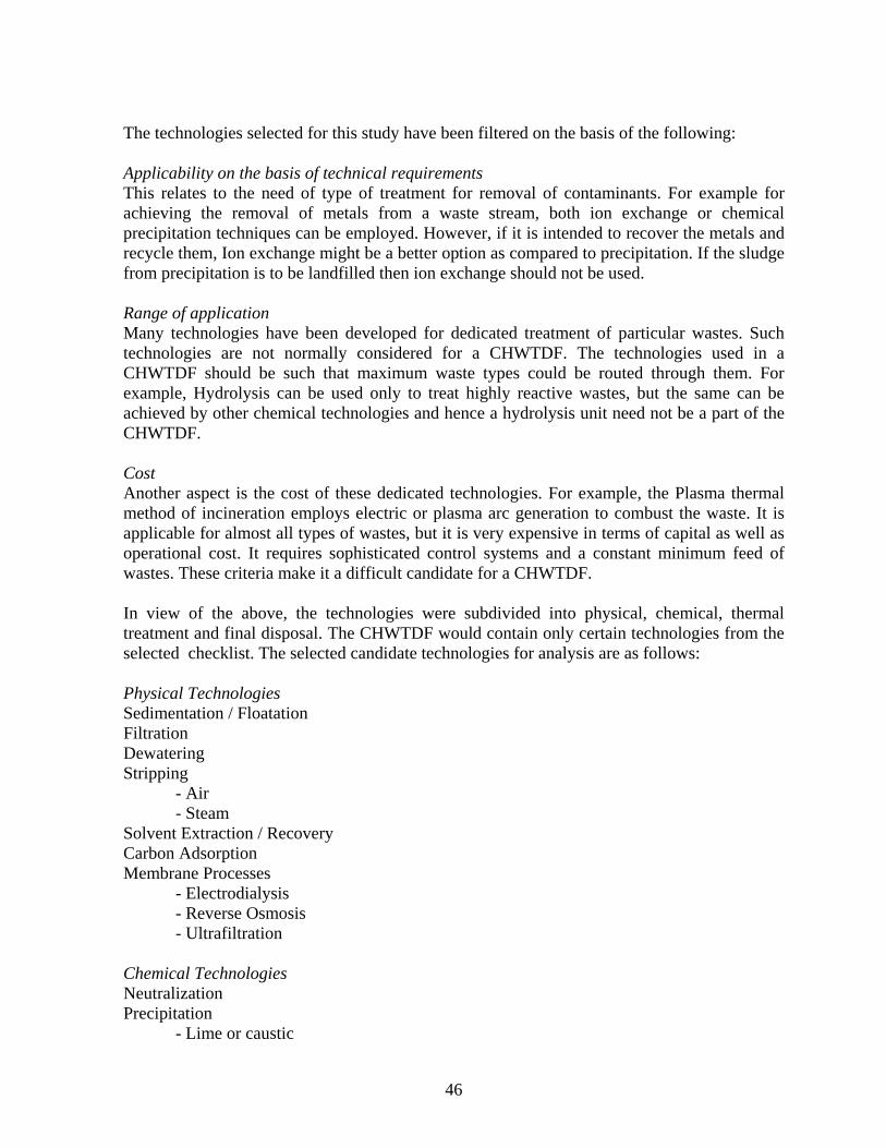
46
The technologies selected for this study have been filtered on the basis of the following: Applicability on the basis of technical requirements This relates to the need of type of treatment for removal of contaminants. For example for achieving the removal of metals from a waste stream, both ion exchange or chemical precipitation techniques can be employed. However, if it is intended to recover the metals and recycle them, Ion exchange might be a better option as compared to precipitation. If the sludge from precipitation is to be landfilled then ion exchange should not be used. Range of application Many technologies have been developed for dedicated treatment of particular wastes. Such technologies are not normally considered for a CHWTDF. The technologies used in a CHWTDF should be such that maximum waste types could be routed through them. For example, Hydrolysis can be used only to treat highly reactive wastes, but the same can be achieved by other chemical technologies and hence a hydrolysis unit need not be a part of the CHWTDF. Cost Another aspect is the cost of these dedicated technologies. For example, the Plasma thermal method of incineration employs electric or plasma arc generation to combust the waste. It is applicable for almost all types of wastes, but it is very expensive in terms of capital as well as operational cost. It requires sophisticated control systems and a constant minimum feed of wastes. These criteria make it a difficult candidate for a CHWTDF. In view of the above, the technologies were subdivided into physical, chemical, thermal treatment and final disposal. The CHWTDF would contain only certain technologies from the selected checklist. The selected candidate technologies for analysis are as follows: Physical Technologies Sedimentation / Floatation Filtration Dewatering Stripping - Air - Steam Solvent Extraction / Recovery Carbon Adsorption Membrane Processes - Electrodialysis - Reverse Osmosis - Ultrafiltration Chemical Technologies Neutralization Precipitation - Lime or caustic

47
- Sulfide Chromium VI reduction Cyanide Oxidation Ion Exchange Macroreticular Cationic / Anionic Thermal Technologies Rotary Kiln (high temperature) Liquid Injection (high temperature) Fluidized Bed (high temperature) Steam (Industrial) Boilers (low temperature) Wet Air Oxidation (low temperature) Pyrolysis (high temperature) Final Disposal Chemical Stabilisation Secure Landfill Biological systems are one of the widely used conventional wastewater treatment systems. Recent studies also indicate a high amount of treatability potential of these systems of toxics. However, these systems work better for dedicated individual treatment systems. The primary reason is that the feed needs to be consistent in characteristics and once the bacteria get acclimatised the feed load cannot be varied much rapidly. Secondly, land requirement is high for biological systems. In the case of a CHWTDF, the nature and amount of contaminants in feed would change considerably and hence it is assumed that biological systems are not a practically viable long-term option for a CHWTDF. Treatment Technologies Sedimentation / Floatation: A solid-liquid phase separation technology based on simple gravity settling principle. This process is used to settle solids when suspended particulate is high in the wastewater. Capital cost is a function of the tank volume or height. Operating cost is a function of the pumping of feed and sludge. Power requirement for raker arm would be additional costs. In the context of CHWTDF, sedimentation can be used after chemical precipitation of metal bearing wastewater to separate metal bearing sludge and clear effluent. Industry effluents which have high suspended solids could also be sent to sedimentation to remove inorganic SS prior to metal recovery or solvent recovery. It would be preferred to employ a skimming mechanism to remove floating organics, oils etc. which will not settle but contaminate the supernatant. These skimmings could either be sent to the skimmed stream from floatation unit to be incinerated. In a CHWTDF, sedimentation should be run on batch process based on the type of contaminants in the effluents alongwith SS. The primary reason for this is that the sludge settled in the sedimentation would have the contaminants (e.g. metals, pesticides) and the decision of routing this sludge, either to dewatering, incineration or chemical stabilisation would highly depend on the constituents present.
48
Floatation is employed with the aid of air bubbles to separate light organics like oils, grease fat etc. Floatation is employed in various modes like with and without recirculation, with online air injection / diffused aeration. The basic principle of floatation being buoyancy addition to the light organics to separate them from Both floatation and sedimentation are essential unit processes in a CHWTDF for phase separation and polishing. It is impractical to have separate units for floatation and sedimentation. Instead it is possible to integrate both the unit operations into a single operation so as to optimise. Both processes would have to be run as batch processes as per the requirement. Figure 4.1 presents the dual structuring of such a unit. The sedimentation and floatation operations could be separated by an intermediate cleaning to prevent cross contamination.
Figure 4.1 Sedimentation / Floatation Unit
Filtration This entails filtering the effluent to remove suspended matter, dissolved solids etc. by using a media which can retain the removables. Filtration techniques in conventional treatment normally employ gravity sand filtration, pressure filtration etc. Filtration would be required to further clarify the effluents from sedimentation, or direct waste streams could be fed for filtration. Filtration is particularly useful to remove solids from liquid wastes which are to be incinerated. Conventional sand filtration like sand bed filtration cannot be employed in a CHWTDF due to large hydraulic and solid loadings which would require more backwashing and would result in

49
shorter filter runs. Moreover the backwash will have sand alongwith the solids, which again would need separation. Solvent Extraction / Recovery by Supercritical Fluid Oxidation (SCF) This technology is based on the theory of dissolving solvents in a fluid at critical point (point at which the temperature and pressure is such that the fluid exhibits densities of liquid but diffusivities and viscosities of a gas). The mass transfer rates are enhanced because of reduced viscosity and diffusivity of the solvents at the critical point. This technique can preferentially separate solvents in various fluids. The common fluids used as SCF are Water, Ammonia, Benzene, Toulene and Carbon dioxide. If water is used the solvents are destructed and cannot be recovered. They form products like CO2, Cl, NO3 and PO4, based on the initial compounds present. The recoverability of a solvent is indicated by the distribution coefficient K. For example, a value of 4 indicates that atleast 4 kg of solvent laden wastewater feed is necessary to recover 1 kg of the solvent. The common requirement for an efficient SCF with water (SCWO) as the fluid is that the aqueous feed should have between 0 to 20% of organic solvent by weight. Particle size is important in an SCF and the solids present should not be more than 100 um in diameter. Normally, for SCWO, at the critical point as the solubility of organic solvents increases, inorganic solubility decreases which is desired so that the inorganic salts and metals in the waste feed do not enter the solvent phase. Inorganic solids removal is a post treatment requirement for this technology. Solvent Stripping This involves two commonly used technologies viz. Air stripping and Steam stripping. The basic principle is the same, that is the solvent streams are fed to a packed column and washed with counter current air flow in the first case and steam in the latter. Air Stripping – This technique is normally suitable for liquid streams with volatile organics lower than 200 mg/L in the feed. The type of air stripping units could be packed towers, Tray towers, spray towers and Diffused/mechanical aeration. The stripping of a solvent is a function of the stripping factor, which is calculated from the mass transfer rates and Henry’s constant. Capital costs of an Air stripping unit are a function of the tower volume. The operational costs are dependent on the air supply equipment, emission control and other pumping. Pretreatment might be required if the wastewater contains high suspended solids and salts. The suspended matter could be removed by simple sedimentation or filtration.

50
Post treatment includes controlling the air emissions. If the air stream contains high organics, the same may be passed through a Carbon adsorption unit to remove the same before release to the atmosphere. The organics can be biodegraded or incinerated after carbon regeneration. Risk / exposure hazard exists if the tower is open type. If packed tower is used risk is considerably reduced. In the case of air stripping, risk however is not a major issue. Steam Stripping – Steam stripping employs steam to forcibly remove solvents whose stripping factor is low and cannot be removed by simple air contact. Steam stripping can take higher loadings in terms of concentration of volatile solvents. Two primary factors govern the design rationale of a steam stripping tower, viz. strippability of organics and formation of a separable organic phase. Generally, as a thumb rule all the VOCs which are analysed by gas chromatography can be steam stripped. Types of steam stripping consists of random packed, valve trays or sieve trays. The process could be enhanced by generating vacuum in the tower. Again here, the pretreatment involves removal of inorganic salts (which suppress the stripping factor of the VOCs). Secondly, a consistent flow to the steam stripper should be maintained to economise and ensure proper removal. Thus it might be necessary to use a preequalisation tank before feeding the wastewater. Capital cost is a function of the reactor volume and the boiler requirements for steam generation. Operational costs are governed by steam generation and vacuum compressor power requirements. Dewatering Dewatering as the name suggests involves removal of water / moisture from the sludges before further treatment. A typical example is of chemical precipitation sludge from a thickener which has substantial moisture. This sludge should not be landfilled as it is, since the leachate generation rate could be enhanced in the landfill due to this inherent water. Dewatering systems can be classified on the basis of the principle used:
♦ Natural: Sludge drying beds, lagoons. ♦ Mechanical: Filtration, Centrifugation
The requirement of each is justified on the basis of the sludge types and the principle required to dewater the sludge. For example the water retained in the sludge matrix could be free water or inherent water or floc water or particle water. Each can be removed differently. When considering a dedicated treatment for a single industry the waste, it might be desirable to compare the various methods and decide the best for the particular waste type. However the best suited technique for a CHWTDF would be mechanical dewatering. The primary reason is that it has a higher range of application to most of the sludge types. Mechanical dewatering

51
includes centrifuges, pressure filtration, vacuum drum filtration and belt press. Belt press dewatering would be the most common option for a CHWTDF, which can be widely used. Addition of polymers might be necessary for certain types of sludges. A consistency of 50 to 60% can be achieved by belt press dewatering. Carbon Adsorption Carbon adsorption is best suited for soluble organic compounds, branched chain organics, double-triple bonded Carbon saturated organics. The principle is preferential attachment of the adsorbate to the surface of the adsorbent due to electrostatic forces. Activated granular carbon is normally used as a medium for the adsorption. Carbon adsorption can remove Arsenic upto low concentrations of less than 0.5 mg/L, and Copper upto 200 mg/L. Low traces of mercury can also be removed. Suspended solids normally inhibit the operation of adsorption. SS can be removed by filtration, otherwise upflow adsorption reactor may be used to achieve expanded bed adsorption. Capital cost of a carbon adsorption column is a function of the volume and height of the column. Operating cost is mainly on pumping and regeneration of carbon. Membrane Processes Membrane processes are based on preferential separation of material by diffusion of solvent through a semi permeable membrane. Of the conventional membrane processes, electrodialysis, reverse Osmosis and ultrafiltration are the most commonly used technologies for hazardous waste treatment. Electrodialysis involves employing the aid of applying electrical voltage charges across the reactor so as to selectively separate charged particles. This technique is effectively used for treating metal laden wastewaters. Since the driving force here is not pressure, presence of SS does not largely affect the efficiency of the system, however SS can form complexes and bonds with the metal and inhibit easy movement of the metal ions (cations) to the opposite electrodes. Total dissolved solids should be less than 500 mg/L to achieve a maximum treatment efficiency of about 80-90%. Reverse Omosis (RO) is used to separate salts and solvents using the osmotic pressure. Salt removal is more prominent than solvent separation in RO, primarily due to the typical membrane characteristics. Suspended solids however, inhibit the Ro process considerably and there is a need to maintain them at a minimum for efficient operation. Normally the total dissolved solids for RO should be lower than 50,000 mg/L and the suspended particulate should be less than 100 mg/L. Pressure is an important operating parameter in the case of RO.

52
Ultrafiltration is employed to separate organics and colloidal macromolecules from the wastewater. The principle used is of selective diffusivity of materials through the membrane.. For electrodialysis and reverse osmosis, oil removal is normally necessary prior to operation to avoid adsorbing sites for metals and clogging of the membranes, respectively. Temperature of the wastewater is important in all the membrane operations as it affects the diffusivities, osmotic pressures of the solutes and solvents and the performance of the membranes. Normally the membrane separation should be carried out at normal room temperatures. pH adjustment also is necessary in many cases, especially for RO and electrodialysis to avoid formation of unwanted complexes and compounds of metal during operation. Neutralisation This refers to neutralisation of acidity or alkalinity to maintain a pH of 7 in the wastewaters. This unit is necessary since pH an important parameter for many specific technologies and it necessary to render the acidity and alkalinity of the wastes neutral so as to ease the later processes. Neutralisation tank consists of a mixing tank with diffused aeration mixing. The capital cost is a function of the tank volume and operational costs depend on the pumping and aeration requirements. Chemical Precipitation This is the major technique to remove metals from wastewater. Barring Cr VI and Cyanides which need to be reduced and oxidised respectively, before precipitation, most of the other metal wastewater can be directly fed to the precipitation tank. The precipitation can be brought out either by use of lime or sulphide. Normally metal sulphides are less soluble than their hydroxides and hence it is easier to separate them to a large extent. However, metal sulphides which are landfilled as sludge pose a significant problem of H2S and sulphur in leachates, which is not of concern in hydroxides. Specific metal removal systems are given below: Arsenic : for high concentrations in wastewater, sulfide precipitation is used and the operating pH is 6-7. Cadmium : Ferric hydroxides precipitate cadmium at pH 6.5 to 8.5. Cadmium precipitation poses problems in the presence of Cyanide. Copper : Precipitates at an alkaline pH Sulphates, Cyanide and Ammonia should be removed for preventing complex formation and better efficiency. Iron : Conversion from ferrous to ferric and then precipitation of ferric hydroxide.

53
Lead : If soda ash is used precipitates as carbonate at pH 9.5. If lime is used then precipitates at pH 11.5 as hydroxide. Sulphide precipitation is possible with Na2S at a pH range of 7.5 to 8.5. Mercury : Iron co-precipitation is the best method for Iron precipitation. Sulphide or alum can also be used. However due to the low melting point distillation is the best method for removal and recovery. Nickel : Lime precipitation at pH 9-11. If present in high concentrations, Ion exchange or Evaporation for recovery can be used. Zinc : Lime or caustic can be used at pH 11. Sulphates should be removed before precipitation. Chrome Reduction To be precipitated, hexavalent chromium needs to be reduced to trivalent chromium. Sulphur dioxide or ferrous sulphate or metabisulphites are used to achieve this reduction. The pH for reduction should be acidic around 3. Cost is a function of chemical requirement, and pumping. Cyanide Oxidation Cyanide oxidation is normally carried out with chlorine or hypochlorite which liberates CNCl which is a toxic gas. This gas is then subjected to caustic treatment within the same tank to form nitrogen and carbon dioxide as final end products. Cost is a function of chemical requirement, and pumping. Ion Exchange Ion exchange involves use of resin beds over which the wastewater is passed. The resin beds selectively capture certain contaminants. Resins exist which can capture cations or anions and even organics / solvents (macroreticular resins) upto an extent. Pre treatment involves removal of Oil and grease, suspended solids. Both these parameters decrease the contact between the resins and the contaminants to be removed. Capital cost involves reactor and peripherals, whereas operational cost involves resin regeneration, pumping etc. Thermal Treatment Thermal treatment is a widely applicable unit operation for destructing various contaminants. The requirement of Incineration is based on the quantity of the incinerable waste and their incinerability which is calculated as below:

54
I = C + (a/H) Where, C = concentration of contaminant (%) a = dimensionless constant = 100 Kcal /g H = Heating value of the waste contaminant Kcal / g The higher the incinerability the more difficulty in incinerating the contaminant. The DRE should be calculated for the contaminant with the maximum incinerability index and it should not be less than 99.9999%. For example, halogenated solvents require a temperature above 1100 ºC whereas, non halogenated solvents require a temperature of at or below 1000 ºC. The selection of the actual type of thermal system can be based on various factors, such as the properties of the wastes, calorific heat values. Table 4.15 presents the applicability of various type of incinerators according to the waste types and form.
Table 4.15 Applicability of Incinerator Systems Thermal Technology
Cyanides Halogenated solvents
Non halogenated solvents
Aq with metals / inorganics
Aq. With organics
Oil and grease
Liquid Injection 650 to 1650 ºC
1 1 1 1
Rotary Kilns* 800 to 1650 ºC
1 1 1 1
Fluidised Beds* 750 to 900 ºC
1 1 1
Steam Boiler 500 to 700 ºC
1 1
Wet Oxidation 400 to 500 ºC
2 1 2 1
Pyrolysis 1 2 1 Source: Brunner et al (1993) Note: the numbers indicates the preference in the technology (1 indicates higher preference) • accepts both liquids and sludges Brunner (1993) specifies some of the important assumptions necessary in designing incinerator systems, viz.
• All hydrogen present converts to water vapour • All chlorides or fluorides convert to hydrogen chloride or hydrogen fluoride • All carbon converts to carbon dioxide • All sulphur present converts to sulphur dioxide • Alkali metals convert to hydroxides

55
• Non alkali metals completely oxidise, e.g. copper to cupric oxide • All nitrogen from waste fuel or air will take the form of Nitrogen as N2
Thermal systems due to the nature of the operations, hazards involved and the posibility of toxic emissions pose a high risk to the environment surrounding the site and hence require special public acceptance criteria. Referring to Table 4.5, it is necessary to provide air emissions control equipment so as to comply with the specified standards. Control systems include wet scrubbers, bag filters Stabilisation / Solidification Prior to the final disposal in landfills chemical stabilisation is an important step. The nature and choice of pretreatment required is highly dependent on the traces of contaminants present in the waste to be landfilled and their effects on the landfill liners, leachability, toxicity etc. Stabilisation attempts to treat these trace contaminants to render them ineffective before landfilling. The underlying principle here is that if the metals or toxics can be rendered a state in which they occur naturally, then the stabilisation would be more appropriate. For example, since zinc is naturally found in zinc phosphate ores, precipitating zinc as zinc phosphate would be the best stabilisation (La Grega, 1994). Sometimes stabilisation alone is not enough to make the waste safe for landfilling and solidification is used to physically encapsulate or integrate a matrix of a binder such as cement, lime etc. The resultant matrix is a hardened mass of wastes alongwith the binder, which can be safely landfilled. Important design considerations are volume generated of solidified waste per ton of original waste, surface area available for leachate. Capital cost involves mixing equipment and tanks for waste binder mixing. Operational costs involve power requirements, binder costs etc. Secure Landfill This is an important disposal technology widely used for final disposal of all untreated / treated wastes. La Grega et al (1994) defines landfill as a system designed and constructed to contain discarded waste so as to minimize the release of contaminants to the environment. The significant issues in a landfill design are:
• Volume requirements based on estimations of total residue generation from a treatment facility.
• Waste-Waste Compatibility • Landfill cover design • Leachate control

56
4.1.6 Cost Estimations and Assumptions for Treatment and Disposal Estimation of cost is the primary issue in selection of technology in a CHWTDF. The technology cost is assumed to be consisting of two components viz. Capital and Operating costs. Table 4.16 presents the technology-wise criteria affecting the capital and operating costs and the estimates for the same.
Table 4.16 Cost Estimations of selected technologies
Capital Cost Operating / Maintenance Cost Technology Criteria / Components
Estimate Million Baht
Criteria / Components Estimate Baht per ton or m3
Relative Cost factor
Sedimentation / Floatation
Tank Volume, Construction
5.15 / 19.45 Flow Pumps & aeration equipment
30
0.61
Neutralization Tank construction, Piping, Pumps
4.86
Flow, Pumping, Aeration, Chemicals
7
0.14
Filtration Filter volume, Media wieght Construction
4.62
Flow, Pumps & other equipment
17
0.34
SCF Reactor Volume, Equipment
500 a
Flow, solvent concentration, temperature, Pumps & other equipment
2500 a
51.5
Dewatering Equipment 11.85 Sludge Flow Pumps & other equipment
170
3.4
Carbon Adsorption
Column Height Media
8 a
Flow, concentration Pumps & other equipment
35 a
0.71
RO 13 a 100 a 2 UF 13 a 100 a 2 ED
Flow, Module, Piping, equipment
13 a
Flow, Pumping, membranes
100 a 2 Chemical Precipitation Incl. Cr, CN)
Reactor Volume, 30
Flow, Pumping equipment, Chemicals
12
0.24
Ion exchange Reactor bed Equipment
20 a Flow, pumps, backwashing
50 a 1
Thermal Weight of waste, Equipment, Construction
700 Weight of waste, Secondary fuel, emission control, pumping
600
12.3
Landfill Land, Liners, 50 a Weight of waste, Hauling, Labour
1000 a 20
Stabilisation Reactor, Mixing equipment
18 Weight of waste, Chemicals, Labour
150
3
a – assumed values, 1 US $ = 35 Baht

57
Notes: • This table has been prepared on the basis of Ellis et al (1985) and NHWMP (1989) • Capital cost factors are based on cost curves of cost versus relevant criteria for the
technology NHWMP (1989) • The relative cost factor has been developed to compare unit treatment costs on the same
scale or basis. • Transportation costs are not included GENCO (1998) reports a general costing structure as follows:
Direct Landfill 4000 Baht per ton Stabilization and Landfill 5500 Baht per ton Organic Solid Waste Blending 7500 Baht per ton Organic Liquid Waste Blending 1500 Baht per ton Transport 625 Baht per ton
4.2 Conceptual Framework The technology selection for planning a CHWTDF can be subdivided at two levels, viz:
♦ Selection of technologies with regards to initial planning and design of the CHWTDF, ♦ Selection of appropriate technologies (existing within the CHWTDF) for treatment
various waste streams during the operational phase of the CHWTDF. The former involves technology requirements according to quantity and type of wastes expected, future estimations, techno-economic requirements, available land and other resources, etc. The scope for technology selection for basic designing a CHWTDF is very narrow. Apart from the essential unit operations like sedimentation, filtration, neutralisation, phase change etc., all other specific technologies have several alternatives, some are only pilot / bench tested (like SCF) and the rest are commercially available (ion exchange, RO, incineration etc.). The decision for these technologies rests on several intricate factors such as applicability, actual capital and operating costs. If an expensive technology is selected, although treatability will be high, the cost of treatment would also be very high and consequently the fee structure would be affected. Thus, the affordability and willingness to pay of the member industries also has to be taken into consideration. Secondly, for some technologies although several options exist, from the point of view of universal applicability in a CHWTDF, only a few alternatives exist. For example, for incineration systems, several technologies exist, as outlined in Table 4.15. However, a CHWTDF will essentially have all kinds of incinerable material (liquids, sludges, gases etc.) and only rotary kilns or fluidised beds would be the most applicable and appropriate technologies. Membrane technologies for example, are used for specific applications where the waste feed is consistent and the membrane system is designed specifically for the particular waste contaminant. It can also be used as a polishing unit. Ion exchange also is used as a specific technology for extracting heavy metals for recovery.

58
Thus, the main criteria in selecting technologies in the design of a CHWTDF are the universal applicability of the technology to all expected wastes and the costing. The latter involves optimal routing of incoming wastes through various available technologies in the CHWTDF so as to achieve desired treatment and detoxification of the wastes. This focuses mainly on the pretreatment, post-treatment requirement and treabilities of technologies, residue generation factors of the technologies, operational cost, management aspects like storage, inventory buildup etc. The planning approach has been started from the task from the waste inventory available for the mixed industrial wastes. Once the waste quantities and characteristics of all the waste streams are available, primary analysis would be to classify the wastes in terms of categories as specified in Table 4.3. The rules developed are based on various literatures and authors communication with consultants and facility operators. 4.2.1 Rationale for Waste Mixing / Segregation The objectives of waste segregation are:
♦ To reduce hazard due to mixing, if any (Waste-Waste compatibility) ♦ To achieve dedicated treatment of special wastes ♦ To avoid interference and adverse effects on other treatment processes due to presence
of any hindering waste type ♦ To achieve better control if material recovery is the objective of technology
Industrial processes produce mixed wastes and very often the waste streams that arrive in the CHWTDF will not be in the segregated form according to the ease of treatment. Composition of the waste stream is a function of the process it emanates from, the raw material inputs used and the efficiency of the process. For example, a particular waste stream from a tannery may have solvents, organics and heavy metals. If ion exchange were considered for metal removal, the organics would clog the resin beds. On the other hand if biological treatment were considered to remove the organics, then the metal content would interfere with the growth kinetics of the system. It is possible to segregate the organics stream from the solvents and heavy metal streams, if the same are generated by different processes in the industry. Doing so, would greatly ease the load off the CHWTDF and a better treatment is possible. On the other hand the mixed waste containing solvents and heavy metals can first be treated to remove the solvent by simple air stripping (air sparging) if the solvent volatilisation point is low, or the combined waste can be sent to chrome reduction / precipitation, the supernatant of which could be then sent for solvent extraction by SCF. Thus, waste segregation can be addressed on two levels:
♦ The industry is asked to segregate or mix certain streams prior to entry in CHWTDF ♦ The CHWTDF segregates the components in a waste streams by storage and
preferential treatment

59
The thumb rules for waste mixing / segregation are: Within industry
♦ Hazardous and non hazardous wastes should not be mixed ♦ If possible, isolate waste streams on the basis of contaminants (e.g. solvent, metal
streams) ♦ Do not mix two phases of wastes, e.g., if the waste is dry solid do not make it aqueous
Within CHWTDF (GENCO, 1998) ♦ On the basis of waste-waste compatibility (refer Table 4.17) ♦ Liquid streams could be segregated as follows:
Those not requiring any pretreatment (e.g. neutral wastes, low heavy metals and suspended solids)
Acidic wastes (with or without heavy metals) Acidic wastes with Phenol Acidic wastes with hexavalent chrome Acidic wastes with emulsified petroleum hydrocarbons Alkaline wastes with organics / oily wastes Alkaline wastes with cyanide
♦ Sludges with heavy metals ♦ Sludges with toxic organics The following waste segregation should be maintained so as to ensure achievement of certain specific treatments:
♦ Nickel and Cyanide streams should be separate – Nickel cyanide complex formed interferes with the chemical precipitation of Nickel.
♦ Cadmium and Cyanide should be separate – Cadmium does not effectively precipitate in the presence of cyanide
♦ In general, cyanide waste stream should be segregated from other heavy metal or general streams
♦ Hexavalent chromium stream should be segregated from the other metal streams ♦ Separate Halogenated and Non halogenated solvent streams or containers.

60
Table 4.17 Waste –Waste Compatibility (Source : La Grega et al, 1994) 1 2 3 10 11 17 21 24 30 31 32 33 104 105 1. Acids, minerals, nonoxidising
2. Acids, minerals oxidising
3. Acids organic
H
10. Caustics
H H H
11.Cyanides
GT GF
GT GF
GT GF
17. Halogenated Organics
H GT
H,F GT
H GF
H
21. Elemental metals, alkali and alkaline earth
GF H F
GF H F
GF H F
GF H
GF H
H E
24. Metals and metal compounds, toxic
S S S S H G
30. Peroxides and hydro peroxides, organic
H G
H E
H E GT
H E
H E
H G
H U H GT
H G
H E
31. Phenols and Cresols H H F
GF H
H HF GF H
32. Organophophates H GT
H GT
H E
H U H F GT
GT GF H
33. Sulphides, inorganic GT GF
HF GT
GT H GT
H F GT
104. Oxidising agents strong
H GT
H GT
H E GT
H GT
H F E
H G
H F
H F GT
H F GT
H F E
105. Reducing agents, strong
H GF
H F GT
H GF
H E
H E
GF H
GT GF H
H F E

61
H – heat, F – fire, G – innocuous gas generation, GT – toxic gas, GF – flammable gas, E – explosion, S – toxics solubilization, U – hazardous but unknown The above table has been developed on the basis of La Grega et al (1994), for the wastes applicable in the selected industries. The primary function of this data is in the decision of intermittant storage of wastes on arrival and during treatment. With reference to the selected industries, Oxidising mineral acids, toxic metal compounds can be stored together – they will only result in oxidation reactions if in contact. However, they should not be mixed since the metal stream is to be precipitated and metal oxides would require higher amount of chemicals to stabilise. Since cyanide normally exists as cyanide (and not its salt) in alkaline medium, cyanides could be stored with alkaline or caustic streams, in case of caustic mixing is allowed since after chlorine oxidation the resultant CNCl will have to be washed with caustic to form salts which can be precipitated and secure landfilled. Organic solvents, halogenated or otherwise, hydrocarbons and other organics could be stored together, without any hazard. The mixing should be done as given in section 4.2.1. Organic acidic streams (agrochemicals, drugs) and mineral acidic streams (metal plating, chemical) should not be mixed to avoid exothermic oxidation

62
4.2.2 Waste Generation Variance Factors To estimate the expected variance in the waste inventory it is necessary to consider several factors, which play a role in affecting the generation of Hazardous wastes and ascertain the change each might induce. As mentioned in section 4.1.4, various types of activities are involved in WM. The potential of each activity differs with the type of the industry, its size and the stringency of regulations prevailing in the region. Table 4.18 presents the basis of estimating the expected change in the waste generation. Table 4.18 should be generated over spans of 5, 10, 15 and 30 years. The reason being that the changes would be generally on the higher side in the first 10 years, but it is difficult to predict the changes after 10 years as they would be a function of the innovative technologies developed, type of waste minimisation methodology used. (e.g. process modification, equipment replacement) Sometimes, if material replacement is considered a hazardous waste constituent may be totally replaced with a non hazardous one in the future. For example, if chromium is replaced by Titanium in the Tanning industry then the hazardous Cr VI can be totally eliminated. Of course, such changes are more possible for large industries, which can afford the capital and operating expenses of the new system. Thus the size of the industries should also be considered while estimating the variation factors in the hazardous waste generated. Since the various WM options affect various waste contaminants and streams differently, it is necessary to develop the factors for the major classes of the waste types. For example, for a metal plating industry, only volume of waste and metal content would be affected due to rinsewater recovery and recycle, organics in the waste would not be largely affected. Thus, the waste generation variance factors should be developed on the basis of size, type of industry, specific contaminants, for each factor that might affect the waste generation potential of an industry and over time spans totaling the estimated life of the CHWTDF. For example, pretreatment by industries does not substantially reduce the waste volume necessarily, but the organic (solvents) and metals could be reduced due to recycling and reuse. Pollution prevention activities alongwith material recovery focus on reduction of waste volume, in terms of flow and load, and hence the volume reduction could be assumed marginally higher than others. It could be safely assumed that reduction in production or expansion of industries would more or less equally decrease or increase all the parameters. Inclusion of new industries on the other hand would affect the flow volume of wastes generated more substantially than the other parameters. Table 4.18 developed below presents the general format of the development of the factors.

63
Table 4.18 Waste Generation Variance Factors
Volume (flow / quantity)
Heavy metals Organics Factor / Criteria affecting
% / 15 years % / 15 years % / 15 years Pollution prevention measures by industries
-1
-0.75
-0.5
Change in pollution load due to pre-treatment by industries
-1
-2
-3
Reduction in production levels due to competition
-2
-2
-2
Closing down of industries due to poor performance
-0.5
-0.5
-0.5
Expansion of existing industries
+3
+3
+3
Inclusion of new industrial units
+4
+3
+3
Total + 2.5 + 0.25 0 + indicates increase - indicates decrease Thus the engineering design of the selected technologies should consider the modification according to the factors and the parameters should be changed accordingly. 4.2.3 Selection of Unit Operations Unit Operations can be divided into two categories based on the functions they serve, viz: Essential unit operations complementary to treatment technologies These unit operations are not treatment technologies by themselves as regards hazardous waste management but are required to complement the dedicated treatment technologies. Typical examples of such technologies would include sedimentation, filtration or sludge dewatering, phase changes from tarry slurry to pumpable liquids. It is interesting to note here that in conventional waste treatment these would be specific technologies since parameters like suspended solids, dissolved solids, moisture are significant parameters which need to be removed from the waste matrix before disposal / discharge. However, in hazardous waste management, these operations would form the pre and post treatment requirements for specific technologies like incineration, ion exchange, stabilisation etc. Such unit operations hence would be necessary to achieve the desired performance of the dedicated technologies like solvent extraction, metal recovery etc. Dedicated technologies for hazardous contaminant removal / reduction / destruction These operations would be the technologies that, remove, reduce or destroy the hazardous contaminant in the waste streams, so that the same can be disposed safely. This category

64
includes operations like thermal treatment, metal precipitation, solvent extraction / recovery, ion exchange, stabilisation etc. Decision on selection of these technologies is a function of the objectives desired. For example, ion exchange and metal precipitation, both could be potential technologies for treating metal laden wastewater. The final selection would depend on whether recovery is desired or treatment / disposal is desired. The former again would be a function of the type of metal in the waste and the quantity. (for example an achievable strength of 6000 ppm of chromium in the precipitate sludge would not be attractive for metal recovery but higher concentrations such as 20,000 ppm etc. would be candidate wastewaters for metal recovery, especially when the wastestreams are single metal streams) The criteria necessary to select each type of the above mentioned unit processes in the basic design of the CHWTDF involves the following: A] For Essential unit operations complementary to treatment technologies The selection criteria for these unit processes is more or less governed by the requirement of the specific technologies. The primary reason is that these unit processes are used normally for pre or post treatment of the specific technologies and hence the requirements of these technologies control the need and choice of the essential unit operations. For example, sedimentation is essential to separate precipitated metals from wastewater after chemical precipitation or dewatering is recommended before sludge is sent to a thermal treatment unit.. The common unit operations under this category would be sedimentation, floatation, filtration, neutralisation, dewatering, phase change from slurry to pumpable liquids etc. B] Dedicated technologies for hazardous contaminant removal / reduction / destruction 1. Quantity of the waste for the treatment of which the unit operation is considered The capital cost of a unit operation can be justified only if sufficient minimum amount of waste quantity (in terms of flow and concentration) that it treats is available. If the same waste can be treated with another technology which is of lower cost and accepts low quantities then that unit operation should be selected. 2. Quality or characteristics of the waste for the treatment of which the unit operation is considered Most of the technologies require certain minimum concentrations for justifying the need of the unit operation. For example, super critical fluid oxidation requires that the minimum solvent concentrations be between 0 to 20% by weight to be able to recover the same. Thus based on the total inventory (including factors for future increase or decrease) technologies can be compared as per the requirement of the concentrations of contaminants.

65
3. Technology applicability and modifications Direct technologies which are conventionally used for individual industrial treatment may not be as is applicable in the case of CHWTDFs. As mentioned earlier the technologies selected for a CHWTDF should be multi-applicable so as to optimise. It is necessary and possible, based on certain requirements, to modify conventional technologies so as to make them usable for multi purpose applications. For example, consider the requirement of sedimentation and floatation tanks. Sedimentation tank is necessary to settle precipitated metals or removal simple suspended solids removal. Floatation tank is necessary to separate oil and grease in mixed waste streams. The basic design of both the tanks is similar, the only difference being in the flow direction and retrieval of various separated phases. It is possible, as shown in Figure 4.1 to combine both these functions into one tank which can be operated as a batch process for each type of system. The relevant equipment can be operated for each type. Thus, if the amount of flow expected for sedimentation is very low as compared to the floatation unit then the need to construct a separate sedimentation tank can be eliminated by such a combination. A special mention must be made for Thermal treatment technologies. Referring to Table 4.15, it is not practically possible to select separate technologies for thermal treatment and construct more than one incineration systems. So consequently, the best technology would be the one which can incorporate most of the waste forms and contaminants. Rotary kiln and Fluidised Beds have shown considerable stability in this regard. (La Grega et al, 1994 and Brunner, 1993). Since a central treatment facility accepting wastes from the varied industrial sectors will consist of most of the waste types and forms, the most practical solution would be to either construct a rotary kiln or a fluidised bed system. The criteria necessary to select each type of the above mentioned unit processes in the operational phase of the CHWTDF are described in section 4.2.4. 4.2.4 Rationale and Rules for Selection of Technologies in Unit Operations and Routing The technologies selected as candidate technologies have been studied on the basis of the following criteria or parameters. Criteria for Physico – chemical technologies
♦ Effectiveness / performance ♦ Cost (capital and O&M) ♦ Pretreatment requirements ♦ Post-treatment requirements ♦ Possibility of Material Recovery ♦ Flexibility in Operation ♦ Labour requirement ♦ Public Information and Consultation (PIC) i.e. public acceptance ♦ Risk or Hazard during operation

66
Criteria for Thermal technologies
♦ Treatability ♦ Cost (capital and O&M) ♦ Application range ♦ Pretreatment required ♦ Post-treatment required ♦ Secondary fuel requirements ♦ Labour ♦ Risk / hazard in operation
(PIC has not been included here because, in the case of thermal technologies almost all the technologies encounter resistance from the public). Criteria for Final Disposal
♦ Volume / weight consumed ♦ Land requirement
Prior to selection of technologies, the waste streams from the industrial inventory would have to be classified and categorised in the manner of waste segregation as given in section 4.2.1. The categorization could be on the basis of physical form, physical and chemical characteristics. For example the block below shows the classification of a typical tannery waste. Heavy metal laden stream – if wastewater form and pH is acidic, with heavy metals, then waste can be classified as Inorganic acidic heavy metal stream. If it contains only chromium VI, then it will be inorganic acidic Chrome bearing stream. Table 4.19 presents the decision matrix of Technologies / Unit Operations according to their applicability to various waste types. Table 4.19 Applicability of Treatment / Disposal Technologies to Specific Hazardous
Waste Contaminants / classes Technology Contaminant
SF F N SCF SS D C M P I T L ST
Oil and Grease H 0 0 0 0 M H L L M H 0 0 SS H H 0 0 0 H 0 0 M 0 L 0 0 Acidic / alkaline 0 0 H 0 0 0 0 0 0 0 0 0 0 Organics / BOD L L 0 0 0 L M 0 0 0 H 0 0 Phenol 0 0 0 H M 0 M L# 0 L H 0 0 Halogenated Solvents
0 0 0 H M 0 M L# 0 L H 0 0

67
Non Halogenated Solvents
0 0 0 H H 0 M L# 0 L H 0 0
Inorganic Sludges w/o Heavy Metals
0 0 H 0 0 H 0 0 0 0 0 H 0
Inorganic Sludges with Heavy Metals
0 0 H 0 0 H 0 0 H* H* L H H
Organic Sludges w/o heavy metals
0 0 0 0 0 H 0 0 0 0 H 0 0
Organic Sludges with heavy metals
0 0 0 0 0 H 0 0 0 0 H L H
Cr VI (aq) 0 0 H 0 0 0 0 0 H H* 0 0 0 Ni (aq) 0 0 H 0 0 0 0 L# H H* 0 0 0 Cu (aq) 0 0 H 0 0 0 0 L# H H* 0 0 0 Cd (aq) 0 0 H 0 0 0 0 L# H H* 0 0 0 As (aq) 0 0 H 0 0 0 0 L# H H* 0 0 0 CN (aq) 0 0 H 0 0 0 0 L# H H* 0 0 0 This matrix has been generated based on various literatures and the author’s communication with treatment facility operators and consultants. * Used for sequential metal recovery with sulphuric acid leaching and subsequent Ion Exchange technology, only for feed wastewaters with very high metal content (Freeman, 1990). # Only electrodialysis (ED) is used to separate metals (without other impurities) upto certain low concentrations. RO can concentrate divalent metals upto 10-20% solution. Solvent removal has been shown to be 97% efficient by Ro, only in certain cases like Dimethylpthalate and Napthelene. (La Grega et al, 1994) Legend: SF – Sedimentation / Floatation P – Chemical Precipitation F – Filtration I - Ion Exchange SS – Solvent Stripping (air / steam) T - Thermal D – Dewatering L – Secure Landfilling C – Carbon Adsorption ST – Chemical Stabilisation M – Membrane processes (ED, RO and UF) N - Neutralisation SCF – Supercritical Fluid Oxidation Note: The above matrix has been generated on the basis of relative weightages in terms of the best technologies available for treatment and disposal of a specific waste contaminant or class of wastes. The weights have been given on a scale of low, medium and high with the Best technology given the highest score i.e. High. For the Excel spreadsheet, the score allotted to these levels are 1,2,3. 0 indicates inapplicability of the technology for that contaminant. It is important to note here that, unlike as in Ellis et al (1985) the fact that technologies other than the dedicated ones would also contribute to partial removal of contaminants, however, such technologies cannot be considered as specific choices of treatment for that particular contaminant. For example, some oil and grease might be removed in filtration or certain BOD

68
will be removed in Sedimentation, but these cannot be termed as applicable technologies for these contaminants. The rationales and rules for selection of technologies and specific routes for particular waste types during operation of the CHWTDF are given below: 4.2.4.1 On the basis of quantity, quality and form of wastes Segregated Organic Waste streams – Should be directly taken to Thermal treatment. Moisture content should be minimum as far as possible and hence the wastewater may be routed through Dewatering system prior to Incineration. High Suspended Solids Stream – Should be sent to sedimentation if settleability of solids is high, i.e. if particles contain inorganics / sand / macromolecules etc. If settleability is low, should be sent to pressure filtration. If inorganic SS in low concentrations are present which can be precipitated alongwith with other contaminants like metals, stream should be sent to Chemical Precipitation. Acidic / Alkaline Streams These streams could be sent directly to neutralisation unit and thereafter to chemical precipitation tank Sometimes, the acidic or alkaline streams may be reused for acidic de-emulsification Segregated Phenol bearing streams – For high concentrations of phenol, where recovery is intended, streams should be sent to SCF. For low to medium concentrations and recovery not intended, streams should be sent to thermal treatment. Segregated Chromium VI streams – Should be sent directly to chrome reduction and then routed to Chemical Precipitation. If very high and recoverable concentrations exist, Cr VI can be reduced and routed to Ion Exchange for recovery. Segregated Cyanide streams – Should be sent directly to Chemical Precipitation, for cyanide oxidation with chlorine (batch process). Solvent streams (halogenated and non halogenated) – If the concentrations are high (> 20%) and the specific solvents are adsorbable on activated carbon, activated carbon adsorption column or strippable in Air or Steam stripping then concentration should be reduced to 20% by weight by these technologies and then routed to technologies like SCF for recovery. If the solvent concentrations are below 20% by weight, and recovery is desired, SCF should be selected. If recovery is not intended, stream should be sent to thermal treatment.

69
Inorganic sludges without heavy metals – Should be sent directly to Landfilling. Dewatering may be necessary based on the moisture content to reduce volume. Inorganic sludges with heavy metals – Should be sent to dewatering prior to any treatment if moisture is high. For very high metal concentrations (attractive for recovery) in the inorganic sludge, leaching with sulphuric acid to bring metals in the liquid form and then using preferential Ion Exchange to recover the metals could be employed (Freeman., 1990). Chemical Stabilisation with sodium sulphide may be required for Hg, Final disposal should be landfill. Organic Sludges without Heavy metals – Dewatering should be used for high moisture content Dewatered sludge could be sent to incineration Organic sludges are not landfilled Organic Sludges with Heavy metals – Dewatering should be used for high moisture content (>30%) Dewatered sludge could be subjected to leaching out of metal streams for recovery in case of high metal content, Residue should be incinerated Waste streams with other Heavy metals (Ni, Cu, Cd, As) – Should be sent to chemical precipitation Precipitate should be settled / clarified, dewatered and then landfilled with or without stabilisation. On the basis of Technology Sedimentation / Floatation Should be operated in batch process if mixed settled sludge is not desired If settled sludge contains inorganics alone, should be sent to Landfilling enroute Dewatering for increasing the consistency. If settled solids contain heavy metals, check concentration of heavy metals. Decide recoverability, If metals are recoverable use sulphuric acid leaching and Ion exchange. If metal concentrations are lower, send to Dewatering unit and then to landfill. Chemical Stabilisation may be required for Hg, Skimmings of oil and grease could be sent directly to thermal incineration or could be recovered for secondary use Neutralisation Should be used to neutralise acidic / alkaline wastewaters and sludges / slurries (after phase change) This should be a batch process

70
After neutralisation stream should be routed to Chemical precipitation unit Filtration Should be used only to polish streams (for SS removal) from Chemical Precipitation, Dewatering, Carbon Adsorption No direct waste stream should be allowed directly for filtration due to possible hindrance due to: High Oil and Grease (will decrease filter run and require higher backwashing periods) High organics which will clog the filter media Filtrate should be sent to Ion exchange or RO for polishing and discharged to water body Filtered solids should be sent to Chemical Precipitation unit or dewatering unit and landfilled SCF Criteria for waste feed to SCF: - Ability of waste to be pressurized Requires amount of SS, oil and grease, viscosities and particle size (<100 µm) to be low - To be cost effective, feed should not contain organic solvents more than 20% by weight Washed Inorganic solids from the reactor should be separated by pressure filtration and the supernatant should be routed to Chemical Precipitation Solvent Stripping Air Stripping should be used only if VOC concentration is within 200 mg/L The stripping factor should be calculated based on R = H`*(Qa/Qw) H` = Henry’s gas constant Qa = Air flow rate (m3/s) Qw = Water flow rate R should be greater than 1 for stripping to occur Air emissions should be checked for organics and if volatile organics is high then air stream should be routed to Carbon adsorption before release to atmosphere. Otherwise, air stream should be fed to the thermal system for incineration. Dewatering For dewatering sludge should be pumpable If dewaterability is low, addition of polymer might be necessary Carbon Adsorption Oil and grease waste streams upto 10 mg/L should be directly routed to this unit (Ellis et al, 1985). If suspended solids (which is not adsorbable) is high then Sedimentation should be used to settle suspended solids with or without coagulation. Filtration could be used if oil and grease is not high enough to clog filter media. Suspended solids should be less than 50 mg/L (Ellis et al, 1985) Phenol and solvent streams (low concentrations) could be routed to Carbon adsorption provided recovery and /or oxidation is not intended.

71
Membrane Processes ED Low concentration metal wastewaters without organics (normally from plating rinse waters) can be routed to electrodialysis for concentrating metal upto certain limits. Single pass can concentrate upto 30 – 60% and subsequent passes can concentrate upto 80% based on the metal ionization potential. TDS should be less than 5000 mg/L RO Low concentrations of metal wastewater streams and organic streams can be passed through RO for metal removal. UF Emulsified oily streams (pure) should be passed through UF for deemulsification. Certain organics within molecular weight cutoff of 500,000 can be separated. Dissolved solids should be less than 50,000 mg/L Suspended solids should be less than 100 mg/L – route waste stream to filtration to reduce SS. Chemical Precipitation Unoxidised Cyanide streams should not be allowed to this unit Unreduced chromium VI streams should not be allowed to this unit This unit should be operated in batch process. Since the precipitation of the metals is a function of pH and various metals will precipitate at various pH values, alongwith the requirement of the precipitating agent, process should be planned according to the sequential precipitation of metals. Arsenic should be removed by sulphide precipitation Cadmium should be removed by hydroxide precipitation Hydroxide precipitation of Iron requires removal of dissolved organics Mercury should be removed by sulphide precipitation Zinc should be removed by hydroxide precipitation Nickel should be removed by hydroxide precipitation For Copper, ammonia should be removed prior to precipitation (this can be achieved by simply raising the pH to 11 and aerating the wastewater to strip ammonia. Sludges from precipitation should be routed to dewatering before landfilling. Chemical Stabilisation is normally not necessary for precipitated metals. Ion Exchange Suspended solids should be low to avoid clogging of resin bed Oil and Grease can be retained only on macroreticular resin beds upto medium levels, however, for cation / anion exchangers oil and grease will interfere so it has to be minimum. This unit should be operated on batch process to allow preferential removal of different contaminants (as in Freeman, 1990)

72
Thermal Treatment Wastewater to be fed to the thermal system should be free of heavy metals so as to comply with the metal emission standards. Normally only solvents, organics should be present in the feed. Sludges to be fed should be dewatered suitably before feeding. When pure organic sludges are incinerated, emissions (CO2, water vapour) can normally be discharged to atmosphere If sulphur is present, alkali scrubbing should be employed If halogenated wastes are incinerated, gaseous residues will have hydrogen halides and free halogens, these gases should be neutralized with caustic. Caustic neutralisation streams can be routed to Chemical precipitation unit. Aqueous salt bearing waste should not be injected directly into the flame All ash from the incineration should be secure landfilled Chemical Stabilisation Unprecipitated metals and metals like Hg after dewatering should be stabilised chemically by sulphides, to reduce leachability, before landfilling Secure Landfill Waste should have minimum moisture before landfilling (< 20%) Inorganic sludges without heavy metals could be directly landfilled Inorganic sludges with heavy metals should be checked for chemical stabilisation The proposed framework is presented schematically showing all the possible routing options in Figure 4.2. An example of a closed loop for a particular waste stream is presented in Figure 4.3. 4.2.4.2 Management Aspects of a CHWTDF The planning of a CHWTDF involves several factors of importance such as: Waste storage The waste inventorisation from industries for a CHWTDF also includes a waste arrival plan, which specifies the type, quantity and frequency of waste supply from the industry to the CHWTDF. This scheduling has to be matched with the treatment sequences and appropriate intermediate storage (in lieu with the waste-waste compatibility and waste routing / technology sequencing). It is advisable to have sufficient number of tanks for storing and mixing different segregated waste streams. Waste and residue movement (pumping or solid loading) Since most of the systems work as batch processes, it is necessary to plan the movement of the feed waste, residues, air emissions so as to avoid conflict and undesirable mixing. Management of recovered contaminants If solvent or metal recovery is practiced the routing of the wastes after recovery has to be specified according to the agreement between the CHWTDF and the member industries.

73
4.2.5 Use of Analytical Hierarchy Process (AHP) for Technology Selection AHP is the process used for multi criteria decision making. When one alternative has to be selected out of n available alternatives, the process is very simple if only one criteria exists on the basis of which a decision has to be made. The alternative with the highest score would be the best. Problems arise when multiple criteria exist and different alternatives rate differently on the basis of each of these criteria. AHP uses the software ExpertChoice Ver. 9.0. The primary principle of the software is that it accepts criteria, alternatives which are to be based on the criteria and accepts weights from the user, which relate the preferability of alternatives with respect to various criteria and amongst the criteria. Based on the Analytical Hierarchy Process, Expertchoice, compares tangible factors with intangible factors, for example cost of a project and viability of a project. It performs, matrix calculations to arrive at a total score for each alternative. The one with the highest score is the best alternative within the given criteria. In this study AHP ExpertChoice has been used to compare technologies for certain unit processes, viz.
• Solvent Recovery • Thermal Methods
It can also be used for other unit operations is more than one conflicting alternatives exist. The criteria used for comparing these technologies are as presented in section 4.2.4. The main advantage of using AHP is that the software provides online sensitivity analysis which can be used to determine the technology to be used for certain waste streams during operation of the CHWTDF. The software provides a basis for changing the levels or importance of the criteria and presents the new ranking of technologies on the basis of best to worst, according to the changed criteria. A typical screen showing the structure of the model for selection of technology for Solvent Recovery has been presented in Figure 4.4.

74
Indicates decision point for technology selection based on rules
Figure 4.2 Schematic of Framework
AgrochemicalsHalogenated Solvent Stream A1Non-halogenated Solvent Stream A2Rinse water with Pesticides A3and Heavy MetalsToxic & Pesticide Sludge A4
Bulk Drug/Pharmaceuticals
Acidic Wastewater B2Solvent Wastewater B1
Toxic Organics Wastewater B3WWTP Sludges B4
ChemicalHeavy Metal Wastewater C1Acidic Wastewater C2Alkaline Wastewater C3
Non-halogenated Solvent Str. C5Halogenated Solvent Str. C4
Oily Wastewater C6Sludges C7
Metal FinishingOily Wastewater M1Acidic Wastewater with Hazardous Metals M2 without Hazardous Metals M3Alkaline Wastewater M4Heavy Metal Wastewater M5Solvent Wastewater M6
PetrochemicalEmulsified Oils Wastewater P1Non-emulsified Oils Wastewater P2Halogenated Sludges P3Non-halogenated Sludges P4Inorganic Sludges P5Heavy Metal Wastewater P6
TanneriesHeavy Metal Wastewater T1Organic Wastewater T2Heavy Metal Sludges T3Solvent Wastewater T4
Paper ManufacturingHalogenated Solvent Stream PP1Non-halogenated Solvent Stream PP2Acidic Wastewater PP3Alkaline Wastewater PP4Organic Sludges Toxic PP5
Sedimentation
Filtration
Floatation
Air StrippingSteam Stripping
SCF
Dewatering
Carbon Adsorption
ElectrodialysisROUF
Neutralization
SulfidePrecipitation
Lime, Alum, OHPrecipitation
ChromeReduction
Cyanide Oxidation
MacroReticularResin Bed
Cationic / AnionicResin Beds
RotaryKiln
FluidisedBed
ChemicalStabilisation
Solidification
SecureLandfill
Discharge toSewer
/ Water Body
PHYSICAL CHEMICAL THERMAL DISPOSAL
Leachate
AshVOC if notrecoveredin SCF

75
Figure 4.3 Schematic of a Closed Loop
Figure 4.4 A Typical Screen for AHP Structure for Solvent Recovery technology Selection
Example of a Closed Loop for a Waste Stream
Consider a Waste stream with low solids, high volatile organics, high non volatile organics and high amount of heavy metals
SS /SCF P C / Muf Discharge
T T
D ST L
Leachate
Waste Waste FeedFeed
Ash
Air emission control
Air emission control
Decision Point

76
Figure 4.5 Sensitivity Analysis Screen for Solvent Recovery Technology Selection
The screen for sensitivity analysis for the same has been presented in Figure 4.5. The criteria on the X-axis can be varied so as to generate different rankings of the technologies. The sensitivity analysis can be performed on the basis of comparison of all alternatives and all criteria, or two alternatives and all criteria or between two criteria for all alternatives. That is the flexibility available in the process is immense for detailed comparisons of various alternatives. The AHP model can be used for selection of technologies during the design of the CHWTDF as well as during the operation for optimal waste routing. 4.2.6 Development of Pricing Model for charging Member Industries Once the technologies have been selected on the basis of applicability, need and cost it is necessary to devise a scheme for charging the member industries for the waste treatment. The charging methodology depends on the following factors (HWMP, 1996): Ownership model of the CHWTDF - The possible ownership models which exist in practice, are Government, Private sector, user co-operative and combination of government and private. The payment structure would be different in each case. For example, in the Government owned model, it is possible to provide subsidies, rebates and achieve better policy objectives. At the same time, Government will be sharing the risk and hence that liability cost would not be burdened on the members as in case of privately owned facilities. In the privately owned models, the interest rates would be high for financing and risk sharing costs would be higher, but the treatment costs and efficiencies would be higher due to professional management.

77
Risks involved in operating the CHWTDF - Due to the nature of the hazardous wastes and the ownership models used, certain major risks would be involved in the construction and operation of a CHWTDF, which would add to the fee structure a risk cost. The following risks are expected: Waste supply risk This is refers to non-availability of adequate wastes (as estimated in the inventories) for treatment. Normally, treatment costs for lower than design waste volumes, would be high. The reasons for waste supply risk could be, individual pretreatment by industries, increased waste minimisation, waste recovery activities in the industries. Institutional Failure Risk In the case of privately owned or co-operative ownership, it is highly important that proper understanding exists between all members and parties involved, as regards acceptance of waste, costs incurred, liability involved, risk sharing etc. In the absence of such a memorandum of understanding, it may happen that the organisation developed to build, operate / own the treatment facility would not run efficiently and finally due to conflicts will have to be stopped from operating. This is termed as Institutional failure risk. Actual costs incurred in Treatment of Wastes – The treatment costs of the wastes would be the actual costs in terms of Baht per unit waste quantity to be treated. Waste Transportation Costs – Transportation costs are the costs incurred to ship the waste from the industry to the CHWTDF. It also includes the waste hauling and labour charges. Sometimes transportation risk (spillage, accidental release) is also included in certain models and certain fraction of the cost is allotted towards this risk. 4.2.6.1 Polluter Pays Principle (PPP) The principle of PPP, is that the industry must pay for the cost of disposing waste in an environmentally acceptable manner. Applying this principle to CHWTDF implies that all the costs be shared among the participating industries proportionate to the system capacity required to manage their specific hazardous wastes. Charge models developed for CETPs for conventional industrial treatment are based either on quantity method or load (combined) method. (Han, 1990 and HWMP, 1996) The quantity method is suitable for industrial estates with similar type of industries. The reason being that since the waste types and their concentrations do not vary significantly, and even if they do, it would be a function of the wastewater flow. For example, for a tannery industry if the production size is comparable and the flow volumes are similar, then the BOD or metal content would be comparable. Thus a fee based on total volume to be treated is the appropriate model for such schemes. On the other hand, for mixed type of industrial estates, the waste types differ in terms of waste contaminants and flows, thus making it unfair to base a fee on the basis of flow alone. In this

78
case, it is possible that a generator with low flow will have a high BOD or COD, requiring higher and costlier treatment, whereas a generator with high flow might be having a low BOD or COD, requiring lesser treatment cost. If both these industries are charged on the basis of flow alone, the latter would be unfairly charged a heavy fee. This would be risky to the organisational structure of the CETP. Hence in such cases a load based structure is adopted, which evens out the variation in the parameter concentrations and brings both generator on a comparable level. In the case of a CHWTDF, the scenario is totally different. As in the case of a CETP, the parameter of evaluation was the same, viz. BOD or COD, however, in the case of a CHWTDF, the parameters would vary according to the hazardous contaminants in the industry’s waste. Not all industries would have the same parameters. For example, a metal finishing industry or a tannery would have heavy metal bearing wastewater as the major contaminant. Whereas, a paper manufacturing industry would have solvent laden wastewater or an agrochemical industry would have toxic organics as the major component of its waste. Based on the proposed framework, it is seen that every waste stream (liquid and solid) from a industry takes a particular route in the overall treatment scheme. Thus, it undergoes certain treatment technologies and it bypasses the other. The charge should not only address the working costs incurred during treatment but other cost sharing such as:
♦ Capital Costs of Technologies taken by the waste streams of a particular industry ♦ Fraction of Capital costs of other technologies bypassed ♦ Operating costs (or treatment cost Baht per ton or m3 of waste) of technologies taken
by the waste stream of a particular industry ♦ Labour cost (also could be based on the route taken and the technologies used) ♦ Rebates or subsidies if recovered material will be sold by the CHWTDF operator
4.2.6.2 Proposed Pricing Model Required parameters to arrive at the fee to be charged include
• Total number of waste streams from the industry (solid and liquid) • Technology Route taken by each waste stream and the quantities in the feed as per the
criteria of the technology. • Cost Fraction for Risk Factor
Total cost to be incurred by a member industry would be calculated as follows: A] Cost for Stream 1 = (Unit cost of Technology 1) Baht / unit load * quantity of waste (as per the unit loading rate) + Unit cost of Technology 2) Baht / unit load * quantity of waste passing (after reduction in technology 1) +……. Technology n (as per the selection)

79
Similarly, B] Cost for Stream 2 = (Unit cost of Technology 3) Baht / unit load * quantity of waste (as per the unit loading rate) + Unit cost of Technology 4) Baht / unit load * quantity of waste passing (after reduction in technology 3) +……. Technology n (as per the selection) C] Miscellaneous cost = Constant fraction cost for unused technologies + Labour costs – Rebate for recovered streams where, Rebate for recovery = % recovered * cost for the technology used D] Risk factor cost = 0.5% of (A + B + C) The risk factor needs to be calculated on the basis of actual risk mitigation measures expected and their estimated costs. E] Cost fraction towards Capital Investment, Infrastructure Development, land etc. This factor is calculated on the basis of the financial analysis of the capital investments based on cost recovery over the expected life span of the CHWTDF. Thus, total fee to be paid by an industry = A + B + C + D + E During the life span of the CHWTDF, if a member industry wants to exit the central treatment, there should be specific guidelines for the same. If the industry is allowed to exit without notice and without any cost sharing, the CHWTDF economics will be affected. Hence, the exit policy should be phased out, that is an industry should keep on paying its annual charges, till the next five years, with decreasing amount of fees every year, so that an economic shock load on the CHWTDF is avoided and the industry too is discouraged from exiting. Similarly, a member industry who wants to join needs to pay slightly higher annual fee to accommodate its late entry and the time value of money. The case study developed on the basis of Excel spreadsheet has been presented in Appendix A.

80
Chapter 5
Conclusions and Recommendations
5.1 Conclusions • The Generic Framework developed demonstrates the methodology of planning and
optimising technology selection for the Design and Operation of a Central Hazardous Waste Treatment and Disposal Facility (CHWTDF) for a mixed industrial estate with selected industrial sectors.
• The rules developed within the framework allow the planner to segregate wastes from a
conglomerate of mixed industries on the basis of waste-waste compatibility, nature and quantity and form of the wastes, select technology for design and waste routing.
• The study also demonstrates the necessity of incorporating factors for estimated variance
in the waste generation pattern so as to design the technologies for an optimal and realistic waste quanta and composition.
• The framework presents a rational format for the analysis of technology alternatives and
for the final selection in the design of a CHWTDF, on the basis of technology applicability and cost.
• The study indicates that Analytical Hierarchy Process cold be used for decision making in
the operational phase of the CHWTDF, for appropriate design technology selection and routing of wastes.
• The proposed framework presents a rationale for appropriate waste routing during the
operational phase of the CHWTDF. It provides a methodology to decide the technology options and route of the wastes to be able to comply with the discharge or disposal standards.
• The study presents a conceptual basis for arriving at a treatment charge or fee for member
industries. It outlines the factors responsible in arriving at such a fee structure. 5.2 Recommendations
• In this study, the rules have been developed on the basis of available data in literature. However, the decision of technology alternatives would be better explored from Commercial Technology Developers. It is recommended that studies should be conducted to assess and interact with the technology developers so as to obtain practical information regarding issues like Technology applicability, waste quantities and concentrations allowed for particular technologies, waste acceptance criteria, etc.

81
• Costs assumed in this study are based on general references and again a study should be conducted to appraise and evaluate commercially available technologies with regard to capital and operating costs, not only for mixed wastes but for individual waste contaminants.
• A mathematical model should be developed so as to address the optimisation of
technology screening for design as well as operation, for a matrix of n industries, with w waste types and forms, subject to technology, waste-waste compatibility and routing constraints, on the basis of performance, cost and other relevant factors.
• A study giving emphasis to the detailed engineering design of a CHWTDF based on
such a framework could be initiated.

82
References
Anonymous 1, 1997. Environment Hong Kong, Hong Kong Environmental Protection Department Authors Communication, 1998. Findings from Discussions and Interviews conducted by Author, AIT Batstone, R., Smith, J. E., Jr., Wilson, D., 1989. The Safe Disposal of Hazardous Wastes. The Special Needs and Problems of Developing Countries, Vol. I, II and III. WHO and UNEP.Washington D. C., ISBN 0-8213-1144-1 Biswas, A. K., Sutter, H., 1989. Hazardous Waste Management, Natural Resources and Environment Series, UNIDO, Tycooly, London Blackman, Jr., W. C., 1993. Basic Hazardous Waste Management, CRC Press Inc., Florida, USA Brunner, C. R., 1993. Hazardous Waste Incineration, McGraw Hill Inc., New York, USA DETIEM, 1997. Development of Economic Tools in Industrial Environmental Management, Thailand Environment Institute and Department of Industrial Works, GTZ, Bangkok, Thailand Ellis, J. H., McBean, E. A., Farquhar, G. J., 1985. Stochastic Optimisation / Simulation of Centralised Liquid Industrial Waste Treatment. Journal of Environmental Engineering, Vol. 111, No. 6: 804-821. EnviroSense, An Industry Overview of Various Sectorwise Industries, 1996 <URL:http://es.epa.gov/techinfo/facts/> EPAV, 1985. Hazard Assessment of Industrial Waste Disposal Facilities, Environmental Protection Authority of Victoria, Publication 214. Evenson, E. J., Baetz, B. W., 1994. Selection and Sequencing of Hazardous Waste Treatment Processes: A Knowledge based Systems Approach, Waste Management, Vol. 14, No. 2 : 161-165 Environmental Resources Management, 1997. MEIP/SMI-IV Consulting Services for Pre-feasibility study on hazardous waste managementand disposal in Sri Lanka, Consultant’s report to the Government of Sri Lanka, London Freeman, H. M., 1990a. Hazardous Waste Minimization, McGraw Hill International Editions, Singapore

83
Freeman, H. M., 1990b. Innovative Hazardous Waste Treatment Technology Series, Volumes I, II and III, Thermal Processes, Physico-Chemical Processes and Biological Processes, Technomic Publication Inc., Pennsylvania, USA Gardener, L. C., Huisingh, D., 1987. Waste reduction through material process substitutions: progress and problems encountered in indistrial implementation, Hazardous Waste and Hazardous Materials, Vol. 4, 23-33 GENCO, 1998. Company Technical Brochure, General Environmental Conservation Company Ltd., Thailand Han, W. W., 1990. Cost Analysis of Industrial Wastewater Treatment in Taiwan, ROC, AIT Thesis No. EV-90, 25, Asian Institute of Technology, Thailand Hyderabad Waste Management Project, Section I, Optional Models for Ownership of a Hazardous Waste Treatment, Storage and Disposal Facility (TSDF), A Draft Discussion Paper, Prepared by Kinhill OPCV Joint Venture, October 1996, Australia LaGrega, M. D., Buckingham, P. L., Evans, J. C., 1994. Environmental Resources Management Group., Hazardous Waste Management, McGraw Hill Inc., New York. ISBN No. 0-07-113454-9 Laws and Standards on Pollution Control in Thailand, 1997. 4th Edition, Pollution Control Department and Ministry of Science, Technology and Environment, Thailand Lohwongwatana, B., Soponkanaporn, T., Sophonsridsuk, A., (1990). Industrial Hazardous Waste Treatment, Waste Management and Research, Vol. 8, pp 129-134 Martin, K., Bastock, T. W., 1994. Waste Minimisation: A Chemist’s Approach, The Royal Society of Chemistry, Cambridge, UK Ministry of Environment and Forests, 1991. Guidelines for Management and Handling of Hazardous Wastes, Hazardous Substances Management Division, Government of India, New Delhi, India. National Hazardous Waste Management Plan, Volume 2 – Main Report for Kingdom of Thailand, Engineering Science, 1989, California Oldenburg, K. U., Hisrchhorn, J. S., 1987. Waste Reduction: From Policy to Commitment, Hazardous Waste and Hazardous Materials, Vol. 4, 1-8 Recio, J. M. B., 1991. Expert Decision Support Systems for Hazardous Waste Management, UNEP Industry and Environment, April – May – June, pp 15-18 Shen, T. T., 1998. Hazardous Waste and Clean Technology, Workshop Document, January, New York

84
Sloan, W. M., 1993. Site Selection for New Hazardous Waste Management Facilities, WHO Regional Publications, European Series, No. 46, World Health Organisation, Finland. Visvanathan, C., 1997. Lecture Notes for Course “Hazardous Waste Management”, Environmental Engineering Program, Asian Institute of Technology. Wentz, C. A., 1989. Hazardous Waste Management, McGraw Hill Inc., New York.

A - 1
Appendix A Casestudy example using AHP and Excel Spreadsheet A casestudy developed using the framework developed was formulated in Microsoft Excel to arrive at certain basic decision making on technology selection and pricing of the wastes. The spreadsheet accepts data regarding the industries, the waste types, concentrations, waste minimisation activities expected and assumptions for waste feed characteristics to various technologies, and evaluates the primary waste segregation and mixing sequence based on the waste segregation rules and the waste-waste compatibility. It recommends waste segregation of certain waste streams on the basis of if-then rules. It then estimates the final waste loadings for each stream and decides the appropriate technology for the stream on the basis of best technology and assumptions. Due to limitations all the qualitative rules have not been incorporated. Consider an Industrial Estate comprising of 13 industries. It is proposed to develop a Hazardous Waste Treatment and Disposal Facility for the combined treatment of the hazardous wastes from these industries. Table A-1 presents the details of the industries. Note: Since it is not possible to reproduce the long excel screens here, only the results are presented. Figure A-1 below presents the primary screen of the Excel Spreadsheet.
Figure A-1 Primary Screen of Excel Spreadsheet
Table A-1 Details of the Industries

A - 2
Industry / Sector (Code) Products Scale of
Operations Bulk Drug 1 (BD1) Ampicillin
Chloram Phenicol Large
Bulk Drug 2 (BD2) Analgin Tincture Camphorated Opium
Medium
Pharmaceuticals 1 (P1) Vitamin A Tablets
Large
Pharmaceuticals 2 (P2) Vitamin C Tablets
Large
Agrochemicals 1 (AG1) Benzene Ammonia
Large
Agrochemicals 2 (AG2) Urea Complex Fertiliser
Large
Petrochemicals 1 (PC1) Organic Lube Large Tannery 1 (T1) Leather products Medium Metal Finishing 1 (MF1) Cyanide plating
Nickel Plating Medium
Metal Finishing 2 (MF2) Chromium plating Medium Metal Finishing 3 (MF3) Copper plating Small Chemical 1 (C1) Phenol
Acetone Medium
Chemical 2 (C2) Caustic Soda Formic Acid
Medium
Table A-2 presents the waste volumes and characteristics from the selected industries.
Table A-2 Waste Volumes, Type, Streams and Characteristics from the selected Industries
Industry Type of Waste Contaminant Concentration / Quantity (BD1) H solvents and Non H solvents together
Acidic effluent Slurry
Acids pH Oil and Grease SS
150 m3/d 3 100 mg/L, 10 m3/d 60 mg/L
(BD2) H solvents and Non H solvents together
Effluent
Non halogenated solvents Oil and Grease
10%, 60 m3/d 55 mg/L, 5 m3/d
(P1) Effluent Halogenated solvents 15%, 450 m3/d (P2) Effluent Non halogenated solvents 5%, 500 m3/d (AG1) Effluent
Sludge
Spent Nickel catalyst pH Chlorobenzene
80 mg/L, 50 m3/d 3.5 600 kg/d, 25%
(AG2) Slurry Arsenic Trioxide, pH Chromate
150 mg/L, 200 m3/d 4
(PC1) Effluent Oil and Grease 300 mg/L, 300 m3/d (T1) Effluent Chromium VI 200 mg/L, 100 m3/d (MF1) Effluent Cyanide
Nickel 40 m3/d, 60 mg/L, 50 m3/d, 70 mg/L, mixed effluent
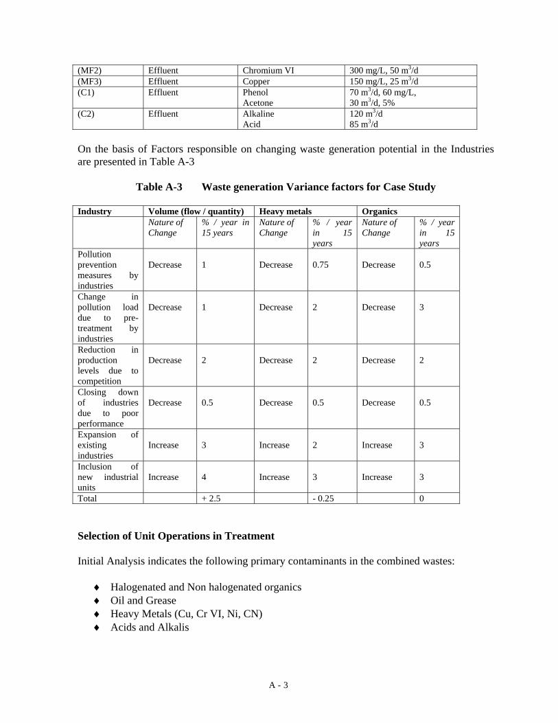
A - 3
(MF2) Effluent Chromium VI 300 mg/L, 50 m3/d (MF3) Effluent Copper 150 mg/L, 25 m3/d (C1) Effluent Phenol
Acetone 70 m3/d, 60 mg/L, 30 m3/d, 5%
(C2) Effluent Alkaline Acid
120 m3/d 85 m3/d
On the basis of Factors responsible on changing waste generation potential in the Industries are presented in Table A-3
Table A-3 Waste generation Variance factors for Case Study Industry Volume (flow / quantity) Heavy metals Organics Nature of
Change % / year in 15 years
Nature of Change
% / year in 15 years
Nature of Change
% / year in 15 years
Pollution prevention measures by industries
Decrease
1
Decrease
0.75
Decrease
0.5
Change in pollution load due to pre-treatment by industries
Decrease
1
Decrease
2
Decrease
3
Reduction in production levels due to competition
Decrease
2
Decrease
2
Decrease
2
Closing down of industries due to poor performance
Decrease
0.5
Decrease
0.5
Decrease
0.5
Expansion of existing industries
Increase
3
Increase
2
Increase
3
Inclusion of new industrial units
Increase
4
Increase
3
Increase
3
Total + 2.5 - 0.25 0 Selection of Unit Operations in Treatment Initial Analysis indicates the following primary contaminants in the combined wastes:
♦ Halogenated and Non halogenated organics ♦ Oil and Grease ♦ Heavy Metals (Cu, Cr VI, Ni, CN) ♦ Acids and Alkalis

A - 4
Waste Segregation
• For BD1 and BD2 Halogenated and non halogenated solvent streams should be separate if possible.
• For MF1, Ni and CN streams should be segregated • For MF1, MF2 and MF3 segregate degreasing and metal streams • Mix acidic and alkaline streams in precipitation tank to adjust pH to reduce the need
for extra acid or alkali requirement The box below categorises the wastes in terms of quantities under similar waste types. Liquid Waste / Slurry sold waste streams The summary of results as obtained from Excel spreadsheet are presented in Table A-4 below. The last column indicates the final volumes as corrected from the WGVF.
Table A-4 Summary of Waste Streams
Waste Stream Category Total Total with WGVF Stream 1 No pretreatment reqd.
(neutral wastes, low metal and SS)
Volume (m3/d) 0 0Stream 2 Acidic WW with Heavy metals
Volume (m3/d) 325 333 Oil and Grease (mg/L 0 Concentration (mg/L) 450 337.5 Solvent (% by weight)
Stream 3 Acidic WW without Heavy metals Oil and Grease (mg/L 0 Volume (m3/d) 235 240 Solvent (% by weight) 0
Stream 4 Acidic wastes with Phenol Volume (m3/d) 70 72 Concentration (% by weight) 60 60
Stream 5 Acidic wastes with chrome VI Volume (m3/d) 150 154 Concentration (mg/L) 500 375
Stream 6 Acidic wastes with emulsified petroleum hydrocarbons
Volume (m3/d) 0 0 Concentration (mg/L) 0 0
Stream 7 Wastes with organics / oily wastes, solvents
Volume (m3/d) 1355 1389 SS (mg/L) 0 Oil and Grease (mg/L) 455 340

A - 5
Concentration (% by weight) 35 35Stream 8 Alkaline wastes with cyanide
Volume (m3/d) 160 164 Concentration (mg/L) 60 45 Oil and Grease (mg/L) 0 Slurry / Sludge waste
Stream 9 Sludges with heavy metals (tons/d) 0 0
Total Metal Concentration (ppm) 0 % Moisture (total)
Stream 10 Sludges with toxic organics (% by Weight)
25 25
Tons/d 0.6 0.6
% Moisture (total) 63.00 63.00 Unit Operations necessary The fundamental unit operations necessary are selected from the Excel spreadsheet as below, The decision for solvent recovery technology (stripping or SCF) and thermal technology (Rotary Kiln or Fluidised Bed) was taken on the basis of the AHP model. The elimination of stripping technology was based on the Sample Calculations sheet in Excel. - Physico chemical treatment
Neutralisation (N) Chromium reduction Cyanide Oxidation Metal Chemical Precipitation (P) - Oil and Grease Removal (Floatation, FL) - Solvent Recovery and extraction (SCF) - Incineration (Rotary Kiln, T) - Secure Landfilling Note: Ion exchange technology has been eliminated because these would require high amount of heavy metals for recovery potential. Membrane technology also has been eliminated since salt removal is not required. The requirement of Incineration is based on the quantity of the incinerable waste and their incinerability which is calculated as below: I = C + (a/H) Where, C = concentration of contaminant (%)

A - 6
a = dimensionless constant = 100 Kcal /gram H = Heating value of the waste contaminant Kcal / gram The POHCs identified was Chlorobenzene, for which trial burn is recommended (Sample Calculations sheet from Excel). In this casestudy, incineration is a probable candidate because the incinerable content in the wastes (mainly liquid / slurry) are high. Due to the fact that the sludge generated is not high, either fluidised bed or rotary kiln will have to be selected. The solvent recovery technology will separate our solvents in vapour form and these can be fed to the incinerator for combustion. The incinerable wastes from the profile could be:
♦ Oil and grease ♦ Solvents (gaseous) ♦ Organic sludge
The technology selection and routing screen is presented in Table A-5,
Table A-5 Recommendation on Technologies for various streams
Recommendation on Technologies for various Streams Technology 1 Technology 2 Technology 3 Technology 4
Stream Number
Stream 1 P L Stream 2 N P D L Stream 3 N P Stream 4 SCF T Stream 5 Chrome
Reduction P S L
Stream 6 FL T Stream 7 SCF T Stream 8 Cyanide
Oxidation P S L
Stream 9 Stream 10 D T
The sludges from the physico chemical treatment of metal bearing streams should be landfilled. The landfill also needs to incorporate the drums and packed mixed hazardous waste which cannot be segregated and treated. These wastes should be stabilised and then landfilled. The stabilisation could either be chemical or simple physical encapsulation. Thermal (Rotary Kiln) should be followed by Wet Scrubber for air emission control.

Planning a Central Hazardous Waste Treatment and Disposal Facility
Analysis of Technology AlternativesAnalysis of Technology Alternatives
Rahul Datar
IndustriesCHWTDF

Objectives
To develop a Conceptual Framework for Treatment TechnologySelection in the Design and Operation of CHWTDFs
To develop a basic Excel spreadsheet to appraise a mixed waste composition and select technology
To develop a Basic Pricing Model for charging member Industries
Scope of Study• Inventorisation and Characterization of wastes is ignored • Study conducted only for selected industries• Focus is Knowledge Base, not Optimisation• Risk not considered• Hypothetical data• Pricing based on PPP

Individual Waste Treatment for Industries
Central Waste Treatment Facilities
- Expensive- Skilled Operation- Responsibility to comply with standards+ Self Management+ Suitable for conventional waste treatment
(low maintenance and expertise required)- Moderate to High Risk
+ Economies of Scale+ Better for Regulatory Authority to monitor + Better and planned Management (long term option)+ Reduction in Infrastructural requirements- High Risk of Failure (waste supply, institutional, etc.)+ Better environmental protection

Components of a Central Hazardous Waste Treatment and Disposal Facility
InfrastructureWaste storage tanks and area (based on waste waste compatibility)Piping and Pumping equipment as per requirementLaboratory FacilitiesTechnology InstallationsElectrical SupplyOffice and Administrative Buildings
Design BasisExpected Waste type, quantity and Quality (future estimates)Minimize Cost of TreatabilityWaste Waste CompatibilityOptimised Routing of WastesSecondary waste generation control equipment (air emissions etc.)

Hazardous Waste ClassificationSize of IndustryForm
- Liquid / Aqueous- Solid / Sludge
Hazard Characteristic- Ignitability- Corrosivity- Reactivity- Toxicity
Category- Inorganic
- Heavy Metal- Organic
- Solvents
Cla
ssifi
catio
n ba
sed
on

Waste Generation Variance Factors (WGVF)Waste Generation Variance Factors (WGVF)
Waste Minimization in IndustriesPretreatment in IndustriesExpansion of IndustriesClose down of IndustryDecrease in Production of industry due to market failures
Waste Minimization
• Process Modification• Equipment Modification• Reuse / Recycle / Recovery• Material Substitution• Housekeeping
Criteria for estimating WM
• Type of Industry• Size of Industry• Management Policy• Affordability• Time (innovations in
technologies)

Waste SegregationNeed♦ To reduce hazard in storage and treatment♦ To ease treatment of specific contaminants (avoid interferences)♦ To ease charging of member industries♦ To ease material recovery
Types of segregation† Industry level (entry condition to CHWTDF)† Segregation at the CHWTDF before treatment
ExamplesNickel and Cyanide streamsCadmium and Cyanide streamsHexavalent Chrome from other heavy metalsMercury bearing streams should be separateHalogenated and Non halogenated streams

Waste Waste CompatibilityAllowed
Oxidising mineral acids and toxic metal compounds (metal industry)Alkaline / caustic and Cyanide (metal finishing)Halogenated and non halogenated storage togetherPhenols and Organic acids (agrochemical / chemical )Acids and Alkalis should be mixed but not stored together
Not Recommended
Halogenated Organics and Mineral Acid streams (chemical industry)Cyanides and Mineral Acid streams (metal)Organic acids (acetic, formic - Chemical industry) and metals / acidsPesticides and Acidic / Alkaline streams (Agrochemical / Chemical)

Selection of TechnologyIn Basic DesignIn Basic DesignDuring Operation of the CHWTDFDuring Operation of the CHWTDF
Criteria used in Basic DesignEssential Unit Operations (S, F, D etc.)Dedicated Specific Technologies (I, T, M etc.)Multi-applicability of technologies to all accepted wastesWaste generation estimation over entire life span (WGVF)
Criteria used during operation of CHWTDCategorisation of waste into streams according to treatmentBest technology based on need, performance and costMinimisation of waste residuesCompliance with standards before discharge / disposal
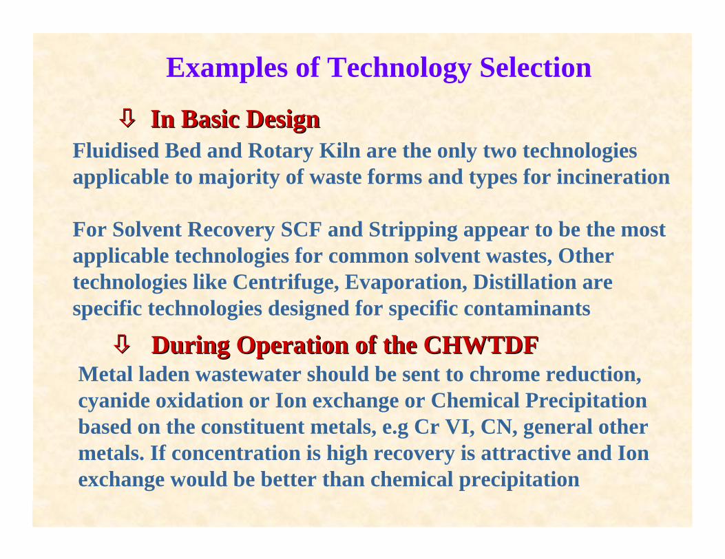
Examples of Technology Selection
In Basic DesignIn Basic DesignFluidised Bed and Rotary Kiln are the only two technologiesapplicable to majority of waste forms and types for incineration
For Solvent Recovery SCF and Stripping appear to be the most applicable technologies for common solvent wastes, Other technologies like Centrifuge, Evaporation, Distillation are specific technologies designed for specific contaminants
During Operation of the CHWTDFDuring Operation of the CHWTDFMetal laden wastewater should be sent to chrome reduction, cyanide oxidation or Ion exchange or Chemical Precipitationbased on the constituent metals, e.g Cr VI, CN, general other metals. If concentration is high recovery is attractive and Ion exchange would be better than chemical precipitation

Technologies for hazardous Waste Treatment
PhysicoPhysico ChemicalChemical
SedimentationFloatationNeutralisationFiltrationSuper Critical FluidsDewateringCarbon AdsorptionReverse OsmosisUltrafiiltrationElectrodialysisChemical PrecipitationIon Exchange
ThermalThermal
Liquid InjectionRotary KilnFluidised BedIndustrial BoilersWet Air OxidationPyrolysis
DisposalDisposal
Chemical StabilisationSecure Landfill

Example of a Closed Loop for a Waste Stream
Consider a Waste stream with low solids, high volatile organics,high non volatile organics and high amount of heavy metals
SS /SCF P C / Muf Discharge
T T
D ST L
Leachate
Waste Waste FeedFeed
Ash
Air emission control
Air emission control
Decision Point

Sequencing of TechnologiesFloatation should be prior to SCF or Solvent StrippingFloatation should be prior to SCF or Solvent StrippingNeutralisation should be used prior to Precipitation for highly Neutralisation should be used prior to Precipitation for highly
acidic metal bearing waste streamsacidic metal bearing waste streamsSedimentation should always follow Precipitation / OxidationSedimentation should always follow Precipitation / OxidationFiltration / Carbon adsorption should be used in conjunctionFiltration / Carbon adsorption should be used in conjunction
as per the solids in the supernatant to be polishedas per the solids in the supernatant to be polishedSolvent Recovery should always be before Metal removalSolvent Recovery should always be before Metal removalCarbon Adsorption should always be after Floatation and / or Carbon Adsorption should always be after Floatation and / or
Sedimentation Sedimentation Metal removal should precede Metal removal should precede UltrafiltrationUltrafiltrationReverse Osmosis should always be after Metal removal and SS Reverse Osmosis should always be after Metal removal and SS
removalremovalStabilisationStabilisation should precede should precede LandfillingLandfilling if reactive unstable if reactive unstable
metals like Hg are presentmetals like Hg are present

Management Aspects of CHWTDF
Waste Inventory Buildup - realistic estimates with safety factors
Storage Scheduling (minimum waiting time, minimum risk)
Technology Selection Planning (waste streams, batch / continuous)
Optimal Waste Routing Planning (say over a month of operation)
Efficient Waste Monitoring during operation
Technology Equipment Maintenance
Risk Aversion
Waste Inventory Buildup Waste Inventory Buildup -- realistic estimates with safety realistic estimates with safety factorsfactors
Storage Scheduling (minimum waiting time, minimum risk)Storage Scheduling (minimum waiting time, minimum risk)
Technology Selection Planning (waste streams, batch / Technology Selection Planning (waste streams, batch / continuous) continuous)
Optimal Waste Routing Planning (say over a month of Optimal Waste Routing Planning (say over a month of operation)operation)
Efficient Waste Monitoring during operationEfficient Waste Monitoring during operation
Technology Equipment MaintenanceTechnology Equipment Maintenance
Risk AversionRisk Aversion

Analytical Hierarchy Process
Tool for multi criteria decision makingCan be used efficiently for Technology Selection in a CHWTDF
StructureThe AHP is modeled in the software ExpertChoice Ver. 9.0It accepts decision alternatives It accepts criteria which affect the decisionIt constructs matrices of preferences of alternatives over differentcriteria and amongst the criteria themselvesNormalises the matrix product and present a total score for each alternativeThe Highest Score indicates the Best Alternative
Significant FeatureOnline Sensitivity Analysis to emulate changes in Online Sensitivity Analysis to emulate changes in alternatives ranking upon change in criteria and weightagesalternatives ranking upon change in criteria and weightages

A Typical AHP Synthesis Screen for Thermal Technologies

Pricing Model for Member Industries in CHWTDF
Factors affecting
• Ownership Models• Affordability and Willingness to pay• Capital Cost Fraction• Treatment Cost• Transportation Cost• Risk Cost
For CHWTDFFor CHWTDFFee is a function of the miscellaneous fixed cost fractions andFee is a function of the miscellaneous fixed cost fractions andthe the treatabilitytreatability cost based on the route taken by the Waste Streamcost based on the route taken by the Waste Stream
Fee = Σ for routes used (Technology cost * quantity of waste) + Fraction cost for unused technologies + labour cost - rebate if recovery used + Risk factor cost (0.5% of earlier sum) + Capital Cost fraction

Conclusions and Recommendations
• The proposed framework presents a rationale for the technologyselection in the design and operation of a CHWTDF
• It proposes the use of Analytical Hierarchy Process for technology selection
• It demonstrates the use of an Excel spreadsheet to appraise amixed waste matrix and evaluate technology options
• Further studies exploring selection rules and interferences from other contaminants from commercial suppliers
• Expansion of Excel worksheet to include pricing structure
• Development of optimisation model to select best technologyon the basis of performance and cost
Conc
lusi
ons
Reco
mm
enda
tion
s