Pixhawk Pilot Support Package User Guide - … Product Description The Pixhawk Pilot Support Package...
71
Pixhawk Pilot Support Package (PSP) User Guide Version 2.1 ISSUE DATE: February 2017 MathWorks Pilot Engineering Group
Transcript of Pixhawk Pilot Support Package User Guide - … Product Description The Pixhawk Pilot Support Package...

Pixhawk Pilot Support Package (PSP) User Guide
Version 2.1
ISSUE DATE: February 2017
MathWorks
Pilot Engineering Group

1 Product Description .................................................................................................... 4
1.1 Basic Software Environment Description ............................................................ 4 1.2 Acronyms/Definitions .......................................................................................... 5 1.3 Contact Information ............................................................................................. 5
2 Document History ....................................................................................................... 5 3 System Requirements.................................................................................................. 5
3.1 MATLAB/Simulink Toolboxes ........................................................................... 5 3.2 Required (Windows) ............................................................................................ 6 3.3 Required (Linux) .................................................................................................. 6
4 Installation................................................................................................................... 6 4.1 Pixhawk Toolchain Install (Windows) ................................................................. 7 4.2 Pixhawk Toolchain Install (Linux) ...................................................................... 7 4.3 Pixhawk Toolchain MathWorks PSP Install (Linux/Windows) .......................... 9
4.4 Toolchain Firmware Download and Compilation (Windows) ........................... 10 4.5 Firmware Download and Compilation (Linux) .................................................. 11
5 Getting Started .......................................................................................................... 12 5.1 Pixhawk Environment ........................................................................................ 12
5.2 Firmware Startup Preparation ............................................................................ 16 5.3 Simulink Code Generation and Compilation ..................................................... 17
Simulink Settings ........................................................................................ 17
Target Hardware Resource Options ............................................................ 19 Building the Firmware ................................................................................ 21
5.3.3.1 Build, Download and Run ....................................................................... 21 5.3.3.2 Build Only ............................................................................................... 23
Firmware and Code Generation structure ................................................... 24
Hard Real-Time Constraints ....................................................................... 25
5.4 Using QGroundControl with Pixhawk PSP for sensor calibration .................... 27 5.5 Simulink Block Library ...................................................................................... 29
Pixhawk Target Block: input_rc ................................................................. 30
Pixhawk Target Block: PWM_output ......................................................... 31 Pixhawk Target Block: Speaker_Tune ....................................................... 32
Pixhawk Target Block: RGB_LED ............................................................ 34 Pixhawk Target Block: sensor_combined .................................................. 35
Pixhawk Target Block: vehicle_attitude ..................................................... 37 Pixhawk Target Block: vehicle_gps ........................................................... 38 Pixhawk Target Block: Battery_measure ................................................... 40 Pixhawk Target Block: Binary Logger ....................................................... 41
Pixhawk Target Block: Example Print Function ........................................ 41
Pixhawk Target Block: Read ADC Channels ............................................. 42
Pixhawk Target Block: uORB Write .......................................................... 43
Pixhawk Target Block: uORB Read / Function-Call Trigger ..................... 44 5.6 Example Models ................................................................................................. 47
px4demo_Parameter_CSC_example.slx ..................................................... 47 px4demo_ADC_example.slx ...................................................................... 48 px4demo_input_rc.slx ................................................................................. 49 px4demo_rgbled.slx .................................................................................... 49

px4demo_tune.slx ....................................................................................... 49
px4demo_gps.slx ........................................................................................ 50 px4demo_attitude_plant.slx ........................................................................ 51 px4demo_attitude_control.slx ..................................................................... 52
px4demo_attitude_system.slx ..................................................................... 53 px4demo_fcn_call_uorb_example.slx ........................................................ 53 px4demo_write_uorb_example.slx ............................................................. 54 Serial Communication ................................................................................ 55
6 Building your own custom Simulink Block.............................................................. 56
S-Function Approach .................................................................................. 56 MATLAB Function blocks and System Objects ........................................ 57
7 Limitations ................................................................................................................ 58 Support for HIL / Mavlink .......................................................................... 58
Supporting C++ uORB Message Data Structures ....................................... 58 8 Updating to a new version of Pixhawk PSP ............................................................. 60
9 Using External Mode with the Pixhawk PSP ........................................................... 61 9.1 What is External Mode? ..................................................................................... 61
9.2 Some important considerations: ......................................................................... 62 10 External Mode Tutorial Part 1: ................................................................................. 62
10.1 Viewing Signals from the generated Code ..................................................... 62
Serial port setup: ....................................................................................................... 62 10.2 Model Configuration Setup: ........................................................................... 64
10.3 Running the example model ........................................................................... 65 11 External Mode Tutorial Part 2: External Mode Control Panel ................................. 66
11.3 Tips for logging fast-rate signals .................................................................... 68
11.4 Background Task vs Normal EXT Mode Behavior ....................................... 69
12 External Mode Tutorial Part 3: Tuning parameters .................................................. 69

1 Product Description
The Pixhawk Pilot Support Package (PSP) feature allows users to use Simulink models to
generate code targeted for the Pixhawk FMUv2 (Flight Management Unit). The PSP
provides the ability to incorporate the Pixhawk Toolchain for complete firmware build and
download to the px4fmu Version 2 unit. It does not provide exact function behavior blocks
for other services running on the Pixhawk (e.g. Attitude Estimation using EFK or SOF).
The user will need to use blocks from the base Simulink or possibly the Aerospace blockset
for simulating their flight control system model. Once the flight control system (FCS) has
been successfully modeled, simulated and verified, the Pixhawk Target can be used to
deploy the control system onto the PX4 hardware.
The Pixhawk Simulink blocks allows users to access sensor data and other calculations
available to be used in their Simulink model at runtime. Generated code can then be
compiled and executed on the Pixhawk platform controlling a multi-rotor airframe.
1.1 Basic Software Environment Description
The Pixhawk Pilot Support Package is based off of a forked version of the official
Pixhawk Firmware. This forked version can be found here.
https://github.com/darenlee/PixhawkPSP_Firmware/tree/PSP_R2016AB
During the PSP installation process, a download script will automatically clone this
repository. This forked version is roughly based off of the 1.3.4 tag
https://github.com/PX4/Firmware/releases/tag/v1.3.4
A NuttX application called “px4_simulink_app” is created using this PSP and code
generation tools. This application follows the same code structure and format
depicted here.
http://dev.px4.io/tutorial-hello-sky.html
This Pilot Support Package has been tested with the Pixhawk FMUv2 which can be
configured to run different CMake configurations through the installation process. We
have tested the “default” configuration and “ekf2” but we also allow you to specify
your own custom CMake configuration.
Since this package is generating code for a Simulink PX4 module, our PSP adapts the
Simulink code generation and compilation process to fit into the Pixhawk build
environment by making use of CMake. A CMake command is executed compile the
Pixhawk Firmware to invoke compilation.
Ideally, one should be familiar with the embedded software environment of the PX4
platform prior to using this Pilot Support Package. For more information on this, refer
to the later sections that go into details about the code generation process as well as the
PSP installation section.

1.2 Acronyms/Definitions
Pixhawk (PX4) – the Flight Controller Unit providing various sensor value inputs and
PWM outputs as well as an ARM Cortex-M4 microprocessor for flight control and
management.
PSP – Pilot Support Package. MathWorks software offering customized feature
development or updates that are not yet available in the officially released version of
MATLAB/Simulink.
TLC – Target Language Compiler
BTI – Built Tool Integration
FMU – Flight Management Unit
PWM – Pulse Width Modulation
RC – Radio Control
Tx/Rx – Transmitter/Receiver
ESC – Electronic Speed Controller
NED – North-East-Down
1.3 Contact Information
Steve Kuznicki – MathWorks. [email protected]
Daren Lee – MathWorks [email protected]
2 Document History Date Version Author Description
1 Oct 2014 1.0 SEK Initial version.
22 April 2015 1.2 DL updates
Nov 2015 1.3 DL updates
Nov 2015 1.3.1 DL update CSC fix
Aug 2016 1.3.4 DL Beta updates
Dec 2016 2.0 SEK Updates to support package blocks, etc…
Feb 2017 2.1 DL Bug fixes, R2016b release
3 System Requirements
3.1 MATLAB/Simulink Toolboxes
To generate code from a Simulink model, the following products are needed:
MATLAB R2016a / R2016b
Simulink
Simulink Coder
Embedded Coder
Aerospace Blockset is needed for some of the example models

3.2 Required (Windows)
PX4 Toolchain Installer v1.4 for Windows
To successfully work with the PX4 and deploy the generated firmware to the
Pixhawk this additional software is needed
Pixhawk Toolchain
CMake (tested with CMake 3.6.0)
QGroundControl (Optional : Tested on 2.7.1 and 2.8.0)
NOTE (Windows): The Pixhawk Toolchain must be fully installed prior to running
the Pixhawk PSP. Please ensure that no Firmware directory exists already.
3.3 Required (Linux)
Git
arm-none-eabi-gcc (GNU Tools for ARM Embedded Processors) 4.8.4
Python 2.7.6 / 2.7.12 (tested on both)
o Additional Python Package: sudo apt-get install python python-tk CMake (tested with 3.5.1)
Other software (see installation details Section 4.2)
NOTE (Linux): Compilation of the firmware can actually fail on newer versions of
the arm-none-eabi-gcc. All tests with the Pixhawk PSP were conducted on version
arm-gcc 4.8.4. Similarly, the Simulink code generation process can fail too without
obtaining the latest version of Python.
For more detail on how to use QGroundControl with the PixhawkPSP please refer to
5.4 Using QGroundControl with Pixhawk PSP ............. Error! Bookmark not defined.
4 Installation This PSP is supported on Win64 and Linux platforms.
Platform Installation Program
Windows-7 64 Pixhawk-<MATLAB_VERSION>_v1.x_win64-Install.exe
Linux 64 Pixhawk-<MATLAB_VERSION>_v1.x_glnxa64-Install
It is IMPORTANT for you to install the PX4 Toolchain software on your machine FIRST.
The Pixhawk PSP installer needs to know the Root directory of the Pixhawk Toolchain
since it modifies some of its files. The PSP installer is responsible for modifying the tool
chain files to fetch files from a forked PX4 repository containing firmware source files.
This forked repository contains modifications that are needed to interface with the PSP.

4.1 Pixhawk Toolchain Install (Windows)
You should download and install the Pixhawk Toolchain from http://www.pixhawk.org/
under the Downloads section.
This PSP was tested with version 1.4 found here:
http://www.inf.ethz.ch/personal/lomeier/downloads/px4_toolchain_installer_v14_win.exe
For the Pixhawk Toolchain installation:
Launch the installation program for your operating system.
Read and accept the licensing agreement
Specify the location for the Toolchain installation. It is recommended that you
choose the default of “c:\px4”
You may also need to install a USB driver if you are using Windows. See the Pixhawk
Downloads page for more information HERE.
Before proceeding to the next steps for firmware building please also download CMake.
https://CMake.org/download/
Version 3.6.0 is recommended as this was used to test with the PSP. You will also need
to add CMake to your Windows path as shown below:
After downloading and installing the Pixhawk Toolchain you will want to install the
Pixhawk PSP described below.
4.2 Pixhawk Toolchain Install (Linux)
As opposed to the Windows version of the installation, the embedded GCC compiler is
assumed to be already installed. There is no pre-packaged “toolchain” to download like the
Windows version. Assuming that the correct Linux packages are installed (see software
requirements above) the only step that is needed here is to clone the Git repository
containing the correct firmware version and then build it. The installer will ask you to select
a directory to specify where this firmware will be placed.

Special Notes:
As mentioned in the beginning of this document, it is highly suggested to use the
GCC-ARM version 4.8 compiler. The commands to do this are listed below.
In Ubuntu, you may will need write access sudo permissions for your MATLAB
installer. This means the ability to write files/folders in the MATLAB directory.
You may need to enable write permissions or else the installation can fail. To see
an example of how one can enable write permissions please see the notes here:
http://superuser.com/questions/19318/how-can-i-give-write-access-of-a-folder-to-
all-users-in-linux
Enable this option on the location of where you wish to install the PSP folder (ie:
usr/local/MATLAB/<MATLAB_RELASE>/toolbox/psp)
You might need to also install a python package for pop-up window UI support.
This can be obtained via: sudo apt-get install python python-tk
Below are a set of commands that fetches all the correct packages to support version GCC-
ARM 4.8 as well as other utilities (Cmake, Python, etc). This has been tested on Ubuntu.
You may need to modify these commands depending on what existing packages you may
or may not have. These instructions come from these pages here:
http://dev.px4.io/starting-installing-linux.html
http://dev.px4.io/starting-installing-linux-boutique.html
#recommended from install guide sudo usermod -a -G dialout $USER
#install CMakeand other px4 tools sudo add-apt-repository ppa:george-edison55/CMake-3.x -y sudo apt-get update sudo apt-get install python-argparse git-core wget zip \ python-empy qtcreator CMake build-essential genromfs -y # simulation tools sudo apt-get install ant protobuf-compiler libeigen3-dev libopencv-dev openjdk-8-jdk openjdk-8-jre clang-3.5 lldb-3.5 -y
#recommended from install guide sudo apt-get remove modemmanager sudo apt-get update #Get python
sudo apt-get install python-serial openocd \ flex bison libncurses5-dev autoconf texinfo build-essential \ libftdi-dev libtool zlib1g-dev #Get GCC ARM Compiler version 4.8 pushd . cd ~ wget https://launchpadlibrarian.net/186124160/gcc-arm-none-eabi-4_8-2014q3-20140805-linux.tar.bz2 tar -jxf gcc-arm-none-eabi-4_8-2014q3-20140805-linux.tar.bz2

exportline="export PATH=$HOME/gcc-arm-none-eabi-4_8-2014q3/bin:\$PATH" if grep -Fxq "$exportline" ~/.profile; then echo nothing to do ; else echo $exportline >> ~/.profile; fi . ~/.profile Popd #Get 32-bit libraries sudo apt-get install libc6:i386 libgcc1:i386 gcc-4.8-base:i386 libstdc++5:i386 libstdc++6:i386
4.3 Pixhawk Toolchain MathWorks PSP Install (Linux/Windows)
For the Pixhawk PSP installation:
1) Launch the installation program (e.g. pixhawk-R2015b-v1.3.1_win64-
Install.exe)
2) Read and accept the licensing agreement
3) Specify the MATLAB Root directory of your R2016b/R2016a installation.
For example c:\MATLAB\R2016a (Windows) or
/usr/local/MATLAB/R2016a/ (Linux)
4) Specify the Pixhawk Toolchain Root directory (e.g. c:\px4). On Windows this
is where your PX4 Toolchain is installed. On Linux this directory is a folder
location that you specify where the PX4 firmware will be placed.
5) The Installer will verify the MATLAB Version and the Pixhawk Toolchain
directory.
6) It will launch MATLAB in the background and run a script to finish the
installation (this will take some time, please wait for the Next> button to show
in the installer dialog).
7) You will then be prompted to select a particular Firmware configuration.
As mentioned in an earlier section, this screen allows you to select which
CMake configuration you want to use in the build process. Default and EKF2

are the ones that come with the Pixhawk Firmware but a user can also specify
their own custom configuration by using the “Specify configuration” tick-box.
You are also free to edit and customize these configurations as needed which
you can find within ‘<px4_directory>\Firmware\CMake\configs’.
NOTES: The next steps after this install process will require you to compile the
firmware. If you compiled a firmware configuration and want to switch to a
different configuration, you may need to perform a ‘make clean’ on the build
output directory or delete it. The Build output directory is listed in the above
user interface diagram. In this example it is located in
‘c:\px4\Firmware\build_px4fmu-v2_default’. This is the output of compilation
of the firmware.
8) If the installation script fails, a MATLAB command window will show any
errors that may have occurred. If this happened, please copy and paste this
window content and email it back to the Pilot Team for help.
9) After installation on a Windows-7 machine, you may get a pop-up dialog asking
if the software installed correctly. Simply answer ‘Yes’ to this dialog. This is
just an artifact of using an installer that works on a Win32 machine as well.
The PSP will install itself in the <matlabroot>\toolbox\psp\pixhawk directory. The
Simulink Pixhawk Blockset and MATLAB Pixhawk Toolchain BTI functions are now
installed and ready to use. You should copy the example models out of the
<matlabroot>\toolbox\psp\pixhawk\examples directory to your own working directory.
4.4 Toolchain Firmware Download and Compilation (Windows)
One last step before being able to use the PSP is to perform a Pixhawk software update
and pre-compiling source firmware source files. This is done by choosing the “PX4
Software Download” option in the PX4 Toolchain application Windows folder menu:

This download script has been modified in the PSP installer to download from a Github
repository containing a forked stable copy of the PX4 FMU firmware. This stable-release
will be revisited from time to time by MathWorks Pilot Engineering to ensure appropriate
updates are applied from the official firmware when necessary (ie: bug fixes, feature
updates). Please contact us regarding any discrepancies between the forked and the official
repo. In this version of the PSP, we are using work based off of the ‘1.3.4 tag’ release.
IMPORTANT: Please ensure that the instructions followed so far are with a fresh install
of the PX4 tool chain. Sometimes git-related errors can occur if the Firmware directory is
already populated with files and will fail to clone files from the repository.
After you do an initial software download you need to build the necessary target files.
This can take up to half-hour or longer. This should only need to be done once.
1) Choose the “PX4 Console” option from the Windows PX4 Toolchain start menu.
2) Once the MINGW32 window appears, change directory to Firmware. e.g. cd
Firmware
3) Build all the modules: make <CMake_CONFIG>
Where <CMake_CONFIG> will depend on which configuration you selected
during the PSP installation. For instance, if you plan to use the ekf2, you would
use make px4fmu-v2_ekf2
Or the default configuration make px4fmu-v2_default
This process can take up to 20-30 minutes. Wait until the Firmware has been built. On
some Windows machines, it has been observed that there is a chance that this build can fail
due to parallel build issues. You may see error messages along the lines of “unable to
rename file” or some permission settings. If it gets stuck in this state, exit out by using
CTRL+C and run the same make command as in step 3). The build procedure will resume
where it left off so it will not perform a “make clean” and start from scratch.
NOTE: Disabling virus scanner has been observed to also dramatically decreased the
chances of this happening. Please temporarily disable virus scanning utilities during this
process
4.5 Firmware Download and Compilation (Linux)
After downloading the correct packages and installing the Pixhawk PSP, the next steps
are:

1) Depending on which folder you selected for specifying the Px4 directory in the
installation process you will want to navigate to that directory and run the shell script
inside. This script will grab a forked version of the PX4 firmware.
<selected directory during PSP install>/px4/toolchain/msys/1.0/px4_download_software.sh
Where <selected directory>/ is the directory you specified in step 4) for section 4.3
This should begin to clone a repository <selected directory>/Firmware
It is important to note that the /Firmware folder should NOT exist prior to running this
shell script or the Git clone can fail to retrieve all the files.
2) Once downloading has been completed
Build all the modules: make <CMake_CONFIG>
Where <CMake_CONFIG> will depend on which configuration you selected during the
PSP installation. For instance, if you plan to use the ekf2, you would use make px4fmu-v2_ekf2
Or the default configuration make px4fmu-v2_default
5 Getting Started
5.1 Pixhawk Environment
Using the default firmware available for the Pixhawk, you should test to make sure
your hardware is correctly configured and works as intended. This includes the
correct motor wiring, placement of the PX4 module and any other sensors you may
be using. You can use QGroundControl to download and flash the necessary
firmware for this test.
You can launch a serial terminal program like TerraTerm or PuTTY and connect to
the PX4 and manually run the built-in commands using the nuttx shell. NuttX is the
OS that is delivered with the Pixhawk toolchain and will be used for running the code
generated from your Simulink models.
You can find out which “Builtin” Apps your firmware has by typing “?” at the nuttx
shell prompt “nsh>”
nsh> ?
help usage: help [-v] [<cmd>]
df kill mkrd rm unset ? echo losetup mh rmdir usleep
cat exec ls mount set xd cd exit mb mv sh cp free
mkdir mw sleep cmp help mkfatfs ps test dd hexdump

mkfifo pwd umount
Builtin Apps:
sercon
serdis
adc
attitude_estimator_ekf
bl_update
blinkm
boardinfo
commander
…
Some useful commands are: 1) esc_calib – to calibrate your ESCs through the command
line interface
usage:
[-d <device>] PWM output device (defaults to
/dev/pwm_output)
[-l <pwm>] Low PWM value in us (default: 1000us)
[-h <pwm>] High PWM value in us (default: 2000us)
[-c <channels>] Supply channels (e.g. 1234)
[-m <chanmask>] Directly supply channel mask (e.g. 0xF)
[-a] Use all outputs
2) pwm – to test out your PWM outputs usage:
pwm
arm|disarm|rate|failsafe|disarmed|min|max|test|info ...
arm Arm output
disarm Disarm output
rate ... Configure PWM rates
[-g <channel group>] Channel group that should
update at the alternate rate
[-m <chanmask> ] Directly supply channel mask
[-a] Configure all outputs
-r <alt_rate> PWM rate (50 to 400 Hz)
failsafe ... Configure failsafe PWM values
disarmed ... Configure disarmed PWM values
min ... Configure minimum PWM values
max ... Configure maximum PWM values
[-c <channels>] Supply channels (e.g. 1234)
[-m <chanmask> ] Directly supply channel mask
(e.g. 0xF)

[-a] Configure all outputs
-p <pwm value> PWM value
test ... Directly set PWM values
[-c <channels>] Supply channels (e.g. 1234)
[-m <chanmask> ] Directly supply channel mask
(e.g. 0xF)
[-a] Configure all outputs
-p <pwm value> PWM value
info Print information about the PWM device
-v Print verbose information
-d <device> PWM output device (defaults
to /dev/pwm_output)
3) tests – run various built-in test on the pixhawk hardware
nsh> tests help
Available tests:
led
int
float
sensors
gpio
hrt
ppm
servo
ppm_loopback
adc
jig_voltages
uart_loopback
uart_baudchange
uart_send
uart_console
hott_telemetry
tone
sleep
time
perf
all
jig
param
bson
file
file2
mixer

rc
conv
mount
mtd
mathlib
help
4) top – will list all the NuttX processes running at the time (press ‘q’ to quit)
Processes: 11 total, 2 running, 9 sleeping
CPU usage: 37.36% tasks, 0.48% sched, 62.16% idle
Uptime: 904.233s total, 561.039s idle
PID COMMAND CPU(ms) CPU(%)
USED/STACK PRIO(BASE) STATE
0 Idle Task 561039 62.162 0/
0 0 ( 0) READY
1 hpwork 26060 2.799 748/
1992 192 (192) w:sig
2 lpwork 6784 0.675 628/
1992 50 ( 50) READY
85 top 116 1.158 1244/
1696 100 (100) RUN
7 nshterm 121 0.000 884/
1192 100 (100) w:sem
9 px4io 9444 0.965 796/
1992 240 (240) w:sem
26 sensors_task 38995 4.440 1364/
1992 250 (250) w:sem
38 px4SimTermTask 1 0.000 524/
2040 100 (100) w:sem
29 attitude_estimator_ekf 191254 20.945
13004/13992 250 (250) w:sem
40 px4SimBaseTask 49428 5.501 1164/
2552 100 (100) w:sem
42 px4SimSchedTask 7819 0.868 1028/
2040 100 (100) READY
5) SD card logging – useful for logging data to the SD Card
sdlog2: usage: sdlog2 {start|stop|status} [-r <log
rate>] [-b <buffer size>] -e -a -t -x
-r Log rate in Hz, 0 means unlimited rate
-b Log buffer size in KiB, default is 8
-e Enable logging by default (if not, can
be started by command)

-a Log only when armed (can be still
overriden by command)
-t Use date/time for naming log
directories and files
-x Extended logging
5.2 Firmware Startup Preparation
Executing the default firmware, there are several processes that get executed at
system startup. When deploying a custom flight control system you will need to
suppress the execution of these processes and instead, run the application generated
by Simulink. This is done by a start-up script put on the micro-SD card used on the
PX4. In this way you can control which flight control software you want to run just
by changing the contents of this script.
The script’s filename is rc.txt. It should be copied to the SD-card directory /etc. A
script sample has been provided by the PSP installation and can be found in your
Pixhawk Toolchain installation directory: c:\px4\Firmware\etc. By copying this file
to your SD-card in the folder /etc the Pixhawk will execute the px4_simulink_app at
system startup. This app is built into the firmware that is flashed onto your PX4
hardware at Simulink Model build time. Simply renaming this file (e.g. rc.txt to
rc.txt.simulink) on the SD-card will allow boot-up of the default flight control
software.
NOTE: Newer release of the Pixhawk firmware has changed how the boot-up tone is
played by moving it to the ‘commander’ application. Because we are not using the
commander application and instead running our own boot sequence from the SD card,
you will not hear the boot-up sound. You can manually add a tone alarm sequence in
the rc.txt file to indicate successful boot-up.
More information can be found on the Pixhawk website HERE.
www.pixhawk.org/dev/system_startup.
The Pixhawk firmware relies on a publisher-subscriber communication architecture
for Inter-Process communication on the PX4. This mechanism is implemented by the
uORB or micro-Object-Request-Broker application. It provides the infrastructure that
allows threads and applications to share data between each other. Data is exchanged
between participants in what is known as “topics”. Any task can register themselves
as a publisher or subscriber of a particular topic. Topic information is exchanged in
defined common “C” structures.
More information on uORB can be found here:
http://pixhawk.org/firmware/apps/uorb.

In order for the firmware to properly function, the uorb task must be executed upon
startup (uorb start). Many of the Simulink Blocks that generate code interacting with
the PX4 hardware rely on the uORB mechanism.
The next section will talk more about how the Pixhawk Pilot Support Package creates
the px4_simulink_app application from generated code.
5.3 Simulink Code Generation and Compilation
The Pixhawk target uses MathWorks Build Tool Integration (BTI) to allow MATLAB
to invoke the ARM-GCC compiler to build px4_simulink_app. The system target file
needs to be ert.tlc (Embedded Real-Time) which is available with Embedded Coder.
The user is then able to choose the hardware and toolchain. If the target hardware is
set to ‘Pixhawk’, then the appropriate toolchain (Pixhawk) will be chosen
automatically.
Newer version of the Pixhawk firmware now uses a CMake build process. We have
adapted this version of the PSP to take advantage of this. This is separated into different
parts:
1) Code generation of Simulink Model
2) Compilation of the Simulink model into object files. Note that if this process fails
it means code that was generated was not compilable and will no longer proceed
further with the CMake process below. Step 4.4 / 4.5 must be completed for this to
succeed.
3) Transfer generated code to \px4\Firmware\src\modules\px4_simulink_app along
with a CMakelist.txt which describes the necessary source files, include paths and
compiler options inherited from Build Tool Integration.
4) Invoke CMake commands to build the entire firmware. Since we already built the
firmware in step 4.4 and 4.5 this process should advance more quickly, the only
difference being that CMake will now integrate our newly added Simulink
generated code for px4_simulink_app
5) The firmware image (*.px4 file) will be placed in
\px4\Firmware\build_px4fmu-v2_default\
6) If the download option was also selected, user will be prompted to plug in the
Pixhawk FMU to upload the firmware
Simulink Settings
In order for the model to target the PX4 hardware, the Simulink model must be
configured to use the appropriate code generation options. Go to the Hardware
Implementation page and select Pixhawk PX4 to do this. Note that in previous
releases this selection was done in the Code Generation panel, but nowit has moved
into Hardware Implementation. The code generation panel should automatically

update the labeled items one through four (1-4) to select the correct compiler and
build configurations.
There are a few other settings which are required for this version of the PSP. These
are:
1) Solver Type should be set for Fixed-Step (for embedded code generation)

2) Model Optimization Option Inline Params must be 'on' for Pixhawk code
generation
Inline parameters setting is highly recommended due to the limited resources in
global memory and constraints on the Pixhawk target. Inline parameters places all
model parameters (ie: gains) as “inline” constants or variables on the function
stack rather. You will receive an error if this setting is not adjusted in your model.
Target Hardware Resource Options
Under the Hardware Implementation pane there are several Target Hardware Resource
Options. These are explained in detail below.
1) Base rate task priority:
When the generated code begins executing, several threads are
spawned, one being the base-rate thread which runs at the model’s
base sample rate. The priority of this thread can be adjusted if needed.

2) Build Options:
Build – selecting this will just build the Pixhawk firmware image in
/px4/Firmware/Build/ but not actually upload it to the Pixhawk
FMU
Build, load and run – this will build and upload to the Pixhawk FMU.
How it decides to upload is dictated by the “Uploading Options”
3) Clocking: Currently not modifiable. Typically, this parameter is utilized by
Processor-in-the-Loop. This feature is currently not implemented in the
Pixhawk PSP
4) External Mode Options – Please see the external mode chapter
documentation. These options configure which serial port settings to use to
setup external mode communication.
5) Uploading Options (Windows Only) – For uploading to the Pixhawk FMU,
we can either force it to connect to a port manually or we can tell MATLAB
to search for the correct COM port and connect automatically. Once
MATLAB determines the COM port it will continue using it without having
to search again or until the COM port value changes for connecting to the PX4
FMU.

Building the Firmware
NOTE: please ensure putty or any connection to the Nutshell
terminal is closed before attempting an upload!
The firmware for model can be generated by pressing the ‘Build’ icon on the
toolbar:
The firmware will then start to build, starting with the generated code then along
with the rest of the Pixhawk Firmware using CMake.
5.3.3.1 Build, Download and Run
If the “Build, Download and Run” option was selected in the hardware
implementation panel then the next chain of events will occur after the build
process is completed:
The Diagnostic Window will show the progress of the build process. When the
firmware is ready and the ‘Build, Load, Run” option is selected, the user will be
promoted to make sure that the pixhawk is NOT currently plugged into the
computer USB port (see pop-up dialog below). Press OK on this pop-up dialog,
then plug in the pixhawk into the USB port. This will start the flashing process.
When the process is complete, the PX4 will re-boot and you should hear the start-
up tune.

A successful upload using the “Build, Load and Run” option looks something like
this in the Simulink Diagnostic Viewer

5.3.3.2 Build Only
If the “Build” option was selected then Simulink will proceed no further after the
firmware image has been built. The next steps are left to the user to upload the
firmware manually. One can manually upload the firmware by entering a
command in the Mingw environment by opening the Px4 Console and typing in: python -u /c/px4/firmware/tools/px_uploader.py --port
"COM6" /c/px4/firmware/build/px4fmu-
v2_default.build/firmware.px4
Note that in the above example COM6 happened to be the COM port for my
Windows machine which is connected to the Px4FMU. Also, pay attention to the
above path as it may differ from yours depending on where the Px4 firmware was
installed.
A more convenient/equivalent option is to use a built-in drop-down menu we have
added in which will effectively execute this command for you without typing it
manually in MingW:

This is found under the Code menu > PX4 PSP: Upload code to Px4FMU. You
will be prompted with a pop-up menu prior to programming the device. Using this
method can be useful after you have performed a “build-only” and want to upload
the firmware on to the Pixhawk.
Firmware and Code Generation structure
The Pixhawk PSP generates source code from the model, creates a binary which
is then added as a built-in command in the NuttX OS running on the pixhawk.
The build-in command is called px4_simulink_app and it has a command line
interface to control its start and stop condition. This application should be
included as part of the boot-up script.
During execution the px4_simulink_app will spawn a task called
“Spawn_Thread_Tasks”. When the application initializes it spawns a task which
is used to spawn several threads. These threads are the following: base rate thread,
subrate thread, a scheduler thread or a terminate thread. The number of subrate
threads are dictated by the number of sample-times you have in the model and if
the model is set to multi-tasking.

When the application has ended these threads will terminate along with the
“Spawn_Thread_Task”.
The source file nuttxinitialize.c is responsible for spawning these
threads, semaphores and so forth to execute the generated code at the specified
sample rates in the Simulink model. This source file can be found in \toolbox\psp\pixhawk\src
In the previous versions of the Pixhawk PSP we would spawn a thread called
schedlerTask which would setup a semaphore that waits on a POSIX timer using
functions such as timer_create. Using this method, it was observed that
there was jitter in the pace of execution. While this jitter was not enough to cause
instability in the system, it was enough to warrant an update. We now employ a
High-Resolution Timer (HRT) which was observed to have less jitter to post the
base-rate semaphore which is used to set the execution pace of the base-rate
thread. To read more about this go here:
https://pixhawk.org/dev/accurately_timed_operations
Hard Real-Time Constraints
It is highly recommended to NOT use this during flight tests as there is a chance the
system will auto-shut down in midflight.

In the R2016a/R2016b PSP release, a new feature has been added in here to allow users
to determine if the flight algorithm is able to meet scheduling deadlines by examining
task over-run occurrences. By definition, task over-run means that the generated code
was not able to complete a call complete it’s task in the specified sample time set by
the Simulink model. This is illustrated below:
When enabling Hard Real-Time constraints, the generated code will auto-shut down
and report to the Nuttshell terminal when task over-run crosses a certain threshold.
This threshold is dictated by the semaphore water-mark. In the above settings, we
allow task over-run to occur at a maximum of 20 times before the application shuts
down. The water-mark is here to account for more flexibility in instances where
model initialization may have taken longer than a single sample period and causes
brief semaphore wind-up but the generated code step function is still able to meet the
scheduling deadline.
General use-cases for this feature include:
Use this to help determine if your flight algorithm does not perform in real time
and be able to quantify the severity
It is highly recommended to NOT use this during flight tests as there is a chance
the system will auto-shut down in midflight. You will be warned prior to
compiling the Simulink model that this option has been enabled
Useful for observe transient semaphore wind-up due to initialization

This is only used to measure against the base (ie: fastest) sample-rate. As such,
you may want to use this option with a simplified model with a single-rate that
you plan to run that section of the algorithm on. With this option enabled,
examine ‘baseRateTask(void *arg) to see the instrumentation code we
introduce to measure for overrun.
Tips for running at faster periods in real-time include:
Run with ‘faster runs’ configuration (-o3 optimizations)
Reduce the complexity in the model
Think of better ways of partitioning the model to different sample-rates – this will
split the model into different threads. For instance, try moving a section of the
model which does not need to run as fast as the base-sample rate into a slower
sample rate. This will make that part of the model run less frequently and places it
in a lower priority thread
Use fixed-point instead of floating point math if necessary to ease computational
complexity
5.4 Using QGroundControl with Pixhawk PSP for sensor calibration
QGroundControl is a utility which can interact with your Pixhawk FMU through
calibration routines, mission planning and parameter adjustments. This utility uses
Mavlink serial connection to communicate back to the host computer. For more
information on QGroundControl please refer to their website:
http://qgroundcontrol.com/
QGroundControl has had many different releases which may or may not work with
the Pixhawk PSP. Only versions 2.7.1 and 2.8.0 have been tested with the PSP. When
running px4_simulink_app we recommend disabling several applications such as the
commander and mavlink. This is done because
We currently do not generate code to interact with Mavlink. We also sometimes
require the serial port to be free to access for other things (ie: generic UART
communication)
The commander application has full control over the motors/actuators. Because
px4_simulink_app was intended to replace the commander application as the
main flight controls system, we disable this app. This unfortunately means that
QGroundControl cannot be used simultaneously while px4_simulink_app is
running if the commander application is disabled.
The QGroundControl calibration procedure calculates sensor offset and compensation
needed for stable flight orientation. These parameters are stored in /fs/mtd_params

which is persistent readable/writable memory. To learn more about reading/writing
parameters please see http://dev.px4.io/advanced-configurations.html
If you wish run through a calibration routine with QGroundControl, you can follow
these steps.
Step 1: Remove the SD card and start the FMU
By removing the SD card we force the FMU to load the default applications such as
commander/navigator/Mavlink, etc. This will allow you to use QGroundControl to
connect to it in a later step.
Step 2: Start Calibration Routine in QGroundControl (tested on 2.7.1 and 2.8.0)
You should now be able to connect to the FMU with QGroundControl and begin the
calibration routine as described here: https://donlakeflyer.gitbooks.io/qgroundcontrol-user-guide/content/SetupView/Sensors.html
Step 3: Examine Parameters The calibration routine will update several parameters which will be needed by the
attitude estimation / sensor system on the Pixhawk
Step 4: Access Parameters in Simulink These parameters are also accessible in Simulink generated application
px4_simulink_app using the Custom Storage Class (CSC) method in one of our
example models. Reboot your Pixhawk FMU after the above calibration step with the
modified rc.txt file via SD card insertion. Here is a snap-shot of this example model
running in external mode where we display several parameters from the above list.

Please refer to section 5.6.1 for a more detailed description of this model and using
CSCs.
5.5 Simulink Block Library
A few Simulink Blocks have been provided for the user to interface to the hardware
of the PX4. These allow for code generation only and do not provide for plant
modeling behavior. It is recommended that your control model be a Model Block in
your Simulink simulation model and then be re-used in your implementation model
which would tie in these hardware interface blocks. The library filename is called
pixhawk_sllib.slx and will be available in your Simulink Library browser under
Pixhawk Target Blocks. It consists of four (4) sub-libraries: 1) ADC and Serial
Port, 2) Misc Utility Blocks, 3) Sensors and Actuators and 4) uORB Read/Write
Blocks.

Figure 1 Sensors and Actuator Blocks
Pixhawk Target Block: input_rc
This block allows the user to access the signals coming from the RC transmitter.
The user has the ability to choose which channels are available as outputs from this
block and also some optional outputs. These include
1) Channels 1 through 8

a. uint16 data type indicating the PWM (in usec) value from the
controller
b. measured pulse widths for each of the supported channels
2) Channel Count
a. uint32 data type of the number of channels which are detector by the
PX4
3) RC Failsafe
a. boolean data types indicating that the RC Tx is sending the FailSafe
signal (if equipped and properly setup)
b. explicit failsafe flag: true on TX failure or TX out of range , false
otherwise.
c. Only the true state is reliable, as there are some (PPM) receivers on the
market going into failsafe without telling us explicitly.
4) RC Input Source
a. Enumeration data type indicating which source the RC input is from.
b. Valid values are found in the ENUM file:
RC_INPUT_SOURCE_ENUM.m RCINPUT_SOURCE_UNKNOWN (0) RCINPUT_SOURCE_PX4FMU_PPM (1) RCINPUT_SOURCE_PX4IO_PPM (2) RCINPUT_SOURCE_PX4IO_SPEKTRUM (3) RCINPUT_SOURCE_PX4IO_SBUS (4)
5) RSSI - Receive signal strength index
a. receive signal strength indicator (RSSI): < 0: Undefined, 0: no signal,
255: full reception
6) RC Lost Connection
a. boolean data type indicating RC receiver connection status
b. True, if no frame has arrived in the expected time, false otherwise.
c. True usally means that the receiver has been disconnected, but can also
indicate a radio link loss on "stupid" systems.
d. Will remain false, if a RX with failsafe option continues to transmit
frames after a link loss.
Sample Model: px4demo_input_rc.slx
Pixhawk Target Block: PWM_output
This block allows the user to send the appropriate PWM signals out to the PX4
outputs. These are usually connected to the ESCs which control the motor speeds.

In order for the flight control to arm (enable) the output from the software side, the
ARM Output input must be held high (boolean TRUE). Only then will the PWM
values be sent out the PX4 hardware ports. This is usually a function of the RC Tx in
combination with other flight modes programmed in the Simulink model by the user.
The block has 8 available ports (data type uint16) which can be selectively chosen.
These correspond to the 8 PWM output ports on the px4fmu hardware.
The PWM unit value is in micro-seconds (usec) which corresponds to the pulse width
(1500 is 1500 usec or 1.5 milli-seconds).
The PWM update rate is set to 400Hz at startup of the px4_simulink_app (or what the
user sets in the block dialog). Available PWM update rates are: 50, 125, 250, 300 and
400Hz.
The px4_simulink_app will also set an idle value of 900 usec at startup and when the
ARM port is set to low (boolean FALSE) so that the ESC controllers do not time-out.
Pixhawk Target Block: Speaker_Tune
This block allows the user to control the various tunes that can be emitted by the
mini-speaker connected to the px4fmu.

This block accepts 3 input signals.
i. Tune ID : This is an enumeration data type of pre-defined
“tunes” that can be played.
Enumeration members for class 'PX4_TUNE_ENUM':
STOP_TUNE
STARTUP_TUNE
ERROR_TUNE
NOTIFY_POSITIVE_TUNE
NOTIFY_NEUTRAL_TUNE
NOTIFY_NEGATIVE_TUNE
ARMING_WARNING_TUNE

BATTERY_WARNING_SLOW_TUNE
BATTERY_WARNING_FAST_TUNE
GPS_WARNING_TUNE
ARMING_FAILURE_TUNE
PARACHUTE_RELEASE_TUNE
ii. Tune Str : This is for defining a custom tune to be played. The
user can use a constant block that define the string to play.
iii. Trigger : This is a trigger signal that indicates when to play the
predefined Tune (if Trigger value goes to 1) or the custom
Tune (if Trigger value goes to 2). The change in tune will only
be triggered by a change in this value.
Please see the example model px4demo_tune.slx.
Pixhawk Target Block: RGB_LED
This block gives the user control over various lighting modes of the RGB LED
available on the PX4 hardware.
This block accepts 2 inputs: Mode and Color. These are enumeration data types.
You can find out what values are valid in the MATLAB command window by typing:
>> enumeration('RGBLED_COLOR_ENUM')
Enumeration members for class 'RGBLED_COLOR_ENUM':
COLOR_OFF
COLOR_RED
COLOR_YELLOW

COLOR_PURPLE
COLOR_GREEN
COLOR_BLUE
COLOR_WHITE
COLOR_AMBER
COLOR_DIM_RED
COLOR_DIM_YELLOW
COLOR_DIM_PURPLE
COLOR_DIM_GREEN
COLOR_DIM_BLUE
COLOR_DIM_WHITE
COLOR_DIM_AMBER
Enumeration members for class 'RGBLED_MODE_ENUM':
MODE_OFF
MODE_ON
MODE_BLINK_SLOW
MODE_BLINK_NORMAL
MODE_BLINK_FAST
MODE_BREATHE
MODE_PATTERN
Look at the sample Simulink model: px4demo_rgbled.slx for an example of how to
use this block.
Pixhawk Target Block: sensor_combined
This block enables access to the various sensors available on the px4fmu-v2
hardware. The user can use these signals in the Simulink control model. The sample
time needs to be provided in the mask dialog. Optional output ports can also be
selected. Refer to the sample model: px4demo_attitude_control.slx

Signal definitions: Magnetometer (x,y,z) - single values – Magnetic field in NED body frame, in
Gauss
Accelerometer (x,y,z) - single values – Acceleration in NED body frame, in m/s^2
Gyroscope (p,q,r) - single values – Angular velocity in radians per second

Barometer (Altitude) - single value – Barometric pressure, already temperature
compensated (millibars)
RunTime (timestamp) - double value – Timestamp in microseconds since boot,
from gyro
The sensor_combined block needs to have the px4io service running on the PX4
hardware in order to get valid signal values.
Refer to the sample model: px4demo_attitude_control.slx
Pixhawk Target Block: vehicle_attitude
This block gives access to the running service that calculates the vehicle’s attitude. A
uORB topic (vehicle_attitude (attitude measurements)) publisher MUST be running
in order for this block to provide valid signal values. The method used is based on
the CMake Configuration the user has chosen at installation time.
http://dev.px4.io/advanced-switching_state_estimators.html
https://github.com/darenlee/PixhawkPSP_Firmware/tree/PSP_R2016AB/src/modules
One of these MUST be running on the px4fmu in order for this block to return valid
values. For example:
px4fmu-v2_ekf2: EKF-Extended Kalman Filter for attitude estimation
px4fmu-v2_default: SO(3)-attitude estimation by using accelerometer,
gyroscopes and magnetometer
Refer to the sample model: px4demo_attitude_control.slx. If you want to switch to a
different method, you must first re-run the PixhawkPSP script in the
<matlabroot>\toolbox\psp\pixhawk folder. The corresponding firmware must be built
as well. See the above section on Firmware Build.

Attitude in NED (North-East-Down) body frame in SI units.
Signal definitions: 7) Roll – single value, Roll angle (rad, Tait-Bryan, NED)
8) Pitch – single value, Pitch angle (rad, Tait-Bryan, NED)
9) Yaw – single value, Yaw angle (rad, Tait-Bryan, NED)
10) Quaternion (NED) – single values (optional based on the uORB publisher)
Pixhawk Target Block: vehicle_gps
This block will provide GPS signals from the uORB topic publisher:
vehicle_gps_position. You must ensure that you have the gps topic executed as part
of the start-up script in order to get valid signal values.
Refer to the sample model: px4demo_gps.slx

Signal definitions: Latitude – (int32) global coordinate given in 1e-7 degrees
Longitude – (int32) global coordinate given in 1e-7 degrees
Position TS – (double) timestamp for position information
Altitude – (int32) in 1e-3 meters (millimeters) above MSL (mean sea level)
GPS TS – (double) timestamp (microseconds in GPS format). This is the
timestamp that comes from the GPS module.
Velocity TS – (double) timestamp for velocity information
Velocity – (single) GPS ground speed in meters/second
GPS Fix Type – (uint8) 0-1 = No fix, 2 = 2D fix, 3= 3D fix
Num Satellites – (uint8) the number of satellites used in calculations
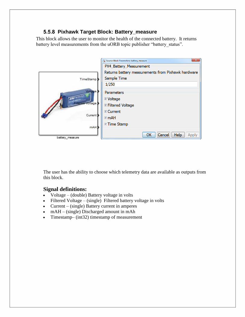
Pixhawk Target Block: Battery_measure
This block allows the user to monitor the health of the connected battery. It returns
battery level measurements from the uORB topic publisher “battery_status”.
The user has the ability to choose which telemetry data are available as outputs from
this block.
Signal definitions: Voltage – (double) Battery voltage in volts
Filtered Voltage – (single) Filtered battery voltage in volts
Current – (single) Battery current in amperes
mAH – (single) Discharged amount in mAh
Timestamp– (int32) timestamp of measurement

Pixhawk Target Block: Binary Logger
Log a vector of double data to a file on the SD card. The first enable port must trigger
high and then low during the execution of the program for a successful write to disk
space. If the enable port does not fall low before the generated code is finished executing
the file will be still considered ‘open’ and not accessible. In order for proper SD card data
writing ensure that the above directory path points to some place in /fs/microsd/
The data input can be a vector signal concatenated together to allow for multiple signal
logging. The signals all need to have the same data type (single).
The format of the log file has a header followed by the binary logged data.
Note that an example model has been provided to showcase data logging and
reading/extraction. Under the examples look for px4demo_log.slx to see how one can use
the logging block and use the px4_read_binary_file function to read in the
logged data file found on the SD card.
Pixhawk Target Block: Example Print Function
Print signal data content to the PX4 Nuttx console terminal. Note that this block should
be treated as an “example” block and the print message can be constructed anyway the
user sees fit. The coder.ceval( ) is a MATLAB Coder function used to evaluate the printf
( ) statement to pass in two values. Please note that there is a bug in Nuttx in which
sometimes floating numbers cannot be properly displayed. Please use warnx( ) instead of
printf( ) of this as a work-around.

Pixhawk Target Block: Read ADC Channels
This block allows one to access the three available external ADC channels on the
Pixhawk.
The user has the ability to choose which ADC channel as outputs from this block
from the 3.3V and 6.6V Analog Input. Note that Channel 1 and 2 corresponds to pin
14 and 15 respectively for the 3.3V ADC. Please see this link for the labelling of the
pins:
https://pixhawk.org/modules/pixhawk
Signal definitions: 3.3V Analog to digital conversion – (int32)
3.3V Analog to digital conversion – (int32)
6.6V Analog to digital conversion (int32)

Pixhawk Target Block: uORB Write
This block allows one to write arbitrary data to a uORB Topic provided that the topic
exists and the structure elements are properly defined. The block assumes that the
topic exists and is defined in the MSG folder here (ie: C:\px4\Firmware\msg). The
block will generate code to include the appropriate header file of the uORB topic. For
instance, if the topic is ‘TOPIC_NAME’ in the first entry, then the header file to be
included:
#include <uORB/topics/TOPIC_NAME.h>
Similarly, the syntax for invoking the uORB Topic and creating its structure will look
like this:
struct TOPIC_NAME_s orb_publish(ORB_ID(TOPIC_NAME), other_param1,
other_param2)
And so on. Please ensure that the topic is well defined and the header / source files
are in the right location.
To specify the struct elements to write to for the uORB topic click on the tick-boxes
and specify the name of the element, the data type and the number of elements to be
greater than one if the struct element is a vector. You can check the dimension and
data type by opening the corresponding .msg file button which will search for the
matching file name in the \px4\Firmware\msg folder.

This block at initialization time will first advertise the topic and then subsequently
publish data from the input signal lines. Note that only a maximum of five struct
elements are accessible at the moment. The next release will explore a more flexible
method of accessing uORB topics.
Signal definitions: To be defined by the user
Pixhawk Target Block: uORB Read / Function-Call Trigger
This block allows one to read arbitrary data from a uORB Topic provided that the
topic exists and the structure elements are properly defined. This block will also allow
one to trigger a function-call signal that will be able to asynchronously execute
generated code when new data from the topic is available. The block cannot act in
these two modes simultaneously.
The block assumes that the topic exists and is defined in the MSG folder here (ie:
C:\px4\Firmware\msg). The block will always generate code to include the
appropriate header file of the uORB topic. For instance, if the topic is
‘TOPIC_NAME’ in the first entry, then the header file to be included:
#include <uORB/topics/TOPIC_NAME.h>
Similarly, the syntax for invoking the uORB Topic and creating its structure will look
like this:
struct TOPIC_NAME_s
orb_read(ORB_ID(TOPIC_NAME), other_param1, other_param2,
etc…)
And so on. Please ensure that the topic is well defined and the header / source files
are in the right location.

The general steps for using this block for reading topics are:
1) Selecting a Topic
This is done with the 2nd button select “uORB Topic msg” which opens up the ‘msg’
directory for you to choose a topic. Only topics which are not treated as C++ objects
are supported, an error message will appear if such topics are chosen. For more details
on this see Chapter 7 on Limitations for a work-around.
2) Creating a bus object
A Simulink bus object is created from the topic in the .msg file. Because uORB topics
are more or less C-structs (except when they are treated as a C++ struct with object
properties) we have the ability to map structs to bus objects. A bus object will appear
in your MATLAB workspace for you to start using. When clicking this button, the data
type output of this block gets automatically assigned to this newly created bus object,
however, you are also free to choose your own as needed.
3) Setting uORB read interval

When reading from a topic, you will also want to specify polling rates (uORB interval)
in milliseconds. Some topics can only provide data at a maximum rate, please ensure
that the polling rate choice does not exceed this.
The general steps for using this block for asynchronous events are as follows:
1) Select Function-Call Trigger
2) Set poll timeout and Task Name
The sample rate at which this block executes at is not applicable when the block is in
Triggered Function-Call mode since the block behaves asynchronously in this
configuration. A Task Name and a polling-time out needs to be specified when in
Triggered Function-Call mode. A new thread is spawned which will be responsible for
running the generated code assosciated with the fucntion-trigger signal. This thread
will wait for new topic data by polling on the topic.
When reading your topic inside the function call trigger block you’ll want to use another
library block “uORB Function-Call Read” we provide to do this. These blocks were
meant to be used together, please see the example px4demo_fcn_call_uorb_example.slx
Signal definitions: To be defined by the user based on bus object

5.6 Example Models
There are several simple “test” models available for you to make sure everything is
correctly installed and working. It is recommended to try one of these initial test models
before trying a complete flight control system model.
IMPORTANT: Simulink does not allow a user to ‘Build’ under the matlabroot (e.g.
c:\MATLAB\R2015b\matlab\toolbox\psp\pixhawk\examples) directory. Therefore it is
recommended to COPY the example models to a user working directory outside the
MATLAB root. There is a copy of these models made at the c:\px4\SimulinkExamples
directory when the PSP is installed. The user can navigate to this directory to work with
the Simulink example models.
px4demo_Parameter_CSC_example.slx
The Pixhawk Px4FMUv2 uses many parameters to store and access during
various operations. Much of these include sensor/actuator calibration data and are
stored in flash memory which is accessible by MTD via NuttX.
You can see the list of default parameters here:
https://pixhawk.org/firmware/parameters
Guide to configuring parameters:
http://dev.px4.io/advanced-configurations.html
The Pixhawk PSP allows you to access these parameters using Embedded Coder's
Custom Storage Class feature. A parameter is first defined in the MATLAB
workspace with specific parameter properties which is then accessed in the
generated code.
To make use of this, use the following syntax:
Pixhawk_CSC.Parameter( CELL_ARRAY )
Where CELL_ARRAY is a MATLAB cell array composed of a value (int32 or
single) and a string of the parameter. For instance:
CAL_GYRO0_XSCALE = Pixhawk_CSC.Parameter( {single(1),
'CAL_GYRO0_XSCALE'} )
Parameters can either be int32 or single/floating precision. Please ensure you select
the correct data type and the the string name matches.
Note that for the model below, all parameters have been defined in the model
callback function
NOTE: This model is to be demonstrated using external mode
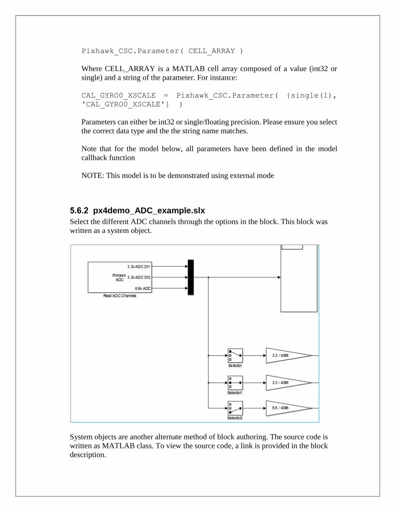
px4demo_ADC_example.slx
Select the different ADC channels through the options in the block. This block was
written as a system object.
System objects are another alternate method of block authoring. The source code is
written as MATLAB class. To view the source code, a link is provided in the block
description.

NOTE: This model is to be demonstrated using external mode
px4demo_input_rc.slx
This model will test the RC transmitter block. Use the RC Transmitter to control the
color and mode of the RGB LED on the pixhawk. Channel 3 is typically the “Thrust”
or the left vertical joystick control. Channel 4 is typically the “Yaw” or the right
horizontal joystick control.
px4demo_rgbled.slx
A simple model that show how to program the RGB_LED library block. Every
second the RGB LED changes from blinking-fast blue color to “breathing” red color.
px4demo_tune.slx
To test various tunes, this model plays all the pre-defined tunes plus a user-custom
tune cycling every 10 seconds.

px4demo_gps.slx
A test model has been provided to test out the GPS Block. This model will print out
information to a terminal window once a second and the RGB LED will “breathe”
Green. You will need to establish a serial terminal connection to the PX4 hardware
with a program such as TerraTerm or PuTTY. If you do not manually start the
px4_simulink_app (rather have it start at boot-up time), then you will need to stop it,
then re-start it with these commands (since there is no stdout console available at
boot-up time the printf statements in the code can’t output any text):
nsh> px4_simulink_app stop
then
nsh> px4_simulink_app start
The output will look similar to this:
The top-level model is simple. The Display Subsystem has a MATLAB Block which
shows how to print information (text strings) to the console if you want to include
some debug outputs in your model. User should be careful not to run any standard
output to the console at the high base rate, but rather put it in a slower rate (e.g. 1

second sample time) as illustrated with the different colors in the model (Red = fast
rate, Green = slow rate).
px4demo_attitude_plant.slx
In order to design and simulation your flight control you will need a test-bench
model. It is recommended that you create your test bench model that will provide the
stimulus and plant/environment/feedback behavior for your flight control and use a
Model (Reference) Block for your control system model.
Here is an example of a model to simulate an attitude control system:

px4demo_attitude_control.slx
This model contains the heart of the attitude flight control model. It should have the
identical configuration parameters as the parent model.

px4demo_attitude_system.slx
After the flight control system has been successfully simulated, it can be used in an
“implementation” model that the user can use to generate code and deploy to the
Pixhawk PX4 hardware.
Here is the same Control Model referenced in a system model for deployment. The
RED/GREEN colors indicate the different sample rates of the model (RED = 250Hz,
GREEN = 2Hz).
px4demo_fcn_call_uorb_example.slx
This model demonstrates a function-call subsystem approach to modeling using
triggered subsystems. This can be used to model this type of control architecture seen
here:
https://github.com/PX4/Firmware/blob/master/src/modules/mc_att_control/mc_att_co
ntrol_main.cpp
In this scheme, the control algorithm is driven by sensor updates. A variable is used
to keep track of the time between updates such that the control terms such as
Derivative and Integral can be computed accurately. Although these sensor updates
are configured to come in at regular intervals, this approach accounts for any small
differences in time due to jitter imprecision.
Inside the function-call subsystem, we read out the data from the sensor update event
from a source block. The data can then be subsequently processed upon reception of
the data. Because of this control structure, this event-driven control logic is
considered to be asynchronous. If you check the sample times of the model you can
see that this subsystem is configured this way.

NOTE: This model is to be demonstrated using external mode
px4demo_write_uorb_example.slx
This model demonstrates how one can write data to uORB topics. The uORB write
block writes to the struct elements 'lat','lon' and 'timestamp' to the GPS topic. The
GPS block then outputs the same value we are writing to by first advertising the GPS
topic and then publishing data. You can define whatever topic to write to and its
individual struct elements
1) Define LAT, LON and TIME in the MATLAB work-space with assigned values.
Ensure they are matching data types to what the block expects.
2) Run in external mode
3) Tune values LAT, LON and TIME and watch the values change in the display
from the output of the GPS block

NOTE: This model is to be demonstrated using external mode
Serial Communication
Two models have been provided to demonstrate how to setup serial communication
px4demo_HostSerial_TxRx.slx
This model does not undergo code generation, it resides on the host PC and is
responsible for sending/receiving data to the Pixhawk Px4FMU over serial. The
scopes will show accelerometer and gyro readings. A loopback display block is used
to show the value that we send to the Pixhawk is sent back.

px4demo_Serial_TxRx.slx
This model is the one that will be deployed the Pixhawk FMU. It will fetch data from
a uORB topic and send it off over serial (ttyS6). Loopback data is received and sent
back into the serial send block.
6 Building your own custom Simulink Block
There are several reasons you may want to consider building your own Simulink block.
The most common reason is the need to interface generated code with custom code.
This could be to interface with driver code which talks to various sensors/actuators or
to send data over to another interface. Whatever the reason may be, MATLAB and
Simulink offers many ways to accomplish the same goal here.
S-Function Approach
All the blocks in this Pilot Support Package were created by writing S-functions with
TLC and System Objects.
There are many ways to create S-Functions and the accompanying TLC code.
Write it by hand along with the TLC from scratch
Use S-function builder
Use Legacy Code Tool to interface to existing hand-written code.
Use a combination of all of the above. S-function builder or Legacy Code Tool can
be used to create a starting point for you to start modifying the S-function MEX
source file as well as the TLC.

We have provided an example in this version of the PSP (C-MEX and TLC) for users
to learn from. Please See:
\examples\BlockCreation\
Apply the MEX command on the sfun_px4_battery_example.cpp block to generate a
valid MEX file for the S-function. Use this block as an example as to how to create
blocks with S-Functions.
For more documentation on S-Functions, please see:
http://www.mathworks.com/help/releases/R2016a/rtw/block-authoring.html
MATLAB Function blocks and System Objects
The logging block was written using a MATLAB Function block. MATLAB Coder
syntax is used to describe the interface to hand-code. Please examine the contents of
this block for more information on how this was accomplished
Another method that exists is through the use of System Objects. These types of blocks
make use of MATLAB Coder’s capability of transforming MATLAB Code into C-
code. System Objects are written using an object-oriented approach. Please see the
ADC and Serial blocks as examples of how to write such blocks.
Click on the ‘Source code’ hyperlink to open up the MATLAB System Object code for
these types of blocks.
For more information on MATLAB Coder and System Objects, please also see:
https://www.mathworks.com/help/simulink/ug/creating-an-example-model-that-uses-a-matlab-
function-block.html
https://www.mathworks.com/help/simulink/slref/coder.ceval.html
https://www.mathworks.com/help/simulink/system-objects.html

7 Limitations Also, the supplied Simulink blocks do not support any simulation behavior.
These are merely there to provide code generation to interface the control system
to the actual hardware drivers necessary in the firmware. It is advised that you
use Model Referencing to separate your control system so that you can re-use the
model in your simulation as well as the implementation model (used for code
generation).
Currently, the optimization option “Inline Parameters” must be turned on. This
eliminates the use of global data being created which has shown to cause
compilation errors due to limited global memory space.
Support for HIL / Mavlink
We currently do not support interactions with HIL or Mavlink with the
px4_simulink_app. This is something we wish to investigate in the future and will
require significant changes / updates to the way we generate code for this
application. Additional code will need to be added to each of the blocks to allow
routing of signals when in a HIL environment. If you have suggestions or
contributions to help in this area, please feel free to reach out to MathWorks Pilot
Engineering.
Supporting C++ uORB Message Data Structures
The current uORB read block is only able to convert uORB messages into
Simulink bus objects if the topic is not treated as a C++ object. Several messages
are treated as a C++ object where the data structure will not be compatible in C.
At the moment, we only generate C code for px4_simulink_app. This means that
thing such as memcopies or memory layout cannot be assumed to be contagious.
Here’s an example of a uORB topic that uses C++ notation.
Message File: battery_status.msg
uint64 timestamp # microseconds since system boot, needed to integrate
float32 voltage_v # Battery voltage in volts, 0 if unknown float32 voltage_filtered_v # Battery voltage in volts, filtered, 0 if unknown
float32 current_a # Battery current in amperes, -1 if unknown float32 current_filtered_a # Battery current in amperes, filtered, 0 if unknown
float32 discharged_mah # Discharged amount in mAh, -1 if unknown
float32 remaining # From 1 to 0, -1 if unknown
int32 cell_count # Number of cells bool connected # Wether or not a battery is connected
#bool is_powering_off # Power off event imminent indication, false if
unknown
uint8 BATTERY_WARNING_NONE = 0 # no battery low voltage warning active uint8 BATTERY_WARNING_LOW = 1 # warning of low voltage
uint8 BATTERY_WARNING_CRITICAL = 2 # alerting of critical voltage
uint8 warning # current battery warning

The header file which gets generated looks something like this: C:\px4\Firmware\build_px4fmu-v2_default\src\modules\uORB\topics\battery_status.h
#ifdef __cplusplus
struct __EXPORT battery_status_s {
#else
struct battery_status_s {
#endif
uint64_t timestamp;
float voltage_v;
float voltage_filtered_v;
float current_a;
float current_filtered_a;
float discharged_mah;
float remaining;
int32_t cell_count;
bool connected;
uint8_t warning;
#ifdef __cplusplus
static const uint8_t BATTERY_WARNING_NONE = 0;
static const uint8_t BATTERY_WARNING_LOW = 1;
static const uint8_t BATTERY_WARNING_CRITICAL = 2;
#endif
};
Because the battery_status uORB topic was written in C++ we see non-C struct
notation with BATTERY_WARNING_NONE, BATTERY_WARNING_LOW and
BATTERY_WARNING_CRITICAL. Because the PixhawkPSP generates C code we
cannot assume instantiate this struct and copy data elements such as
BATTERY_WARNING_NONE over like a normal C struct without getting a compiler
error. These variables must be treated as a ‘singleton’ or global.
We have provided a block which is similar to the uORB read block in the current
library but supports the ability to access struct elements from a C++ uORB object,
however, the ability to actually read the global elements is not supported. Please
look at the example inside: \blocks\ExtraLibSupport
Example:

However, attempting to do this:
Will result in compiler error. Therefore, the official shipped version of the uORB
read block that uses bus objects will reject these types of data structures completely
while this version of the block will still allow you to use any data structure.
If you wish to support the C++ global member variables such as the one in the
example above, you will probably need to write your own block that does a copy
of data from a C++ struct into local C variables. This function/code could live inside
a C++ source file and gets used only if the topic will contain C++ data-structures.
Consult the previous chapter on block creation for more tips on how to do this as
well. This may be addressed in a future version of the PSP.
8 Updating to a new version of Pixhawk PSP There may be times when a new version of the Pixhawk PSP will need to be
installed. This could be based on newer versions of Simulink being released, bug
fixes, new blocks or enhancements of both the base product and the PSP.
If you run into any issues with the use of this PSP please contact your MathWorks
sales representative or Pilot Engineering group directly. Do not go through
technical support for issues with this PSP. Do go through technical support for
issues related to MATLAB/Simulink outside the scope of this PSP.

9 Using External Mode with the Pixhawk PSP
9.1 What is External Mode?
External mode is a way in which one can examine execution and “tune” the generated code
from your standard desktop environment. This feature comes with Embedded Coder and
can greatly enhance debugging capabilities or interactive testing through tuning of model
parameters. For instance, suppose you wanted to know the output value of a certain signal
at each time step of the simulation. One could implement this by modifying the generated
code to execute a “printf” of that signal value manually or create a block to do this (we
actually provide this for you), however, this can be cumbersome. External mode can
alleviate this by not only displaying the value of the signal from the generated code in a
scope in the Simulink environment, but it also enables you to log that signal and record it
to your host PC as a MAT file as well. One way to think of external mode is that your
Simulink model now becomes a “user-interface” that interacts with the generated code
during execution, instead of the play button playing a simulation on your host machine the
play button now begins execution of embedded code.
Communication
Channel
Simulink Model
External
Mode
Client
(ExtMex)
External
Mode
Server
Target
Generated Code from Simulink Model
Host
PC

This mode is not to be confused with Hardware-in-the-Loop or Processor-in-the-Loop.
External mode works by establishing a communication channel between the host PC and
the embedded system you are targeting. MathWorks provides all the necessary source files
for both TCP/IP and Serial communication – in the case with the Px4FMU we are using
serial communication.
The generated code and the Simulink infrastructure have the necessary source files and
shared libraries to do this for you without having you manually modify the code itself.
For more information, please see:
http://www.mathworks.com/help/rtw/ug/external-mode-communication_f1028013.html
9.2 Some important considerations:
External mode can be a potentially taxing process since it needs to transfer data back and
forth to the PC as well as wait for user commands to start/stop execution of the model as
well as tuning of parameters. Because of the limited resources on the Px4FMU, it is highly
recommended to NOT use external mode for flight tests. Due to limited RAM on the
system, the amount of data transferred back must be reduced considerably at each
execution time-step, therefore, some special modifications to some user settings must be
made. More detail will be covered on this down below.
Note that if you are just interested in logging data rather than viewing data as the system is
running and tuning parameters then you may want to consider data logging. A Simulink
block is being developed for this in the Pixhawk Library browser.
Important Note: Recent testing has confirmed that external mode does not operate
correctly with the telemetry radios. Data comes in very sporadically and in long intervals.
We are looking into this and will provide an update to address the issue, in the mean-time,
please use USB for serial connection for external mode.
10 External Mode Tutorial Part 1:
10.1 Viewing Signals from the generated Code
Serial port setup:
Before running External Mode, you should be familiar with the serial ports offered by the
hardware. The Px4FMUv2 comes with a variety of different options. To see which serial
ports you may want to use consult these pages here:
https://pixhawk.org/users/wiring https://pixhawk.org/dev/wiring

Note: some serial ports are reserved and cannot/should not be used, such as ttyS0 which is
a serial debug console port. Please consult above links for information on this.
Suppose you wanted to use the standard USB programming cable for external mode. In
this case, ttyACM0 becomes a free serial port to be used by external mode and ttyS6 be a
serial console shell. Here is one example of one would modify their rc.txt file to do this:
#sercon - in the latest release sercon already gets called
usleep 1000
uorb start
usleep 1000
#nshterm /dev/ttyACM0 & #Disable the USB serial console
usleep 1000
px4io start
usleep 1000
#commander start
#usleep 1000
#mavlink start -d /dev/ttyS1 -b 115200
#usleep 5000
#dataman start
#usleep 1000
#navigator start
#usleep 1000
sh /etc/init.d/rc.sensors
usleep 1000
#sh /etc/init.d/rc.logging
#usleep 1000
#gps start
#usleep 1000
#attitude_estimator_ekf start - the latest release does not use this anymore
ekf_att_pos_estimator start
usleep 1000
#attitude_estimator_so3 start
#usleep 1000
#mavlink start -d /dev/ttyS3 -b 115200
mtd start
usleep 1000
param load /fs/mtd_params
usleep 1000
rgbled start
usleep 1000
#px4_simulink_app start #disable automatic starting up of the model
nshterm /dev/ttyS6 & #this will make ttyS6 the serial console
exit
In the above example, ttyS6 (serial port 4) and the USB port we typically use to access the
serial console is now a free serial port we can use to establish data exchange in external
mode. Note that in the example I am doing in this tutorial, I have ttyS6 connected to a USB
FTDI connector which will allow my Windows machine to access the serial shell over USB.
Other options could include using the telemetry radios to establish external mode which
would be different serial ports than the ones mentioned here.–

10.2 Model Configuration Setup:
The next step after choosing a serial port is to now configure Simulink to use the port of
choice. Open up the model
ext_mode_intro.slx
To configure Windows to talk to the Px4FMU, click on the interfaces section in Code
Generation, then click on Interface, then under MEX-file Arguments you want to type in
the following syntax
1 <COMPORT#> <BAUDRATE> <TIMEOUT>
The ‘1’ value in the front is to indicate that the generated code will wait for the host
before starting execution. This is highly recommended.
<COMPORT#> - this is the COM port of the USB connection which connects the PC and
the Px4FMU
<BAUDRATE> - Specify a baud rate here. Note that radios are set to run on 57600
<TIMEOUT> - Specify the amount of time it takes to wait for establishing a connection
before timing out. 5 seconds should be sufficient
Next, we want to configure the generated code to use the correct serial port on the
firmware. In this example, this is ttyACM0

Click on the Coder Target menu and then select external mode options. Click on the Baud
Rate Select button drop-down to select a baud rate and specify the data exchange serial
port as ‘ttyACM0’
10.3 Running the example model
The next step is to run the model. This involves a couple of steps:
1) Pressing the build button (ctrl+B) to generate code, compile it, and then having it
transferred to the PX4FMU
2) Running the model. Open up the serial shell to access the command line and start
the model by typing ‘px4_simulink_app start’
The model will not actually begin execution yet until receiving a start packet from
external mode, this is done in the next step
3) Ensure that the drop-down menu is set to ‘External’
After, click on the “Connect To Target” button on the left of the above diagram.
This will establish connection after a few seconds. Finally, press the green play
button to the right. You will now be able to see data appear in the Simulink model
in the generated code.

4) To stop the generated code, press the stop button in the model. If you wish to run
external mode again, type ‘reboot’ at the serial console as well. There is
currently a limitation in which external mode code has some issues being treated
as re-entrant. This will be fixed in the future – for now, please reboot the
Px4FMU in-between external mode runs.
11 External Mode Tutorial Part 2: External Mode Control Panel
As mentioned earlier, the PX4FMU runs on a resource constrained environment. External
mode can be process intensive at times depending on the circumstances. For instance, if
you have a model which contains many (10-30) scopes the amount of data transferred can
impact real-time performance. To assist with real-time execution of code, external mode
has been automatically configured to run as a back-ground task by default. This option
appears in the External Mode Control panel and doesn’t need to be changed by the user.
Due to limited memory, the amount of data that can be transferred back needs to be
adjusted. This setting dictates a buffer size on the Px4 for each signal you are logging.

When clicking on the “Signal & Triggering” button you get access to all the signals that
are attached to display ports. Signals marked with an X are available for viewing in
external mode which you can enable/disable with the “ON” and “OFF” radial button on
the right. The diagram below has the “select all” option enabled so all display/scopes will
be viewable.
The ‘Duration’ value specifies the buffer size to send back to Simulink. The default value
of 10000 is rather large, so in this example we have scaled it back down to 1000. A large
value can impact performance of external mode – the real-time code can still run but
external mode may not report back on time. Since external mode runs on a lower priority
task the generated code from Simulink takes more precedence and can potentially delay
external mode’s transfer of data to the host machine. To avoid this, choosing a low
duration value such as 1000 or 500 samples can help greatly.

Duration value dictates how many samples you’ll see at each time step in the Simulink
model. Duration value does not apply to all sample times, since it is based on the base-
sample rate. In other words, choosing a value of 1000 means one will receive 1000 data
‘ticks’ of base-rate data. Here is an example:
Suppose we have a model and its fastest-sample time is 250 Hz (Ts = 0.004 seconds) and
a slower rate 25 Hz (Ts = 0.04 seconds)
Suppose we choose a duration value of 400:
This means if we hook a scope up to a 250 Hz signal we will see 400 sample points
appear at a time in external mode. Or in other words, (400*0.004 = 1.6 seconds) 1.6
seconds of data will appear at a time.
For the lower sample rate (25 Hz), 1.6 seconds of data yields 40 data points (1.6/0.04 =
40 ) at a time rather than 400
One should be careful to not choose a duration time that is too low. For instance, suppose
I chose a duration time of 1. This means:
250 Hz: Any scope hooked up to this will give you one sample at a time
1*0.004 = 0.004 seconds of data
0.004 / 0.04 = 0 (round to floor)
A duration size must be selected which is big enough such that each time external mode
delivers data back to the PC it has enough sample points for signals running on a lower
sample-rate. If we chose a duration value of 1 only the 250 Hz signal will display data
and the other signals will show no data (default value of zero)
11.3 Tips for logging fast-rate signals
Sometimes, depending on the model, there will be a noticeable delay when receiving
data. This can occur if the signal if you are trying to log is running at a fast sample rate.
External mode may deliver data back to the PC at a slower than desirable rate. One way
to get-around this is to use a rate transition block to view a signal running at a fast rate at
a slower rate. You will get less data back but this will help alleviate slow-downs –
considerations and trade-offs will need to be made depending on the situation
In this example I specify a sample rate of the sensor block to 250 Hz.
If you just want sensor data, you can just hook up a scope and start logging away,
however, keep in mind that you will not get real-time performance. This means that the

Simulink timer assosicated with the base-rate ticks will not keep up with real-time. Data
coming in from the sensors will still update/react to physical stimuli but the time stamp of
data will not be in real-time (ie: 2-3 times slower). Other sample rates will suffer as a
result and not run on schedule. Performance is affected at the cost of getting more data
back into the host PC.
Adding in the rate transition to slow down the sampling will help greatly as shown above.
px4demo_attitude_system_multi_task.slx
11.4 Background Task vs Normal EXT Mode Behavior
This model has already been configured to use a background task and already uses a lot of the tips
described in the above steps. With background tasking, the base-rate task is not encumbered by
having to run external mode tasks at the same time, instead, EXT mode is now running in the
background on another task being paced at 10 Hz. This can greatly help with real-time
performance. Sometimes you may want to use the default behavior if you only have a single
sample-time running at a slow rate - if you want data to come in faster or as fast as the model's
sample-time then you'll want to use default behavior. On the other hand, if your model is running
with multiple rates at varying speeds, you will want to pick the back-ground task option
12 External Mode Tutorial Part 3: Tuning parameters
Tuning parameters is one way to adjust values of the generated code Simulink while
execution. In order for this to be possible, parameters must be set to tunable. Tunable
parameters allow parameters to be exposed in the generated code as a global value such
that an external program can have more control over it rather than having it inlined.
Due to resource constraints in global memory, parameters all Pixhawk PSP models are
set to inline and will error out if you disable the inline parameter option. You can,
however, select certain parameters to allow for tuning. This is done by clicking on the
configure button in this menu
Configuration Parameters -> signals and parameters -> inline parameters -> configure
The example model for this section is : parameter_tune.slx

From this menu, you can now select parameters you wish to tune. Note that a parameter
that requires tuning must have a parameter which exists in the base-workspace. In this
example, the parameter is ‘TuneGain’ which has been selected.
To change the value of this parameter while the Simulink model is running, change the
value in the base MATLAB workspace, to update the model and then bring up the
External Mode Control panel
Now, press the “Download” button to push updated parameter values onto the generated
code with “Batch download” selected

If you have multiple parameters that change, clicking the download button will also
update those parameters in one-shot. In the above example I change the TuneGain from -
1 to -2 and the generated code receives this update immediately afterwards. Note a faster
method is to also update the model diagram by pressing CTRL+D after changing a
parameter in the MATLAB command prompt.