PITCHED ROOF SUN TUNNEL INSTALLATION INSTRUCTION · PITCHED ROOF SUN TUNNEL INSTALLATION...
10
www.addlite.co.uk PITCHED ROOF SUN TUNNEL INSTALLATION INSTRUCTION Please leave these installation instructions with the owner of the Sun Tunnel. This will enable them to carry out the straightforward maintenance mentioned below. Dispose of all packaging carefully and responsibly. The Sunlume Sun Tunnel is designed to be maintenance free and the shape of the dome and the flashing is designed to be self-cleaning. If for any reason, further cleaning is required, only warm, soapy water should be used to wash the external dome and flashing. Take great care not to scratch the dome when washing. Internal cleaning should not be required since all components are effectively ‘sealed-for-life’. Sunlume Sun Tunnel has a 10 year guarantee against any defects arising due to faulty materials. Scaffolding For pitched roofs and two-storey buildings a tower scaffold or similar should be provided to gain access to the roof if it is greater than 10ft. (3m) in height from ground level and not more than 20ft. (6m) in height. For access to roofs greater than 20ft. (6m) in height a professionally installed scaffold access should be provided. All scaffolding and ladders must be properly fixed to the building and all necessary precautions must be taken to prevent falling materials and provide a safe working environment for personnel. 1. Preparation and safety information Electricity Normal safety precautions should always be followed. A low voltage power supply should be used when appropriate. Care should be taken to ensure there are no wires, cables, leads, water or gas pipes near the work area. Suitable eye protection and protective gloves must be worn. Cutting Sun Tunnel tubes can be sharp after their ends are cut with tin snips, protective gloves must be worn. Dust A safety mask should be worn to ensure you don’t inhale dust when carrying out the installation of a Sunlume system. Other safety recommendations Do not install Sunlume Sun Tunnels when it is raining or the roof area is wet or slippery. You will need the following equipment: Protective eyewear, protective gloves, protective breathing mask, ladders, tin snips, power drill, power jig-saw, dispensing gun to dispense the silicone sealant supplied, miscellaneous other tools. Building Regulations Always check with your local council that your installation complies with all local Building Authority requirements. © 2014 Surespan Ltd. All rights reserved Tel: 01922 711185 • Email: [email protected] • www.addlite.co.uk Leamore Close • Leamore Enterprise Park • Walsall • WS2 7NL • West Midlands • UK 1
Transcript of PITCHED ROOF SUN TUNNEL INSTALLATION INSTRUCTION · PITCHED ROOF SUN TUNNEL INSTALLATION...

www.addlite.co.uk
PITCHED ROOF SUN TUNNEL INSTALLATION INSTRUCTION
Please leave these installation instructions with the owner of the Sun Tunnel. This will enable them to carry out the straightforward maintenance mentioned below.
Dispose of all packaging carefully and responsibly.
The Sunlume Sun Tunnel is designed to be maintenance free and the shape of the dome and the flashing is designed to be self-cleaning. If for any reason, further cleaning is required, only warm, soapy water should be used to wash the external dome and flashing. Take great care not to scratch the dome when washing. Internal cleaning should not be required since all components are effectively ‘sealed-for-life’.
Sunlume Sun Tunnel has a 10 year guarantee against any defects arising due to faulty materials.
Scaffolding
For pitched roofs and two-storey buildings a tower scaffold or similar should be provided to gain access to the roof if it is greater than 10ft. (3m) in height from ground level and not more than 20ft. (6m) in height.
For access to roofs greater than 20ft. (6m) in height a professionally installed scaffold access should be provided. All scaffolding and ladders must be properly fixed to the building and all necessary precautions must be taken to prevent falling materials and provide a safe working environment for personnel.
1. Preparation and safety information
Electricity
Normal safety precautions should always be followed.A low voltage power supply should be used when appropriate. Care should be taken to ensure there are no wires, cables, leads, water or gas pipes near the work area. Suitable eye protection and protective gloves must be worn.
Cutting
Sun Tunnel tubes can be sharp after their ends are cut with tin snips, protective gloves must be worn.
Dust
A safety mask should be worn to ensure you don’t inhale dust when carrying out the installation of a Sunlume system.
Other safety recommendations
Do not install Sunlume Sun Tunnels when it is raining or the roof area is wet or slippery.
You will need the following equipment:
Protective eyewear, protective gloves, protective breathing mask, ladders, tin snips, power drill, power jig-saw, dispensing gun to dispense the silicone sealant supplied, miscellaneous other tools.
Building Regulations
Always check with your local council that your installation complies with all local Building Authority requirements.
© 2014 Surespan Ltd. All rights reserved Tel: 01922 711185 • Email: [email protected] • www.addlite.co.ukLeamore Close • Leamore Enterprise Park • Walsall • WS2 7NL • West Midlands • UK 1

www.addlite.co.uk
Sun Tunnel crimped end connecting pieceMust be used at roof level (cut to length on site) 3 section 45° adjustable elbow For steeper roof slopes over 45° you will require 2 x 30° elbows
Plain end Sun Tunnel 610 mm Must be used to terminate above ceiling level
3 mm plywood backing panel And marking out template Fixing ring To be fitted to ceiling opening Sun Tunnel bell endSlides over end of plain end pipe above ceiling level
Ceiling diffuserOpal or prismatic Clip on Diffuser trim In white as standard
2. Components for a standard kit installation of a Diamond dome in a Pitched Roof
610mm extension length with crimped end
2 section 30° adjustable elbow Used where a small offset is required includes 5 x 3.2mm x 10mm pop rivets for assembly of 450mm and 530mm elbows
3 section 45° adjustable elbow For large offsetsincludes 10 x 3.2mm x 10mm pop rivets for assembly of 450mm and 530mm elbows
15 x 15mm self tapping stainless steel screws5 for fixing the collar to the flashing plate, 4 for fixing the pipe, 5 x for fixing the dome to the ABS collar, 1 x spare
13 x 35mm or 45mm screws (depending on size)5 x for fixing the diffuser, 8 x for fixing the Flashing plate
10 x Black washers5 x for use when fixing the Dome, 4 x for use when fixing the Collar to the Flashing plate, 1 x spare.
Silicone sealant (not to be used on lead flashings) Silver aluminium tape
© 2014 Surespan Ltd. All rights reserved Tel: 01922 711185 • Email: [email protected] • www.addlite.co.ukLeamore Close • Leamore Enterprise Park • Walsall • WS2 7NL • West Midlands • UK 2
Optional additional components
Installation pack
Polycarbonate diamond dome
Brushed nylon condensation sealing gasket
ABS flashing plate for slate pitched roof
ABS undercloak roofing felt support
Alternative components
ABS flashing Weathering skirt and weathering foam for plain tiled roofs (includes fixings)
Lead flashing For bold rolled tile roofs (includes lead sealant for lead flashing only)
ABS collar For use with lead flashing(includes fixings)
www.addlite.co.uk
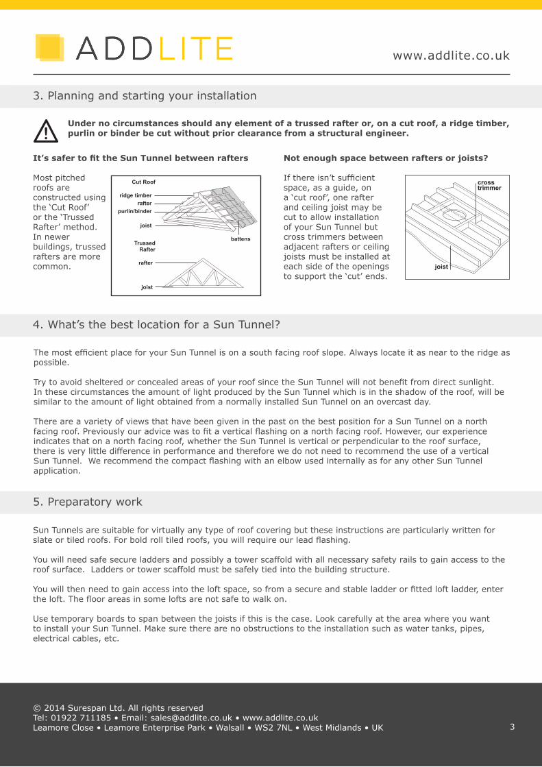
Under no circumstances should any element of a trussed rafter or, on a cut roof, a ridge timber, purlin or binder be cut without prior clearance from a structural engineer.
It’s safer to fit the Sun Tunnel between rafters Most pitched roofs are constructed using the ‘Cut Roof’ or the ‘Trussed Rafter’ method. In newer buildings, trussed rafters are more common.
3. Planning and starting your installation
Not enough space between rafters or joists? If there isn’t sufficient space, as a guide, on a ‘cut roof’, one rafter and ceiling joist may be cut to allow installation of your Sun Tunnel but cross trimmers between adjacent rafters or ceiling joists must be installed at each side of the openings to support the ‘cut’ ends.
Sun Tunnels are suitable for virtually any type of roof covering but these instructions are particularly written for slate or tiled roofs. For bold roll tiled roofs, you will require our lead flashing.
You will need safe secure ladders and possibly a tower scaffold with all necessary safety rails to gain access to the roof surface. Ladders or tower scaffold must be safely tied into the building structure.
You will then need to gain access into the loft space, so from a secure and stable ladder or fitted loft ladder, enter the loft. The floor areas in some lofts are not safe to walk on. Use temporary boards to span between the joists if this is the case. Look carefully at the area where you want to install your Sun Tunnel. Make sure there are no obstructions to the installation such as water tanks, pipes, electrical cables, etc.
© 2014 Surespan Ltd. All rights reserved Tel: 01922 711185 • Email: [email protected] • www.addlite.co.ukLeamore Close • Leamore Enterprise Park • Walsall • WS2 7NL • West Midlands • UK
!
crosstrimmer
joist
5. Preparatory work
Cut Roof
ridge timberrafter
purlin/binder
joist
Trussed Rafter
rafter
joist
battens
4. What’s the best location for a Sun Tunnel?
The most efficient place for your Sun Tunnel is on a south facing roof slope. Always locate it as near to the ridge as possible.
Try to avoid sheltered or concealed areas of your roof since the Sun Tunnel will not benefit from direct sunlight. In these circumstances the amount of light produced by the Sun Tunnel which is in the shadow of the roof, will be similar to the amount of light obtained from a normally installed Sun Tunnel on an overcast day.
There are a variety of views that have been given in the past on the best position for a Sun Tunnel on a north facing roof. Previously our advice was to fit a vertical flashing on a north facing roof. However, our experience indicates that on a north facing roof, whether the Sun Tunnel is vertical or perpendicular to the roof surface, there is very little difference in performance and therefore we do not need to recommend the use of a vertical Sun Tunnel. We recommend the compact flashing with an elbow used internally as for any other Sun Tunnel application.
3

Determine where you want the Sun Tunnel to be positioned in the ceiling and where you want it to exit through the roof. For best results, try to position the dome directly above your chosen location of the ceiling diffuser not forgetting to allow for the elbow offset.
To aid the positioning you can place the plywood template at the chosen diffuser position and pre-assemble the first pipe(1), elbow(2) and second pipe(3) together (as shown).
Mark the diffuser position by drilling a small hole through the centre of the plywood template(x).
Push a screwdriver through the internal felt, and out through the external roof covering at the chosen location for dome. This will lift the tiles and make it easier to see where you need to enlarge the hole for the Sun Tunnel.
www.addlite.co.uk
6. Positioning the Sun Tunnel
Establish the position in which the Sun Tunnel is to be installed by locating the screwdriver inserted from inside. Remove the tiles or slates from around the area and set aside.
Temporarily place the flashing plate in position so that it is centred over the pilot hole. Remove sufficient tiles to mark and cut back the battens and cut diagonals in the felt covering to allow for the installation of the pipe. Refer to the table below to determine the size of the hole to mark. (Tip: you can also use the flashing plate to mark the hole size and position)
© 2014 Surespan Ltd. All rights reserved Tel: 01922 711185 • Email: [email protected] • www.addlite.co.ukLeamore Close • Leamore Enterprise Park • Walsall • WS2 7NL • West Midlands • UK 4
7. Removing the tiles or slates
8. Fitting the ABS Undercloack
The ABS undercloak felt support plate is used to hold the roof felt in position to prevent it drooping. Once the position of the Sun Tunnel has been determined and the felt cut, trim the ABS undercloak with a stanley knife to fit between the rafters then push up the undercloak support plate towards the underside of the roof to make the roofing felt in a taut condition. Fix the support plate in position by screwing to the existing roof batons.
Alternatively, two additional noggings can be screw fixed into the rafters to support the ABS undercloak plate.
elbow offset
1
2
3
X
use a tile to gauge the position of the flashing
plate, as shown
Nominal Diameter Actual
DiameterStructural Opening
230mm 9” (230mm) 240mm300mm 12” (305mm) 315mm450mm 18” (458mm) 470mm530 mm 21” (536mm) 550mm
www.addlite.co.uk
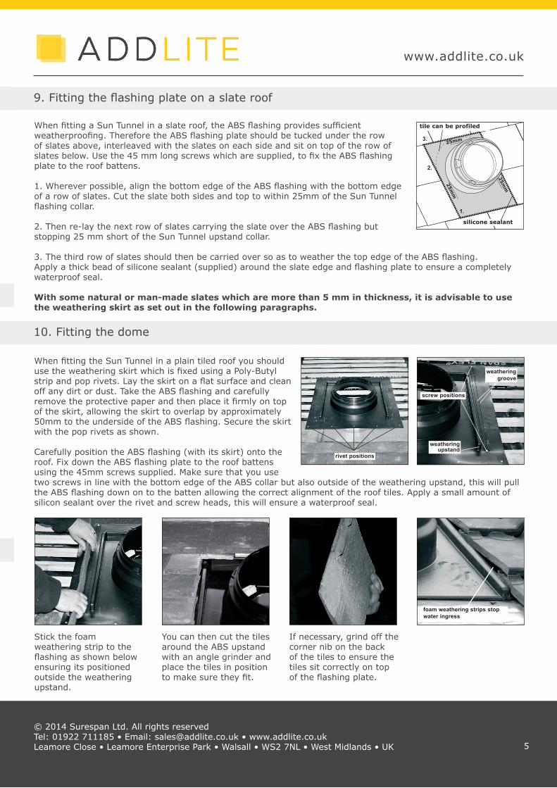
When fitting a Sun Tunnel in a slate roof, the ABS flashing provides sufficient weatherproofing. Therefore the ABS flashing plate should be tucked under the row of slates above, interleaved with the slates on each side and sit on top of the row of slates below. Use the 45 mm long screws which are supplied, to fix the ABS flashing plate to the roof battens.
1. Wherever possible, align the bottom edge of the ABS flashing with the bottom edge of a row of slates. Cut the slate both sides and top to within 25mm of the Sun Tunnel flashing collar.
2. Then re-lay the next row of slates carrying the slate over the ABS flashing but stopping 25 mm short of the Sun Tunnel upstand collar.
3. The third row of slates should then be carried over so as to weather the top edge of the ABS flashing.Apply a thick bead of silicone sealant (supplied) around the slate edge and flashing plate to ensure a completely waterproof seal.
With some natural or man-made slates which are more than 5 mm in thickness, it is advisable to use the weathering skirt as set out in the following paragraphs.
9. Fitting the flashing plate on a slate roof
When fitting the Sun Tunnel in a plain tiled roof you should use the weathering skirt which is fixed using a Poly-Butyl strip and pop rivets. Lay the skirt on a flat surface and clean off any dirt or dust. Take the ABS flashing and carefully remove the protective paper and then place it firmly on top of the skirt, allowing the skirt to overlap by approximately 50mm to the underside of the ABS flashing. Secure the skirt with the pop rivets as shown.
Carefully position the ABS flashing (with its skirt) onto the roof. Fix down the ABS flashing plate to the roof battens using the 45mm screws supplied. Make sure that you use two screws in line with the bottom edge of the ABS collar but also outside of the weathering upstand, this will pull the ABS flashing down on to the batten allowing the correct alignment of the roof tiles. Apply a small amount of silicon sealant over the rivet and screw heads, this will ensure a waterproof seal.
© 2014 Surespan Ltd. All rights reserved Tel: 01922 711185 • Email: [email protected] • www.addlite.co.ukLeamore Close • Leamore Enterprise Park • Walsall • WS2 7NL • West Midlands • UK
10. Fitting the dome
tile can be profiled
1.
2.
3.
silicone sealant
25mm
25mm
25mm
screw positions
weathering upstand
weathering groove
rivet positions
foam weathering strips stop water ingress
Stick the foam weathering strip to the flashing as shown below ensuring its positioned outside the weathering upstand.
You can then cut the tiles around the ABS upstand with an angle grinder and place the tiles in position to make sure they fit.
If necessary, grind off the corner nib on the back of the tiles to ensure the tiles sit correctly on top of the flashing plate.
5
www.addlite.co.uk
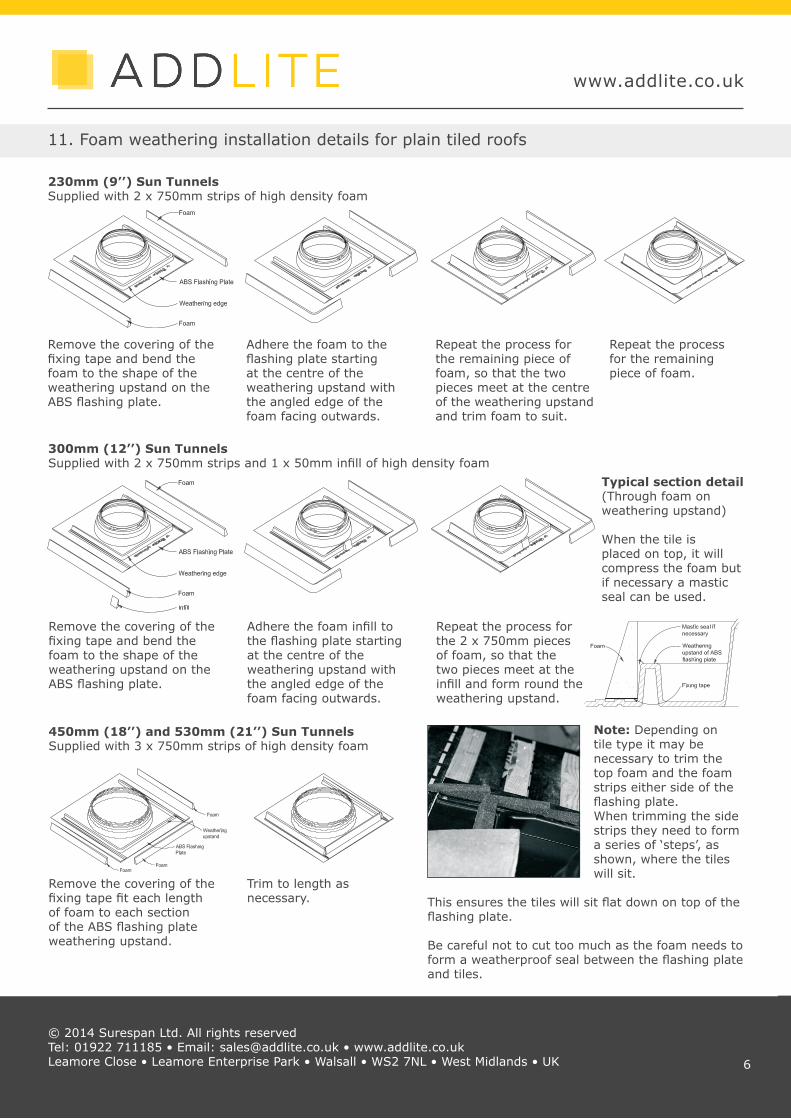
230mm (9’’) Sun TunnelsSupplied with 2 x 750mm strips of high density foam
11. Foam weathering installation details for plain tiled roofs
© 2014 Surespan Ltd. All rights reserved Tel: 01922 711185 • Email: [email protected] • www.addlite.co.ukLeamore Close • Leamore Enterprise Park • Walsall • WS2 7NL • West Midlands • UK
Remove the covering of the fixing tape and bend the foam to the shape of the weathering upstand on the ABS flashing plate.
Adhere the foam to the flashing plate starting at the centre of the weathering upstand with the angled edge of the foam facing outwards.
Repeat the process for the remaining piece of foam, so that the two pieces meet at the centre of the weathering upstand and trim foam to suit.
Repeat the process for the remaining piece of foam.
300mm (12’’) Sun TunnelsSupplied with 2 x 750mm strips and 1 x 50mm infill of high density foam
Remove the covering of the fixing tape and bend the foam to the shape of the weathering upstand on the ABS flashing plate.
Adhere the foam infill to the flashing plate starting at the centre of the weathering upstand with the angled edge of the foam facing outwards.
Repeat the process for the 2 x 750mm pieces of foam, so that the two pieces meet at the infill and form round the weathering upstand.
450mm (18’’) and 530mm (21’’) Sun TunnelsSupplied with 3 x 750mm strips of high density foam
Remove the covering of the fixing tape fit each length of foam to each section of the ABS flashing plate weathering upstand.
Trim to length as necessary.
Note: Depending on tile type it may be necessary to trim the top foam and the foam strips either side of the flashing plate. When trimming the side strips they need to form a series of ‘steps’, as shown, where the tiles will sit.
This ensures the tiles will sit flat down on top of the flashing plate.
Be careful not to cut too much as the foam needs to form a weatherproof seal between the flashing plate and tiles.
Typical section detail(Through foam on weathering upstand)
When the tile is placed on top, it will compress the foam but if necessary a mastic seal can be used.
6

www.addlite.co.uk
For bold rolled or profiled tiled roofs a Code 4 lead flashing can be supplied. It is supplied with the sides rolled and an ABS support ring for transportation Unroll the sided and remove the ring prior to installation. It is important not to damage the lead, since any blemishes are very difficult to remove.
Position the lead flashing on the roof at the desired position then remove the row of tiles above the top of the lead flashing. Dress about 25mm over the top of the next row of tiles, as shown. This helps to stop the lead flashing from sliding.
Dress over the row of tiles at the top edge of the lead and over the row of tiles at the bottom of the lead, replace tiles removed.
12. Fitting a lead flashing on bold rolled tiles
© 2014 Surespan Ltd. All rights reserved Tel: 01922 711185 • Email: [email protected] • www.addlite.co.ukLeamore Close • Leamore Enterprise Park • Walsall • WS2 7NL • West Midlands • UK
Place the collar carefully over the top of the lead making sure to align one of the lugs on the collar pointing towards the ridge of the roof (as shown) then push down the collar so that it fits firmly on top of the lead.
Drill five equi-spaced holes around the lowest part of the collar, then secure the collar to the lead flashing with closed pop-rivets (supplied). If you need to seal any of the lead, make sure you only use the lead sealant provided.
13. Fitting the collar
ridge lug
fixing holes for closed pop rivets
14. Assembling the pipe
Lie the pipe on its side with the seam facing upwards. It is important that the protective film should be left on the inside surface of the pipe until later. This protects the pipe from dirty finger marks and also stops dust or dirt getting on the surface of the pipe. Align the ends of the pipe. The special seams clip into one another forming a locking action. Put pressure on the seam all along its length to ensure the seal is secure. Carefully apply a length of aluminium tape over the made joint, as it is extremely difficult to remove the tape once applied. Carefully run a Stanley knife down both sides of the joint at points ‘A’ as shown, where the protective film is attached to the inside of the pipe so as to be able to release the film later without too much difficulty.
Care must be taken when handling the Sun Tunnel, as the edges may be sharp.!
seam
seam lock
tape over joint
‘A’
‘A’
7

www.addlite.co.uk
15. Assembly of 450mm and 530mm elbows
© 2014 Surespan Ltd. All rights reserved Tel: 01922 711185 • Email: [email protected] • www.addlite.co.ukLeamore Close • Leamore Enterprise Park • Walsall • WS2 7NL • West Midlands • UK 8
16. Fitting the first pipe
30° Adjustable Elbows
1. Pop rivet Section 1 together at c and d2. Pop rivet Section 2 at b 3. Insert Section 1 into Section 2 4. Pop rivet Section 2 at a
1 2
c d a b
Joint
Joint Joint
12 3
a cbd e g f
1 2
c d a b
Joint
Joint Joint
12 3
a cbd e g f
45° Adjustable Elbows
1. Pop rivet Section 1 together at a, b and c 2. Pop rivet Section 2 at d3. Insert Section 1 into Section 2 4. Pop rivet Section 2 at e 5. Pop rivet Section 3 at f 6. Insert Section 1 into Section 3 7. Pop rivet section 3 at g
Note: It is recommended that you peel back the protective lining just sufficient to assemble the elbow but leave the protective film in place to be removed after the fitting of the elbows, to avoid the possibility of fingermarks or damage to the completed elbows.
From the loft space push the first pipe (crimped end should be facing into the loft) through ABS undercloak and out through the flashing plate or collar by about 50mm.
Push in the elbow section, adjusting it by rotating the sections to achieve the correct angle so the crimped end of the elbow points vertically down. Push the second pipe into the elbow opening and check it aligns to the ceiling opening position. If necessary, adjust the first pipe by sliding in or out of the flashing or collar to achieve this.
Once satisfied, remove the elbow and second pipe taking care not to move the first pipe, then return to the roof. Carefully apply the brushed nylon gasket to the top of the collar (as shown). The gasket should be level with the top of the ABS flashing or collar. This gasket seals the Sun Tunnel against ingress of dirt or insects but still allows the Sun Tunnel to ‘breathe’, thereby preventing any later problems of condensation.
Secure the pipe in position using four of the 15mm self tapping screws and washers supplied, screwing through the brushed nylon gasket and into the rigid Sun Tunnel.
Trim the top of the pipe with tin snips (if necessary) to leave at least 5mm of pipe protruding through the flashing or collar. Once the pipe is fixed in position, carefully wipe the top of the outer surface of the Sun Tunnel to remove any moisture, dirt or finger marks, etc. and apply a thick bead of silicone sealant, to the gap between the Sun Tunnel and the ABS collar, and then allow to dry.
Ensure the first pipe is the crimped end connecting piece. !
Applying the silicone sealant is the most important part of the Sun Tunnel installation since this will prevent any rain or condensation from running down the outside of the Sun Tunnel which may create a water stain on the ceiling.
!
brushed nylon gasket
silicone sealing bead
5mm position of 15mm screws
www.addlite.co.uk
17. Fitting the dome
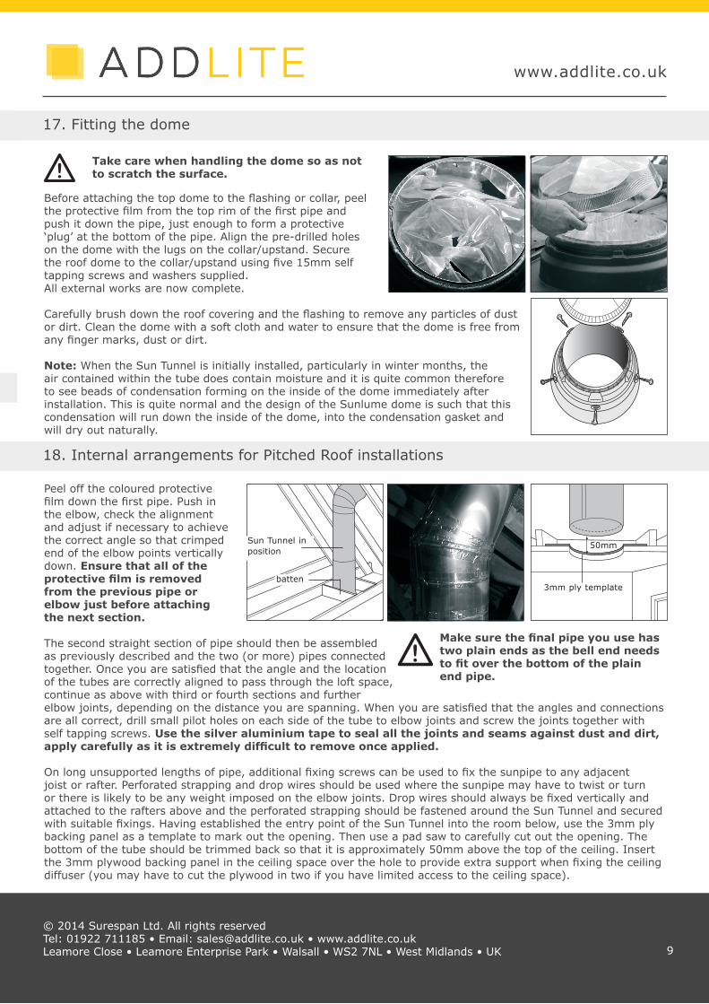
Peel off the coloured protective film down the first pipe. Push in the elbow, check the alignment and adjust if necessary to achieve the correct angle so that crimped end of the elbow points vertically down. Ensure that all of the protective film is removed from the previous pipe or elbow just before attaching the next section.
The second straight section of pipe should then be assembled as previously described and the two (or more) pipes connected together. Once you are satisfied that the angle and the location of the tubes are correctly aligned to pass through the loft space, continue as above with third or fourth sections and further elbow joints, depending on the distance you are spanning. When you are satisfied that the angles and connections are all correct, drill small pilot holes on each side of the tube to elbow joints and screw the joints together with self tapping screws. Use the silver aluminium tape to seal all the joints and seams against dust and dirt, apply carefully as it is extremely difficult to remove once applied.
On long unsupported lengths of pipe, additional fixing screws can be used to fix the sunpipe to any adjacent joist or rafter. Perforated strapping and drop wires should be used where the sunpipe may have to twist or turn or there is likely to be any weight imposed on the elbow joints. Drop wires should always be fixed vertically and attached to the rafters above and the perforated strapping should be fastened around the Sun Tunnel and secured with suitable fixings. Having established the entry point of the Sun Tunnel into the room below, use the 3mm ply backing panel as a template to mark out the opening. Then use a pad saw to carefully cut out the opening. The bottom of the tube should be trimmed back so that it is approximately 50mm above the top of the ceiling. Insert the 3mm plywood backing panel in the ceiling space over the hole to provide extra support when fixing the ceiling diffuser (you may have to cut the plywood in two if you have limited access to the ceiling space).
© 2014 Surespan Ltd. All rights reserved Tel: 01922 711185 • Email: [email protected] • www.addlite.co.ukLeamore Close • Leamore Enterprise Park • Walsall • WS2 7NL • West Midlands • UK
18. Internal arrangements for Pitched Roof installations
Before attaching the top dome to the flashing or collar, peel the protective film from the top rim of the first pipe and push it down the pipe, just enough to form a protective ‘plug’ at the bottom of the pipe. Align the pre-drilled holes on the dome with the lugs on the collar/upstand. Secure the roof dome to the collar/upstand using five 15mm self tapping screws and washers supplied. All external works are now complete.
Carefully brush down the roof covering and the flashing to remove any particles of dust or dirt. Clean the dome with a soft cloth and water to ensure that the dome is free from any finger marks, dust or dirt.
Note: When the Sun Tunnel is initially installed, particularly in winter months, the air contained within the tube does contain moisture and it is quite common therefore to see beads of condensation forming on the inside of the dome immediately after installation. This is quite normal and the design of the Sunlume dome is such that this condensation will run down the inside of the dome, into the condensation gasket and will dry out naturally.
�
Take care when handling the dome so as not to scratch the surface.!
Make sure the final pipe you use has two plain ends as the bell end needs to fit over the bottom of the plain end pipe.
!
Sun Tunnel in position
batten3mm ply template
50mm
9

www.addlite.co.uk
© 2014 Surespan Ltd. All rights reserved Tel: 01922 711185 • Email: [email protected] • www.addlite.co.ukLeamore Close • Leamore Enterprise Park • Walsall • WS2 7NL • West Midlands • UK
The efficiency of the unit is such that even in dull light, eye damage could result.
Screw the fixing ring through ceiling and into the plywood backing template using five of the 45mm screws supplied. Remove the protective film from the assembled bell end length. Pass the bell end length through the fixing ring and slide over the trimmed plain end pipe.
Remove any remainder of the protective lining.
The ceiling diffuser is designed to push fit into the bottom of the bell end pipe. Twist the little turn buttons, which securely hold the diffuser in place. You can then clip the diffuser trim into place, making sure the lugs on the inside of the trim do not align with any of the screw position cut-outs on the fixing ring.
If the ceiling is not perfectly flat, such as an Artex ceiling or similar, apply a thin bead of a proprietary sealant around the external edge of the white trim to seal any gap between the ceiling trim and the ceiling itself. Lugs must not align with central ring diffuser clips. If it is ever necessary to remove the ceiling trim at a later date, clean off the proprietary filler and remake the joint.
Return to the loft space and carefully seal all joints and seams of the bell end length.
Dust may enter the Sun Tunnel during installation, which may settle on the ceiling diffuser over a period of time. Simply remove the trim and diffuser and clean with a dry lint-free cloth, then replace and reseal if necessary. No further cleaning or long term maintenance should be required but if flies for insects appear in the diffuser, these should be removed. Some insects are attracted by strong light so carefully check to ensure that silver tape covers every possible gap.
11. Fitting the ceiling diffuser
To avoid any possibility of eye damage, be careful not to look upwards through the Sun Tunnel.
!
10