
Piping Pacage - Price Industries
15
v001 – Issue Date: 02/19/21 © 2021 Price Industries Limited. All rights reserved. MANUAL – INSTALLATION + SYSTEM COMPONENTS Piping Package
Transcript of Piping Pacage - Price Industries

v001 – Issue Date: 02/19/21© 2021 Price Industries Limited. All rights reserved.
MANUAL – INSTALLATION + SYSTEM COMPONENTS
Piping Package

priceindustries.com | PIPING PACKAGE - Manual
PIPING PACKAGETABLE OF CONTENTS
General Overview
Introduction ..................................................................1
Receiving/Inspection
Before You Start ...........................................................2
Safety Precautions ........................................................2
Inspection .....................................................................2
Installation ....................................................................2
System Components Functionality/Maintenance
Temperature Control Valve ............................................3
Automatic Balancing Valve ............................................3
Manual Balancing Valve ................................................4
Y-Strainer ......................................................................5
Union ............................................................................5
Flex Hose .....................................................................6
System Component Specifications
Automatic Balancing Valve ............................................8
Manual Balancing Valve ................................................8
Y-Strainer ......................................................................9
Union ............................................................................9
Balancing Valve ..........................................................10
Flex Hose ...................................................................10
Replacement Components
Replacement Components .........................................11

1priceindustries.com | PIPING PACKAGE - Manual
PIPING PACKAGEGENERAL OVERVIEW
IntroductionWater to air heat exchangers are a common reheat accessory used within the terminal and fan coil industry. With this, comes the requirement of a piping package to strain the fluid, regulate fluid flow and pressure, discharge air, and commission or drain the coil.
The utilization of a Price factory mounted piping package in combination with a Price water coil can reduce the time and cost in comparison to the traditional field installation. In addition to this each factory-mounted piping package will undergo pressure decay and sniff testing to assure leakage free assemblies.
FIGURE 1: 2-WAY PIPING PACKAGE
priceindustries.com | PIPING PACKAGE - Manual2 priceindustries.com | PIPING PACKAGE - ManualPIPING PACKAGE - Manual | priceindustries.com
PIPING PACKAGERECEIVING/INSPECTION
Before You StartSafety Precautions
Read all the instructions before you handle, install, or do any maintenance work on any of the piping package components. Only trained persons who have knowledge of the product and safety precautions should carry out work on the piping package. Proper eye protection should be worn when working on different pressure containing parts. Be aware of live electrical components on the piping package during installation and maintenance. Only users trained with these live components should handle any work required.
More information surrounding the water coil itself is in its respective installation manual.
Use the piping package only in the manner intended by the manufacturer. If you have any questions, contact:
Piping Package Support Canada, United States, International Export
Ph: 204-654-5613 ext. 2 Email: [email protected]
Inspection
All factory mounted piping packages are inspected before shipment. If damage is found, report it immediately to the delivery carrier. This includes valves, strainers, controllers, piping, and any other piping package accessories.
Filter Information
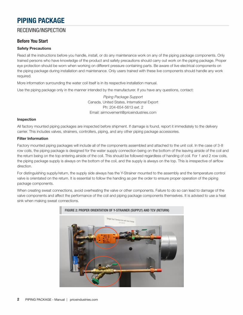
Factory mounted piping packages will include all of the components assembled and attached to the unit coil. In the case of 3-8 row coils, the piping package is designed for the water supply connection being on the bottom of the leaving airside of the coil and the return being on the top entering airside of the coil. This should be followed regardless of handing of coil. For 1 and 2 row coils, the piping package supply is always on the bottom of the coil, and the supply is always on the top. This is irrespective of airflow direction.
For distinguishing supply/return, the supply side always has the Y-Strainer mounted to the assembly and the temperature control valve is orientated on the return. It is essential to follow the handing as per the order to ensure proper operation of the piping package components.
When creating sweat connections, avoid overheating the valve or other components. Failure to do so can lead to damage of the valve components and affect the performance of the coil and piping package components themselves. It is advised to use a heat sink when making sweat connections.
FIGURE 2: PROPER ORIENTATION OF Y-STRAINER (SUPPLY) AND TCV (RETURN)

3priceindustries.com | PIPING PACKAGE - Manual
PIPING PACKAGESYSTEM COMPONENTS FUNCTIONALITY/MAINTENANCE
priceindustries.com | PIPING PACKAGE - Manual
System Components Functionality/MaintenanceTemperature Control Valve
Temperature Control Valves are available by Price or by others for factory installation. They are available for 2-way and 3-way configurations in which the 3-way valve is piped in a mixing configuration. They are available in 24V and 110-230VAC electrical voltages, On/Off, floating, and proportional control.
If the TCV has been provided by others for either factory mounting or field mounting, the technician should reach out to the local Price Industries Sales Rep for any additional material on the provided component.
If Price Industries have provided the TCV, reach out to the local Price Industries Sales Representative or Air Movement Team for more information.
Automatic Balancing Valve
The automatic balancing valves provided will be a combination of the pressure independent automatic control valve itself, an isolation ball valve, union end, and have the option of PT port and handle extension accessories.
During start-up, ensure to eliminate air in the fluid to achieve maximum performance from the balancing valve.
PT test plug locations can be reference from Figure 4. High-pressure port referenced in red and the low-pressure port referenced in green.
The automatic control valve are installed in the horizontal plane and the valve position should not be adjusted to ensure proper operation.
FIGURE 3: 2-WAY AND 3-WAY TEMPERATURE CONTROL VALVES
FIGURE 4: AUTOMATIC BALANCING VALVE
LO
HI

4 priceindustries.com | PIPING PACKAGE - ManualPIPING PACKAGE - Manual | priceindustries.com
PIPING PACKAGESYSTEM COMPONENTS FUNCTIONALITY/MAINTENANCE
When flushing the system prior to start up or during maintenance ensure the valve cartridge is removed. This component can be removed by hand for either replacement or before flushing the system. A breakdown of these components can be seen in Figure 5 and the cartridge can be accessed by unscrewing the chamber cap
Before removing the cartridge, shut the inlet and outlet isolation valve and drain the coil. Upon start up, slowly open the isolation valve, purge any lingering air, and check for leaks.
The manual balancing valve does not require regular maintenance under normal operating conditions but routinely visually inspected.
Manual Balancing Valve
The manual balancing valve provided by Price is a combination of a modified venture, ball valve, and union end. In addition, pressure ports and handle extensions are optional accessories.
During start-up, ensure to eliminate air in the fluid to achieve maximum performance from the balancing valve.
The manual control valves are installed in the horizontal plane and the valve position should not be adjusted to ensure proper operation.
PT test plug locations can be reference from Figure 6. High-pressure port referenced in red and the low-pressure port referenced in green.
The manual balancing valve does not require regular maintenance under normal operating conditions but routinely visually inspected.
FIGURE 5: FLOW CONTROL CARTRIDGE REMOVAL
FIGURE 6: MANUAL BALANCING VALVE

5priceindustries.com | PIPING PACKAGE - Manual
PIPING PACKAGESYSTEM COMPONENTS FUNCTIONALITY/MAINTENANCE
Y-Strainer
The Y-Strainer provided by Price is a combination of strainer, ball valve, blowdown, and union end. It is available with PT port and handle extension accessories.
This component will be installed on the supply side of the coil and should maintain its horizontally installed orientation. This is to ensure adequate drainage from the strainer when required.
Dirt build up can be removed using the integrated blowdown on the Y-Strainer. After draining, close the valve by turning the handle perpendicular to the flow. The blowdown cap is not designed to hold steady flow.
The Y-Strainer does not require regular maintenance under normal operating conditions but routinely visually inspected.
For strainer screen maintenance/replacement:
• Close inlet and outlet isolation valves and drain the coil.
• Remove chamber cap on the bottom of the strainer
• Screen can be removed by hand
• Replace screen and O-Ring on the chamber cap
• Replace chamber cap onto valve body, tightening using #13/16” wrench
• Slowly open isolation valve
• Purge air and check for leaks
• Filters should be periodically maintenance to prevent damage to the valve body
Union
Provided Union will come with interchangeable tail pieces and have optional PT port and PT extensions.
If venting is required, ensure that these accessories maintain their upward facing orientation. The union does not require regular maintenance under normal operating conditions but routinely visually inspected.
FIGURE 7: Y-STRAINER
FIGURE 8: Y-STRAINER SCREEN MAINTENANCE
FIGURE 9: UNION

6 priceindustries.com | PIPING PACKAGE - ManualPIPING PACKAGE - Manual | priceindustries.com
PIPING PACKAGESYSTEM COMPONENTS FUNCTIONALITY/MAINTENANCE
Flex Hose
Flex hose is available in 12”, 18”, and 24” length with SWT, FNPT, and MNPT connections. They are provided to ease pipefitting process in the field due to their flexible construction.
Installation Overview:
• When connecting to the hose end, do not put a torsional or torque load on the hose itself.
- When tightening the female thread nut of the hose, hold the ferrule stationary by hand while tightening the screw connections.
- When tightening male connections, hold the male fitting hexagonal shoulder provided at the base of the male connector when tightening, as the male threaded connections do no swivel. Example of this can be seen in Figure 13.
• When working with the flex hose, do no install the hose in tension. Allow for an extra 5% in actual hose length to account for shrinkage when the hose is subject to internal pressure. Example of this can be seen in Figure 14.
FIGURE 13: TIGHTENING MALE FLEX HOSE PROPERLY
FIGURE 14: ACCOUNTING FOR SHRINKAGE IN FLEX HOSE
FIGURE 12: FLEX HOSE

7priceindustries.com | PIPING PACKAGE - Manual
PIPING PACKAGESYSTEM COMPONENTS FUNCTIONALITY/MAINTENANCE
• Avoid tight bends in the flex hose as this can lead to a reduction in flow capacity, increase pressure drop, and potential operation failure. Example of this can be seen in Figure 15.
• Ensure that flex hose only bends in one plane of reference. Example: Only bending it upwards or downwards without bending it to the left or right. Failure to do this can create higher amounts of torsional load on the hose. Recommended bend dimensions can be seen in Figure 16.
When working with the flex hose:
• Avoid over tightening as this can cause damage to the gasket and sealing surfaces
• Do not compress the flexible connector to fit
• Do not stretch flexible connector to fit a gap larger than its factory furnished length
• Do not torque the end connectors
• Do not support external weight with the hose
• Anchor hose to prevent transmission of vibrations in the piping system
• Do not force hose into too much lateral offset
• Do not bend hose less than 15” radius intermittent or 3” static
FIGURE 15: PROPER BEND INSTALLATION OF FLEX HOSE
FIGURE 16: FLEX HOSE BENDING PARAMETERS
Table 1: Flex Hose bending Parameters
Size Length (in) A (in) B (in)R Min. Bend Radius (in)
C (max) Based on R
½”
12 1.6 0.9 3.5 114
18 1.6 0.9 3.5 180
24 1.6 0.9 3.5 180
¾”12 2.2 1.4 3.5 79
18 2.2 1.4 3.5 176
24 2.2 1.4 3.5 180

priceindustries.com | PIPING PACKAGE - Manual8 priceindustries.com | PIPING PACKAGE - ManualPIPING PACKAGE - Manual | priceindustries.com
PIPING PACKAGESYSTEM COMPONENTS FUNCTIONALITY/MAINTENANCE
Materials & Design Data
BodyHot forged brass ASTM B283, 600 WOG, 325°F, Interchangeable union ends
End PiecesHot forged brass ASTM, 200PSI, 200°F
Handle & Nut Zinc Plated / PVC Coated
Ball Hard Chrome Plated Brass
Ball Seals Teflon
Shaft Brass
Shaft Seals Dual FKM O-Rings
Union Seal FKM O-Ring
Cap Seal FKM O-Ring
Balancing Globe Brass
Handle Nylon, Glass-Filled
Accuracy +/- 5%
Materials & Design Data
BodyHot forged brass ASTM B283, 600 WOG, 325°F, Interchangeable union ends
End PiecesHot forged brass ASTM B283, 200PSI, 200°F
Handle & Nut Zinc Plated / PVC Coated
Memory Stop 1080 Cold Rolled Steel, Coated
Ball Hard Chrome Plated Brass
Ball Seals Teflon
Shaft Brass
Shaft Seals Dual FKM O-Rings
Union Seal FKM O-Ring
Accuracy +/- 5%
Automatic Balancing Valve:
Manual Balancing Valve:

9priceindustries.com | PIPING PACKAGE - Manual
PIPING PACKAGESYSTEM COMPONENT SPECIFICATIONS
priceindustries.com | PIPING PACKAGE - Manual
Materials & Design Data
BodyHot forged brass ASTM B283, 600 WOG, 325°F, Interchangeable union ends
End PiecesHot forged brass ASTM B283, 200PSI, 200°F
Handle & Nut Zinc Plated
Memory Stop 1080 Cold Rolled Steel, Coated
Ball Hard Chrome Plated Brass
Ball Seals Teflon
Shaft Brass
Shaft Seals Dual FKM O-Rings
Union Seal FKM O-Ring
Cap Seal FKM O-Ring
Filter Screen 304 Stainless Steel, Removable
Materials & Design Data
BodyHot forged brass ASTM B283, 600 WOG, 325°F, Interchangeable union ends
End PiecesHot forged brass ASTM B283, 200PSI, 200°F
Union Seal FKM O-Ring
Y-Strainer:
Union:

priceindustries.com | PIPING PACKAGE - Manual10 priceindustries.com | PIPING PACKAGE - ManualPIPING PACKAGE - Manual | priceindustries.com
PIPING PACKAGESYSTEM COMPONENT SPECIFICATIONS
Materials & Design Data
BodyHot forged brass ASTM B283, 600 WOG, 325°F, Interchangeable union ends
End PiecesHot forged brass ASTM B283, 200PSI, 200°F
Handle Aluminum
Ball Hard Chrome Plated Brass
Ball Seals Teflon
Shaft Brass, Blowout-Proof
Shaft Seals Dual FKM O-Rings
Union Seal FKM O-Ring
Memory Stop Stainless Steel
Hose Specs 400PSI, 248F
Hose Core Reinforced EDPM
Hose Braid Stainless Steel
Hose Fittings Brass OT58
Hose Gasket EDPM
Materials & Design Data
Core KEVLAR Reinforced EDPM
Braid Stainless Steel
Fitting Brass OT58
Ferrule Stainless Steel
Seals EPDM
Adapter Brass
ConnectorsFire rated: ASTM E 84-00, NFPA 255, ANSI/UL 723 & UBC 8-1 Intended for water use only
Fittings MNPT
Seals Gasket & O-Ring
Ball Valve:
Flex Hose:

11priceindustries.com | PIPING PACKAGE - Manual
PIPING PACKAGEREPLACEMENT COMPONENTS
priceindustries.com | PIPING PACKAGE - Manual
Replacement Componenets
For purchase of replacement parts, reach out to your local Price Industries Sales Representative.
Component Description Part #
Auto Balancing Valve
½”, 0.33GPM
026480
-001
½”, 0.50GPM -002
½”, 0.75GPM -003
½”, 1.00GPM -004
½”, 1.25GPM -005
½”, 1.50GPM -006
½”, 1.75GPM -007
½”, 2.00GPM -008
½”, 2.25GPM -009
½”, 2.50GPM -010
½”, 2.75GPM -011
½”, 3.00GPM -012
½”, 3.50GPM -013
½”, 4.00GPM -014
½”, 4.50GPM -015
½”, 5.00GPM -016
½”, 5.50GPM -017
½”, 6.00GPM -018
¾”, 6.00GPM -019
¾”, 7.00GPM -020
¾”, 8.00GPM -021
¾”, 9.00GPM -022
¾”, 10.50GPM -023
¾”, 11.00GPM -024
¾”, 12.00GPM -025
¾”, 13.00GPM -026
¾”, 14.00GPM -027
¾”, 15.00GPM -028
Manual Balancing Valve
½”, Cv 0.30
026481
-001
½”, Cv 0.66 -002
½”, Cv 1.32 -003
½”, Cv 3.53 -004
¾”, Cv 7.42 -005
¾”, Cv 16.6 -006
Y-Strainer
½”, 2 Way
041657
-002
¾”, 2 Way -003
½”, 3 Way -004
¾”, 3 Way -005
Union½” UU to ½” MNPT
041672-001
¾” UU to ¾” MNPT -002

12 priceindustries.com | PIPING PACKAGE - ManualPIPING PACKAGE - Manual | priceindustries.com
PIPING PACKAGEREPLACEMENT COMPONENTS
Component Description Part #
18” Flex Hose
½” FNPSH to FNPSH
041618
-001
¾” FNPSH to FNPSH -002
½” FNPSH to MNPT -003
¾” FNPSH to MNPT -004
Ball Valve ½” NXU to ½” MNPT
041672-001
¾” NXU to ¾” MNPT -002
Temperature Control Valve (Belimo)
ACTUATOR 1/2" 2-WAY ON/OFF
076535
-001
ACTUATOR 1/2" 2-WAY FLT -002
ACTUATOR 1/2" 2-WAY MOD CV1.2
-003
ACTUATOR 1/2" 2-WAY MOD CV2.4
-004
ACTUATOR 1/2" 2-WAY MOD CV5.9
-005
ACTUATOR 3/4" 2-WAY ON/OFF
-006
ACTUATOR 3/4" 2-WAY FLT -007
ACTUATOR 3/4" 2-WAY MOD CV2.3
-008
ACTUATOR 3/4" 2-WAY MOD CV4.6
-009
ACTUATOR 3/4" 2-WAY MOD CV9.8
-010
ACTUATOR 1/2" 3-WAY ON/OFF
-011
ACTUATOR 1/2" 3-WAY MOD CV1.2
-012
ACTUATOR 1/2" 3-WAY MOD CV4.7
-013
ACTUATOR 3/4" 3-WAY ON/OFF
-014
ACTUATOR 3/4" 3-WAY MOD CV4.7
-015
ACTUATOR 3/4" 3-WAY MOD CV7.4
-016

This document contains the most current product information as of this printing. For the most up-to-date product information, please go to priceindustries.com
© 2021 Price Industries Limited. All rights reserved.
priceindustries.com | PIPING PACKAGE - Manual