Pipelining the MIPS Datapath - GitHub Pages · Today’s lecture Pipeline implementation...
35
Pipelining the MIPS Datapath
Transcript of Pipelining the MIPS Datapath - GitHub Pages · Today’s lecture Pipeline implementation...

Pipelining the MIPS Datapath

Today’s lecture Pipeline implementation Single-cycle Datapath Pipelining performance Pipelined datapath Example

Refresher: The Full Single-cycle Datapath
wr_enable
clk
resetalu_op[2:0]
A[31:0]
B[31:0]
out[31:0]0
1 s
overflowzero
negative
alu_src2
alu_op[2:0]write_enable
alu_src2rd_src
3
inst[31:0]
inst[25:21]
inst[20:16]
inst[15:11]
inst[20:16]
rd_src
rs
rt
rd
rt
5
5
5
16
6
6
32
inst[15:0]
inst[31:26]
inst[5:0]
imm16
32
32
32
3
32
3
ADD
432
32
1
30
PC[31:0]
nextPC[31:0]
PC[31:2]
except
A_addr
B_addr
W_addr
A_data
B_data
W_en
W_data
reset
25x32 Register
File
MIPS instruction decoderalu_op[2:0]
write_enable
alu_src2rd_src
except
opcode[5:0]
funct[5:0]
A
B
out
0
1s
Instruction Memory
addr[29:0]data[31:0]
PC RegisterD[31:0]
Q[31:0]resetenable
3ADD
branch offset
32ALU
0 1 2 3
PC+4[31:28] 2'b0
ALU
control_type
inst[25:0] 26
4
32
3232
32
32
32
control_type[1:0]2
control_type[1:0]
zero
32<<2in[29:0] out[31:0]
Sign Extenderin[15:0] out[31:0]
branch offset
30'b0
10 slt
16'b0
16
lui 1 0
luiluisltslt
word_webyte_we
out[1:0]
data
_out
[31:
0]
data
_out
[31:
24]
data
_out
[23:
16]
data
_out
[15:
8]
data
_out
[7:0
]
mem_readbyte_load
32
1
0
addr[31:0]
data_out[31:0]
data_in[31:0]
word_webyte_we
Data Memory
reset
0123
1
0 24'b0
32
32
32
32
32
byte_loadbyte_loadword_weword_webyte_webyte_wemem_readmem_read

We will use a simplified implementation of MIPS to create a pipelined version
Arithmetic: add sub and or slt
Data Transfer:
lw sw
Control: beq

Sign Extend
4
ADD
PCSrc
RegWrite
rd1
0
RegDst
MIPS Decoder
0
1
ALUSrc
ALUOp
<< 2
ADD
Address
Write Data
Read Data
Data Memory
1
0
MemToReg
0
1
Read Address
Instruction[31:0]
Instruction Memory
A
B
ReadAddr1
ReadAddr2
WriteAddr
WriteData
ReadData1
ReadData2
Register File
rt
imm
rs
rt
MemReadMemWrite
PC
EN
2ns
2ns 2ns1ns
2ns 2ns
Worst-case delay from register-read to register-write determines clock speed
1ns

IF ID EX MEM WB
IF ID EX MEM WB
0ns 2 3 5 7 8 10 11 13 15 16 ns
clk
Single-cycle datapath completes one instruction per clock cycle

Add pipeline registers in between stages to increase clock speed
Approximate as one big pipeline register between each stage. The registers are named for the stages they connect.
IF/ID ID/EX EX/MEM MEM/WB
No pipeline register after the WB stage, because write is to the register file.

Paths from register-read to register-write are shorter, clock cycle shorter
Sign Extend
4
ADD
PCSrc
RegWrite
rd1
0
RegDst
MIPS Decoder
0
1
ALUSrcALUOp
<< 2
ADD
Address
Write Data
Read Data
Data Memory
1
0
MemToReg
IF/ID ID/EX
WBMEX
EX/MEM
WBM
Mem/WB
WB
0
1
Read Address
Instruction[31:0]
Instruction Memory
A
B
ReadAddr1
ReadAddr2
WriteAddr
WriteData
ReadData1
ReadData2
Register File
rt
imm
rd
rt
rs
rt
MemReadMemWrite
PC
EN

IF EX MEM WB
0ns 2 4 6 8 10 12 14 16 ns
ID
IF EX MEM WBID
IF EX MEM WBID
IF EX MEM WBID
clk
Pipeline datapath completes one stage per clock cycle

Pipelining improves throughput at the cost of increased latency

How long does it take to run 1000 instructions if the clock period is 8 ns?
Throughput: Time to run N instructions on the single-cycle datapath is N x clock period

Ideal pipeline performance is time to fill the pipeline + one cycle per instruction

For large N, this 5-stage pipeline quadruples performanceSingle-cycle throughput performance
= N instructions / N * 8 ns
Pipeline throughput performance = N instructions / N * 2 ns
Speedup =Pipeline performance
Single − cycle performance=
82
= 4

Data values required in later stages must be propagated forwardthrough the pipeline registers.
Sign Extend
RegWrite
rd1
0
RegDst
0
1
ALUSrcALUOp
Write Data
Read Data
Data Memory
1
0
MemToRegRead Address
Instruction[31:0]
Instruction Memory
BWriteAddr
WriteData
ReadData2
Register File
rt
imm
rd
rt
EN
Note – We cannot keep values like destination register in the “IF/ID register”
Sign Extend
4
ADD
PCSrc
RegWrite
rd1
0
RegDst
MIPS Decoder
0
1
ALUSrcALUOp
<< 2
ADD
Address
Write Data
Read Data
Data Memory
1
0
MemToReg
IF/ID ID/EX
WBMEX
EX/MEM
WBM
Mem/WB
WB
0
1
Read Address
Instruction[31:0]
Instruction Memory
A
B
ReadAddr1
ReadAddr2
WriteAddr
WriteData
ReadData1
ReadData2
Register File
rt
imm
rd
rt
rs
rt
MemReadMemWrite
PC
EN
zero
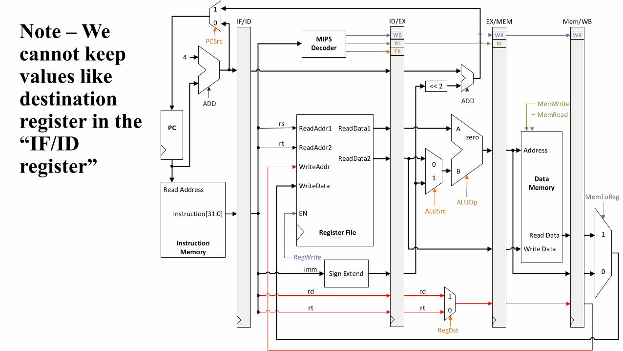
Control signals are generated in the decode stage and are propagated across stages

Categorize control signals by the pipeline stage that uses them
Stage Control signals neededEX ALUSrc ALUOp RegDst PCSrcMEM MemRead MemWriteWB RegWrite MemToReg
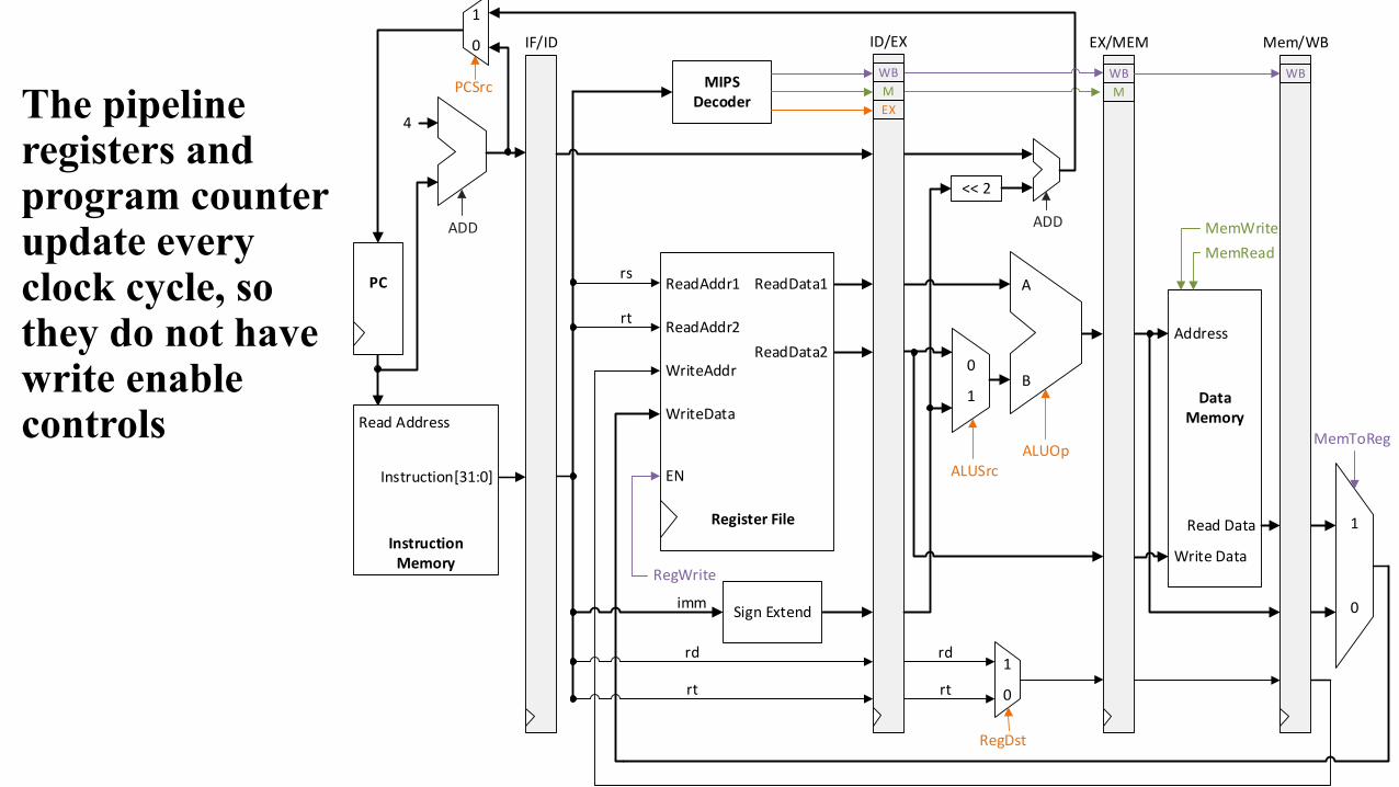
The pipeline registers and program counter update every clock cycle, so they do not have write enable controls
Sign Extend
4
ADD
PCSrc
RegWrite
rd1
0
RegDst
MIPS Decoder
0
1
ALUSrcALUOp
<< 2
ADD
Address
Write Data
Read Data
Data Memory
1
0
MemToReg
IF/ID ID/EX
WBMEX
EX/MEM
WBM
Mem/WB
WB
0
1
Read Address
Instruction[31:0]
Instruction Memory
A
B
ReadAddr1
ReadAddr2
WriteAddr
WriteData
ReadData1
ReadData2
Register File
rt
imm
rd
rt
rs
rt
MemReadMemWrite
PC
EN

1000: lw $8, 4($29)1004: sub $2, $4, $51008: and $9, $10, $111012: or $16, $17, $181016: add $13, $14, $0
ASSUMPTIONS Each register contains its number plus 100. Example: R[8] == 108, R[29] == 129 Every data memory location contains 99. Example: M[8] == 99, M[29] == 99
CONVENTIONS X indicates values that are not important, Example: Imm16 for R-type. Question marks ??? indicate values we do not know, usually resulting from
instructions coming before and after the ones in our example.
An example execution sequence
addresses in decimal

Cycle 1 (filling)IF: lw $8, 4($29) MEM: ??? WB: ???EX: ???ID: ???
Sign Extend
ADD
RegWrite
rd1
0
RegDst
0
1
ALUSrcALUOp
ADD
Address
Write Data
Read Data
Data Memory
1
0
MemToRegRead Address
Instruction[31:0]
Instruction Memory
A
B
ReadAddr1
ReadAddr2
WriteAddr
WriteData
ReadData1
ReadData2
Register File
rt
imm
rd
rt
rs
rt
MemReadMemWrite
PC
EN
1000
??
??
???
?
? ??
?
?
??? ? ?
?
?
?
?
?

Cycle 2ID: lw $8, 4($29)IF: sub $2, $4, $5 MEM: ??? WB: ???EX: ???
Sign Extend
ADD
RegWrite
rd1
0
RegDst
0
1
ALUSrcALUOp
ADD
Address
Write Data
Read Data
Data Memory
1
0
MemToRegRead Address
Instruction[31:0]
Instruction Memory
A
B
ReadAddr1
ReadAddr2
WriteAddr
WriteData
ReadData1
ReadData2
Register File
rt
imm
rd
rt
rs
rt
MemReadMemWrite
PC
EN
1004
____
??
______
__
__?
??
?
??? ? ?
?
?
?
?
?

Cycle 3ID: sub $2, $4, $5IF: and $9, $10, $11 EX: lw $8, 4($29) MEM: ??? WB: ???
Sign Extend
ADD
RegWrite
rd1
0
RegDst
0
1
ALUSrcALUOp
ADD
Address
Write Data
Read Data
Data Memory
1
0
MemToRegRead Address
Instruction[31:0]
Instruction Memory
A
B
ReadAddr1
ReadAddr2
WriteAddr
WriteData
ReadData1
ReadData2
Register File
rt
imm
rd
rt
rs
rt
MemReadMemWrite
PC
EN
1008
45
??
x25
104
105 __?
__
__
__
____
__ ?
?
?
?
?
?
__
__ __
__

Cycle 4ID: and $9, $10, $11IF: or $16, $17, $18 EX: sub $2, $4, $5 MEM: lw $8, 4($29) WB: ???
Sign Extend
ADD
RegWrite
rd1
0
RegDst
0
1
ALUSrcALUOp
ADD
Address
Write Data
Read Data
Data Memory
1
0
MemToRegRead Address
Instruction[31:0]
Instruction Memory
A
B
ReadAddr1
ReadAddr2
WriteAddr
WriteData
ReadData1
ReadData2
Register File
rt
imm
rd
rt
rs
rt
MemReadMemWrite
PC
EN
1012
1011
??
x910
110
111-1
__104
105
x
25
2 __
__
?
?
?
?
105
0 SUB
1
__

Cycle 5 (full)ID: or $16, $17, $18IF: add $13, $14, $0 EX: and $9, $10, $11 MEM: sub $2, $4, $5 WB: lw $8, 4($29)
Sign Extend
ADD
RegWrite
rd1
0
RegDst
0
1
ALUSrcALUOp
ADD
Address
Write Data
Read Data
Data Memory
1
0
MemToRegRead Address
Instruction[31:0]
Instruction Memory
A
B
ReadAddr1
ReadAddr2
WriteAddr
WriteData
ReadData1
ReadData2
Register File
rt
imm
rd
rt
rs
rt
MemReadMemWrite
PC
EN
1016
1718
____
x1618
117
118110
-1110
111
x
911
9 2
x
__
__
__
__
111
0 AND
1
105__
__

Sign Extend
ADD
RegWrite
rd1
0
RegDst
0
1
ALUSrcALUOp
ADD
Address
Write Data
Read Data
Data Memory
1
0
MemToRegRead Address
Instruction[31:0]
Instruction Memory
A
B
ReadAddr1
ReadAddr2
WriteAddr
WriteData
ReadData1
ReadData2
Register File
rt
imm
rd
rt
rs
rt
MemReadMemWrite
PC
EN
ID: add $13, $14, $0IF: ??? EX: or $16, $17, $18 MEM: and $9, $10, $11 WB: sub $2, $4, $5
Cycle 6 (emptying)
00
x x
117
111
00
x

Cycle 7ID: ???IF: ??? EX: add $13, $14, $0 MEM: or $16, $17, $18 WB: and $9, $10,
$11
Sign Extend
ADD
RegWrite
rd1
0
RegDst
0
1
ALUSrcALUOp
ADD
Address
Write Data
Read Data
Data Memory
1
0
MemToRegRead Address
Instruction[31:0]
Instruction Memory
A
B
ReadAddr1
ReadAddr2
WriteAddr
WriteData
ReadData1
ReadData2
Register File
rt
imm
rd
rt
rs
rt
MemReadMemWrite
PC
EN

Cycle 8IF: ??? EX: ??? MEM: add $13, $14, $0 WB: or $16, $17,
$18
Sign Extend
ADD
RegWrite
rd1
0
RegDst
0
1
ALUSrcALUOp
ADD
Address
Write Data
Read Data
Data Memory
1
0
MemToRegRead Address
Instruction[31:0]
Instruction Memory
A
B
ReadAddr1
ReadAddr2
WriteAddr
WriteData
ReadData1
ReadData2
Register File
rt
imm
rd
rt
rs
rt
MemReadMemWrite
PC
EN
ID: ???

Cycle 9MEM: ??? WB: add $13, $14, $0IF: ??? EX: ???ID: ???
Sign Extend
ADD
RegWrite
rd1
0
RegDst
0
1
ALUSrcALUOp
ADD
Address
Write Data
Read Data
Data Memory
1
0
MemToRegRead Address
Instruction[31:0]
Instruction Memory
A
B
ReadAddr1
ReadAddr2
WriteAddr
WriteData
ReadData1
ReadData2
Register File
rt
imm
rd
rt
rs
rt
MemReadMemWrite
PC
EN

Things to notice from the last nine slides
Instruction executions overlap Each functional unit is used by a different instruction in each cycle. In clock cycle 5, all of the hardware units are used (the pipeline is full).
This is the ideal situation, and what makes pipelined processors so fast Similar example in the book available at the end of Section 6.3.
Clock cycle1 2 3 4 5 6 7 8 9
add $sp, $sp, -4 IF ID EX NOP WBsub $v0, $a0, $a1 IF ID EX NOP WBlw $t0, 4($sp) IF ID EX MEM WBor $s0, $s1, $s2 IF ID EX NOP WBlw $t1, 8($sp) IF ID EX MEM WB

MIPs ISA makes pipelining “easy” Instruction formats are the same length and uniform Addressing modes are simple Each instruction takes only one cycle

Everything goes left to right, except …
Next time: We will discuss Data Hazards
Sign Extend
4
ADD
PCSrc
RegWrite
rd1
0
RegDst
MIPS Decoder
0
1
ALUSrcALUOp
<< 2
ADD
Address
Write Data
Read Data
Data Memory
1
0
MemToReg
IF/ID ID/EX
WBMEX
EX/MEM
WBM
Mem/WB
WB
0
1
Read Address
Instruction[31:0]
Instruction Memory
A
B
ReadAddr1
ReadAddr2
WriteAddr
WriteData
ReadData1
ReadData2
Register File
rt
imm
rd
rt
rs
rt
MemReadMemWrite
PC
EN
zero

Some instructions do not require all five stages, can we skip stages?
Clock cycle1 2 3 4 5 6 7 8 9
add$sp, $sp, -4 IF ID EX WBsub $v0, $a0, $a1 IF ID EX WBlw $t0, 4($sp) IF ID EX MEM WBor $s0, $s1, $s2 IF ID EX WBlw $t1, 8($sp) IF ID EX MEM WB

Trying to use the single stage for multiple instructions creates a structural hazard Each functional unit can only be used once per instruction
Clock cycle1 2 3 4 5 6 7 8 9
add$sp, $sp, -4 IF ID EX WBsub $v0, $a0, $a1 IF ID EX WBlw $t0, 4($sp) IF ID EX MEM WBor $s0, $s1, $s2 IF ID EX WBlw $t1, 8($sp) IF ID EX MEM WB

Insert NOP (No OPeration) stages to avoid structural hazards
Stores and Branches have NOP stages, too…
Clock cycle1 2 3 4 5 6 7 8 9
add $sp, $sp, -4 IF ID EX NOP WBsub $v0, $a0, $a1 IF ID EX NOP WBlw $t0, 4($sp) IF ID EX MEM WBor $s0, $s1, $s2 IF ID EX NOP WBlw $t1, 8($sp) IF ID EX MEM WB
R-type IF ID EX NOP WB
store IF ID EX MEM NOPbranch IF ID EX NOP NOP