Pipelining Cache
17
Pipelining Cache By Riman Mandal
-
Upload
ranaghat-college -
Category
Documents
-
view
174 -
download
0
Transcript of Pipelining Cache

Pipelining CacheBy Riman Mandal

Contents
▪ What is Pipelining?▪ Cache optimization▪ Why Pipelining cache?▪ Cache Hit and Cache Access▪ How can we implement pipelining to cache▪ Cache Pipelining effects▪ References

What is Pipelining?
Time
Jobs 24 hrs
24 hrs
24 hrs
Un-pipelined
Throughput
Parallelism
1 car / 24 hrs
1
Start and Finish a job before moving to next job

What is Pipelining? (cont.)
Time
Jobs
Throughput
Parallelism
1 car / 8 hrs
3
Pipelined Break the job into small stages
Engine1
Engine2
Engine3
Engine4
Body1
Body2
Body2
Body4
Paint1
Paint2
Paint3
Paint4
8 hr
8 hr
8 hr
x3

What is Pipelining? (cont.)
Time
Jobs 3 ns
3 ns
3 ns
Un-pipelined
Start and Finish an instruction execution before moving to next instruction
FET
DEC EXE
FET
DEC EXE
FET
DEC EXE
Cyc 1
Cyc 2
Cyc 3

What is Pipelining? (cont.)
Time
Jobs
Pipelined Break the instruction exeution into small stages
FET IR1
FET IR2
FET IR3
FET IR4
DEC IR1
DEC IR2
DEC IR3
DEC IR4
EXC IR1
EXC IR2
EXC IR3
EXC IR4
Cyc 1 Cyc
2Cyc 3 1
ns1 ns
1 ns
Un-pipelinedClock Speed =
1 / 3ns = 333 MHzPipelinedClock Speed = 1 / 1ns = 1 GHz

Cache optimization
▪ Average memory access time(AMAT) = Hit time + Miss rate × Miss penalty
▪ 5 matrices : hit time, miss rate, miss penalty, bandwidth, power consumption
▪ Optimizing Cache Access Time – Reducing the hit time (1st level catch, way-prediction)– Increasing cache bandwidth (pipelining cache, non-blocking
cache, multibanked cache)– Reducing the miss penalty (critical word first, merging write
buffers)– Reducing the miss rate (compiler optimizations)– Reducing the miss penalty or miss rate via parallelism
(prefetching)
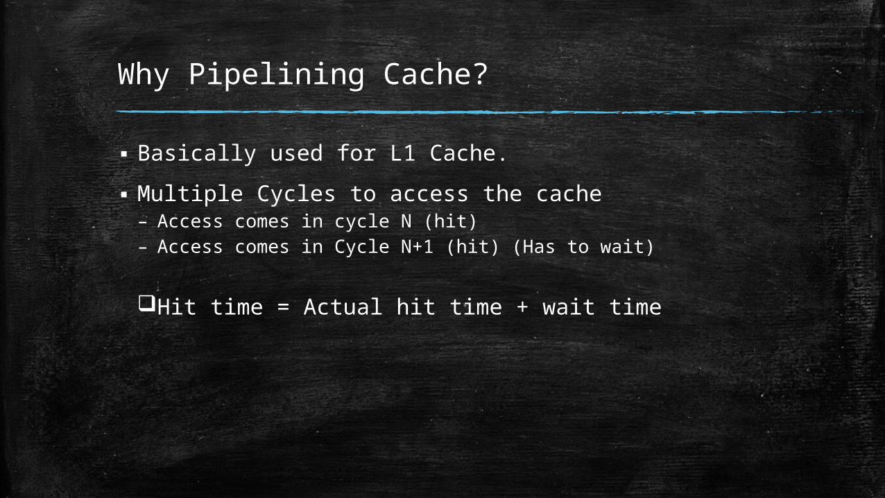
Why Pipelining Cache?
▪ Basically used for L1 Cache.▪ Multiple Cycles to access the cache– Access comes in cycle N (hit)– Access comes in Cycle N+1 (hit) (Has to wait)
Hit time = Actual hit time + wait time
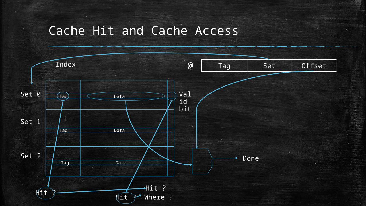
Cache Hit and Cache Access
Tag Set Offset@
Tag Data
Tag Data
Tag Data
Set 0
Set 1
Set 2
Hit ? Hit ?Hit ?
Where ?
Index
Done
Valid bit

Designing a 3 Stage pipeline Cache
▪ Reading the tag and validity bit.▪ Combine the result and find out the actual hit and start
data read.▪ Finishing the data read and transfer data to CPU.
Retrieve tag and valid bit Is Hit? Start data read Serve CPU request

Stage 1:Read tag and valid bit
Tag Set Offset@
Tag Data
Tag Data
Tag Data
Set 0
Set 1
Set 2
Hit ? Hit ?Hit ?
Where ?
Index
Done
Valid bit

Stage 2: If Hit start reading
Tag Set Offset@
Tag Data
Tag Data
Tag Data
Set 0
Set 1
Set 2
Hit ? Hit ?Hit ?
Where ?
Index
Done
Valid bit
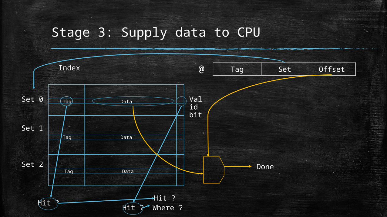
Stage 3: Supply data to CPU
Tag Set Offset@
Tag Data
Tag Data
Tag Data
Set 0
Set 1
Set 2
Hit ? Hit ?Hit ?
Where ?
Index
Done
Valid bit

Designing a 2 Stage pipeline Cache
▪ Checking the tag and validity bit and combine them to find actual hit, and find the location of data.
▪ Read data and serve the CPU request.
Retrieve tag and valid bit. Is Hit? Serve CPU request

Example
▪ Instruction-cache pipeline stages:– Pentium: 1 stage– Pentium Pro through Pentium III: 2 stages– Pentium 4: 4 stages

Pipeline Cache Efficiency
▪ Increases the bandwidth▪ increasing the number of pipeline stages leading to – greater penalty on mispredicted branches – more clock cycles between issuing the load and using the data
Technique
Hittime Bandwidth
Misspenalty
Missrate
Powerconsumptio
nPipelining
Cache _ +

References
▪ https://www.udacity.com/course/high-performance-computer-architecture--ud007
▪ https://www.youtube.com/watch?v=r9AxfQB_qlc▪ “Computer Architecture: A Quantitative Approach Fifth
Edition”, by Hennessy & Patterson