Pipeline, Liquefied Natural Gas and Breakout Tank Farm ... · 4.3.1 Pipeline Drafting Requirements...
62
National Pipeline Mapping System Standards for Pipeline, Liquefied Natural Gas and Breakout Tank Farm Operator Submissions October 2004 Office of Pipeline Safety www.npms.rspa.dot.gov Research and Special Programs Administration
Transcript of Pipeline, Liquefied Natural Gas and Breakout Tank Farm ... · 4.3.1 Pipeline Drafting Requirements...

National Pipeline Mapping System
Standards for
Pipeline, Liquefied Natural Gas and
Breakout Tank Farm Operator SubmissionsOctober 2004
Office of Pipeline Safetywww.npms.rspa.dot.gov
Research and Special Programs Administration

Standards for Pipelines, Liquefied Natural Gas, and Breakout Tank Farms
Standards for Pipeline, LNG, and Breakout Tank Farm Operator Submissions 1 U.S. DOT – 2004
Revisions to the Standards in October 2004
1. National Repository Contacts and Internet Addresses on page 6 were updated. 2. Section 1.4.2 was expanded to introduce the Internet Submission Update Tool. 3. Sections 3 and 6 were updated to reflect changes in the Attribute and Metadata Submission Tools.
Standards for Pipelines, Liquefied Natural Gas, and Breakout Tank Farms
Standards for Pipeline, LNG, and Breakout Tank Farm Operator Submissions 2 U.S. DOT – 2004
Table of Contents List of Acronyms ............................................................................................................................................................................. 4 Preface ............................................................................................................................................................................................... 5 OPS Contacts .................................................................................................................................................................................... 5 National Repository Contacts........................................................................................................................................................ 6 Internet Addresses ........................................................................................................................................................................... 6 1. Introduction.............................................................................................................................................................................. 7
1.1 Regulatory Requirements ............................................................................................................................................. 7 1.2 Development of NPMS and Standards for Data Submission................................................................................. 8 1.3 NPMS Structure ............................................................................................................................................................. 8 1.4 Data Format, Verification, and Updates..................................................................................................................... 8
1.4.1 Data Format............................................................................................................................................................ 8 1.4.2 Annual Resubmission and the Internet Submission Update Tool................................................................. 9 1.4.3 Public Contact Information ................................................................................................................................. 9
1.5 Distribution of NPMS Data........................................................................................................................................ 10 1.6 About these Standards................................................................................................................................................. 10
2. General Requirements (Key Terms and Definitions)..................................................................................................... 11 2.1 NPMS File Naming Conventions.............................................................................................................................. 14 2.2 Types of NPMS Submissions.................................................................................................................................... 14
3. Attribute Data........................................................................................................................................................................ 16 3.1 Required and Optional Attributes.............................................................................................................................. 16 3.2 Rules for Attribute Data Input ................................................................................................................................... 16 3.3 Building the Attribute Data File ................................................................................................................................ 19 3.4 Using The NPMS Attribute Data Template............................................................................................................. 20
3.4.1 System Requirements ......................................................................................................................................... 20 3.4.2 Installation Instructions...................................................................................................................................... 20 3.4.3 Step-by-Step User Instructions......................................................................................................................... 20
4. Geospatial Data (Digital or Hard-Copy Maps)................................................................................................................ 25 4.1 General Requirements for Digital Geospatial Data................................................................................................ 25 4.2 Digital Submission Techniques ................................................................................................................................. 26
4.2.1 ESRI ArcInfo Format Data Submissions........................................................................................................ 26 4.2.2 ESRI ArcView Format Data Submissions...................................................................................................... 26 4.2.3 Intergraph Corporation’s FRAMME Data Submissions .............................................................................. 26 4.2.4 Intergraph / Bentley Corporation’s Microstation and non-FRAMME Data Submissions..................... 27 4.2.5 MapInfo Data Submissions............................................................................................................................... 28 4.2.6 AutoCAD Data Submissions............................................................................................................................. 28 4.2.7 Smallworld Data Submissions.......................................................................................................................... 28 4.2.8 Generic (ASCII) Digital Data Submissions.................................................................................................... 29
4.3 Hard-Copy Submissions............................................................................................................................................. 31 4.3.1 Pipeline Drafting Requirements ....................................................................................................................... 31 4.3.2 LNG Facility Drafting Requirements .............................................................................................................. 31 4.3.3 Annotating Pipeline and LNG Attribute Data................................................................................................ 31 4.3.4 Requirements for Hard-Copy Mapping........................................................................................................... 32
5. Contact Information ............................................................................................................................................................. 34 6. Metadata................................................................................................................................................................................. 36
6.2 NPMS Metadata Template ......................................................................................................................................... 36 6.3 Using the NPMS Metadata Template ....................................................................................................................... 36
6.3.1 System Requirements ......................................................................................................................................... 37 6.3.2 Installation Instructions...................................................................................................................................... 37

Standards for Pipelines, Liquefied Natural Gas, and Breakout Tank Farms
Standards for Pipeline, LNG, and Breakout Tank Farm Operator Submissions 3 U.S. DOT – 2004
6.3.3 Metadata Entry .................................................................................................................................................... 37 6.3.4 Metadata Samples ............................................................................................................................................... 37
7. Voluntary Breakout Tank Submissions............................................................................................................................ 38 8. Submitting the Data.............................................................................................................................................................. 43
8.1 Operator Submission Checklist ................................................................................................................................. 43 8.1.1 Attribute Data Submissions............................................................................................................................... 43 8.1.2 Hard-Copy Geospatial Data Submissions....................................................................................................... 43 8.1.3 Digital Geospatial Data Submissions.............................................................................................................. 43 8.1.4. Operator Contact Information Submissions................................................................................................... 43 8.1.5 Metadata Submissions........................................................................................................................................ 43
8.2 Packaging and Sending Data...................................................................................................................................... 44 Appendix 1: Sample Hard-Copy Map and Attribute Data.........................................................................................A-1 Appendix 2: Metadata Example for Geospatial Data Submissions...........................................................................A-3 Appendix 3: Glossary...............................................................................................................................................A-11

Standards for Pipelines, Liquefied Natural Gas, and Breakout Tank Farms
Standards for Pipeline, LNG, and Breakout Tank Farm Operator Submissions 4 U.S. DOT – 2004
List of Acronyms AA.........................Anhydrous Ammonia AGA ......................American Gas Association API.........................American Petroleum Institute ASCII....................American Standard Code for Information Interchange BTS........................Bureau of Transportation Statistics, U.S. Department of Transportation CAD ......................Computer-Aided Drafting
CADD...................Computer-Aided Drafting and Design CO2 ........................Carbon Dioxide CRD.......................Crude Oil DLG.......................Digital Line Graph DOE.......................Department of Energy DOS.......................Disk Operating System DRG......................Digital Raster Graphic DXF.......................Drawing Exchange Format EMT ......................Empty FERC.....................Federal Energy Regulatory Commission FGDC....................Federal Geographic Data Committee FTP site.................File Transfer Protocol site GIS.........................Geographic Information System GPS........................Global Positioning System HG.........................Hydrogen Gas
HVL.......................Highly Volatile Liquid INGAA .................Interstate Natural Gas Association of America LNG.......................Liquefied Natural Gas LPG.......................Liquefied Petroleum Gas LUT .......................Look-Up-Table MIF........................MapInfo Interchange File MQAT...................Joint Government-Industry Pipeline Mapping Quality Action Team NAD 27, 83..........North American Datum (of 1927 or 1983) NG.........................Natural Gas NGL.......................Natural Gas Liquids NPMS....................National Pipeline Mapping System OMB......................Office of Management and Budget OPS........................Office of Pipeline Safety, U.S. Department of Transportation PRD.......................Product ROW .....................Right-Of-Way
SEF ........................Standard Exchange Format SMYS ....................Specified Minimum Yield Strength USDOT .................U.S. Department of Transportation USGS ....................United States Geological Survey UTM......................Universal Transverse Mercator

Standards for Pipelines, Liquefied Natural Gas, and Breakout Tank Farms
Standards for Pipeline, LNG, and Breakout Tank Farm Operator Submissions 5 U.S. DOT – 2004
Preface This document was prepared by the second Joint Government/Industry Pipeline Mapping Quality Action Team (MQAT II). The team was sponsored by the U.S. Department of Transportation (USDOT) Office of Pipeline Safety (OPS), American Petroleum Institute (API), American Gas Association (AGA), and Interstate Natural Gas Association of America (INGAA). Representatives on the team included OPS, Bureau of Transportation Statistics (BTS), U.S. Department of Energy (USDOE), U.S. Geological Survey (USGS), Federal Energy Regulatory Commission (FERC), state representatives from California, Louisiana, New York, and Texas, and representatives from the pipeline industry. If you have questions regarding this document, please contact one of the following representatives: OPS Contacts Samuel Hall GIS Manager U.S. Department of Transportation Office of Pipeline Safety 400 7th Street SW Washington, DC 20590 202-493-0591 • fax 202-366-4566 [email protected]
For questions regarding OPS Operator ID (OPID) information, contact: Shauna Turnbull Management and Program Analyst U.S. Department of Transportation Office of Pipeline Safety 400 7th Street SW Washington, DC 20590 202-366-3731 [email protected]

Standards for Pipelines, Liquefied Natural Gas, and Breakout Tank Farms
Standards for Pipeline, LNG, and Breakout Tank Farm Operator Submissions 6 U.S. DOT – 2004
National Repository Contacts
National Repository Project Manager NPMS National Repository Michael Baker Jr., Inc. 3601 Eisenhower Avenue Alexandria, VA 22304 703-317-6205 • fax 703-960-9125 [email protected] Amy Nelson Deputy Project Manager NPMS National Repository Michael Baker Jr., Inc. 3601 Eisenhower Avenue Alexandria, VA 22304 703-317-6294 • fax 703-960-9125 [email protected]
Internet Addresses National Pipeline Mapping System – www.npms.rspa.dot.gov
Bureau of Transportation Statistics – http://www.bts.gov
Federal Energy Regulatory Commission – http://www.ferc.gov
Federal Geographic Data Committee – http://www.fgdc.gov
Office of Pipeline Safety – http://ops.dot.gov
Research and Special Programs Administration – http://www.rspa.dot.gov
U.S. Department of Energy – http://www.energy.gov
U.S. Department of Transportation – http://www.dot.gov
U.S. Geological Survey – http://www.usgs.gov
Standards for Pipelines, Liquefied Natural Gas, and Breakout Tank Farms
Standards for Pipeline, LNG, and Breakout Tank Farm Operator Submissions 7 U.S. DOT – 2004
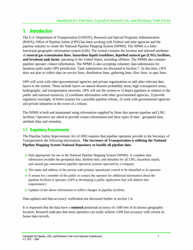
1. Introduction The U.S. Department of Transportation (USDOT), Research and Special Programs Administration (RSPA), Office of Pipeline Safety (OPS) has been working with Federal and state agencies and the pipeline industry to create the National Pipeline Mapping System (NPMS). The NPMS is a fully-functional geographic information system (GIS). The system contains the location and selected attributes of natural gas transmission lines, hazardous liquid trunklines, liquefied natural gas (LNG) facilities, and breakout tank farms operating in the United States, including offshore. The NPMS also contains pipeline operator contact information. The NPMS is also accepting voluntary data submissions for breakout tanks under OPS jurisdiction. Tank submissions are discussed in Section 7. At this time, OPS does not plan to collect data on service lines, distribution lines, gathering lines, flow lines, or spur lines. OPS will work with other governmental agencies and private organizations to add other relevant data layers to the system. These include layers on natural disaster probability areas, high consequence areas, hydrography, and transportation networks. OPS will use the system to 1) depict pipelines in relation to the public and national resources, 2) coordinate information with other governmental agencies, 3) provide regulatory oversight, 4) better prepare for a possible pipeline release, 5) work with governmental agencies and private industries in the event of a release. The NPMS is built and maintained using information supplied by firms that operate pipeline and LNG facilities. Operators are asked to provide contact information and three types of data : geospatial data, attribute data, and metadata. 1.1 Regulatory Requirements
The Pipeline Safety Improvement Act of 2002 requires that pipeline operators provide to the Secretary of Transportation the following information. The Secretary of Transportation is utilizing the National Pipeline Mapping System National Repository to handle all pipeline data.
t Data appropriate for use in the National Pipeline Mapping System (NPMS). A complete data submission includes the geospatial data, attribute data, and metadata for all LNG, hazardous liquid, and natural gas transmission pipeline operation systems operated by a company.
t The name and address of the person with primary operational control to be identified as its operator.
t A means for a member of the public to contact the operator for additional information about the pipeline facilities it operates. (OPS is developing a public application that will address this requirement.)
t Updates of the above information to reflect changes in pipeline facilities.
Data updates and data accuracy verification are discussed further in section 1.4. It is requested that the data have a minimal positional accuracy of ±500 feet of its known geographic location. Research indicates that most operators can easily achieve ±500 foot accuracy with current in-house data records.

Standards for Pipelines, Liquefied Natural Gas, and Breakout Tank Farms
Standards for Pipeline, LNG, and Breakout Tank Farm Operator Submissions 8 U.S. DOT – 2004
1.2 Development of NPMS and Standards for Data Submission A Joint Government/Industry Pipeline Mapping Quality Action Team (MQAT II) was formed to work with OPS on creating the digital pipeline location and attribute layer of the NPMS. The team was sponsored by OPS, American Petroleum Institute (API), American Gas Association (AGA), and Interstate Natural Gas Association of America (INGAA), and included representatives from multiple federal and state governmental agencies, and the natural gas and hazardous liquid pipeline industry. MQAT II drafted standards and incorporated appropriate recommendations from outside entities, including comments from mapping vendors, pipeline operators, and state agencies outside the MQAT II. The standards underwent two pilot tests. These tests helped to determine the
t ability of pipeline operators to submit data that meet the standards,
t problems they encountered while trying to meet the standards,
t cost and effort required to meet the standards,
t usability of data formats other than those in the standards, and
t ability of the pilot repositories to process the submitted data based on the draft standards. To the greatest extent possible, MQAT II resolved the problems encountered in both pilot tests in an effort to further minimize the time and effort required to meet the standards. The majority of the operators and repositories that participated in the pilot tests stated that the standards were clear and could be met without an undue burden on their company. Various state agencies currently request or require that operators submit pipeline and LNG data to them. Some state agencies are using the operators’ data to create a digital pipeline and LNG layer for their state. NPMS does not supercede or replace state regulations. Operators must still comply with all applicable state regulations. 1.3 NPMS Structure The NPMS consists of a National Repository (“Repository”), which serves as the final processing and storage facility for all pipeline data. A number of State Repositories formerly existed, but were dissolved in 2002. All data passes through a final series of quality control checks before the data is made available to users. The Repository produces a random sampling of check plots after incorporating the operator’s geospatial data and attribute data into the Repository. These check plots are returned to the operator for review as part of the quality control process. 1.4 Data Format, Verification, and Updates 1.4.1 Data Format The Repository prefers to work with digital data if it is available .
Standards for Pipelines, Liquefied Natural Gas, and Breakout Tank Farms
Standards for Pipeline, LNG, and Breakout Tank Farm Operator Submissions 9 U.S. DOT – 2004
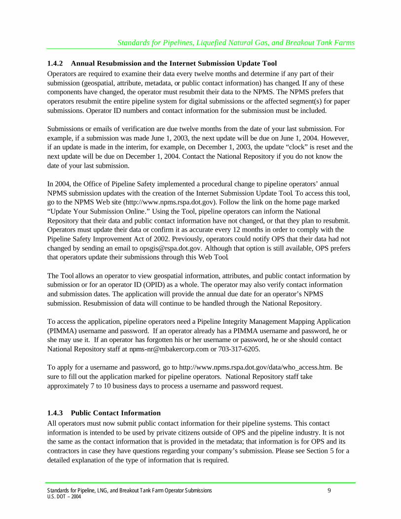
1.4.2 Annual Resubmission and the Internet Submission Update Tool Operators are required to examine their data every twelve months and determine if any part of their submission (geospatial, attribute, metadata, or public contact information) has changed. If any of these components have changed, the operator must resubmit their data to the NPMS. The NPMS prefers that operators resubmit the entire pipeline system for digital submissions or the affected segment(s) for paper submissions. Operator ID numbers and contact information for the submission must be included. Submissions or emails of verification are due twelve months from the date of your last submission. For example, if a submission was made June 1, 2003, the next update will be due on June 1, 2004. However, if an update is made in the interim, for example, on December 1, 2003, the update “clock” is reset and the next update will be due on December 1, 2004. Contact the National Repository if you do not know the date of your last submission. In 2004, the Office of Pipeline Safety implemented a procedural change to pipeline operators’ annual NPMS submission updates with the creation of the Internet Submission Update Tool. To access this tool, go to the NPMS Web site (http://www.npms.rspa.dot.gov). Follow the link on the home page marked “Update Your Submission Online.” Using the Tool, pipeline operators can inform the National Repository that their data and public contact information have not changed, or that they plan to resubmit. Operators must update their data or confirm it as accurate every 12 months in order to comply with the Pipeline Safety Improvement Act of 2002. Previously, operators could notify OPS that their data had not changed by sending an email to [email protected]. Although that option is still available, OPS prefers that operators update their submissions through this Web Tool. The Tool allows an operator to view geospatial information, attributes, and public contact information by submission or for an operator ID (OPID) as a whole. The operator may also verify contact information and submission dates. The application will provide the annual due date for an operator’s NPMS submission. Resubmission of data will continue to be handled through the National Repository. To access the application, pipeline operators need a Pipeline Integrity Management Mapping Application (PIMMA) username and password. If an operator already has a PIMMA username and password, he or she may use it. If an operator has forgotten his or her username or password, he or she should contact National Repository staff at [email protected] or 703-317-6205. To apply for a username and password, go to http://www.npms.rspa.dot.gov/data/who_access.htm. Be sure to fill out the application marked for pipeline operators. National Repository staff take approximately 7 to 10 business days to process a username and password request. 1.4.3 Public Contact Information All operators must now submit public contact information for their pipeline systems. This contact information is intended to be used by private citizens outside of OPS and the pipeline industry. It is not the same as the contact information that is provided in the metadata; that information is for OPS and its contractors in case they have questions regarding your company’s submission. Please see Section 5 for a detailed explanation of the type of information that is required.

Standards for Pipelines, Liquefied Natural Gas, and Breakout Tank Farms
Standards for Pipeline, LNG, and Breakout Tank Farm Operator Submissions 10 U.S. DOT – 2004
1.5 Distribution of NPMS Data Federal, state, and local governmental agencies and the pipeline industry may access all or portions of the pipeline, LNG, and breakout tank farm layers of the NPMS. Other data layers on high consequence areas, transportation networks, and natural disaster probability areas are being collected from various governmental and private sources, and are available to the extent possible. The data collected for the NPMS is necessary for regulatory oversight and for monitoring pipeline security. Therefore, public access to the data is limited. One of the goals of the NPMS is to assist operators in progressing toward a digital mapping environment. Upon request, digital pipeline and LNG facility data will be provided back to the contributing operator at no cost. The format of the digital data will be determined between the receiving operator and the Repository. The Repository may charge a fee for other products and services. The data contained in the NPMS are for reference purposes only and are not to be construed as actual survey-quality data or as a replacement for contacting a one-call center. 1.6 About these Standards
These standards were created with input from the pipeline industry, governmental agencies, and the public. They address the submission of digital and hard-copy pipeline and LNG data to support the development of a reasonably accurate NPMS. Operators are responsible for providing data that complies with these standards. The goal of OPS is for the NPMS to support operators who want to develop digital geospatial data. Operators who anticipate having difficulty meeting NPMS standards are encouraged to contact the Repository. The Repository will work with the operator and OPS to formulate an acceptable submission. These standards serve as a guideline for preparing and submitting pipeline and LNG location and attribute data for inclusion in the NPMS Repository. The Repository understands that the availability of pipeline company maps and digital data varies among operators and that there is a need to be flexible when working with the pipeline operators. The Repository will review and approve variations of data submissions from this standard on a case-by-case basis. The following sections discuss in detail the format, content, and quality of pipeline and LNG facility data that are to be submitted for inclusion into the NPMS. The standards provide guidelines for the submission of both digital and hard copy data. The NPMS prefers that the data provided by the operator be in digital format. If digital data are not available, then hard-copy submissions are acceptable. Three types of data are required: geospatial data (location information), attribute data (descriptive information), and metadata (data about the data). Contact information for the pipeline operator is also required. See Section 5 for more details about contact information.

Standards for Pipelines, Liquefied Natural Gas, and Breakout Tank Farms
Standards for Pipeline, LNG, and Breakout Tank Farm Operator Submissions 11 U.S. DOT – 2004
2. General Requirements (Key Terms and Definitions) This section establishes general NPMS terms and requirements.
Geospatial Data Attribute Data Metadata Contact Information
Digital or hard-copy maps with lines and/or points marking the location of pipelines, LNG facilities, and breakout tanks.
A computer database containing descriptive information about pipelines or LNG facilities. There is one record in the database for each pipeline segment.
Descriptive information about how the geospatial and attribute data were prepared (i.e., data about data). “This map and database were prepared by ABC Pipeline Company using aerial photography and GPS…”
Information about the person or entity who serves as a contact for the pipeline system. Contains either the person’s name and title or the name of an entity. Also contains address, phone, and email information.
Figure 2-1. The types of NPMS data. The NPMS will include natural gas transmission lines, hazardous liquid trunklines, LNG facilities, and breakout tanks. Information on other types of pipelines and facilities need not be submitted at this time. Natural gas transmission line – A pipeline system, other than a gathering line, that
1. Transports gas from a gathering line or storage facility to a distribution center, storage facility, or large-volume customer that is not downstream from a distribution center. A large-volume customer may receive similar volumes of gas as a distribution center. Factories, power plants, and institutional users of gas are included.
2. Operates at a hoop stress of 20 percent or more of specified minimum yield strength (SMYS) or
3. Transports gas within a storage field. Hazardous liquid – Petroleum, petroleum products, or anhydrous ammonia. Hazardous liquid trunkline – A hazardous liquid transmission pipeline other than a flow line, gathering line, or in-plant pipeline. Liquefied natural gas (LNG) – Natural gas or synthetic gas, having methane as its major constituent, that has been changed to a liquid or semi-solid.
Pipeline Attribute Table
Descriptive Field 1
Descriptive Field 2
Descriptive Field …
LNG Attribute Table
Descriptive Field 1 …
Pipeline
LNGPLANT

Standards for Pipelines, Liquefied Natural Gas, and Breakout Tank Farms
Standards for Pipeline, LNG, and Breakout Tank Farm Operator Submissions 12 U.S. DOT – 2004
LNG facility – A pipeline facility that is used for liquefying or solidifying natural gas or transferring, storing, or vaporizing liquefied natural gas. Pipeline system – All parts of a natural gas transmission line or hazardous liquid trunkline through which gas or hazardous liquid is transported. By definition, only one firm can operate a pipeline system. Operators should assign unique names to each of their pipeline systems. A pipeline system may have an unlimited number of branches. Each pipeline system must be represented by one or more pipeline segments.
Figure 2-2. Sample of annotated pipeline system. Pipeline segment – A linear feature representing part or all of a pipeline system on a digital or hard-copy map. A pipeline segment must have only two ends. No branches are allowed. A pipeline segment may be a straight line or may have any number of vertices. Each pipeline segment must be uniquely identified. The number of pipeline segments should be kept to the minimum needed to represent a pipeline system and its associated attributes. When submitting hard-copy maps, the beginning and ending points of each pipeline segment should be marked with a clear, visible dot. When submitting digital geospatial data, a unique line segment in the computer-aided drafting (CAD) or GIS data set should represent each pipeline segment.
Figure 2-3. A pipeline sys tem consisting of three pipeline segments. A pipeline system should be broken into multiple pipeline segments for only two reasons:
1. to represent a branch or intersection with another pipeline segment, and/or
2. to allow for a change of associated attributes such as diameter. Pipeline intersection – A point where a physical connection between two pipelines occurs. A commodity from one pipeline can flow into another pipeline(s), either through a branch within a pipeline system or a connection between two pipe line systems. When submitting hard-copy maps, intersections should be
A B C Pipeline System
1
3
2
Pipeline Segments 1,2,3

Standards for Pipelines, Liquefied Natural Gas, and Breakout Tank Farms
Standards for Pipeline, LNG, and Breakout Tank Farm Operator Submissions 13 U.S. DOT – 2004
marked with a clear, visible dot. When submitting digital geospatial data, line segments in the CAD or GIS data set should be broken at the point of intersection. The intersection will be a common endpoint (node) representing the two pipeline segments. Pipeline crossing – A point where two or more pipelines cross, but where there is no physical connection between the pipelines. Pipeline segments should not be broken at pipeline crossings. Pipeline crossings should not be marked with a dot.
Figure 2-4. Sample annotation of pipeline intersection and pipeline crossing.
Pipeline corridor – A pipeline corridor is a linear area where two or more pipelines (either part of the same or different pipeline systems) are closely grouped in a single right-of-way. Pipeline corridors pose a cartographic challenge and the NPMS handles them differently on hard-copy and digital maps. On hard-copy maps, a single line with multiple annotations may represent the multiple pipelines within a pipeline corridor. In digital files, multiple lines are required, and each separate representation must be stored in individual layers or files. Whether submitting hard-copy or digital geospatial data, pipeline corridors should be clearly annotated, particularly where pipelines join or exit the corridor. Breakout tank– A tank used to a) relieve surges in a hazardous liquid pipeline system or b) receive and store hazardous liquid transported by a pipeline for reinjection and continued transportation.
Pipeline Intersection Pipeline Crossing

Standards for Pipelines, Liquefied Natural Gas, and Breakout Tank Farms
Standards for Pipeline, LNG, and Breakout Tank Farm Operator Submissions 14 U.S. DOT – 2004
2.1 NPMS File Naming Conventions Operators are requested to use the following formula when assigning file names:
Type of File Code + OPID + hyphen + 4-Digit Sequential Number + 3-Digit Alphanumeric Extension
Sample file name: G12345-0001.DWG Type of File Code (one -character, alpha):
G = Geospatial Data Only
A = Attribute Data Only
B = Both Geospatial and Attribute Data
(Also use “B” when different geospatial and attribute files should have the same name. For example, an export from ESRI’s ArcView software might have the following names: B12345-0001.SHP, B12345-0001.SHX, B12345-0001.DBF.)
M = Metadata OPID (five digits [maximum], numeric) – This is the identification number assigned by the Office of Pipeline Safety to pipeline and LNG facility operators, for user-fee purposes. The OPID has five digits or fewer. If you don’t know your OPID, check the NPMS Web site. 4-Digit Sequential Number (one-digit, numeric) – This is used to avoid assigning several files with the same file name. Extension (three-character default from software package) – Use the default extension for export from the software package (e.g., .DWG, .SHP, .DBF, etc.). 2.2 Types of NPMS Submissions Operators must classify submissions according to one of the following types. Operators planning to make a submission that combines submission types should contact the Repository prior to preparing the submission. The various types of submissions are intended to facilitate maintenance of the NPMS and minimize the effort required by pipeline operators. Additions – Additions contain only data that is new to the NPMS. All original submissions are additions. All additions should contain geospatial data, attribute data, and metadata. The revision codes (REVIS_CD) of all pipeline segments should be set to “A” for addition. Modifications – Operators with digital information should submit the entire dataset again when modifications occur. Operators with hard-copy information may include only modified data. There are three types of NPMS modifications. Operators should inform the Repository of the type of modification being made.
1. A geospatial modification is used if location data or location and attribute are to be modified. All geospatial modifications should contain geospatial data, attribute data, and metadata. The revision
Standards for Pipelines, Liquefied Natural Gas, and Breakout Tank Farms
Standards for Pipeline, LNG, and Breakout Tank Farm Operator Submissions 15 U.S. DOT – 2004
codes (REVIS_CD) of all pipeline segments and/or LNG facilities should be set to “M” for modification or “D” for deletion.
2. An attribute only modification is used if modifications only affect pipeline or LNG facility attributes. Attribute only modifications should contain attribute data, metadata, and a letter identifying the affected pipeline systems (SYS_NM) or individual pipeline segments. The revision codes (REVIS_CD) of all pipeline segments and LNG facilities should be set to “M” for modification.
3. A contact information only modification is used to report name changes, address changes, or updates to other operator contact information. It is now possible to connect to the NPMS Web site and update the contact information online. The Repository will confirm the changes via email. See Section 5 for more information about updating or entering contact information.
4. A metadata only modification is used if modifications only affect metadata. This might include a name change of the technical contact. Metadata only modifications should contain a complete replacement metadata file, and a letter identifying the affected pipeline systems (SYS_NM) or individual pipeline segments.
Change of Operator Report – The operators of any given pipeline system may change frequently. When this occurs, both old and new operators should report the change using the NPMS Web site or send correspondence. The Repository will confirm any changes. Change Pipeline System Status – If any entire pipeline system operates sporadically or the transported commodities change, NPMS should be notified via the Web site or by correspondence.

Standards for Pipelines, Liquefied Natural Gas, and Breakout Tank Farms
Standards for Pipeline, LNG, and Breakout Tank Farm Operator Submissions 16 U.S. DOT – 2004
3. Attribute Data When submitting data to the Repository, the operator is required to provide descriptive information about the pipelines and LNG facilities. The attribute data is essential information about the pipeline or LNG facility such as its name and commodity transported. To simplify the submission, the required attribute data has been kept to a minimum. 3.1 Required and Optional Attributes
Each pipeline segment or LNG facility submitted must be accompanied by a corresponding record and attribute database table. For information about required and optional attributes, refer to the following figures:
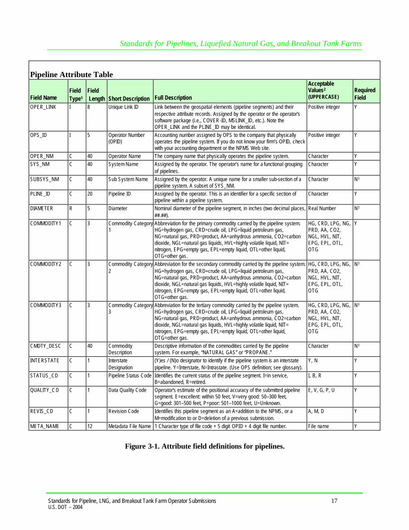
t For pipeline submissions, see Figure 3-1 for the attribute field definitions.
t For LNG submissions, see Figure 3-2 for the attribute field definitions. 3.2 Rules for Attribute Data Input When submitting digital attribute information, adhere to the following rules:
1. Use only UPPERCASE when defining field names.
2. Use only UPPERCASE when inputting data into the attribute tables.
3. Omit all punctuation except for periods (.), spaces ( ), backslashes (\), colons (:), commas (,), hyphens (-), and underscores ( _ ). Semicolons (;) should be used only as a delimiter when submitting attribute data in ASCII-delimited text files.
4. Use only NPMS-specified abbreviations.
5. Be consistent. Names and terms should be exactly replicated throughout a submission. For example, if a pipeline system is named Pennsylvania Line (SYS_NM = “Pennsylvania Line”), the operator should consistently use the full and exact name. The operator should not use alternative names like “Penn Line” or “PA Line” or “Pennsylvania.”
6. Use the correct OPID. OPID is an accounting number assigned by the U.S. Department of Transportation, Office of Pipeline Safety to firms that operate pipelines and LNG facilities. If you do not know your firm’s OPID number, check with your firm’s accounting department. A list of valid OPIDs is also posted on the NPMS Web site.
Standards for Pipelines, Liquefied Natural Gas, and Breakout Tank Farms
Standards for Pipeline, LNG, and Breakout Tank Farm Operator Submissions 17 U.S. DOT – 2004
Pipeline Attribute Table
Field Name
Field Type1
Field Length
Short Description
Full Description
Acceptable Values2 (UPPERCASE)
Required Field
OPER_LINK I 8 Unique Link ID Link between the geospatial elements (pipeline segments) and their respective attribute records. Assigned by the operator or the operator's software package (i.e., COVER-ID, MSLINK_ID, etc.). Note the OPER_LINK and the PLINE_ID may be identical.
Positive integer Y
OPS_ID I 5 Operator Number (OPID)
Accounting number assigned by OPS to the company that physically operates the pipeline system. If you do not know your firm’s OPID, check with your accounting department or the NPMS Web site.
Positive integer Y
OPER_NM C 40 Operator Name The company name that physically operates the pipeline system. Character Y SYS_NM C 40 System Name Assigned by the operator. The operator's name for a functional grouping
of pipelines. Character Y
SUBSYS_NM C 40 Sub System Name Assigned by the operator. A unique name for a smaller sub-section of a pipeline system. A subset of SYS_NM.
Character N3
PLINE_ID C 20 Pipeline ID Assigned by the operator. This is an identifier for a specific section of pipeline within a pipeline system.
Character Y
DIAMETER R 5 Diameter Nominal diameter of the pipeline segment, in inches (two decimal places, ##.##).
Real Number N3
COMMODITY1 C 3 Commodity Category 1
Abbreviation for the primary commodity carried by the pipeline system. HG=hydrogen gas, CRD=crude oil, LPG=liquid petroleum gas, NG=natural gas, PRD=product, AA=anhydrous ammonia, CO2=carbon dioxide, NGL=natural gas liquids, HVL=highly volatile liquid, NIT= nitrogen, EPG=empty gas, EPL=empty liquid, OTL=other liquid, OTG=other gas.
HG, CRD, LPG, NG, PRD, AA, CO2, NGL, HVL, NIT, EPG, EPL, OTL, OTG
Y
COMMODITY2 C 3 Commodity Category 2
Abbreviation for the secondary commodity carried by the pipeline system. HG=hydrogen gas, CRD=crude oil, LPG=liquid petroleum gas, NG=natural gas, PRD=product, AA=anhydrous ammonia, CO2=carbon dioxide, NGL=natural gas liquids, HVL=highly volatile liquid, NIT= nitrogen, EPG=empty gas, EPL=empty liquid, OTL=other liquid, OTG=other gas.
HG, CRD, LPG, NG, PRD, AA, CO2, NGL, HVL, NIT, EPG, EPL, OTL, OTG
N3
COMMODITY3 C 3 Commodity Category 3
Abbreviation for the tertiary commodity carried by the pipeline system. HG=hydrogen gas, CRD=crude oil, LPG=liquid petroleum gas, NG=natural gas, PRD=product, AA=anhydrous ammonia, CO2=carbon dioxide, NGL=natural gas liquids, HVL=highly volatile liquid, NIT= nitrogen, EPG=empty gas, EPL=empty liquid, OTL=other liquid, OTG=other gas.
HG, CRD, LPG, NG, PRD, AA, CO2, NGL, HVL, NIT, EPG, EPL, OTL, OTG
N3
CMDTY_DESC C 40 Commodity Description
Descriptive information of the commodities carried by the pipeline system. For example, “NATURAL GAS” or “PROPANE.”
Character N3
INTERSTATE C 1 Interstate Designation
(Y)es / (N)o designator to identify if the pipeline system is an interstate pipeline. Y=Interstate, N=Intrastate. (Use OPS definition; see glossary).
Y, N Y
STATUS_CD C 1 Pipeline Status Code Identifies the current status of the pipeline segment. I=in service, B=abandoned, R=retired.
I, B, R Y
QUALITY_CD C 1 Data Quality Code Operator's estimate of the positional accuracy of the submitted pipeline segment. E=excellent: within 50 feet, V=very good: 50–300 feet, G=good: 301–500 feet, P=poor: 501–1000 feet, U=Unknown.
E, V, G, P, U Y
REVIS_CD C 1 Revision Code Identifies this pipeline segment as an A=addition to the NPMS, or a M=modification to or D=deletion of a previous submission.
A, M, D Y
META_NAME C 12 Metadata File Name 1 Character type of file code + 5 digit OPID + 4 digit file number. File name Y
Figure 3-1. Attribute field definitions for pipelines.

Standards for Pipelines, Liquefied Natural Gas, and Breakout Tank Farms
Standards for Pipeline, LNG, and Breakout Tank Farm Operator Submissions 18 U.S. DOT – 2004
LNG Facility Attribute Table Field Name
Field Type1
Field Length
Short Description
Full Description
Acceptable Values2
(UPPERCASE)
Required Field
OPER_LINK I 8 Unique Link ID Link between the geospatial elements (points) and their respective attribute records. Assigned by the operator or the operator's software package (i.e., COVER-ID, MSLINK_ID, etc.). Note the OPER_LINK and the LNG_ID can be identical.
Positive integer Y
OPS_ID I 5 Operator Number (OPID)
Accounting number assigned by OPS to the company that physically operates the LNG facility. If you do not know your firm’s OPID, check with your accounting department.
Positive integer Y
OPER_NM C 40 Operator Name The name of the company that physically operates the facility.
Character Y
LNG_NM C 40 LNG Facility Name Assigned by the operator. The operator's name for the LNG facility.
Character Y
LNG_ID C 20 LNG Facility ID Assigned by the operator. This is a unique identifier for a specific facility.
Character Y
STATUS_CD C 1 LNG Status Code Identifies the current status of the facility. I=in service, B=abandoned, R=retired.
I, B, R Y
QUALITY_CD C 1 Data Quality Code Operator's estimate of the positional accuracy of the submitted facility data. E=excellent: within 50 feet, V=very good: 50–300 feet, G=good: 301–500 feet, P=poor: 501–1000 feet, U=Unknown.
E, V, G, P, U Y
REVIS_CD C 1 Revision Code Identifies this facility as A=addition to the NPMS, M=modification to or D=deletion of a previous submission.
A, M, D Y
META_NAME C 12 Metadata File Name 1 Character type of file code + 5 digit OPID + 4 digit file number.
File name Y
NOTES: 1 I – Integer; C – Character. 2 Field must be UPPERCASE.
Figure 3-2. Attribute field definitions for LNG facilities.

Standards for Pipelines, Liquefied Natural Gas, and Breakout Tank Farms
Standards for Pipeline, LNG, and Breakout Tank Farm Operator Submissions 19 U.S. DOT – 2004
Understanding Pipeline System and Pipeline Segment Attributes Some NPMS attributes refer to entire pipeline systems, while other attributes may refer only a portion of a pipeline system. For example , the INTERSTATE field obviously refers to the pipeline system as a whole, not its individual pipeline segments. Therefore, the INTERSTATE field must contain the same value for every pipeline segment that is included in a pipeline system. On the other hand, a field such as DIAMETER can change during the course of a pipeline system. In such cases, a new pipeline segment with the appropriate value for DIAMETER must be created. The following fields must contain the same value for every pipeline segment included in a pipeline system:
OPID OPER_NM SYS_NM COMMODITY1 COMMODITY2 COMMODITY3 CMDTY_DESC INTERSTATE META_NAME
Fields that may contain a different value for each pipeline segment include: OPER_LINK (must be unique for each segment) SUB_SYS_NM PLINE_ID DIAMETER STATUS_CD REVIS_CD 3.3 Building the Attribute Data File Attribute data may be provided in one of the following formats: common GIS export, DBASE (.DBF) format, Microsoft Access (.MDB), American Standard Code for Information Interchange (ASCII) text file, or annotation on a hard-copy map. In all cases, operators should be careful to follow the field name, field type, and field length standards listed in Figures 3-1 and 3-2. The Office of Pipeline Safety has developed an NPMS Attribute Data Template. The software operates on Windows personal computers and manages attribute data entry. The software produces properly formatted Microsoft Access files for NPMS submission.
t Common GIS export format – Operators using GIS systems can package attribute data with the associated geospatial data. Acceptable GIS formats are discussed in Section 4.1, General Requirements for Digital Geospatial Data.
t DBASE (.DBF) format – Operators can create a .DBF file using one of the commercially available software packages that writes to a .DBF file. Options include Excel, Access, Fox Pro, Lotus 123, Dbase, and Paradox.

Standards for Pipelines, Liquefied Natural Gas, and Breakout Tank Farms
Standards for Pipeline, LNG, and Breakout Tank Farm Operator Submissions 20 U.S. DOT – 2004
t Microsoft Access (.MDB) − Operators can use the NPMS Attribute Data Template to create a properly formatted .MDB file for submission.
t ASCII format – The file should be semicolon-delimited.
t Annotation format – See Section 4.3, Hard-Copy Submissions, for procedures on annotating attributes on hard-copy maps.
3.4 Using The NPMS Attribute Data Template The NPMS Attribute Data Template software is available at no cost. The software can be downloaded from the NPMS Web site and is available on CD. The software simplifies the creation of NPMS attribute data by minimizing repetition and handling all formatting issues. 3.4.1 System Requirements The system requirements are a 486 processor (or higher) personal computer that uses Microsoft Windows 95, or later. The system should have at least 8 megabytes of RAM and a CD-ROM drive. 3.4.2 Installation Instructions Before installing any version of NPMS software, close all open programs. Also, if you are running an older copy of the NPMS software and are attempting to install a new version, uninstall the existing NPMS software before proceeding with these steps. From CD-ROM:
1. Insert the CD-ROM.
2. From Windows Explorer, double click on Setup.exe.
3. Follow the on-screen installation instructions.
Note: The CD-ROM also contains these standards in Adobe Portable Document Format (.PDF) and Adobe Acrobat Reader, which is required to view or print the document.
From the Internet:
1. Create a directory on your system’s hard drive called “C:\Program Files\NPMS.”
2. Download the file “NPMS.EXE” from the NPMS Web site and copy the file in the C:\Program Files\NPMS directory.
3. From Windows Explorer double click on NPMS.EXE. (NPMS.EXE is a group of compressed files. Double clicking will cause the file to uncompress.)
4. Double click on C:\Program Files\NPMS\Setup.exe.
5. Follow the on-screen installation instructions. 3.4.3 Step-by-Step User Instructions The NPMS Attribute Data Template simplifies data entry by minimizing repetition. To use the data template, follow the instructions below.
1. From the Start/Programs menu, click on the NPMS Attribute icon to start the program.

Standards for Pipelines, Liquefied Natural Gas, and Breakout Tank Farms
Standards for Pipeline, LNG, and Breakout Tank Farm Operator Submissions 21 U.S. DOT – 2004
Figure 3-3. Attribute data entry screen.
2. The initial screen requires the user to select the correct OPID. A list of valid operator names and OPIDs is provided. If you do not know what your OPID is, contact Shauna Turnbull at 202-366-3731. If your operator ID does not appear on the drop-down list, go to the Tools Menu and click on “Update OPID.” When the update is finished, try the drop-down list again. If your OPID still does not appear, contact National Repository staff at 703-317-6205. The initial metadata screen also allows the user to either edit an existing metadata file or to start a new file.
3. If there is existing data for the operator you have selected and the submission is located in the current working directory, the default table for the chosen operator will appear in the “Browse” box. “Edit Existing Submission” will be the default choice. Data fields shown with a yellow background are required; while data fields shown with a white background are optional. Decide if you want to edit an existing file or start a new file. NPMS data is stored in the same directory where the software was installed, usually C:\Program Files\NPMS.
Note: If there is existing data for the operator you have selected and the submission is located in the current working directory, the default table for the chosen operator will appear in the “Browse” box, and “Edit Existing Submission” will be the default choice of action. If you are creating a new submission, select that option and a new table will be created for the operator submission you have chosen.
4. Select attribute data entry for either pipeline systems or LNG facilities.

Standards for Pipelines, Liquefied Natural Gas, and Breakout Tank Farms
Standards for Pipeline, LNG, and Breakout Tank Farm Operator Submissions 22 U.S. DOT – 2004
Figure 3-4. Pipeline attributes data entry screen.
If “Pipeline System Attributes” was selected on the initial screen,
5. Complete information for the pipeline system as a whole. The upper section contains information that needs to be completed only once for each pipeline system. This includes the system name, information about the commodities transported by the system, the system’s interstate/intrastate status, and the associated metadata file created with the NPMS Metadata Template.
6. Complete information for the associated pipeline segments. When all the required information in the upper portion has been completed, go to the lower portion of the screen to add information about the individual pipeline segments that comprise the pipeline system. Remember, each pipeline system must have at least one pipeline segment. The lower portion allows the operator to record information about items that may change during the course of the pipeline system, such as PIPELINE_ID (PLINE_ID), SUBSYSTEM NAME (SUBSYS_NM), and DIAMETER. It is expected that when information does not change, values will be repeated for each pipeline segment. However, OPER_LINK cannot be duplicated. Each pipeline segment must have a unique OPER_LINK value. To delete a pipeline segment, highlight the row by clicking on the far left side of the grid and press the delete key.
7. “Previous” and “Next” buttons allow forward and backward movement among previously added pipeline systems. The upper left corner of the form will indicate which system number you are on and how many systems exist. To add a system, click on the “Add” button and fill out the attribute
Standards for Pipelines, Liquefied Natural Gas, and Breakout Tank Farms
Standards for Pipeline, LNG, and Breakout Tank Farm Operator Submissions 23 U.S. DOT – 2004
data completely. If, at any time, you wish to cancel your addition, click on the “Cancel” button. You will return to the previous pipeline system, and the addition will not be saved.
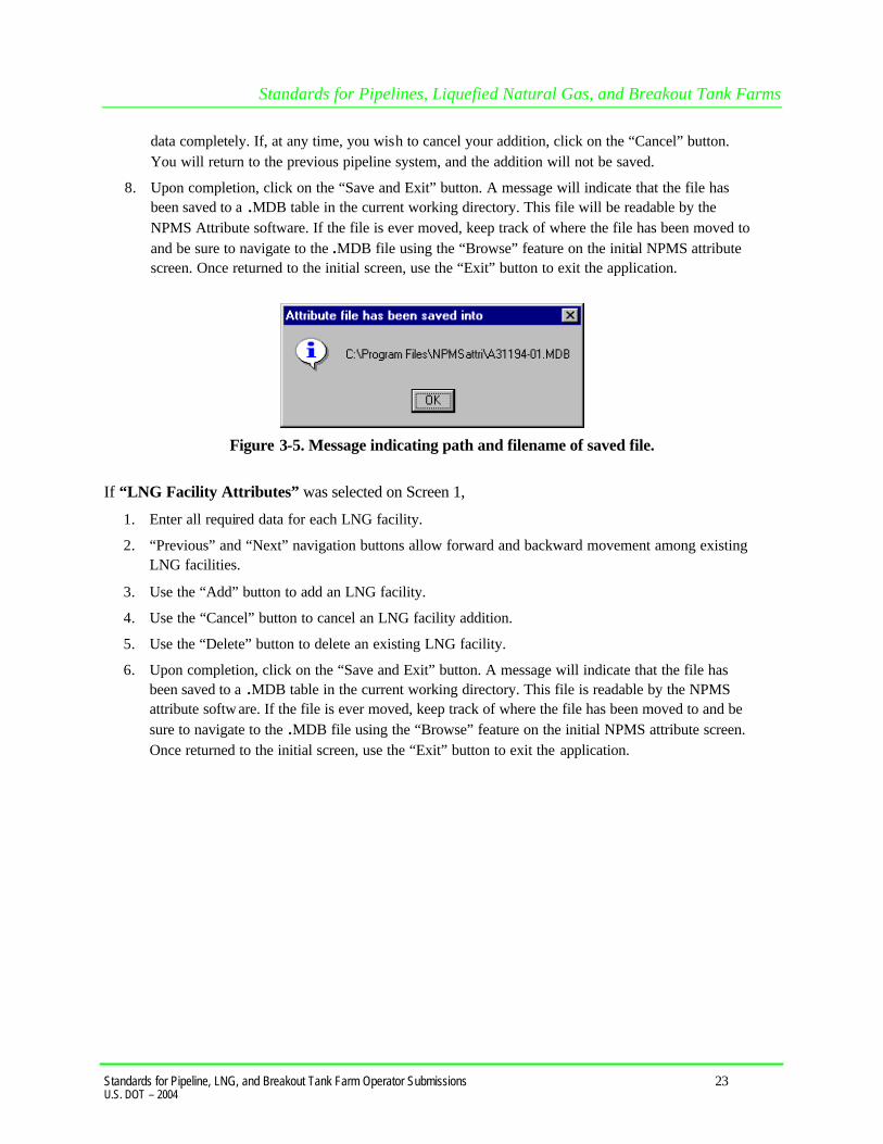
8. Upon completion, click on the “Save and Exit” button. A message will indicate that the file has been saved to a .MDB table in the current working directory. This file will be readable by the NPMS Attribute software. If the file is ever moved, keep track of where the file has been moved to and be sure to navigate to the .MDB file using the “Browse” feature on the initial NPMS attribute screen. Once returned to the initial screen, use the “Exit” button to exit the application.
Figure 3-5. Message indicating path and filename of saved file.
If “LNG Facility Attributes” was selected on Screen 1,
1. Enter all required data for each LNG facility.
2. “Previous” and “Next” navigation buttons allow forward and backward movement among existing LNG facilities.
3. Use the “Add” button to add an LNG facility.
4. Use the “Cancel” button to cancel an LNG facility addition.
5. Use the “Delete” button to delete an existing LNG facility.
6. Upon completion, click on the “Save and Exit” button. A message will indicate that the file has been saved to a .MDB table in the current working directory. This file is readable by the NPMS attribute softw are. If the file is ever moved, keep track of where the file has been moved to and be sure to navigate to the .MDB file using the “Browse” feature on the initial NPMS attribute screen. Once returned to the initial screen, use the “Exit” button to exit the application.

Standards for Pipelines, Liquefied Natural Gas, and Breakout Tank Farms
Standards for Pipeline, LNG, and Breakout Tank Farm Operator Submissions 24 U.S. DOT – 2004
Figure 3-6. LNG facility attributes data entry.

Standards for Pipelines, Liquefied Natural Gas, and Breakout Tank Farms
Standards for Pipeline, LNG, and Breakout Tank Farm Operator Submissions 25 U.S. DOT – 2004
4. Geospatial Data (Digital or Hard-Copy Maps) Geospatial data represent pipeline systems (linear) and LNG facility (point) elements. Pipeline and LNG facility data may be submitted in either digital or hard-copy format. All submissions should meet the ±500-foot accuracy standard. 4.1 General Requirements for Digital Geospatial Data
The following discusses various requirements and formats that operators should meet when submitting digital geospatial data.
1. Use a real world coordinate system based on North American Datum (NAD) 1983 or NAD 1927. The Repository accepts unprojected data in decimal degrees and data that employs a common projection scheme such as Universal Transverse Mercator (UTM) or State Plane. Projected data may employ either English (feet) or metric (meters) measurement units. In all cases, clearly state the datum, coordinate system/ projection, and measurement units in the accompanying metadata.
Note: Digital data that does not employ real world coordinates, such as CAD files that employ an origin point of 0,0 in the lower left hand corner of the drawing cannot be accepted by the Repository.
2. Provide spatially accurate data. NPMS strives for minimum accuracy of ±500 feet. Base maps or other source materials used to develop digital geospatial data submissions should have a scale between 1:24,000 (1" = 2,000’) and 1:1,200 (1" = 100'). The spatial accuracy of the digital submission should be clearly stated in the accompanying metadata.
3. Always submit pipeline systems (lines) and LNG facilities (points) in separate files.
4. Submit only qualifying pipeline and LNG facility data. The submitted digital file should contain only pipeline segments representing natural gas transmission lines, hazardous liquid trunklines, and points representing LNG facilities. Separate all other data such as gathering lines, spur lines, valves, and base map data such as buildings, roads, property lines, political boundaries, scanned images, etc. Note: Curves should be represented by a pipeline segment with as many vertices/shape points as is required to provide the appropriate cartographic appearance. CAD system arcs should be avoided.
5. Ensure that the reproduction and submission of any map or data does not violate existing copyright laws.
6. Review data for quality. Common problems include: a. overshoots and undershoots at pipeline intersections, b. stray points and lines that do not represent a pipeline or LNG facilities, often left from deleting
non-NPMS data, and/or c. duplicate points and lines.
7. Use commonly accepted digital media. The Repository accepts CD-ROMs, diskettes, zip disks, and Internet transmissions. Check the NPMS Web site for details.

Standards for Pipelines, Liquefied Natural Gas, and Breakout Tank Farms
Standards for Pipeline, LNG, and Breakout Tank Farm Operator Submissions 26 U.S. DOT – 2004
4.2 Digital Submission Techniques The instructions below provide general assistance to operators using some of the more popular GIS and CAD software packages. Some currently available GIS formats are not discussed, but may be acceptable. Operators interested in submitting data in a format not provided for in these instructions should contact the Repository to determine its acceptability. The instructions may not correspond to the exact version of the software package the operator is using, nor do they reflect any software customizations that may have been made. Operators who encounter problems are encouraged to contact their software vendor for technical support. 4.2.1 ESRI ArcInfo Format Data Submissions Data from ESRI’s ArcInfo may be submitted to the NPMS in Export (.E00) format. The following describes how coverages must be prepared before the data files are constructed to ensure that they are received and processed correctly. Steps for preparing an Export (.E00) File follow.
1. Isolate the data to be submitted to the NPMS in a separate coverage.
2. Store the coverage as double precision. Use the Arc COPY command with the DOUBLE option to create double-precision coverages.
3. If not already done, use the PROJECTDEFINE command to define the coverage’s projection information.
4. If the attribute data are stored in an external Lookup Table (LUT), the NPMS requests that the attribute data be attached to the coverage to lessen the opportunity for data corruption. To attach the LUT files, use the Arc JOINITEM command based on some common identifier.
5. If not already present, create arc topology using the BUILD command for lines.
6. Use the Arc EXPORT command to generate the .E00 file.
7. Submit the .E00 file to the NPMS.
4.2.2 ESRI ArcView Format Data Submissions Operators may submit data to the NPMS using the shapefile format of ESRI’s ArcView desktop software. The following describes how shapefiles must be prepared:
1. Isolate the data to be submitted to the NPMS into a single line (pipeline) or point (LNG facility) theme.
2. Use the “Convert to Shapefile” command on the Theme menu to export the data. This will create three files (.SHP, .SHX, .DBF).
3. Submit all three files, the .SHP (geospatial data file), the .SHX (index file), and the .DBF (attribute data file) for each shape theme to the NPMS.
4.2.3 Intergraph Corporation’s FRAMME Data Submissions Data from an Intergraph AM/FM/GIS system that uses the FRAMME database architecture can be provided to the NPMS in several different formats. However, the two that the Repository prefers are 1)

Standards for Pipelines, Liquefied Natural Gas, and Breakout Tank Farms
Standards for Pipeline, LNG, and Breakout Tank Farm Operator Submissions 27 U.S. DOT – 2004
Microsoft Access format and 2) FRAMME Loader SEF format (a structured ASCII file format). These two approaches are described below. Microsoft Access Format. Intergraph offers a viewing/analysis product called GeoMedia that allows users to access and perform analysis operations on various GIS databases (including data stored in FRAMME, ArcInfo, ArcView, Oracle Spatial Data Cartridge/Spatial Data Option, MGE, and Microsoft Access). It can also extract data from any of these databases and store it in a local Microsoft Access database file format. The process to create this Access file follows:
1. Make a warehouse connection to the GIS database (FRAMME).
2. Create an empty Access database file warehouse using GeoMedia.
3. Define the coordinate system of the Access warehouse as Geographic (Lat/Long) and NAD 83 Datum. Many other coordinate system definitions are also supported.
4. Isolate the data to be submitted to the NPMS. A subset of the GIS data may be identified by means of attribute and/or spatial queries. This will create a named query set.
5. Import data from either the GIS database or from the named query set into the Access warehouse. On import, the data will be transformed from whatever native coordinate system it is stored in to the desired Geographic NAD83 format. The Access file will contain both feature attributes and graphic definitions.
FRAMME Loader SEF Format. FRAMME’s normal method of bulk data import and export is a product module called FRAMME Loader. It supports both loading and unloading of ASCII text files. These text files must be in a structured format called Standard Exchange Format (SEF). The SEF file contains both feature attributes and graphic definitions. The basic process to create the SEF file follows.
1. From within FRAMME, isolate the data to be exported using the feature extraction process.
2. Unload the extracted data using FRAMME Loader capabilities. 4.2.4 Intergraph / Bentley Corporation’s Microstation and
non-FRAMME Data Submissions Operators may submit geospatial data using Microstation/Intergraph systems. The following procedures have been developed to help operators submit this type of data. Because it is difficult to attach attribute data to Microstation/Intergraph drawing files, the following tasks must be performed before providing data to the NPMS Repository:
1. Isolate the data to be submitted to the NPMS.
2. Annotate a unique item, OPER_LINK, for each pipeline or LNG facility as a text element in the drawing. The OPER_LINK value must be located adjacent to the pipeline or facility that it identifies.
3. Save the drawing as a .DGN file. Create an attribute data table using the NPMS Attribute Data Template software.
4. Enter the OPER_LINK identifier from the drawing and that pipeline’s or facility’s attribute data into the attribute table.

Standards for Pipelines, Liquefied Natural Gas, and Breakout Tank Farms
Standards for Pipeline, LNG, and Breakout Tank Farm Operator Submissions 28 U.S. DOT – 2004
5. Submit both the .DGN and the attribute table to the NPMS. For the .DGN file, also submit a schema or template for the levels used.
6. Include in the associated metadata any special instructions, such as map units, scale, seed file, font types, etc. that are associated with the .DGN file to help the NPMS process the data.
4.2.5 MapInfo Data Submissions Operators may submit data to the NPMS using the MapInfo Interchange File (MIF) format of MapInfo Corporation desktop software (Version 3 or higher). The projection must be noted: Category, Category Members, and Map Units (coordinate units, distance units, and area units).
1. Isolate the data to be submitted to the NPMS in a separate table.
2. Export the table (Table → export).
3. Submit the MIF, MID, and projection (ASCII format) files for each table to the NPMS. 4.2.6 AutoCAD Data Submissions Operators may submit geospatial data using AutoCAD systems containing geospatial data. The following procedures have been developed to assist operators in submitting this type of data.
1. Isolate the data to be submitted to the NPMS.
2. Because it is difficult to attach attribute data to CAD drawing files, the following tasks must be performed. Annotate a unique item, OPER_LINK, for each pipeline or LNG facility using either the LAYER or MS-ID field in the AutoCAD drawing.
3. Save the drawing as a Version 12 AutoCAD .DWG file. Ensure that the drawings are saved in “model space” and not in “paper space.” In other words, all drawings should be cross-referenced to the appropriate coordinate system before saving.
4. Create an attribute data table using the NPMS Attribute Data Template software. Add columns in the table for OPER_LINK and each of the attribute items required by the NPMS.
5. Enter the OPER_LINK identifier from the drawing and that pipeline’s or facility’s attribute data into the attribute table.
6. Submit both the .DWG and the attribute table to the NPMS. For the .DWG file, also submit a schema or template for the levels used.
7. Include in the associated metadata any special instructions, such as map units, scale, projection information, font types, etc. that are associated with the .DWG file to help the NPMS process the data.
By providing the AutoCAD and attribute data in these formats, the Repository will be able to use the OPER_LINK values to associate the pipeline and LNG facility features with their appropriate attributes. 4.2.7 Smallworld Data Submissions Operators may submit geospatial data using Smallworld. The following procedures have been developed to assist operators in submitting this type of data. It is important to note that the data must conform to the datum, projection, scale, and control requirements outlined in these standards.
1. Isolate the data (real world objects) to be submitted to the NPMS.

Standards for Pipelines, Liquefied Natural Gas, and Breakout Tank Farms
Standards for Pipeline, LNG, and Breakout Tank Farm Operator Submissions 29 U.S. DOT – 2004
2. Use the FME (Feature Manipulation Engine), an add-on package available from Smallworld or Safe Software Inc., to create an ArcInfo exchange (.E00) file.
3. Submit the .E00 file to the NPMS.
4.2.8 Generic (ASCII) Digital Data Submissions This type of submission will include a geospatial file containing coordinate data, an attribute file containing information associated with the pipeline(s) or LNG facility(ies), and a metadata file describing the data. The file formats for pipelines and LNG facilities are different. Both file formats are described below, including record layouts. Geospatial File for Pipeline Digital Data Submissions. To submit digital data for pipelines, the operator will create files matching the following format. The file format will include the unique identifier (OPER_LINK) on one line, followed by a coordinate pair (longitude and latitude). Additional coordinate pairs will be listed in order of appearance along the line segment until all coordinate pairs are displayed. The final coordinate pair for the line segment is to be followed by the word “END.” “END” designates the end of the coordinate information that comprises a line segment. Each line segment submitted must contain a minimum of two coordinate pairs to represent the beginning and end of a straight line. An additional “END” is required to designate the end of the file. The unique identifier (OPER_LINK) will link the geospatial location to the attribute information for each pipeline submitted. Header information, as shown in Figure 4-1, should not be included in the submitted file.

Standards for Pipelines, Liquefied Natural Gas, and Breakout Tank Farms
Standards for Pipeline, LNG, and Breakout Tank Farm Operator Submissions 30 U.S. DOT – 2004
Figure 4-1. Geospatial file containing pipeline information.
Longitude should be stated in decimal degrees (no projection), for every stored pipeline start, shape, and end point. A minimum of five decimal places is required. Western Hemisphere longitude should be a negative value. Acceptable values are -180.00000 to 0.00000. Northern Hemisphere latitude should be a positive value. Acceptable values are 0.00000 to 90.00000. Geospatial File for LNG Facility Digital Data Submissions. To submit digital data for LNG facilities, the operator will create files matching the following format. The geospatial file for LNG facilities will contain the unique identifier (OPER_LINK) plus the longitude and latitude values on a single line. The unique identifier (OPER_LINK) will link the geospatial location to the attribute information for each LNG facility submitted. The last line in the file must contain only the word “END.” Header information, as shown in Figure 4-2, should not be included in the submitted file. The location should reflect the approximate geographic center of the LNG facility. If the location depicts something other than the approximate center, note this in Question 3 of the Data Transmittal Form.
DESCRIPTION ASCII FILE FORMAT(Do not include this section in your file)
OPER_LINK 1 5 1LONGITUDE, LATITUDE PAIR - 9 4 . 5 7 6 4 1 5 , 3 2 . 9 1 1 6 5 8LONGITUDE, LATITUDE PAIR - 9 4 . 5 7 6 4 5 6 , 3 2 . 9 1 2 6 3 9END OF LINE END OPER_LINK 1 5 2LONGITUDE, LATITUDE PAIR - 9 4 . 4 5 6 4 1 5 , 3 3 . 0 0 1 6 5 8LONGITUDE, LATITUDE PAIR - 9 4 . 4 5 6 7 9 7 , 3 3 . 0 0 0 6 8 1LONGITUDE, LATITUDE PAIR - 9 4 . 4 5 7 1 0 8 , 3 3 . 0 0 0 2 8 4LONGITUDE, LATITUDE PAIR - 9 4 . 4 5 7 8 0 1 , 3 2 . 9 9 9 9 1 6END OF LINE ENDOPER_LINK 1 5 3LONGITUDE, LATITUDE PAIR - 9 4 . 4 5 7 8 0 1 , 3 2 . 9 9 9 9 1 6LONGITUDE, LATITUDE PAIR - 9 4 . 4 5 7 1 5 3 , 3 3 . 0 0 1 4 7 9LONGITUDE, LATITUDE PAIR - 9 4 . 4 5 6 8 8 3 , 3 3 . 0 0 2 6 3 9END OF LINE END
.
.
.OPER_LINK 1 5 1 9LONGITUDE, LATITUDE PAIR - 9 3 . 5 4 1 2 1 3 , 3 3 . 6 7 4 0 6 8LONGITUDE, LATITUDE PAIR - 9 3 . 5 4 1 4 1 6 , 3 3 . 6 7 4 5 9 7LONGITUDE, LATITUDE PAIR - 9 3 . 5 4 2 3 8 6 , 3 3 . 6 7 5 4 1 9LONGITUDE, LATITUDE PAIR - 9 3 . 5 4 5 6 0 4 , 3 3 . 6 7 7 4 3 7LONGITUDE, LATITUDE PAIR - 9 3 . 5 4 6 6 0 9 , 3 3 . 6 7 7 7 8 2END OF LINE ENDEND OF FILE END

Standards for Pipelines, Liquefied Natural Gas, and Breakout Tank Farms
Standards for Pipeline, LNG, and Breakout Tank Farm Operator Submissions 31 U.S. DOT – 2004
Figure 4-2. Geospatial file containing LNG point information. 4.3 Hard-Copy Submissions
Operators may also submit the location of the pipeline or LNG location data on hard-copy maps. The following sections discuss various requirements and formats that operators should meet when submitting hard-copy geospatial data. All hard-copy submissions should conform to the ±500 foot accuracy standard. 4.3.1 Pipeline Drafting Requirements The location of every major gas transmission pipeline and hazardous liquid trunkline (as defined by these standards) must be drafted onto the base map(s). The two options for depicting the pipelines are to
t designate individual pipelines on the maps or
t designate pipeline corridors with annotation that provides a unique identifier for each pipeline operating in the right-of-way.
The operator should draft a thin solid line using indelible ink to clearly delineate the location of the pipeline(s) or pipeline corridor. To make the lines readily identifiable for the Repository, the operator should use a marker to highlight the drafted lines. If there are multiple pipelines or pipeline corridors on the same map, the operator should use different colored markers to distinguish them. This will allow the Repository to clearly identify the pipeline(s) drawn and highlighted by the operator from roads and other pipeline systems. The beginning and the end of pipeline segments, including pipeline intersections, should be marked with a clear, visible dot. See Figure A-1 in Appendix A for an example. 4.3.2 LNG Facility Drafting Requirements Every active LNG facility must be depicted on a base map(s). The operator should designate the approximate geographic center (within 500 feet) of the LNG facility by drafting a clear, visible square in indelible ink on the map. See Figure A-1 in Appendix A for an example. 4.3.3 Annotating Pipeline and LNG Attribute Data It is preferred that operators submit pipeline and LNG attribute information using the NPMS Attribute Data Template or another acceptable digital format. However, operators submitting hard-copy maps may also annotate the attributes directly onto the map. Each of the required attribute fields listed in Figure 3-1
OPER_LINK LONGITUDE LATITUDE
1 2 3 4 5 6 7 8 9 10 11 12 13 14 15 16 17 18 19 20 21 22 23 24 25 26 27
2 0 1 , - 9 4 . 1 1 5 9 9 7 , 3 3 . 2 5 0 0 0 02 0 2 , - 9 4 . 3 8 3 0 0 3 , 3 3 . 2 0 0 0 0 12 0 3 , - 9 3 . 8 6 5 9 9 7 , 3 2 . 8 6 5 9 9 92 0 4 , - 9 4 . 0 5 0 0 0 3 , 3 2 . 7 8 5 9 3 72 0 5 , - 9 4 . 5 9 9 9 9 8 , 3 3 . 5 3 6 2 9 4
END *** Marks the end of the file.

Standards for Pipelines, Liquefied Natural Gas, and Breakout Tank Farms
Standards for Pipeline, LNG, and Breakout Tank Farm Operator Submissions 32 U.S. DOT – 2004
and Figure 3-2 must be depicted on each map. This depiction must include the field name and the attribute information for that field. See Figures A-2 and A-3 in Appendix A for an example. To identify pipeline contents, status, operator name, etc., as described in the attribute section, the submitting operator should label the pipelines on each map with the required attribute data. With the exception of PLINE_ID, if the attribute data do not change, the operator needs to label the attributes only once per map. If an operator wants to submit digital attribute data instead of annotating each map, refer to Section 3, Attribute Data. 4.3.4 Requirements for Hard-Copy Mapping
1. Use appropriate base maps:
a. USGS topographic maps, 7.5 minute/1:24,000 scale (1" = 2000'), are the preferred base maps. Where 1:24,000 scale maps do not exist (e.g., Alaska, Puerto Rico, offshore), the operator should use the largest scale of USGS maps available. The entire quad sheet must be submitted (not cropped) so that all control points and marginalia are included.
b. Pipeline inventory and alignment sheets are acceptable only if they have a minimum of four georeferenced control points per sheet and have a scale between 1:24,000 (1" = 2,000') and 1:1,200 (1" = 100'). Operators who are unable to supply this quality of mapping should contact the Repository before proceeding with their submittal. Map sheets may not be larger than 36" x 48". Pipeline inventory and alignment sheets must clearly state the projection parameters, datum, and graphic scale.
c. Third-party base maps may be acceptable if they have a scale between 1:24,000 (1" = 2,000') and 1:1,200 (1" = 100') and have a minimum of four georeferenced control points. Map sheets may not be larger than 36" x 48". Third-party maps must include the projection parameters, datum, and graphic scale in order to be acceptable.
2. Copyright laws. Ensure that the reproduction and submission of any map or data does not violate existing copyright laws.
3. Label each pipeline system. On each map sheet, label each pipeline system at least once. The label reads as follows: SYS_NM = “System Name.” The system name should be the name you use to identify the pipeline system being submitted.
4. Label and mark each pipeline segment. Each pipeline system is composed of one or more uniquely identified pipeline segments. The operator must clearly label each pipeline segment with a unique alphanumeric code, using the pipeline identifier PLINE_ID. Pipeline segments may cross map sheets – there is no need to create new pipeline segments at sheet boundaries. The beginning and end of each pipeline segment should be marked with a clear, visible dot.
Note: If the operator chooses, individual pipeline segments may be used to represent changes in pipeline attributes. For example, pipeline systems may be broken into subsystems (SUBSYS_NM) to better identify the pipeline. The values of some other fields such as DIAMETER may also change during the course of the pipeline system.
5. Label and mark each pipeline intersection and corridor. Each pipeline intersection should be marked with a clear, visible dot. Remember, it is possible for pipeline segments to cross but not

Standards for Pipelines, Liquefied Natural Gas, and Breakout Tank Farms
Standards for Pipeline, LNG, and Breakout Tank Farm Operator Submissions 33 U.S. DOT – 2004
intersect. If many pipelines are grouped together in a corridor, list each PLINE-ID, and label each pipeline as it joins and exits the corridor.
6. Build a legend in the margin of each map sheet. The legend must include the operator name, names of the various pipelines systems or corridors on the map sheet, and the color used to highlight each pipeline system or pipeline corridor.
7. Review for accuracy at sheet edges. Do pipeline systems sheets match precisely across adjoining map sheets? If not, note the proper alignment on both map sheets. This process is known as edgematching.
8. Sequential page number. Number each quad using the page/total pages format (example: “1/34” or “1 of 34”) to ensure inclusion of all map sheets.
9. Do not use a photocopier to change base map size or scale. The submitted maps may be original maps or reproductions. However, if submitting a reproduction, the submitted map will not be accepted if the scale has been modified from the original map scale.
10. Do not submit maps sheets larger than 36" x 48".
11. Do not fold maps. When transmitting maps to a Repository, roll the maps in a tube. This will improve the accuracy of digitizing.

Standards for Pipelines, Liquefied Natural Gas, and Breakout Tank Farms
Standards for Pipeline, LNG, and Breakout Tank Farm Operator Submissions 34 U.S. DOT – 2004
1 2 .
5. Contact Information Contact information is now required for all pipeline submittals. Each pipeline operator has the choice of picking either an individual (example: “Joe Smith”) or an entity (example: “Public Relations Department”) to be responsible for handling public questions about their pipelines. Pick one or the other of these options; do not pick both. The pipeline operator also has the choice of specifying multiple contacts based on geography or operating units within the company. Note: if an operator chooses to have more than one contact, they must get in touch with the National Repository before submitting this information. Contact information is submitted through the NPMS Web site at www.npms.rspa.dot.gov. When entering contact information, you will see the following screen.
Figure 5-1. Operator Contact Information Form.

Standards for Pipelines, Liquefied Natural Gas, and Breakout Tank Farms
Standards for Pipeline, LNG, and Breakout Tank Farm Operator Submissions 35 U.S. DOT – 2004
Most of the information is self-explanatory. You will need to decide whether you are designating an individual or an entity. If you choose an individual, fill in the individual’s first name, last name, and title. If you choose an entity, fill in the “Entity Name” field. When finished, click on the Submit button. If you do not fill in the appropriate fields for your choice, you will receive an error message telling you which fields you still need to complete. You will receive a copy of your response at the e-mail address you provided. If you need to edit your contact information in the future, contact the National Repository at [email protected]. Figure 5-2 shows attribute information for the Operator Contact Information Form.
Field Name
Field
Type1
Field
Length
Short
Description
Full Description
Acceptable Values2
(UPPERCASE)
Required
Field3
OPID I 5 Operator ID OPS Operator ID. Positive Integer Y
FNAME C 50 First Name First name of designated contact person, if applicable. Character N*
LNAME C 50 Last Name Last name of designated contact person, if applicable. Character N*
TITLE I 50 Title Title of designated contact person, if applicable. Character N*
ENTITY I 50 Position Entity name, if applicable. Character N*
ADDRESS1 C 50 Address 1 Address, first line. Character Y
ADDRESS2 C 50 Address 2 Address, second line. Character N
CITY C 50 City City. Character Y
STATE C 2 State Two-letter abbreviation for state. Character Y
ZIP I 5 ZIP Code Five-digit ZIP code. Integer Y
PHONE C 10 Telephone
Number
Daytime telephone number of designated contact. Character Y
EXT C 5 Telephone
Extension
Telephone extension of designated contact. Character N
FAX C 10 Fax Number Fax number of designated contact. Character N
EMAIL C 50 Email
Address
Email address of designated contact. Character Y
NOTES:
1 I – Integer; C – Character; R – Real Number; D – Date. 2 Field must be UPPERCASE. 3 N – in the "Required Field" column means that the operator does not have to submit data for that field. * You must choose either A or B from the following: A) FNAME, LNAME, TITLE or B) ENTITY.
Figure 5-2. Attribute field definitions for the Operator Contact Information form.

Standards for Pipelines, Liquefied Natural Gas, and Breakout Tank Farms
Standards for Pipeline, LNG, and Breakout Tank Farm Operator Submissions 36 U.S. DOT – 2004
6. Metadata Submission of metadata created with the NPMS Metadata Template is an NPMS requirement. Metadata is textual information that describes geospatial data. It describes the content, quality, condition, and other characteristics of data. It provides additional background information such as descriptions, source materials, and points of contact. Metadata must accompany all hard-copy and digital geospatial data submissions sent to the NPMS. The operator will include information regarding the source and the quality of the data submission. The metadata will assist the Repository and the end user of pipeline and LNG facility data. As a general rule, there should be one metadata file created for each pipeline system. 6.1 Background Metadata was developed to help “insure an organization’s investment in data. As personnel change or time passes, information may be lost and the data may lose their value.”1 Where metadata is not collected, future staff may not trust the data due to its unknown quality. Metadata also provides information necessary for data transfer. It allows the receiver to process, interpret, and incorporate the data properly with another data set. Executive Order 12906 requires that each federal agency use the Federal Geographic Data Committee (FGDC) Metadata Standard, “Content Standards for Digital Geospatial Metadata,” to document digital geospatial data that they produce. The FGDC is an interagency committee that promotes the coordinated use, sharing, and dissemination of geospatial data on a national basis. OPS must produce metadata compliant with the FGDC Metadata Standard. The FGDC Metadata Standard for Digital Geospatial Metadata provides a standard format, specifies the requirements for data collection, and establishes a common set of terminology and definitions. The standard is somewhat complex and is composed of mandatory, mandatory if applicable, and optional sections. OPS is collecting only mandatory information or information that is critical to clear understanding of the operator submittal. 6.2 NPMS Metadata Template
To simplify the operator’s metadata submission, OPS has developed NPMS Metadata Template software. The software is available at no cost and can be downloaded from the NPMS Web site. The NPMS Metadata Template has been customized from for NPMS submissions. Do not use other metadata software. Use of the NPMS Metadata Template is required. 6.3 Using the NPMS Metadata Template
The NPMS Metadata Template software is available at no cost. The software can be downloaded from the NPMS Web site. It comes in the same software installation package as the NPMS Attribute Data Template.
1 Content Standards for Digital Geospatial Metadata Workbook, Version 1.0, March 24, 1995.

Standards for Pipelines, Liquefied Natural Gas, and Breakout Tank Farms
Standards for Pipeline, LNG, and Breakout Tank Farm Operator Submissions 37 U.S. DOT – 2004
6.3.1 System Requirements The system requirements are a 486 processor (or higher) personal computer that uses Microsoft Windows 95, 98, 2000, or Windows NT. The system should have at least 8 megabytes of RAM and a CD-ROM drive. 6.3.2 Installation Instructions From CD-ROM:
1. Insert CD-ROM.
2. From Windows Explorer, double click on Setup.exe.
3. Follow the on-screen installation instructions. From the Internet:
1. Create a directory on your system’s hard drive called “C:\NPMS.”
2. Download the file “NPMS.EXE” from the NPMS Web site, and copy the file in the C:\NPMS directory.
3. From Windows Explorer, double click on NPMS.EXE. (NPMS.EXE is a group of compressed files. Double clicking will cause the file to uncompress.)
4. Double click on C:\NPMS\Setup.exe.
5. Follow the on-screen installation instruction. 6.3.3 Metadata Entry Use of the NPMS Metadata Template is mandatory. To use the data template, perform the following steps:
1. From the start menu, click on the NPMS Metadata icon to start the program.
2. Complete the start-up screen by entering the OPID and the name of the operating firm, OPER_NM.
3. Follow the on-screen instructions to complete the template. 6.3.4 Metadata Samples The NPMS Metadata Template asks slightly different questions depending on whether digital or hard-copy geospatial data is being submitted. Appendix B offers metadata examples for hard-copy and digital geospatial data submissions, including screen captures.

Standards for Pipelines, Liquefied Natural Gas, and Breakout Tank Farms
Standards for Pipeline, LNG, and Breakout Tank Farm Operator Submissions 38 U.S. DOT – 2004
7. Voluntary Breakout Tank Submissions OPS accepts voluntary data submissions to the NPMS for breakout tanks under OPS jurisdiction. OPS has developed two procedures for submittal. They include an online form and a downloadable executable file that can be used to input the tank data. The operator can choose either option for submission. Both the form and the file are available on the NPMS Web site at www.npms.rspa.dot.gov. If the operator chooses the executable file option, the completed file should be emailed to the National Repository at [email protected]. To submit online, you will need the following information:
t RSPA Response Plan Number
t Tank locations:
t Projection (UTM, State Plane, or Geographic)
t Latitude and Longitude
t Tank ID number
t Year of Original Construction
t Nominal Size (bbls*000)
t Liquid Stored (crude, product) You may use the online application or the NPMS Tank Data Creation Software to make additions to the database or delete previous submissions. The Tank Attribute Table is shown in Figure 7-1. It is similar to the NPMS tables used in the collection of pipeline and LNG data.
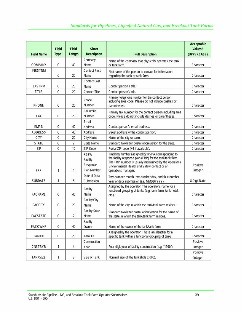
Standards for Pipelines, Liquefied Natural Gas, and Breakout Tank Farms
Standards for Pipeline, LNG, and Breakout Tank Farm Operator Submissions 39 U.S. DOT – 2004
Field Name Field Type1
Field Length
Short Description Full Description
Acceptable Values2
(UPPERCASE)
COMPANY C 40 Company Name
Name of the company that physically operates the tank or tank farm. Character
FIRSTNM C 20
Contact First Name
First name of the person to contact for information regarding the tank or tank farm. Character
LASTNM C 20 Contact Last Name Contact person’s title. Character
TITLE C 20 Contact Title Contact person’s title. Character
PHONE C 20 Phone Number
Primary telephone number for the contact person including area code. Please do not include dashes or parentheses. Character
FAX C 20 Facsimile Number
Primary fax number for the contact person including area code. Please do not include dashes or parentheses. Character
EMAIL C 40 Email Address Contact person’s email address. Character
ADDRESS C 40 Address Street address of the contact person. Character CITY C 20 City Name Name of the city or town. Character
STATE C 2 State Name Standard two-letter postal abbreviation for the state. Character ZIP C 10 ZIP Code Postal ZIP code (+4 if available). Character
FRP I 4
RSPA Facility Response Plan Number
Tracking number assigned by RSPA corresponding to the facility response plan (FRP) for the tank/tank farm. The FRP number is usually maintained by the operator’s Environmental Health and Safety contact or an operations manager.
Positive Integer
SUBDATE I 8 Date of Data Submission
Two-number month, two-number day, and four-number year of data submission (i.e. MMDDYYYY). 8-Digit Date
FACNAME C 40 Facility Name
Assigned by the operator. The operator’s name for a functional grouping of tanks (e.g. tank farm, tank hotel, etc.). Character
FACCITY C 20 Facility City Name Name of the city in which the tank/tank farm resides. Character
FACSTATE C 2 Facility State Name
Standard two-letter postal abbreviation for the name of the state in which the tank/tank farm resides. Character
FACOWNR C 40 Facility Owner Name of the owner of the tank/tank farm. Character
TANKID C 20 Tank ID Assigned by the operator. This is an identifier for a specific tank within a functional grouping of tanks. Character
CNSTRYR I 4 Construction Year Four-digit year of facility construction (e.g. “1990”).
Positive Integer
TANKSIZE I 3 Size of Tank Nominal size of the tank (bbls x 000). Positive Integer

Standards for Pipelines, Liquefied Natural Gas, and Breakout Tank Farms
Standards for Pipeline, LNG, and Breakout Tank Farm Operator Submissions 40 U.S. DOT – 2004
Field Name Field Type1
Field Length
Short Description Full Description
Acceptable Values2
(UPPERCASE)
CMDTY1 C 3
Primary Commodity Code
Abbreviation for the primary commodity stored in the tank. LNG= liquefied natural gas, CRD= crude oil, G= gasoline, K= kerosene, JF= jet fuel, DF= diesel fuel, HO= heating oil, AA= anhydrous ammonia, CO2= carbon dioxide, HVL= highly volatile liquid, OTH= other.
LNG, CRD, G, K, JF, DF, HO, AA, CO2, HVL, OTH
CMDTY2 C 3
Secondary Commodity Code
Abbreviation for the secondary commodity stored in the tank. LNG= liquefied natural gas, CRD= crude oil, G= gasoline, K= kerosene, JF= jet fuel, DF= diesel fuel, HO= heating oil, AA= anhydrous ammonia, CO2= carbon dioxide, HVL= highly volati le liquid, OTH= other.
LNG, CRD, G, K, JF, DF, HO, AA, CO2, HVL, OTH
CMDTY3 C 3
Tertiary Commodity Code
Abbreviation for the tertiary commodity stored in the tank. LNG= liquefied natural gas, CRD= crude oil, G= gasoline, K= kerosene, JF= jet fuel, DF= diesel fuel, HO= heating oil, AA= anhydrous ammonia, CO2= carbon dioxide, HVL= highly volatile liquid, OTH= other.
LNG, CRD, G, K, JF, DF, HO, AA, CO2, HVL, OTH
LONG_DIR C 1 Longitudinal Direction
The compass direction of the longitudinal coordinate (e.g. “N”). Character
LONGITUDE N 9 Longitudinal Coordinate
The longitudinal coordinate in decimal degree format (e.g. ###.######).
Number with 6 Decimal Places
LAT_DIR C 1 Latitudinal Direction
The compass direction of the latitudinal coordinate (e.g. “W”). Character
LATITUDE N 9 Latitudinal Coordinate
The latitudinal coordinate in decimal degree format (e.g. ###.######).
Number with 6 Decimal Places
SUB_TYPE C 1 Submission Type
Identifies this tank/tank farm as an A= addition to the NPMS, or D= deletion of a previous submission. A,M,D
Figure 7-1. Attribute field definitions for breakout tank features. Operators who maintain one breakout tank will submit the geographical location and attributes for the single tank. If an operator maintains multiple tanks at a given location, the submission will include a geographical location representing the approximate center of the tank farm and attributes for each breakout tank operated at the facility. Data input into either the Internet form or the executable file will conform to the database field types and definitions that are outlined in the attribute table . Operators will be required to provide answers to all questions in order to complete their submission. Figure 7-2 shows a flowchart of the submission process.

Standards for Pipelines, Liquefied Natural Gas, and Breakout Tank Farms
Standards for Pipeline, LNG, and Breakout Tank Farm Operator Submissions 41 U.S. DOT – 2004
Operator Submits Tank Farm and Individual Tank Data
Via Internet Application
• Geographic coordinates (latitude and longitude) of tank farm are submitted.
• Attributes for individual tanks in the tank farm are submitted.
• Data submissions accepted only if online form is complete.
• Identity of submitter verified for security and data integrity purposes.
Via Executable Application
• Geographic coordinates (latitude and longitude) of tank farm and individual tank attributes are entered into an executable program which generates a data submission that is mailed to the NPMS National Repository.
• Identity of submitter verified for security and data integrity purposes.
Submitted Information Converted to Geospatial Data for Use in a GIS
• The data will consist of points representing tank farms. • Attributes of the individual tanks in a tank farm will be stored as individual points with the same latitude and longitude coordinates as the tank farm.
Quality Control Procedures
Data Incorporated into OPS Database
• Submitted data overlaid on digital USGS 1:24,000 quads to verify location of tank farms. If USGS maps show tank farms corresponding to operator submissions, the data will be incorporated into OPS database.
• If the submitted data is not verified by USGS quads, OPS will generate a digital check-plot and email it to the operator for verification.
Figure 7-2. OPS tank farm and tank data collection process.

Standards for Pipelines, Liquefied Natural Gas, and Breakout Tank Farms
Standards for Pipeline, LNG, and Breakout Tank Farm Operator Submissions 42 U.S. DOT – 2004
All program related questions should be directed to Sam Hall ([email protected]; 202-493-0591) at OPS. If you have technical questions regarding the use of the online form or the executable file, we recommend you consult the Help system first. If the Help system does not answer your questions, please contact the National Repository at [email protected] or 703-317-6205.

Standards for Pipelines, Liquefied Natural Gas, and Breakout Tank Farms
Standards for Pipeline, LNG, and Breakout Tank Farm Operator Submissions 43 U.S. DOT – 2004
8. Submitting the Data Operators should use the following checklist to verify that the data being submitted to the NPMS Repository meets the standards and that all necessary information has been included. 8.1 Operator Submission Checklist 8.1.1 Attribute Data Submissions
ü Have all required fields in each feature attribute record been completed? ü Does each attribute record have a unique link to its line or point element in a geospatial file or
on the hard-copy map?
ü Has the attribute data been created and formatted according to the NPMS standard? ü Does each geospatial element have an attribute record?
8.1.2 Hard-Copy Geospatial Data Submissions
ü Are the maps USGS 1:24,000 topographic quadrangles or other NPMS-approved base maps? ü Have the maps been checked for scale and accuracy? ü Have the features been drafted on the map according to the NPMS standard?
ü Have the maps been edgematched? ü Are the features identified and clearly labeled on the map? ü Are the features distinguishable from each other on the map?
ü Does each map contain a legend and title identifying operator name and symbology used? 8.1.3 Digital Geospatial Data Submissions
ü Have the features been digitized according to the NPMS standard? ü Are the linear features continuous without gaps or overshoots?
ü Does each feature have a complete attribute record as defined in the NPMS standard? ü Has the attribute record been uniquely linked to the point or line feature? ü Has the submission file been exported and formatted according to the NPMS standard?
ü If the attribute data is in a separate file, has this file been exported according to the NPMS standard?
ü Have the data files being submitted on media been approved by the NPMS?
ü Are the submitted data file names descriptive and unique, following NPMS guidelines? ü Are all of the geospatial files included in this submission?
8.1.4. Operator Contact Information Submissions
ü Have you chosen either an individual or a general contact name as your contact, but not both? ü Have you filled in all required sections?
8.1.5 Metadata Submissions
ü Use the NPMS Metadata Template software.
ü Is the contact information current?

Standards for Pipelines, Liquefied Natural Gas, and Breakout Tank Farms
Standards for Pipeline, LNG, and Breakout Tank Farm Operator Submissions 44 U.S. DOT – 2004
ü Has the file name of the digital metadata file been entered into the attribute data records? ü Are the required sections of the metadata completed?
8.2 Packaging and Sending Data
1. Prepare a cover letter or transmittal form with contact information. Copy all digital file (s) including geospatial data, attribute data, and metadata to an NPMS-approved medium such as diskettes, CD-ROMs, or Iomega zip disks.
2. Roll hard copy maps and send in a tube. Do not send folded maps.
3. Mail submission to the NPMS National Repository.
If you have an all-digital submittal, you may transmit your data electronically. Connect to the NPMS National Repository Web site at www.npms.rspa.dot.gov for details.

Standards for Pipelines, Liquefied Natural Gas, and Breakout Tank Farms
Standards for Pipeline, LNG, and Breakout Tank Farm Operator Submissions A-1 U.S. DOT – 2003
Appendix 1 : Sample Hard-Copy Map and Attribute Data

Standards for Pipelines, Liquefied Natural Gas, and Breakout Tank Farms
Standards for Pipeline, LNG, and Breakout Tank Farm Operator Submissions A-2 U.S. DOT – 2003
A sample map is shown on the previous page. Provide digital attribute data for each pipeline and LNG facility. These attribute records relate to the hard-copy map.
Sample pipeline attribute data.
Sample LNG facility attribute data.

Standards for Pipelines, Liquefied Natural Gas, and Breakout Tank Farms
Standards for Pipeline, LNG, and Breakout Tank Farm Operator Submissions A-3 U.S. DOT – 2003
Appendix 2: Metadata Example for Geospatial Data Submissions The NPMS provides free software to help operators create metadata. Use of the software is required. Metadata allows users of NPMS data to understand the history and limitations of information with which they are working. NPMS metadata also serves as the transmittal form for providing essential information that repositories use to process the data. The NPMS Metadata Template creates a Microsoft Access .MDB file. Operators must send the .MDB file to a repository along with the rest of their NPMS submission. The 7-step template is similar to a hard-copy questionnaire. Operators should complete all required information on one screen before proceeding to the next screen. The application saves data automatically as it is entered. The name and location of the .MDB file to be created is established on the initial screen. Initial Screen. The initial screen requires the user to select the correct OPID. A list of valid operator names and OPIDs is provided. If unsure of your firm’s OPID, check with your accounting department. If you do not know what your OPID is, contact Shauna Turnbull at 202-366-3731. If your operator ID does not appear on the drop-down list, go to the Tools Menu and click on “Update OPID.” When the update is finished, try the drop-down list again. If your OPID still does not appear, contact National Repository staff at 703-317-6205. The initial metadata screen also allows the user to either edit an existing metadata file or to start a new file. If there is existing data for the operator you have selected and the submission is located in the current working directory, the default table for the chosen operator will appear in the “Browse” box. “Edit Existing Submission” will be the default choice. Data fields shown with a yellow background are required; while data fields shown with a white background are optional.

Standards for Pipelines, Liquefied Natural Gas, and Breakout Tank Farms
Standards for Pipeline, LNG, and Breakout Tank Farm Operator Submissions A-4 U.S. DOT – 2003
Step 1. Step 1 collects contact information. Submitting operators must provide name, mailing address, phone number, and, if available, e-mail address of a primary contact, and may provide information for a technical contact. The primary contact must be an employee of the operating company. The technical contact may be a technical employee or an outside contractor. If repository technicians have questions about a submission, they will contact the technical representative first, then the primary representative. The screen text will change from black to red when your cursor is on that field. Clicking on the “Next” button will advance the operator to Step 2.

Standards for Pipelines, Liquefied Natural Gas, and Breakout Tank Farms
Standards for Pipeline, LNG, and Breakout Tank Farm Operator Submissions A-5 U.S. DOT – 2003
Step 2. Step 2 asks questions about geospatial data quality, including positional accuracy. The appearance of subsequent screens will change depending on whether “hard-copy” or “digital” is selected in response to Question 2. Clicking on the “Next” button will advance the operator to Step 3.

Standards for Pipelines, Liquefied Natural Gas, and Breakout Tank Farms
Standards for Pipeline, LNG, and Breakout Tank Farm Operator Submissions A-6 U.S. DOT – 2003
Step 3. Step 3 continues questions from Step 2. Be sure to enter all required data. Clicking on the “Next” button will advance the operator to Step 4.

Standards for Pipelines, Liquefied Natural Gas, and Breakout Tank Farms
Standards for Pipeline, LNG, and Breakout Tank Farm Operator Submissions A-7 U.S. DOT – 2003
Step 4. Step 4 asks questions about attribute data quality. Attribute file names are also to be listed. The “Browse” feature allows you to select up to five files simultaneously. It automatically fills in the attribute file fields, listing them 1–5, and sends them to the metadata. Clicking on the “Next” button will advance the operator to Step 5.

Standards for Pipelines, Liquefied Natural Gas, and Breakout Tank Farms
Standards for Pipeline, LNG, and Breakout Tank Farm Operator Submissions A-8 U.S. DOT – 2003
Step 5. Step 5 collects information on the coordinate system of the submitted data. All submittals must be in real world coordinates. Several lists are provided to assist operators in providing complete and accurate coordinate information. If you cannot find an exact match for your coordinate system, use the space provided by question 18 to include details. Note that question 18 may be required or optional, depending on the projection you chose for your data. Clicking on the “Next” button will advance the operator to Step 6. If the drop-down lists do not provide a suitable response, you can key in an alternate entry.

Standards for Pipelines, Liquefied Natural Gas, and Breakout Tank Farms
Standards for Pipeline, LNG, and Breakout Tank Farm Operator Submissions A-9 U.S. DOT – 2003
Step 6. The content of Step 6 varies depending on whether “hard-copy” or “digital” data was chosen in Step 1 (Question 2). The operator will be presented with questions that relate directly to a hard-copy or a digital submission. Question 21 asks whether an operator is making a new submission, a partial replacement of data already in NPMS, or a full replacement.
Questions asked if submitting hard copy geospatial data.
Questions asked if submitting digital geospatial data.
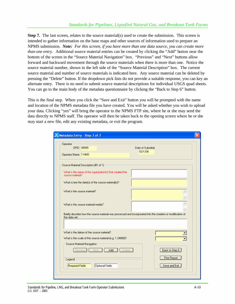
Standards for Pipelines, Liquefied Natural Gas, and Breakout Tank Farms
Standards for Pipeline, LNG, and Breakout Tank Farm Operator Submissions A-10 U.S. DOT – 2003
Step 7. The last screen, relates to the source material(s) used to create the submission. This screen is intended to gather information on the base maps and other sources of information used to prepare an NPMS submission. Note: For this screen, if you have more than one data source, you can create more than one entry. Additional source material entries can be created by clicking the “Add” button near the bottom of the screen in the “Source Material Navigation” box. “Previous” and “Next” buttons allow forward and backward movement through the source materials when there is more than one. Notice the source material number, shown in the left side of the “Source Material Description” box. The current source material and number of source materials is indicated here. Any source material can be deleted by pressing the “Delete” button. If the dropdown pick lists do not provide a suitable response, you can key an alternate entry. There is no need to submit source material descriptions for individual USGS quad sheets. You can go to the main body of the metadata questionnaire by clicking the “Back to Step 6” button. This is the final step. When you click the “Save and Exit” button you will be prompted with the name and location of the NPMS metadata file you have created. You will be asked whether you wish to upload your data. Clicking “yes” will bring the operator to the NPMS FTP site, where he or she may send the data directly to NPMS staff. The operator will then be taken back to the opening screen where he or she may start a new file, edit any existing metadata, or exit the program.

Standards for Pipelines, Liquefied Natural Gas, and Breakout Tank Farms
Standards for Pipeline, LNG, and Breakout Tank Farm Operator Submissions A-11 U.S. DOT – 2003
Appendix 3: Glossary A Abandoned pipeline ........ A pipeline that is no longer connected to the system and is no longer
maintained. The pipeline can be abandoned in place or by removal. Accuracy ........................ The degree of conformity with a recognized or established standard. Accuracy (absolute) ........ The accuracy of a map in representing the geographic location of an object
relative to its true location on the earth’s surface. Absolute accuracy is based on geographic coordinates.
Accuracy (relative) ......... The accuracy of a map in representing the geographic location of an object
relative to the locations of other objects. Alignment sheet .............. A general-purpose drawing designed to be used by company personnel
during the operation and maintenance of the pipeline. Alphanumeric ................. Consists of a possible combination of letters, numbers, and punctuation
symbols. Area ............................... A generic term for a bounded, continuous, two-dimensional object that may
or may not include its boundary. ASCII ............................ American Standard Code for Information Interchange. A popular standard
for the exchange of alphanumeric data. Attribute ........................ A characteristic that helps to describe the data.
B Base map ....................... A map containing visible surface features and boundaries that is used for
local reference. Breakout tank…………… A tank used to a) relieve surges in a hazardous liquid pipeline system or b)
receive and store hazardous liquid transported by a pipeline for reinjection and continued transportation.
C CAD or CADD ............... Computer Aided Drafting (CAD) and Design (CADD). An automated system
for the drafting and display of graphic oriented information. Control point .................. A point of known horizontal position used in digitizing paper maps. Conversion ..................... The process of transforming information from one form to another, e.g.,
analog (paper) data into digital data. Coordinates .................... Pairs of numbers expressing a known horizontal location on the earth’s
surface.
Standards for Pipelines, Liquefied Natural Gas, and Breakout Tank Farms
Standards for Pipeline, LNG, and Breakout Tank Farm Operator Submissions A-12 U.S. DOT – 2003
Crude oil ........................ Liquid petroleum out of the ground, as distinguished from refined oils
manufactured from crude oil.
D–E Database ........................ Structured collection of data defined for a particular use, user, system, or
program; may be sequential, network, hierarchical, relational, or semantic. Data capture ................... The process of converting hard-copy maps into a digital format. Data dictionary ............... A listing of each data field and a definition or description of what is
contained in that field. Data set .......................... A collection of related data. Datum (geodetic) ............ The level surface to which elevations are referenced, such as mean sea level.
A datum serves as a frame of reference for measuring a location on the surface of the earth.
Digital ............................ The discrete numerical representation of data. Digital centerline ............ A series of connected data elements representing the pipeline. Digital orthophotos ......... A digital image of an aerial photograph in which the displacement caused by
the camera tilt and by terrain has been corrected. Digitize .......................... The process of converting hard-copy manual drawings into digital format. DLG .............................. Digital Line Graphs. Digitized data from USGS base map categories,
including transportation, hydrology, elevation contours, and public land survey boundaries.
DXF .............................. Drawing eXchange Format. A graphic file and data interchange standard.
F Facilities ........................ Components of the pipeline system, such as the pipe, valves, and compressor
stations. FGDC ............................ Federal Geographic Data Committee. Established through OMB and charged
with coordinating the development, use, sharing, and dissemination of geographic data.
G Geodetic control ............. Surveying and monumental points on the earth’s surface whose location is
established in accordance with national standards.

Standards for Pipelines, Liquefied Natural Gas, and Breakout Tank Farms
Standards for Pipeline, LNG, and Breakout Tank Farm Operator Submissions A-13 U.S. DOT – 2003
Geographic ..................... Referring to coordinate systems, latitude/longitude or comparable geographic
grid location reference. Geospatial data ............... Information that identifies the geographic location and characteristics of
natural or constructed features and boundaries on the earth. GIS ................................ Geographic Information System. Computer hardware, software, and
geographic data used to capture, store, update, maintain, analyze, and display graphically referenced information.
GPS ............................... Global Positioning System. Survey instrument/process using satellite-
generated timing data to establish either ground or aerial coordinates. Graphic element ............. Points, lines, arcs, symbols, etc., which can be displayed.
H
Hardware ....................... The physical components of a computer system or network such as the
computer, printer, plotter, and terminal. Hazardous liquid ............. Petroleum, petroleum products, or anhydrous ammonia. Hazardous liquid trunkline ........................ A hazardous liquid transmission pipeline other than a flow line, gathering
line, or in-plant pipeline. Highly volatile liquid (HVL) ............................ A hazardous liquid that will form a vapor cloud when released to the
atmosphere and has a vapor pressure exceeding 276 kPa (40 psia) at 37.8° C (100° F). Note: natural gas liquids are also HVLs.

Standards for Pipelines, Liquefied Natural Gas, and Breakout Tank Farms
Standards for Pipeline, LNG, and Breakout Tank Farm Operator Submissions A-14 U.S. DOT – 2003
I–K In-service pipeline .......... A pipeline that transports natural gas or hazardous liquid, or is not currently
transporting products but is maintained and can be brought back into service. Interstate pipeline ........... A pipeline or part of a pipeline that is used in the transportation of natural
gas, hazardous liquid, or carbon dioxide in interstate or foreign commerce across state boundaries.
L Latitude ......................... Distance measured north or south of the equator. Liquefied Natural Gas (LNG) ............................ Natural gas or synthetic gas having methane as its major constituent that has
been changed to a liquid or semi solid. Liquefied Petroleum Gas (LPG) ...................... Butane and propane separated from natural gasoline and sold in liquid form
as fuel. Also known as bottled gas and tank gas. LNG facility .................... A pipeline facility that is used for 1) liquefying or solidifying natural gas, or
2) transferring, storing, or vaporizing liquefied natural gas. Longitude ....................... Distance measured east or west from the Prime Meridian in Greenwich,
England.
M Media ............................ The physical devices used to record, store, or transmit data, i.e. CD-ROM,
diskette, cartridge, tape. Metadata ........................ Descriptive information about data, such as the timeliness of the data,
attribute sources, and accuracy of the data. MQAT ........................... Joint Government-Industry Pipeline Mapping Quality Action Team.
Sponsored by OPS, API, and AGA/INGAA.
N NAD 27, 83 .................... North American Datum (of 1927 or 1983). Two mathematical
representations of the earth’s surface. Natural gas liquid ........... Also referred to as NGL. Can be ethane, butane, propane, or a propane-
butane mix. Natural gas transmission line ............. A pipeline system, other than a gathering line, that 1) Transports gas from a
gathering line or storage facility to a distribution center, storage facility, or

Standards for Pipelines, Liquefied Natural Gas, and Breakout Tank Farms
Standards for Pipeline, LNG, and Breakout Tank Farm Operator Submissions A-15 U.S. DOT – 2003
large-volume customer that is not downstream from a distribution center. A large-volume customer may receive similar volumes of gas as a distribution center, and includes factories, power plants, and institutional users of gas, 2) Operates at a hoop stress of 20 percent or more of specified minimum yield strength (SMYS), or 3) Transports gas within a storage field.
Nominal diameter ........... A dimensionless designator of pipe that indicates the standard pipe size.
O Offshore pipeline ............ A major natural gas transmission line or hazardous liquid trunkline on the
outer continental shelf that begins where production ends and transportation begins. For example, in state waters, a pipeline begins downstream of the outlet flange of each facility where either hydrocarbons are produced or where produced hydrocarbons are first separated, dehydrated, or otherwise processed – whichever facility is farther downstream.
One-Call ........................ Service to notify underground utilities of planned excavations. Operator ......................... A person or firm who operates a pipeline system and engages in the
transportation of gas or hazardous liquid. The operator may or may not also be the owner of the pipeline system.
Orthophoto ..................... Photo with camera tilt and relief displacements removed, resulting in a scale -
correct image. Overlay .......................... Simultaneously viewing two or more digital data sets of similar geographic
areas.
P Petroleum........................ Crude oil, condensate, natural gasoline, natural gas liquids, and liquefied
petroleum gas. Petroleum product ........... Flammable, toxic, or corrosive products obtained from distilling and
processing crude oil, unfinished oils, natural gas liquids, blend stocks, and other miscellaneous hydrocarbon compounds.
Pipeline corridor ............. A linear area where two or more pipelines (either part of the same or
different pipeline systems) are closely grouped in a single right-of-way. Pipeline corridors pose a cartographic challenge, and NPMS handles them differently on hard-copy and digital maps. On hard-copy maps, a single line with multiple annotations may represent pipeline corridors. In digital files, multiple lines are required, and operators should separate them into individual layers or files.
Pipeline crossing ............. A point where two or more pipelines cross, but where there is no physical
connection between the pipelines. Pipeline segments should not be broken at pipeline crossings.
Standards for Pipelines, Liquefied Natural Gas, and Breakout Tank Farms
Standards for Pipeline, LNG, and Breakout Tank Farm Operator Submissions A-16 U.S. DOT – 2003
Pipeline intersection ........ A point where a physical connection between two pipelines occurs. A commodity from one pipeline can flow into another pipeline(s), either a branch within a pipeline system or a connection between two pipeline systems.
Pipeline segment ............. A linear feature representing part or all of a pipeline system on a digital or
hard-copy map. A pipeline segment must have only two ends. No branches are allowed. A pipeline segment may be a straight line or may have any number of vertices. Each pipeline segment must be uniquely identified. The number of pipeline segments should be kept to the minimum needed to represent a pipeline system and its associated attributes. When submitting hard-copy maps, the beginning and ending points of each pipeline segment should be marked with a clear, visible dot. When submitting digital geospatial data, a unique line segment in the computer-aided drafting (CAD) or GIS data set should represent each pipeline segment.
Pipeline system ............... All parts of a major natural gas transmission line or hazardous liquid
trunkline though which gas or hazardous liquid is transported. By definition, only one firm can operate a pipeline system. Operators should assign unique names to each of their pipeline systems. A pipeline system may have an unlimited number of branches. Each pipeline system must be represented by one or more pipeline segments.
Q Quadrangles (Quads) ...... Typically refers to the USGS map sheets in the 7.5-minute quad series or the
15-minute quad series. Also known as topographic maps. Quality ........................... An essential or distinguishing characteristic needed for cartographic data to
be fit for use.
R Repository ...................... The entity designated to maintain, store, and warehouse NPMS data. Retired pipeline .............. A pipeline that is still connected to the system but has been taken out of
service and is no longer maintained. The operator plans to abandon the pipeline and is waiting for approval.
ROW ............................. Right-of-Way. A section of land designated for use by one or more pipelines.
The NPMS refers to ROWs as pipeline corridors.
S Scale (large) ................... Small map area showing greater detail, e.g., 1:2,400 = 1" to 200'. Scale (small) .................. Large map area with less detail, e.g., 1:100,000 = 1" to 8333'. Spatial data .................... Data about the location of objects and their relationship with one another.

Standards for Pipelines, Liquefied Natural Gas, and Breakout Tank Farms
Standards for Pipeline, LNG, and Breakout Tank Farm Operator Submissions A-17 U.S. DOT – 2003
T–Z Thematic ........................ The depiction of particular features or concepts. Topographic maps .......... Map showing horizontal and vertical contours, or lines of equal surface
elevation. Topography .................... Shape of configuration of the land surface. Represented by contour lines in
map form. Topology ....................... Description of the geographic relationship of features, especially features that
are adjacent to or connected to another feature. Vector ............................ Data composed of individual coordinate points and lines whose endpoints are
defined by coordinate pairs. .