Pioneering Geo-Support Solutions - Con-Tech Systems · Canada and the USA; from B.C. ... “Ground...
16
Strand Anchors Pioneering Geo-Support Solutions
Transcript of Pioneering Geo-Support Solutions - Con-Tech Systems · Canada and the USA; from B.C. ... “Ground...

S t r a n d A n c h o r sPioneering Geo-Support Solutions

Con-Tech Systems was found-ed in 1985 and is a family owned company. Since inception our primary focus in the initial stag-es was manufacturing post-ten-sioned Strand Anchors for geo-technical construction. Since that time, not only have we re-mained close to our roots with our innovative Strand products, but we have also developed and promoted many other unique and innovative products to al-low our customers to complete many difficult projects.
Con-Tech has completed strand projects as small as one anchor to projects containing thousands of anchors. We have completed projects with anchors as small as one strand, to ninety-two strands; still the largest anchor ever manufactured in the world. With these wide selections of products still available to our customers today we are abe to service not only large interna-
tional contractors but also small owner operators. We have the ability to produce anchors with standard corrosion protection systems and are also able to adapt to special project corro-sion requirements as needed. Through our several production plants and offices located across Canada and the USA; from B.C. to Ontario, from Washington State, to North Carolina and Florida, we are able to service any of your project needs.
... page 2
CTS ® S t r a n d A n c h o r s
Contents:
Company Introduction:
CoverCompany Profile...................................... Page 2Strand Anchor Introduction..................... Page 3Our Committment................................... Page 4Corrosion Protection Tree....................... Page 5Corrosion Protection Classification.... ..... Page 6Anchor Details......................................... Page 7Technical Data......................................... Page 8Technical Data......................................... Page 9Anchor Head Technical Data................... Page 10Hollow Ram Jacks................................... Page 11Accessories............................................. Page 12Accessories............................................. Page 13Strand Anchor Off-Coilers....................... Page 14Applications............................................ Page 15Back Cover: Contact Information
Pacific Coastal Highway Retaining Wall, Gorda, CA
The Dalles Dam, WA/OR
The Dalles Dam, WA/OR

... page 3
CTS ® S t r a n d A n c h o r s
CTS® Strand Anchors:
Advantages of CTS® Strand Anchors:
Recognised as one of the strongest, most flexible and cost effective anchor systems in the industry, Strand Anchors are in use throughout North America. Our unique encapsulation process ensures that the Strands’ bond length is not contaminated with the grease from the free length. Strand Anchors are typically used for either permanent or temporary tie down and tie back anchors in either rock or soil. Examples include hydroelectric dams, wind tower foundations, slope stabilization and excavation shoring.
Transportation of anchor tendons on reels coiled or looped. Therefore only small stor-age and assembly area are required.
Cutting of length of anchors on job site pos-sible to suit local ground conditions.
Installation of flexible anchor tendons un-der extremely tight space conditions.
Less danger of contact with overhead pow-er lines, because anchors are not as rigid as bars.
High yield point (1570 N/mm2 = 227 KSI) and low E-modulus of 20000 N/mm2 = 29000 KSI indicates that the strain of strand is greater than that for 150 KSI bars.
With our strand anchors more than one tension element in each anchor guarantees higher safety versus single bar anchors.
Our slim line strand coupler allows for easy splicing of even multiple strand anchors.
92 Strand Anchors, Seven Mile Dam. To date world’s largest anchors! Greenwich Wind Farm, Ontario, Canada

... page 4
Our Committment:Con-Tech Systems is committed to providing our customers with the best quality products and service. From the time an order is placed we have strict processes to ensure the customer gets not only what they need but also what they want. We have highly trained, professional staff who ensure that our anchors conform to the latest edition of the Post-Tensioning Institute Manual for Rock and Soil Anchors.
CTS ® S t r a n d A n c h o r s

... page 5
Corrosion Protection Tree:
Temporary(less than 2 years)
Service Life
Extended Temporary(2 to 5 years)
Permanent
Class I ProtectionAggressivityAggressivity
AggressiveAggressive Non-Aggressive Non-Aggressive
No ProtectionClass II Protection Class II ProtectionClass I Protection
CTS ® S t r a n d A n c h o r s

PROTECTION REQUIREMENTS Class Anchorage Unbonded Tendon Bond Length Length
PTI Class IEncapsulatedTendon
• Trumpet• Grout or corrosion
inhibiting com-pound filled, cover if exposed.
• Corrosion inhibiting compound filled sheath encased in grout, or
• Grout filled sheath, or• Grout encased epoxy-coat-
ed strand in a successfully water-pressure tested drill hole.
• No trumpet. • Grease-filled sheath.
• Grout-filled encapsula-tion, or
• Epoxy coated strand tendon in a successfully water-pressure tested drill hole.
• No extra protection required.
PTI Class II
Temporary - up to 24 months
• Grout encasement.• Corrosion inhibiting compound filled sheath encased in grout, or
• Grout filled sheath, or• Grout encased fully or
partially bonded tendon in sound rock or concrete.
• Trumpet• Grout or corrosion
inhibiting com-pound filled, cover if exposed.
... page 6
Corrosion Protection Classification:In the 2014 Recommendations for Prestressed Rock and Soil Anchors (this is the Fifth Edition and is endorsed by the ADSC Anchored Earth Retention Committee) the Post-Tensioning Institute defines three classes of Cor-rosion Protection:PTI Class I: Encapsulated Tendons (often referred to as double corrosion protected, DCP)PTI Class II: Grout Protected Tendons (often referred to as single corrosion protected, SCP)Temporary: Grout Protected (often referred to as single corrosion protected, SCP)
PTI Class I PTI Class II Temporary
TyPICAL APPLICATIONS:
CTS ® S t r a n d A n c h o r s

PTI - Class IDouble Corrosion Protection
PTI - Class II Single Corrosion Protection
Temporary AnchorNo Corrosion Protection
Cover CapWedge
Wedge Plate
Bearing Plate
Trumpet
Greased & Sheathed Strand in Unbonded Length
Organizers along Bond Length
Bare Strand in Bond Length
Centralizer
Unbonded Length
Bond Length
Pion
eerin
g G
eote
chni
cal S
olut
ions
Con-
Tech
Sys
tem
sWedge
Wedge Plate
Bearing Plate
Greased & Sheathed Strand in Unbonded Length
Organizers along Bond Length
Bare Strand in Bond Length
Centralizer
Cover Cap
Trumpet
Corrugated Sheathing
End Cap
Bond Length
Unbonded Length
Bond Length
Unbonded Length
Wedge
Wedge Plate
Bearing Plate
Organizers along Bond Length
Bare Strand in Bond Length
Centralizer
Seal Seal Seal
2’-0
” Sh
op
Grou
ted
Internal Grout Tube
Optional-Greased & Sheathed Strand in Unbonded Length
... page 7
Anchor Details:
Pion
eerin
g G
eote
chni
cal S
olut
ions
Con-
Tech
Sys
tem
s
Pion
eerin
g G
eote
chni
cal S
olut
ions
Con-
Tech
Sys
tem
s
CTS ® S t r a n d A n c h o r s
NominalDiameter
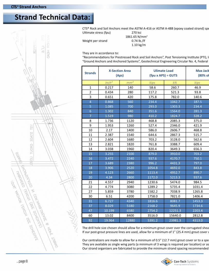
inch² mm² kips kN kips kN kips kN inch inch mm1 0.217 140 58.6 260.7 46.9 208.6 35.2 156.42 0.434 280 117.2 521.3 93.8 417.1 70.4 312.83 0.651 420 175.8 782.0 140.6 625.6 105.6 469.34 0.868 560 234.4 1042.7 187.5 834.1 140.8 625.75 1.085 700 293.0 1303.3 234.4 1042.7 176.0 782.16 1.302 840 351.6 1564.0 281.3 1251.2 211.2 938.57 1.519 980 410.2 1824.7 328.2 1459.7 246.4 1094.98 1.736 1120 468.8 2085.3 375.0 1668.3 281.6 1251.49 1.953 1260 527.4 2346.0 421.9 1876.8 316.8 1407.810 2.17 1400 586.0 2606.7 468.8 2085.3 352.0 1564.211 2.387 1540 644.6 2867.3 515.7 2293.9 387.2 1720.612 2.604 1680 703.2 3128.0 562.6 2502.4 422.4 1877.013 2.821 1820 761.8 3388.7 609.4 2710.9 457.6 2033.514 3.038 1960 820.4 3649.3 656.3 2919.5 492.8 2189.915 3.255 2100 879.0 3910.0 703.2 3128.0 528.0 2346.316 3.472 2240 937.6 4170.7 750.1 3336.5 563.2 2502.717 3.689 2380 996.2 4431.3 797.0 3545.1 598.4 2659.118 3.906 2520 1054.8 4692.0 843.8 3753.6 633.6 2815.619 4.123 2660 1113.4 4952.7 890.7 3962.1 668.8 2972.020 4.34 2800 1172.0 5213.3 937.6 4170.7 703.2 3128.021 4.557 2940 1230.6 5474.0 984.5 4379.2 738.4 3284.422 4.774 3080 1289.2 5735.4 1031.4 4588.3 773.5 3441.227 5.859 3780 1582.2 7038.9 1265.8 5631.1 949.3 4223.330 6.51 4200 1758.0 7821.0 1406.4 6256.8 1054.8 4692.631 6.727 4340 1816.6 8081.7 1453.3 6465.4 1090.0 4849.037 8.029 5180 2168.2 9645.9 1734.6 7716.7 1300.9 5787.547 10.199 6580 2754.2 12251.3 2203.4 9801.0 1654.4 7351.760 13.02 8400 3516.0 15640.0 2812.8 12512.0 2112.0 9385.2 10" 11.6 29592 19.964 12880 5391.2 23981.3 4313.0 19185.0 3238.4 14390.6 N/A N/A N/A
2" 2.4 61
Max Jacking Load (80% of GUTS)
3" 3.6
8" 9.5
91
241
6" 7.1 180
Strands
5" 5.7 145
4" 4.7 119
HDPE Corrugated Sheathing
Outside Diameter
Max Design Load (60% of GUTS)
Ulimate Load (fpu x APS) = GUTS
X-Section Area(Aps)
The drill hole size chosen should allow for a minimum grout cover over the corrugated sheath of 0.5” (12.7 mm).If our post-grout pressure lines are used, allow for a minimum of 1” (25.4 mm) grout cover on the side where the grout pipe is assembled.
Our centralizers are made to allow for a minimum of 0.5” (12.7 mm) grout cover or to a specified size.They are available as single wing parts (a minimum of 3 wings is required per location) or as multiple wing elements.Our strand organizers are fabricated to provide the minimum strand spacing recommended in the PTI manual.
CTS® Rock and Soil Anchors meet the ASTM A-416 or ASTM A-488 (epoxy coated strand) specifications for 0.6”, 7 wire strand.Ultimate stress (fpu) 270 ksi 1861.65 N/mm2
Weight per strand 0.74 lb./lf 1.10 kg/m
They are in accordance to:“Recommendations for Prestressed Rock and Soil Anchors”, Post Tensioning Institute (PTI), latest edition.“Ground Anchors and Anchored Systems”, Geotechnical Engineering Circular No. 4, Federal Highway Administration, Washington DC, FHWA-IF-99-015, 1999
... page 8
Strand Technical Data:CTS ® S t r a n d A n c h o r s

NominalDiameter
inch² mm² kips kN kips kN kips kN inch inch mm1 0.217 140 58.6 260.7 46.9 208.6 35.2 156.42 0.434 280 117.2 521.3 93.8 417.1 70.4 312.83 0.651 420 175.8 782.0 140.6 625.6 105.6 469.34 0.868 560 234.4 1042.7 187.5 834.1 140.8 625.75 1.085 700 293.0 1303.3 234.4 1042.7 176.0 782.16 1.302 840 351.6 1564.0 281.3 1251.2 211.2 938.57 1.519 980 410.2 1824.7 328.2 1459.7 246.4 1094.98 1.736 1120 468.8 2085.3 375.0 1668.3 281.6 1251.49 1.953 1260 527.4 2346.0 421.9 1876.8 316.8 1407.810 2.17 1400 586.0 2606.7 468.8 2085.3 352.0 1564.211 2.387 1540 644.6 2867.3 515.7 2293.9 387.2 1720.612 2.604 1680 703.2 3128.0 562.6 2502.4 422.4 1877.013 2.821 1820 761.8 3388.7 609.4 2710.9 457.6 2033.514 3.038 1960 820.4 3649.3 656.3 2919.5 492.8 2189.915 3.255 2100 879.0 3910.0 703.2 3128.0 528.0 2346.316 3.472 2240 937.6 4170.7 750.1 3336.5 563.2 2502.717 3.689 2380 996.2 4431.3 797.0 3545.1 598.4 2659.118 3.906 2520 1054.8 4692.0 843.8 3753.6 633.6 2815.619 4.123 2660 1113.4 4952.7 890.7 3962.1 668.8 2972.020 4.34 2800 1172.0 5213.3 937.6 4170.7 703.2 3128.021 4.557 2940 1230.6 5474.0 984.5 4379.2 738.4 3284.422 4.774 3080 1289.2 5735.4 1031.4 4588.3 773.5 3441.227 5.859 3780 1582.2 7038.9 1265.8 5631.1 949.3 4223.330 6.51 4200 1758.0 7821.0 1406.4 6256.8 1054.8 4692.631 6.727 4340 1816.6 8081.7 1453.3 6465.4 1090.0 4849.037 8.029 5180 2168.2 9645.9 1734.6 7716.7 1300.9 5787.547 10.199 6580 2754.2 12251.3 2203.4 9801.0 1654.4 7351.760 13.02 8400 3516.0 15640.0 2812.8 12512.0 2112.0 9385.2 10" 11.6 29592 19.964 12880 5391.2 23981.3 4313.0 19185.0 3238.4 14390.6 N/A N/A N/A
2" 2.4 61
Max Jacking Load (80% of GUTS)
3" 3.6
8" 9.5
91
241
6" 7.1 180
Strands
5" 5.7 145
4" 4.7 119
HDPE Corrugated Sheathing
Outside Diameter
Max Design Load (60% of GUTS)
Ulimate Load (fpu x APS) = GUTS
X-Section Area(Aps)
The drill hole size chosen should allow for a minimum grout cover over the corrugated sheath of 0.5” (12.7 mm).If our post-grout pressure lines are used, allow for a minimum of 1” (25.4 mm) grout cover on the side where the grout pipe is assembled.
Our centralizers are made to allow for a minimum of 0.5” (12.7 mm) grout cover or to a specified size.They are available as single wing parts (a minimum of 3 wings is required per location) or as multiple wing elements.Our strand organizers are fabricated to provide the minimum strand spacing recommended in the PTI manual.
CTS® Rock and Soil Anchors meet the ASTM A-416 or ASTM A-488 (epoxy coated strand) specifications for 0.6”, 7 wire strand.Ultimate stress (fpu) 270 ksi 1861.65 N/mm2
Weight per strand 0.74 lb./lf 1.10 kg/m
They are in accordance to:“Recommendations for Prestressed Rock and Soil Anchors”, Post Tensioning Institute (PTI), latest edition.“Ground Anchors and Anchored Systems”, Geotechnical Engineering Circular No. 4, Federal Highway Administration, Washington DC, FHWA-IF-99-015, 1999
... page 9
CTS ® S t r a n d A n c h o r s
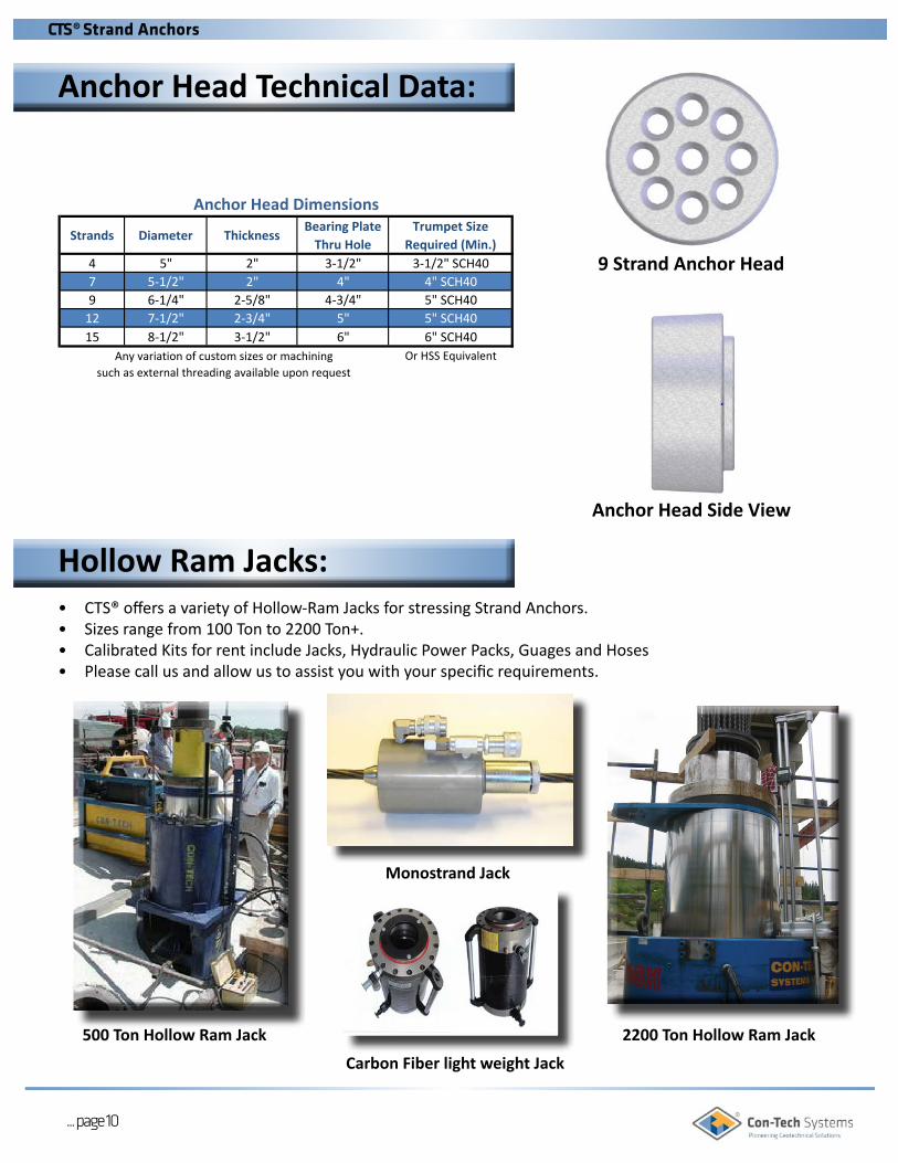
• CTS® offers a variety of Hollow-Ram Jacks for stressing Strand Anchors.• Sizes range from 100 Ton to 2200 Ton+.• Calibrated Kits for rent include Jacks, Hydraulic Power Packs, Guages and Hoses• Please call us and allow us to assist you with your specific requirements.
Hollow Ram Jacks:
Strands Diameter ThicknessBearing Plate
Thru HoleTrumpet Size
Required (Min.)4 5" 2" 3-1/2" 3-1/2" SCH407 5-1/2" 2" 4" 4" SCH409 6-1/4" 2-5/8" 4-3/4" 5" SCH40
12 7-1/2" 2-3/4" 5" 5" SCH4015 8-1/2" 3-1/2" 6" 6" SCH40
Or HSS Equivalent
Anchor Head Dimensions
Any variation of custom sizes or machining such as external threading available upon request
2200 Ton Hollow Ram Jack500 Ton Hollow Ram Jack
Monostrand Jack
Carbon Fiber light weight Jack
... page 10
Anchor Head Technical Data:
9 Strand Anchor Head
Anchor Head Side View
CTS ® S t r a n d A n c h o r s

Stressing Jacks table:
ModelNumber
Usage(No. of Strands)
StrokeRam Area
(inch2)
Maximum Load
@ 10,000 PSI
CenterHole I.D.
CylinderO.D.
HeightCollapsed
MaterialWeight
(lbs.)
CTS-CBJ-3 1 3.0 " 5.0 " 25 TONS 0.70 " 4.25 " 8.00 " ALUM 10CTS-25-8 1 8.0 " 5.0 " 25 TONS 0.70 " 4.50 " 13.00 " ALUM 20CTS-50 Titan 4.0 " 10.3 " 50 TONS 2.12 " 7.50 " 9.50 " ALUM 40
CTS-100 4 6.0 " 21.0 " 100 TONS 2.00 " 7.00 " 12.50 " STEEL 90CTS-100 4 8.0 " 21.0 " 100 TONS 3.50 " 10.00 " 16.00 " ALUM 120CTS-120 5 6.5 " 24.3 " 120 TONS 3.50 " 9.50 " 14.00 " ALUM 80CTS-150 6 8.0 " 30.0 " 150 TONS 3.50 " 10.00 " 15.00 " ALUM 125CTS-150 6 10.0 " 29.5 " 150 TONS 3.50 " 12.00 " 19.00 " ALUM 225CTS-200 7 7.0 " 40.0 " 200 TONS 3.50 " 11.00 " 17.00 " STEEL 335CTS-200 7 9.5 " 40.0 " 200 TONS 3.50 " 12.00 " 19.00 " ALUM 200CTS-200 9 9.5 " 40.0 " 200 TONS 4.50 " 11.50 " 21.00 " STEEL 450CTS-300 12 18.0 " 60.0 " 300 TONS 5.25 " 14.00 " 27.50 " STEEL 875CTS-300 12 18.0 " 60.0 " 300 TONS 5.25 " 14.00 " 34.00 " STEEL 1,350CTS-500 15 14.0 " 110.0 " 500 TONS 8.00 " 20.00 " 27.50 " STEEL 1,830CTS-800 27 14.0 " 160.0 " 800 TONS 9.50 " 26.50 " 32.50 " STEEL 3,600
CTS-2200 92 35.0 " 440.0 " 2,200 TONS 16.00 " 38.50 " 55.00 " STEEL 13,000
... page 11
Hollow Ram Jack Details:
CTS ® S t r a n d A n c h o r s

Restrainer Plates - Standard restraining plates are kept in stock in the 4, 7, 9, 12, and 15 strand sizes however, any other size can be fabricated to match the required anchor.
Adjustable Stressing Chairs - available in 4, 7, 9, 12 and 15 Strand sizes.
Anchor Heads - Many standard sizes available as well as any custom anchor head if required.
Organizers - Can be made to accommodate any size of anchor.
... page 12
Accessories:
CTS ® S t r a n d A n c h o r s

Grippers - Designed to be used with standard .600” 7 wire strand anchor tendon. Variety of sizes are available.
Cover Caps - Standard sizes stocked for 4, 7, 9, 12, and 15 strand anchor heads. Custom sizes are available.
Post Grout Tubes - any required length can be accommodated thanks to our modular system.
Couplers - designed to be used with standard 0.600” diameter, 7 wire anchor tendon.
Bearing Plates - any size or configuration can be ac-commodated including addition of trumpets if needed.
Centralizers - Various sizes and styles including balloon, snap ring, banana peel style, and heavy duty.
... page 13
Accessories:
CTS ® S t r a n d A n c h o r s

... page 14
Strand Anchor Off-Coilers:
Manually operated Horizontal Off-Coiler
Con-Tech Systems offers uncoiling equipment to facilitate the safe installation of our Strand Anchors. Manual Horizontal and Motorized Vertical Off-Coilers are available for a variety of applications.
Motorized Vertical Off-Coiler
Manually operated Horizontal Off-Coiler
... page 14
CTS ® S t r a n d A n c h o r s

... page 15... page 15
Applications:
Dam Retrofits Tom Miller Dam, Austin TX
Excavation Shoring The Cosmopolitan, Las Vegas NV
Bridges Bixby Creek Bridge, CA
Retaining Walls US 27/SR 29 Hwy, Chatanooga, TN
Foundations Greenwich Wind Farm, Ontario
Landslide Mitigation The Point, San Diego, CA
CTS ® S t r a n d A n c h o r s

Version: December 2014
Memberships:Partnerships:
Website: www.contechsystems.com
Magnolia Point, Seattle WATie Back Anchors for mud slide repair. (In progress & completion)
Seven Mile Dam, B.C.Seismic upgrade of the hydro power dam.
CTS Tie Down Anchors with 92 Strands.
Head Office: Sales & Production:• 8150 River Road, Delta, B.C., Canada, V4G 1B5 Tel: 604-946-5571
Toll Free: 1-888-818-4826Email: [email protected]
Eastern Locations: Sales & Production: • Brockville, ON, Canada
Tel: 613-342-0041• Charlotte, NC, USA
Tel: 704-494-3989Sales: • Bushkill, PA, USA
Tel: 570-807-9617• New Port Richey, FL, USA
Tel: 727-842-5760Email: [email protected]
Western Locations: Sales & Production Plant:• 3736 South Tacoma Way, Tacoma, WA, 98409, USA Tel: 253-237-9008
Toll Free: 1-888-818-4826Email: [email protected]