Pinball Machine ECE Capstone Project · Abstract: The goal of our project was to design, construct...
48
Pinball Machine ECE Capstone Project May 1 st 2013 Dan Nolte Noah Silow-Carroll
Transcript of Pinball Machine ECE Capstone Project · Abstract: The goal of our project was to design, construct...
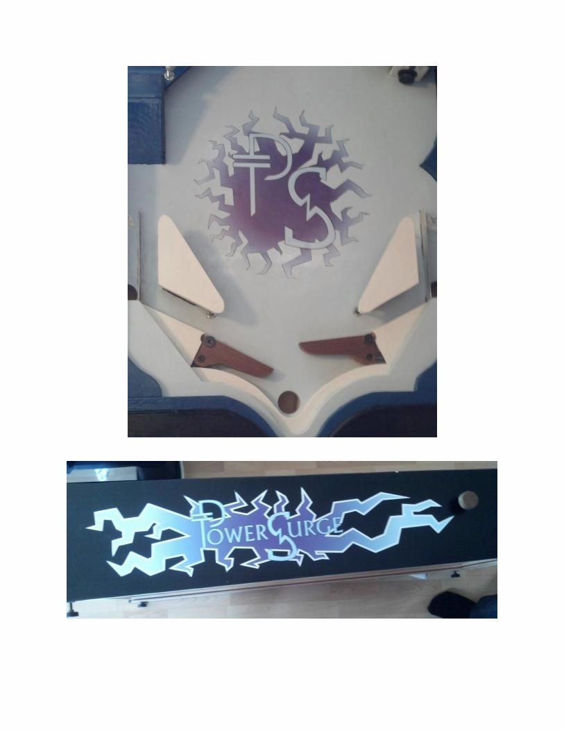
Pinball Machine
ECE Capstone Project
May 1st 2013
Dan Nolte Noah Silow-Carroll
Abstract:
The goal of our project was to design, construct and implement a pinball state machine using a
wide range of electrical and computer engineering concepts. This project involved the use of many core
concepts of Principles of Electrical Engineering I and II, digital logic design, electronic devices, digital
electronics, digital system design and programming methodology I and II as well as many of the
accompanying labs. The machine was achieved using an arduino programmable logic device, an array of
different sensors, and a series of LED circuits.
Summary of construction process:
The initial stages of the construction process consisted of sketching a design for the deck
(playing surface). This process involved several iterations. Once a design was settled upon, and adequate
sensors were ordered, it was time to begin the physical construction of the machine. One of the initial
concerns was the flipper mechanism. It was unclear how we could effectively translate the lateral
motion of a pushed button embedded on the side of the machine into rotational motion smoothly
enough to operate a flipper without significant losses to friction.
A prototype was constructed to test one of the better theories that we came up with. We knew
that the rough dimensions of the deck would be two feet wide and four feet long. We had not yet
settled on the pitch of the deck, assuming that this would be best decided by the power that we could
get out of the flippers, as they needed to be able to propel the ball close to four feet uphill, and then up
an even steeper ramp at the head of the deck.
Flipper construction:
The concerns with creating a flipper were that it needed to be strong enough to throw a one
inch steel ball bearing four feet up an incline, without requiring excessive force from the player to
operate them. We will consider the right-hand flipper in this analysis. The concept in this design was to
construct a button on the outside of the machine with roughly an inch of motion. This one inch of lateral
motion had to be translated into a rotation of the flipper to an extension of roughly 60 degrees from its
resting position, and then the flipper must return to the resting position of its own power. This meant
that we could either use a heavy flipper, and allow gravity to pull it back into place, or include a spring in
the design. We felt that, with the shallow pitch of the deck, a flipper would need to be very heavy to fall
back to the resting position via gravity, and the rotation mechanism would have to be exceedingly
smooth. But the additional weight of the flipper leads to additional strain on the player. Taking a
random guess at the number of times that a player would operate the flipper on one full game to be
around 200, we decided that ease of operation should be a larger concern. So we moved to a design
involving a spring. The majority of the mechanism consists of a length of 1/4" threaded steel rod. This is
screwed into a threaded cross dowel. This was the key to the movement of the flipper. The cross dowel,
or cross nut, is a cylindrical piece of steel that has a threaded hole drilled through the side. This cylinder
was inserted vertically into the lower right corner of the flipper itself. The drilled hole would face to the
right, in this situation. Then a lateral opening is cut in the right side of the flipper, and the threaded steel
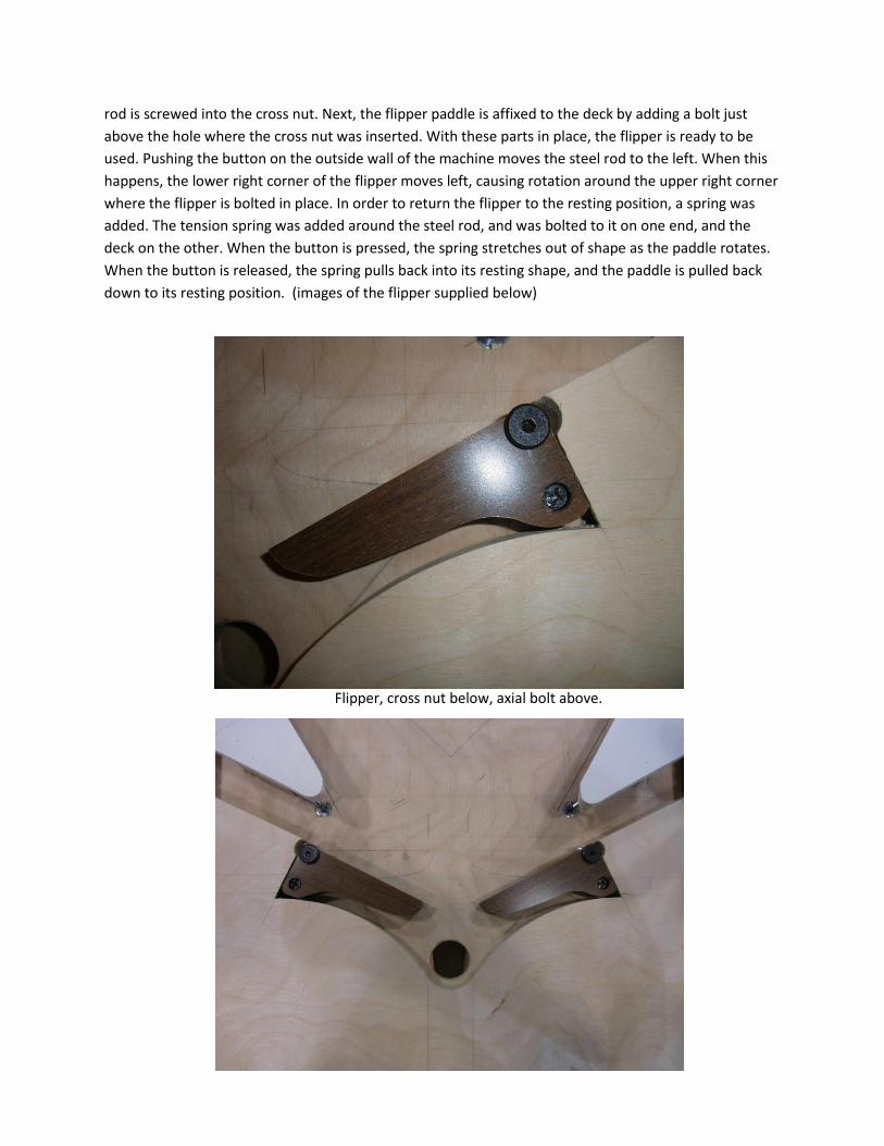
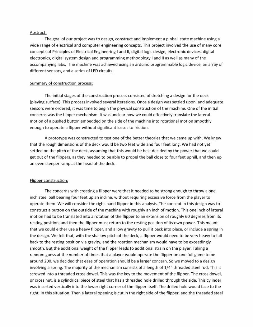
rod is screwed into the cross nut. Next, the flipper paddle is affixed to the deck by adding a bolt just
above the hole where the cross nut was inserted. With these parts in place, the flipper is ready to be
used. Pushing the button on the outside wall of the machine moves the steel rod to the left. When this
happens, the lower right corner of the flipper moves left, causing rotation around the upper right corner
where the flipper is bolted in place. In order to return the flipper to the resting position, a spring was
added. The tension spring was added around the steel rod, and was bolted to it on one end, and the
deck on the other. When the button is pressed, the spring stretches out of shape as the paddle rotates.
When the button is released, the spring pulls back into its resting shape, and the paddle is pulled back
down to its resting position. (images of the flipper supplied below)
Flipper, cross nut below, axial bolt above.
Infrared Sensor:
The first type of sensor used infrared light. The sensor consisted of an IR emitter, and an IR
detector. The emitter works just as any LED circuit. The detector is a more interesting circuit. In the
presence of the correct wavelength of IR light, the detector acts as a short circuit. When the light source
is blocked, the detector becomes an open circuit. The resulting schematic works as a voltage divider. The
arduino senses the voltage just before the detector. To utilize this sensor in the game, there needed to
be a mechanism that would block the light from the emitter in the presence of a pinball. Ideally, this
would be achieved by rolling the ball between the emitter and detector. However, the detector can be
sensitive to ambient lighting. Additionally, the ball itself is polished steel, and being spherical, could not
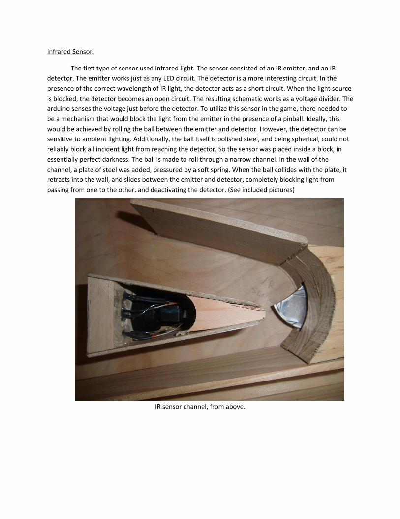
reliably block all incident light from reaching the detector. So the sensor was placed inside a block, in
essentially perfect darkness. The ball is made to roll through a narrow channel. In the wall of the
channel, a plate of steel was added, pressured by a soft spring. When the ball collides with the plate, it
retracts into the wall, and slides between the emitter and detector, completely blocking light from
passing from one to the other, and deactivating the detector. (See included pictures)
IR sensor channel, from above.
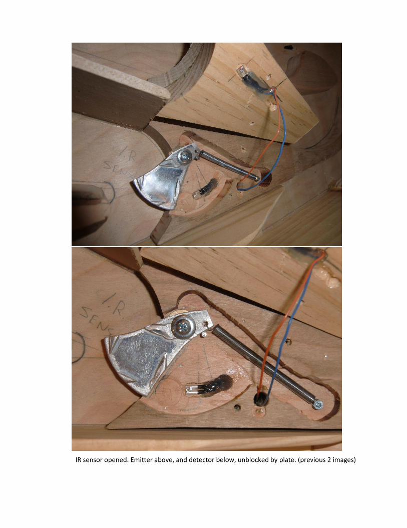
IR sensor opened. Emitter above, and detector below, unblocked by plate. (previous 2 images)
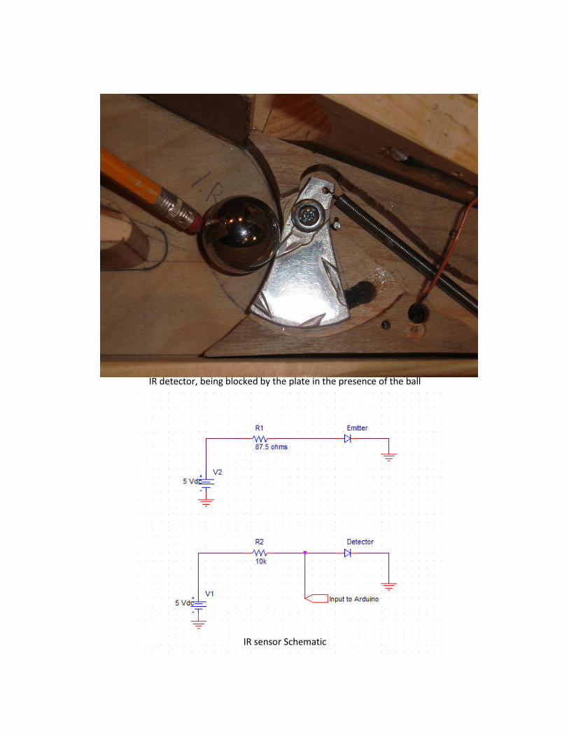
IR detector, being blocked by the plate in the presence of the ball
IR sensor Schematic
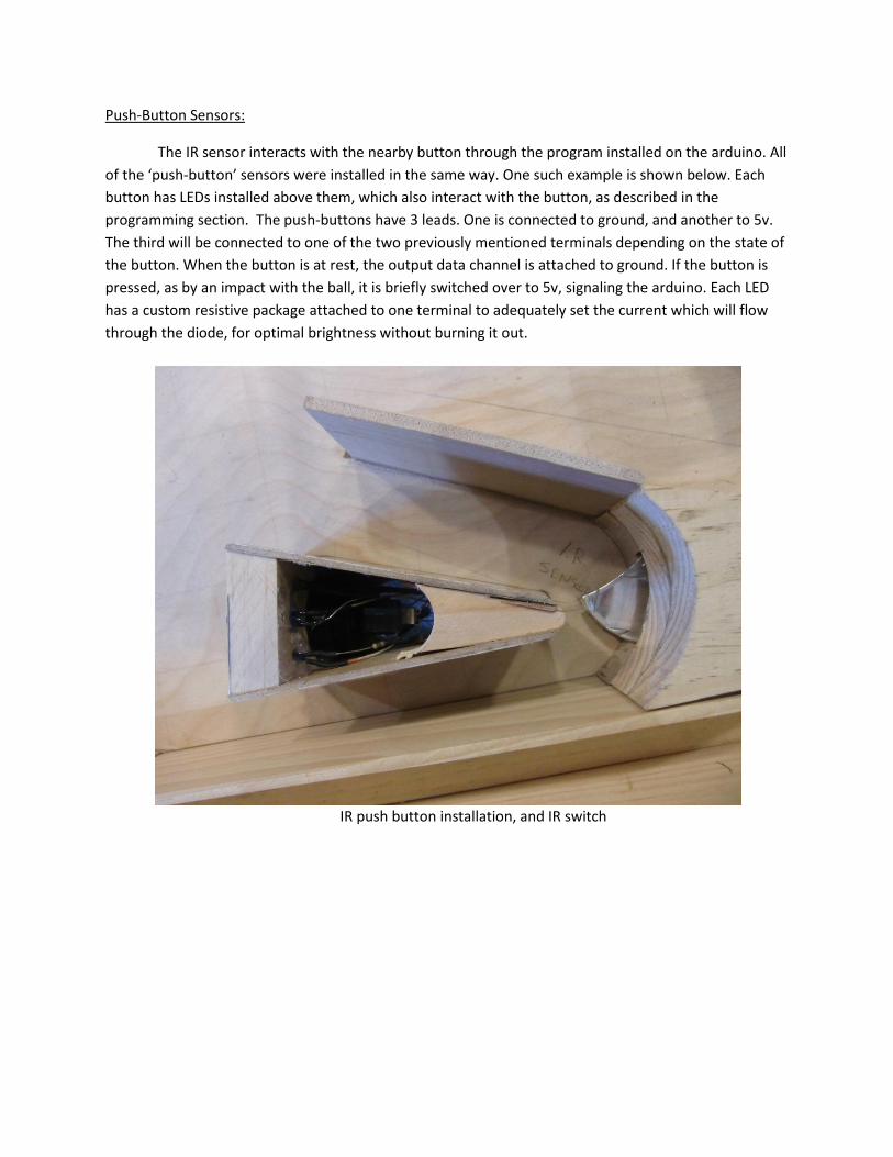
Push-Button Sensors:
The IR sensor interacts with the nearby button through the program installed on the arduino. All
of the ‘push-button’ sensors were installed in the same way. One such example is shown below. Each
button has LEDs installed above them, which also interact with the button, as described in the
programming section. The push-buttons have 3 leads. One is connected to ground, and another to 5v.
The third will be connected to one of the two previously mentioned terminals depending on the state of
the button. When the button is at rest, the output data channel is attached to ground. If the button is
pressed, as by an impact with the ball, it is briefly switched over to 5v, signaling the arduino. Each LED
has a custom resistive package attached to one terminal to adequately set the current which will flow
through the diode, for optimal brightness without burning it out.
IR push button installation, and IR switch
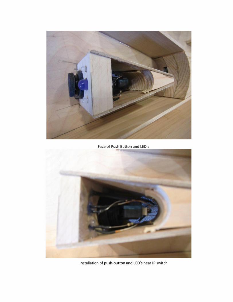
Face of Push Button and LED’s
Installation of push-button and LED’s near IR switch
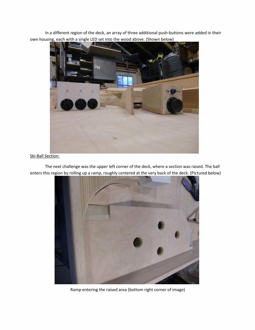
In a different region of the deck, an array of three additional push-buttons were added in their
own housing, each with a single LED set into the wood above. (Shown below)
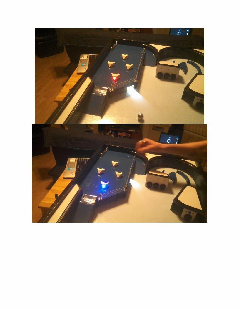
Ski-Ball Section:
The next challenge was the upper left corner of the deck, where a section was raised. The ball
enters this region by rolling up a ramp, roughly centered at the very back of the deck. (Pictured below)
Ramp entering the raised area (bottom right corner of image)
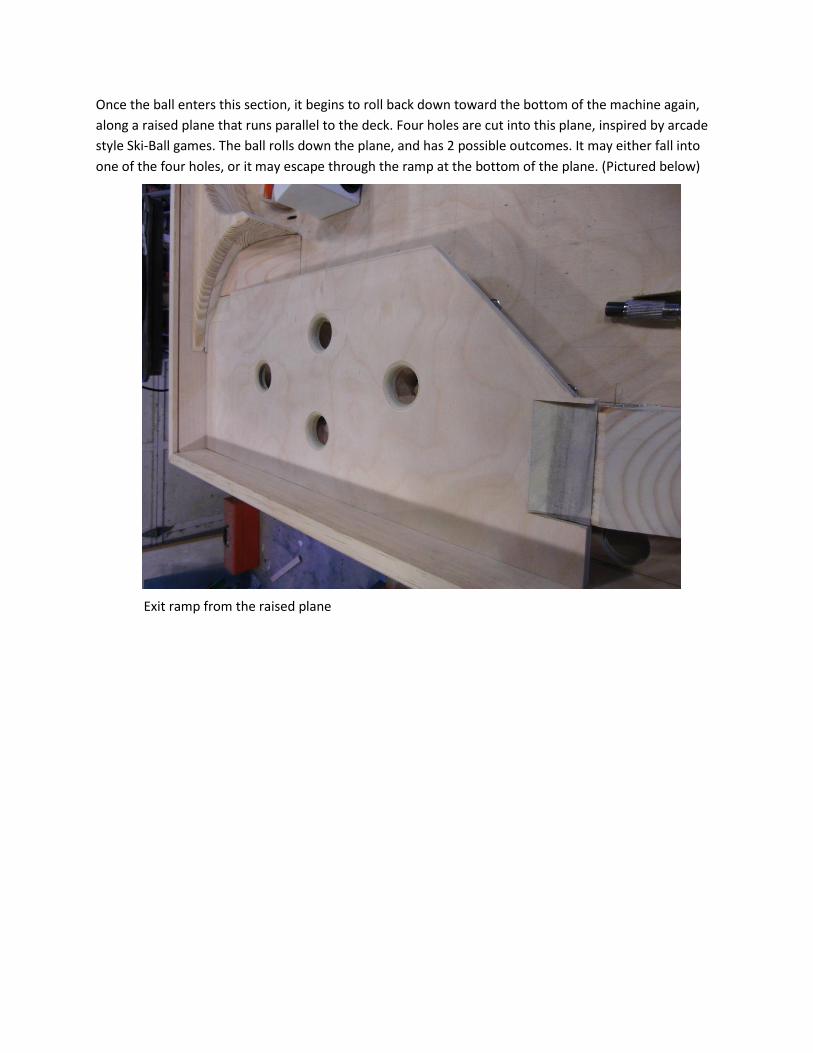
Once the ball enters this section, it begins to roll back down toward the bottom of the machine again,
along a raised plane that runs parallel to the deck. Four holes are cut into this plane, inspired by arcade
style Ski-Ball games. The ball rolls down the plane, and has 2 possible outcomes. It may either fall into
one of the four holes, or it may escape through the ramp at the bottom of the plane. (Pictured below)
Exit ramp from the raised plane
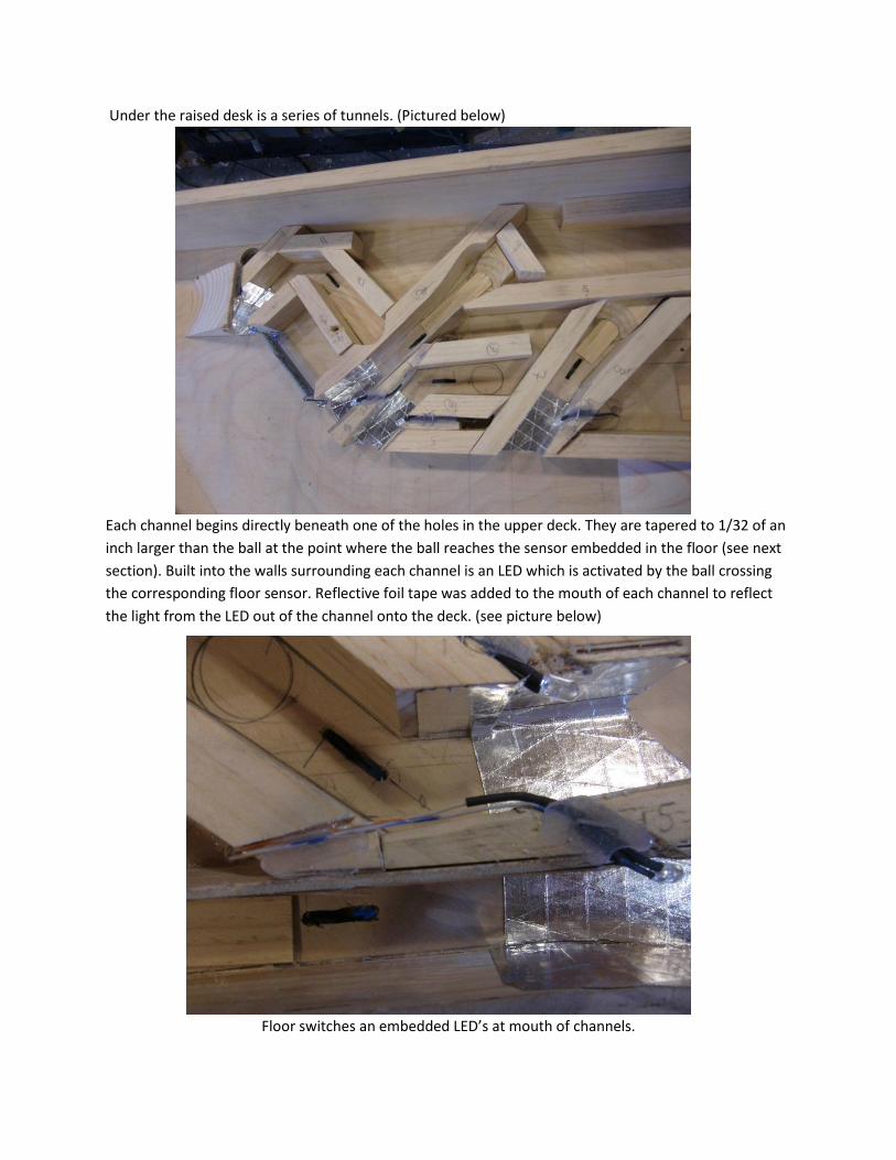
Under the raised desk is a series of tunnels. (Pictured below)
Each channel begins directly beneath one of the holes in the upper deck. They are tapered to 1/32 of an
inch larger than the ball at the point where the ball reaches the sensor embedded in the floor (see next
section). Built into the walls surrounding each channel is an LED which is activated by the ball crossing
the corresponding floor sensor. Reflective foil tape was added to the mouth of each channel to reflect
the light from the LED out of the channel onto the deck. (see picture below)
Floor switches an embedded LED’s at mouth of channels.
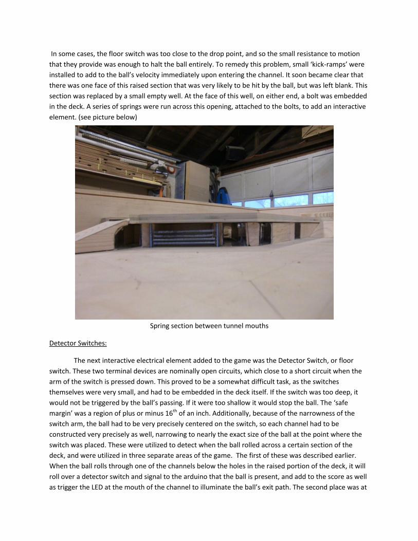
In some cases, the floor switch was too close to the drop point, and so the small resistance to motion
that they provide was enough to halt the ball entirely. To remedy this problem, small ‘kick-ramps’ were
installed to add to the ball’s velocity immediately upon entering the channel. It soon became clear that
there was one face of this raised section that was very likely to be hit by the ball, but was left blank. This
section was replaced by a small empty well. At the face of this well, on either end, a bolt was embedded
in the deck. A series of springs were run across this opening, attached to the bolts, to add an interactive
element. (see picture below)
Spring section between tunnel mouths
Detector Switches:
The next interactive electrical element added to the game was the Detector Switch, or floor
switch. These two terminal devices are nominally open circuits, which close to a short circuit when the
arm of the switch is pressed down. This proved to be a somewhat difficult task, as the switches
themselves were very small, and had to be embedded in the deck itself. If the switch was too deep, it
would not be triggered by the ball’s passing. If it were too shallow it would stop the ball. The ‘safe
margin’ was a region of plus or minus 16th of an inch. Additionally, because of the narrowness of the
switch arm, the ball had to be very precisely centered on the switch, so each channel had to be
constructed very precisely as well, narrowing to nearly the exact size of the ball at the point where the
switch was placed. These were utilized to detect when the ball rolled across a certain section of the
deck, and were utilized in three separate areas of the game. The first of these was described earlier.
When the ball rolls through one of the channels below the holes in the raised portion of the deck, it will
roll over a detector switch and signal to the arduino that the ball is present, and add to the score as well
as trigger the LED at the mouth of the channel to illuminate the ball’s exit path. The second place was at
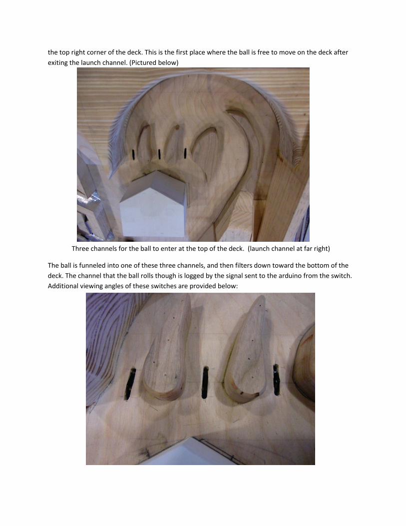
the top right corner of the deck. This is the first place where the ball is free to move on the deck after
exiting the launch channel. (Pictured below)
Three channels for the ball to enter at the top of the deck. (launch channel at far right)
The ball is funneled into one of these three channels, and then filters down toward the bottom of the
deck. The channel that the ball rolls though is logged by the signal sent to the arduino from the switch.
Additional viewing angles of these switches are provided below:
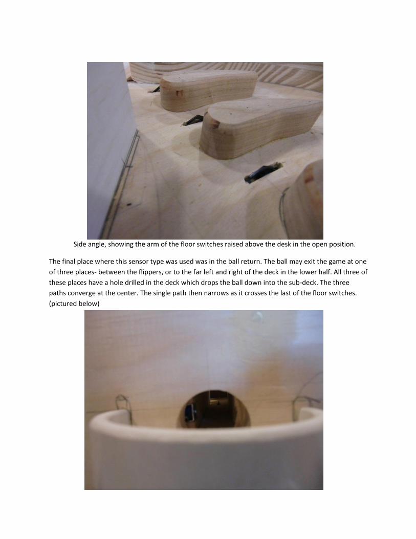
Side angle, showing the arm of the floor switches raised above the desk in the open position.
The final place where this sensor type was used was in the ball return. The ball may exit the game at one
of three places- between the flippers, or to the far left and right of the deck in the lower half. All three of
these places have a hole drilled in the deck which drops the ball down into the sub-deck. The three
paths converge at the center. The single path then narrows as it crosses the last of the floor switches.
(pictured below)
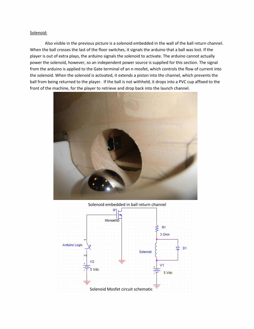
Solenoid:
Also visible in the previous picture is a solenoid embedded in the wall of the ball return channel.
When the ball crosses the last of the floor switches, it signals the arduino that a ball was lost. If the
player is out of extra plays, the arduino signals the solenoid to activate. The arduino cannot actually
power the solenoid, however, so an independent power source is supplied for this section. The signal
from the arduino is applied to the Gate terminal of an n-mosfet, which controls the flow of current into
the solenoid. When the solenoid is activated, it extends a piston into the channel, which prevents the
ball from being returned to the player. If the ball is not withheld, it drops into a PVC cup affixed to the
front of the machine, for the player to retrieve and drop back into the launch channel.
Solenoid embedded in ball return channel
Solenoid Mosfet circuit schematic
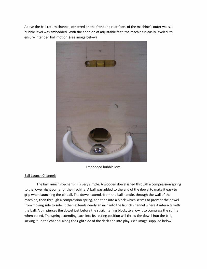
Above the ball return channel, centered on the front and rear faces of the machine’s outer walls, a
bubble level was embedded. With the addition of adjustable feet, the machine is easily leveled, to
ensure intended ball motion. (see image below)
Embedded bubble level
Ball Launch Channel:
The ball launch mechanism is very simple. A wooden dowel is fed through a compression spring
to the lower right corner of the machine. A ball was added to the end of the dowel to make it easy to
grip when launching the pinball. The dowel extends from the ball handle, through the wall of the
machine, then through a compression spring, and then into a block which serves to prevent the dowel
from moving side to side. It then extends nearly an inch into the launch channel where it interacts with
the ball. A pin pierces the dowel just before the straightening block, to allow it to compress the spring
when pulled. The spring extending back into its resting position will throw the dowel into the ball,
kicking it up the channel along the right side of the deck and into play. (see image supplied below)
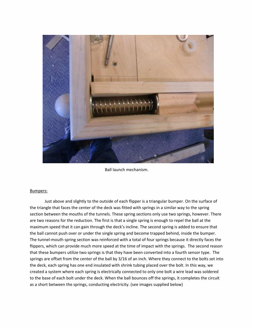
Ball launch mechanism.
Bumpers:
Just above and slightly to the outside of each flipper is a triangular bumper. On the surface of
the triangle that faces the center of the deck was fitted with springs in a similar way to the spring
section between the mouths of the tunnels. These spring sections only use two springs, however. There
are two reasons for the reduction. The first is that a single spring is enough to repel the ball at the
maximum speed that it can gain through the deck’s incline. The second spring is added to ensure that
the ball cannot push over or under the single spring and become trapped behind, inside the bumper.
The tunnel-mouth spring section was reinforced with a total of four springs because it directly faces the
flippers, which can provide much more speed at the time of impact with the springs. The second reason
that these bumpers utilize two springs is that they have been converted into a fourth sensor type. The
springs are offset from the center of the ball by 3/16 of an inch. Where they connect to the bolts set into
the deck, each spring has one end insulated with shrink tubing placed over the bolt. In this way, we
created a system where each spring is electrically connected to only one bolt a wire lead was soldered
to the base of each bolt under the deck. When the ball bounces off the springs, it completes the circuit
as a short between the springs, conducting electricity. (see images supplied below)
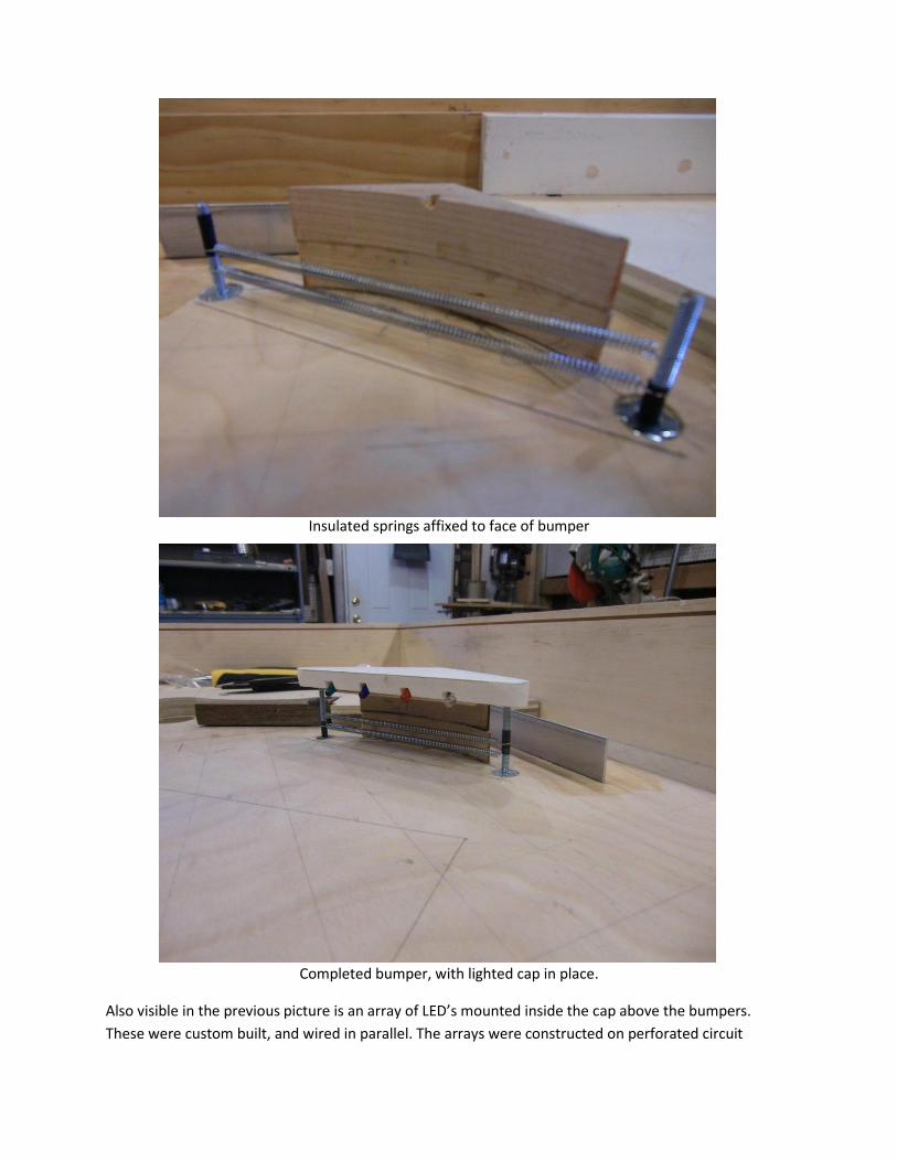
Insulated springs affixed to face of bumper
Completed bumper, with lighted cap in place.
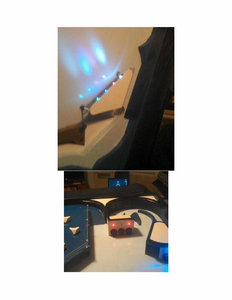
Also visible in the previous picture is an array of LED’s mounted inside the cap above the bumpers.
These were custom built, and wired in parallel. The arrays were constructed on perforated circuit
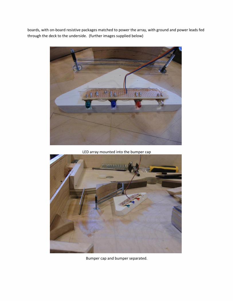
boards, with on-board resistive packages matched to power the array, with ground and power leads fed
through the deck to the underside. (further images supplied below)
LED array mounted into the bumper cap
Bumper cap and bumper separated.
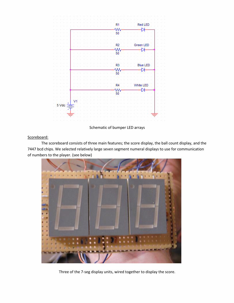
Schematic of bumper LED arrays
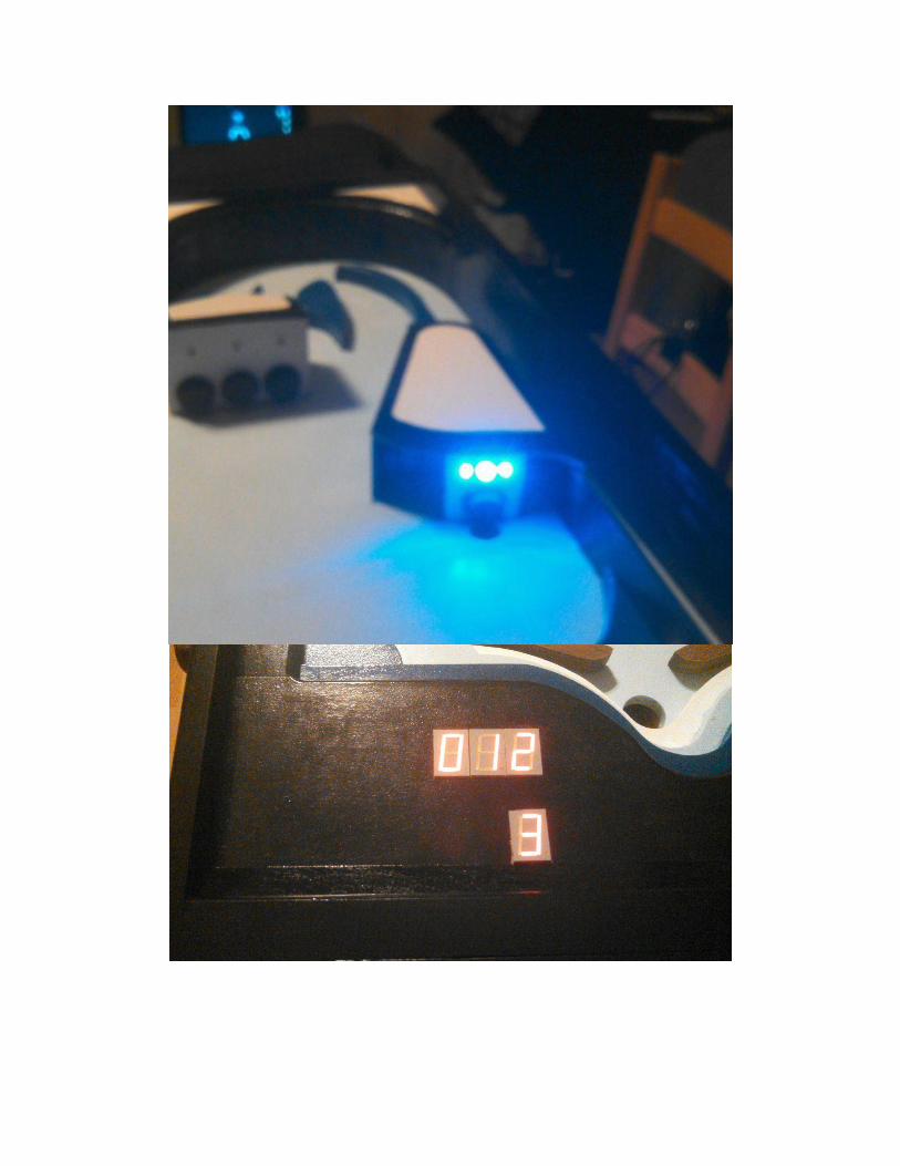
Scoreboard:
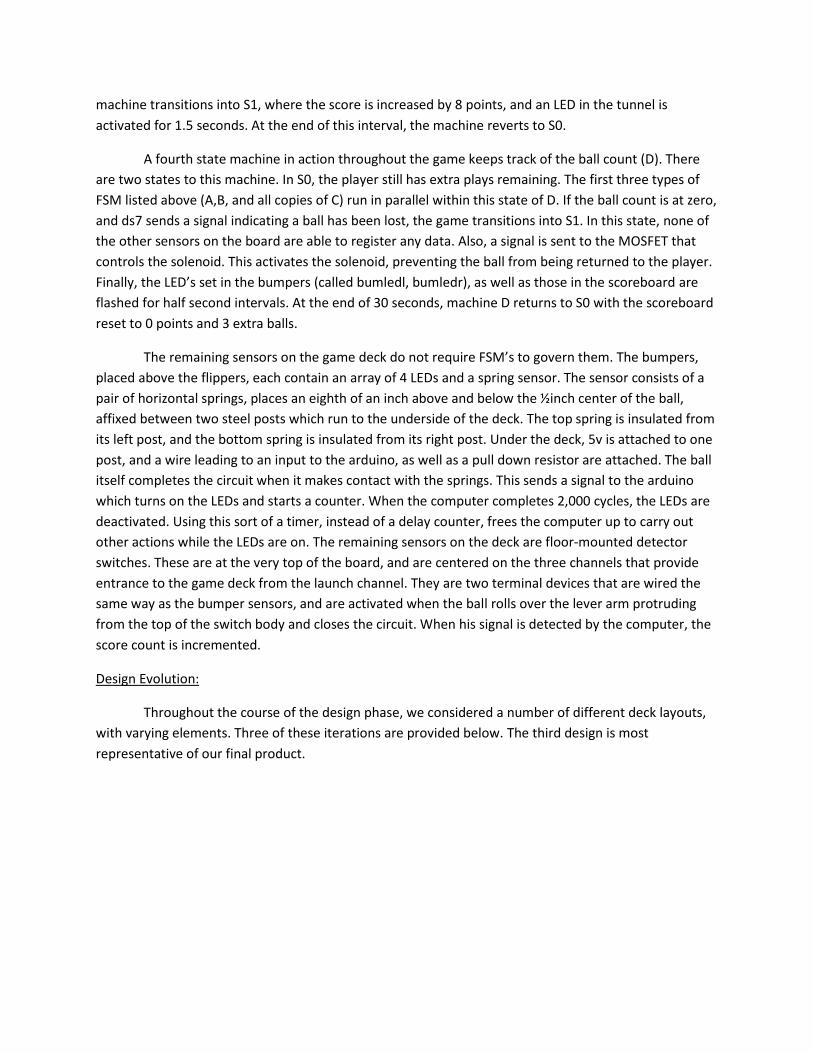
The scoreboard consists of three main features; the score display, the ball count display, and the
7447 bcd chips. We selected relatively large seven segment numeral displays to use for communication
of numbers to the player. (see below)
Three of the 7-seg display units, wired together to display the score.
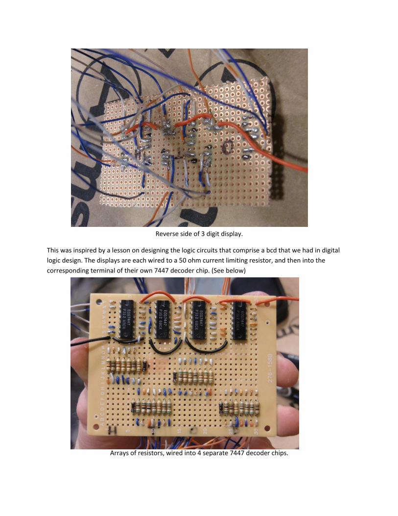
Reverse side of 3 digit display.
This was inspired by a lesson on designing the logic circuits that comprise a bcd that we had in digital
logic design. The displays are each wired to a 50 ohm current limiting resistor, and then into the
corresponding terminal of their own 7447 decoder chip. (See below)
Arrays of resistors, wired into 4 separate 7447 decoder chips.
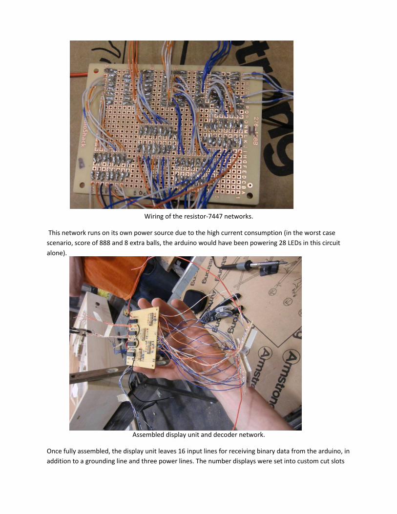
Wiring of the resistor-7447 networks.
This network runs on its own power source due to the high current consumption (in the worst case
scenario, score of 888 and 8 extra balls, the arduino would have been powering 28 LEDs in this circuit
alone).
Assembled display unit and decoder network.
Once fully assembled, the display unit leaves 16 input lines for receiving binary data from the arduino, in
addition to a grounding line and three power lines. The number displays were set into custom cut slots
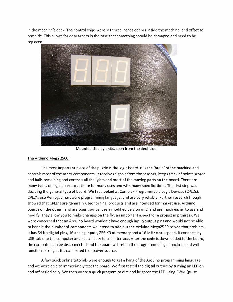
in the machine’s deck. The control chips were set three inches deeper inside the machine, and offset to
one side. This allows for easy access in the case that something should be damaged and need to be
replaced.
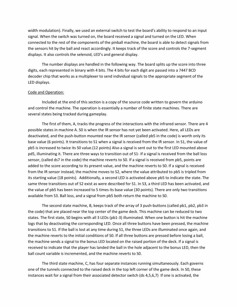
Mounted display units, seen from the deck side.
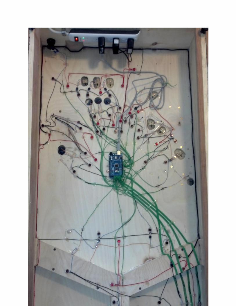
The Arduino Mega 2560:
The most important piece of the puzzle is the logic board. It is the ‘brain’ of the machine and
controls most of the other components. It receives signals from the sensors, keeps track of points scored
and balls remaining and controls all the lights and most of the moving parts on the board. There are
many types of logic boards out there for many uses and with many specifications. The first step was
deciding the general type of board. We first looked at Complex Programmable Logic Devices (CPLDs).
CPLD’s use Verilog, a hardware programming language, and are very reliable. Further research though
showed that CPLD’s are generally used for final products and are intended for market use. Arduino
boards on the other hand are open source, use a modified version of C, and are much easier to use and
modify. They allow you to make changes on the fly, an important aspect for a project in progress. We
were concerned that an Arduino board wouldn’t have enough input/output pins and would not be able
to handle the number of components we intend to add but the Arduino Mega2560 solved that problem.
It has 54 i/o digital pins, 16 analog inputs, 256 KB of memory and a 16 MHz clock speed. It connects by
USB cable to the computer and has an easy to use interface. After the code is downloaded to the board,
the computer can be disconnected and the board will retain the programmed logic function, and will
function as long as it’s connected to a power source.
A few quick online tutorials were enough to get a hang of the Arduino programming language
and we were able to immediately test the board. We first tested the digital output by turning an LED on
and off periodically. We then wrote a quick program to dim and brighten the LED using PWM (pulse
width modulation). Finally, we used an external switch to test the board’s ability to respond to an input
signal. When the switch was turned on, the board received a signal and turned on the LED. When
connected to the rest of the components of the pinball machine, the board is able to detect signals from
the sensors hit by the ball and react accordingly. It keeps track of the score and controls the 7-segment
displays. It also controls the selenoid, LED’s and general display.
The number displays are handled in the following way. The board splits up the score into three
digits, each represented in binary with 4 bits. The 4 bits for each digit are passed into a 7447 BCD
decoder chip that works as a multiplexer to send individual signals to the appropriate segment of the
LED displays.
Code and Operation:
Included at the end of this section is a copy of the source code written to govern the arduino
and control the machine. The operation is essentially a number of finite state machines. There are
several states being tracked during gameplay.
The first of them, A, tracks the progress of the interactions with the infrared sensor. There are 4
possible states in machine A. S0 is when the IR sensor has not yet been activated. Here, all LEDs are
deactivated, and the push-button mounted near the IR sensor (called pb5 in the code) is worth only its
base value (6 points). It transitions to S1 when a signal is received from the IR sensor. In S1, the value of
pb5 is increased to twice its S0 value.(12 points) Also a signal is sent out to the first LED mounted above
pd5, illuminating it. There are three ways to transition out of S1- If a signal is received from the ball loss
sensor, (called ds7 in the code) the machine reverts to S0. If a signal is received from pb5, points are
added to the score according to its present value, and the machine reverts to S0. If a signal is received
from the IR sensor instead, the machine moves to S2, where the value attributed to pb5 is tripled from
its starting value (18 points). Additionally, a second LED is activated above pb5 to indicate the state. The
same three transitions out of S2 exist as were described for S1. In S3, a third LED has been activated, and
the value of pb5 has been increased to 5 times its base value (30 points). There are only two transitions
available from S3. Ball loss, and a signal from pb5 both return the machine to S0.
The second state machine, B, keeps track of the array of 3 push-buttons (called pb1, pb2, pb3 in
the code) that are placed near the top center of the game deck. This machine can be reduced to two
states. The first state, S0 begins with all 3 LEDs (pb1-3) illuminated. When one button is hit the machine
logs that by deactivating the corresponding LED. Once all three buttons have been pressed, the machine
transitions to S1. If the ball is lost at any time during S1, the three LEDs are illuminated once again, and
the machine reverts to the initial conditions of S0. If all three buttons are pressed before losing a ball,
the machine sends a signal to the bonus LED located on the raised portion of the deck. If a signal is
received to indicate that the player has landed the ball in the hole adjacent to the bonus LED, then the
ball count variable is incremented, and the machine reverts to S0.
The third state machine, C, has four separate instances running simultaneously. Each governs
one of the tunnels connected to the raised deck in the top left corner of the game deck. In S0, these
instances wait for a signal from their associated detector switch (ds 4,5,6,7) If one is activated, the
machine transitions into S1, where the score is increased by 8 points, and an LED in the tunnel is
activated for 1.5 seconds. At the end of this interval, the machine reverts to S0.
A fourth state machine in action throughout the game keeps track of the ball count (D). There
are two states to this machine. In S0, the player still has extra plays remaining. The first three types of
FSM listed above (A,B, and all copies of C) run in parallel within this state of D. If the ball count is at zero,
and ds7 sends a signal indicating a ball has been lost, the game transitions into S1. In this state, none of
the other sensors on the board are able to register any data. Also, a signal is sent to the MOSFET that
controls the solenoid. This activates the solenoid, preventing the ball from being returned to the player.
Finally, the LED’s set in the bumpers (called bumledl, bumledr), as well as those in the scoreboard are
flashed for half second intervals. At the end of 30 seconds, machine D returns to S0 with the scoreboard
reset to 0 points and 3 extra balls.
The remaining sensors on the game deck do not require FSM’s to govern them. The bumpers,
placed above the flippers, each contain an array of 4 LEDs and a spring sensor. The sensor consists of a
pair of horizontal springs, places an eighth of an inch above and below the ½inch center of the ball,
affixed between two steel posts which run to the underside of the deck. The top spring is insulated from
its left post, and the bottom spring is insulated from its right post. Under the deck, 5v is attached to one
post, and a wire leading to an input to the arduino, as well as a pull down resistor are attached. The ball
itself completes the circuit when it makes contact with the springs. This sends a signal to the arduino
which turns on the LEDs and starts a counter. When the computer completes 2,000 cycles, the LEDs are
deactivated. Using this sort of a timer, instead of a delay counter, frees the computer up to carry out
other actions while the LEDs are on. The remaining sensors on the deck are floor-mounted detector
switches. These are at the very top of the board, and are centered on the three channels that provide
entrance to the game deck from the launch channel. They are two terminal devices that are wired the
same way as the bumper sensors, and are activated when the ball rolls over the lever arm protruding
from the top of the switch body and closes the circuit. When his signal is detected by the computer, the
score count is incremented.
Design Evolution:
Throughout the course of the design phase, we considered a number of different deck layouts,
with varying elements. Three of these iterations are provided below. The third design is most
representative of our final product.
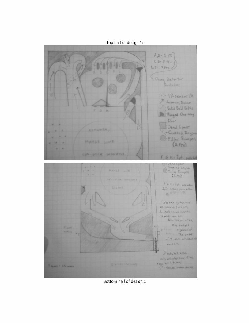
Top half of design 1:
Bottom half of design 1
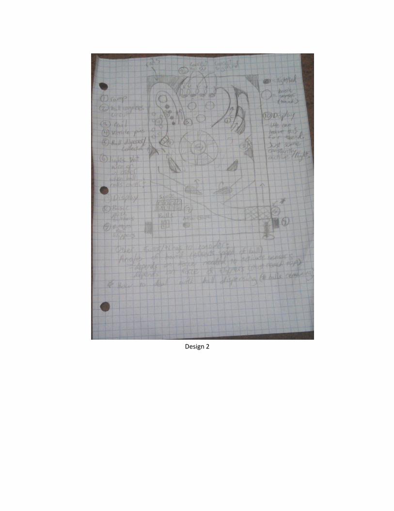
Design 2
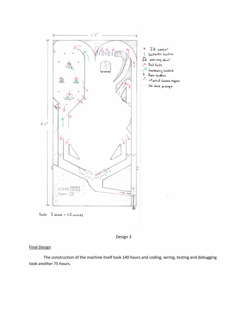
Design 3
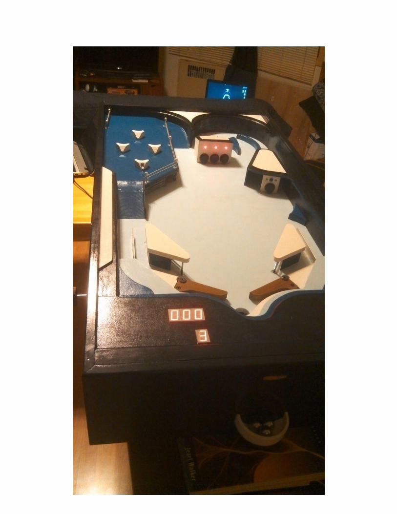
Final Design
The construction of the machine itself took 140 hours and coding, wiring, testing and debugging
took another 75 hours.
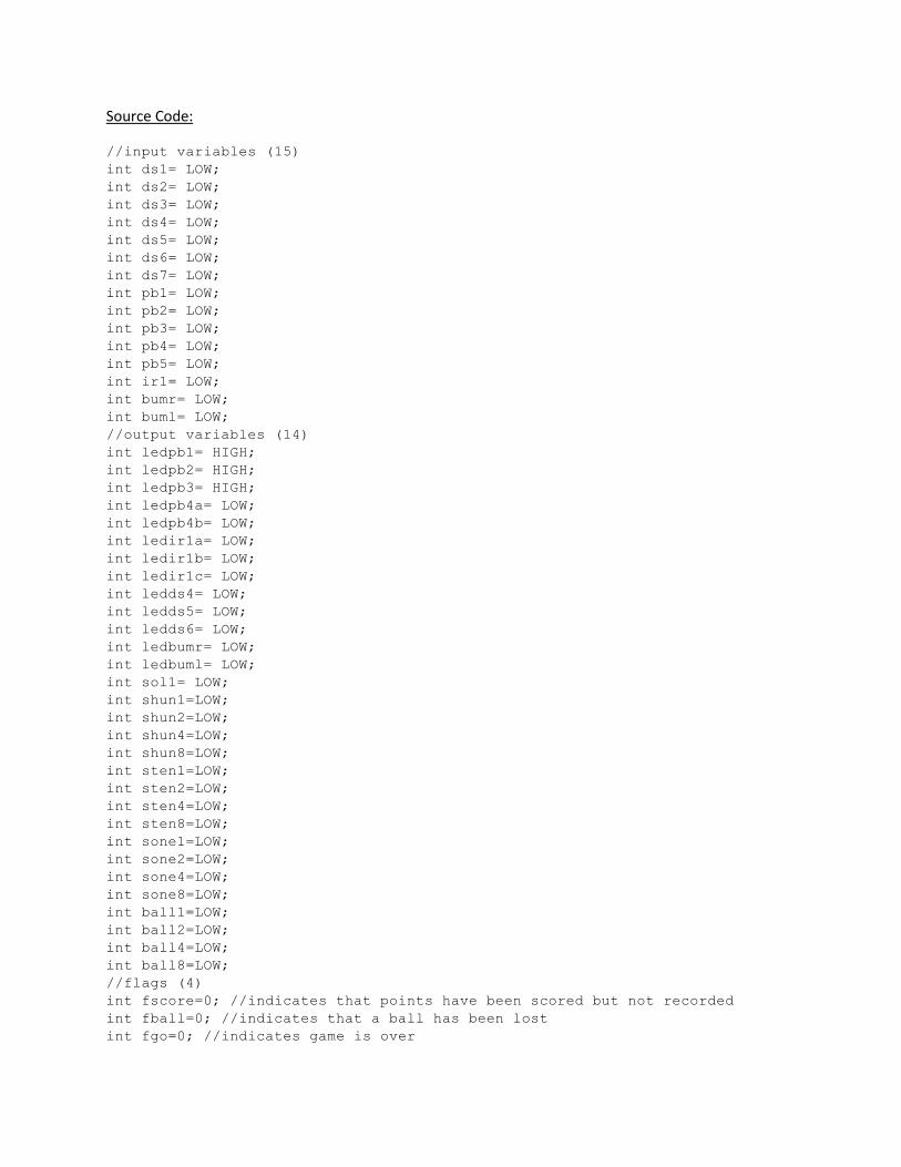
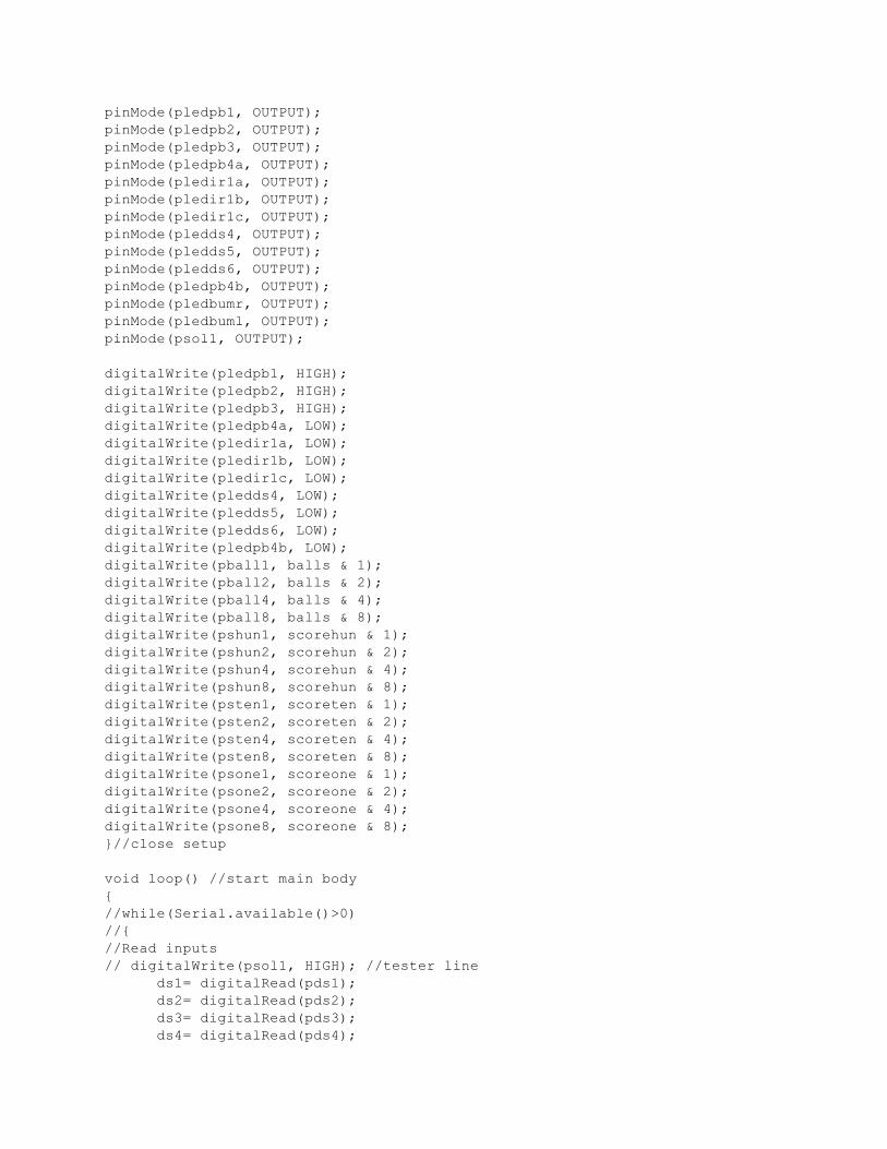
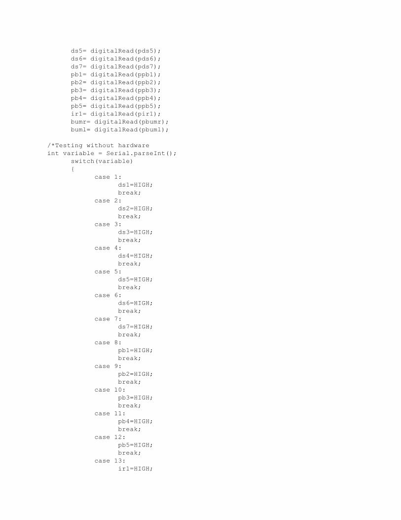
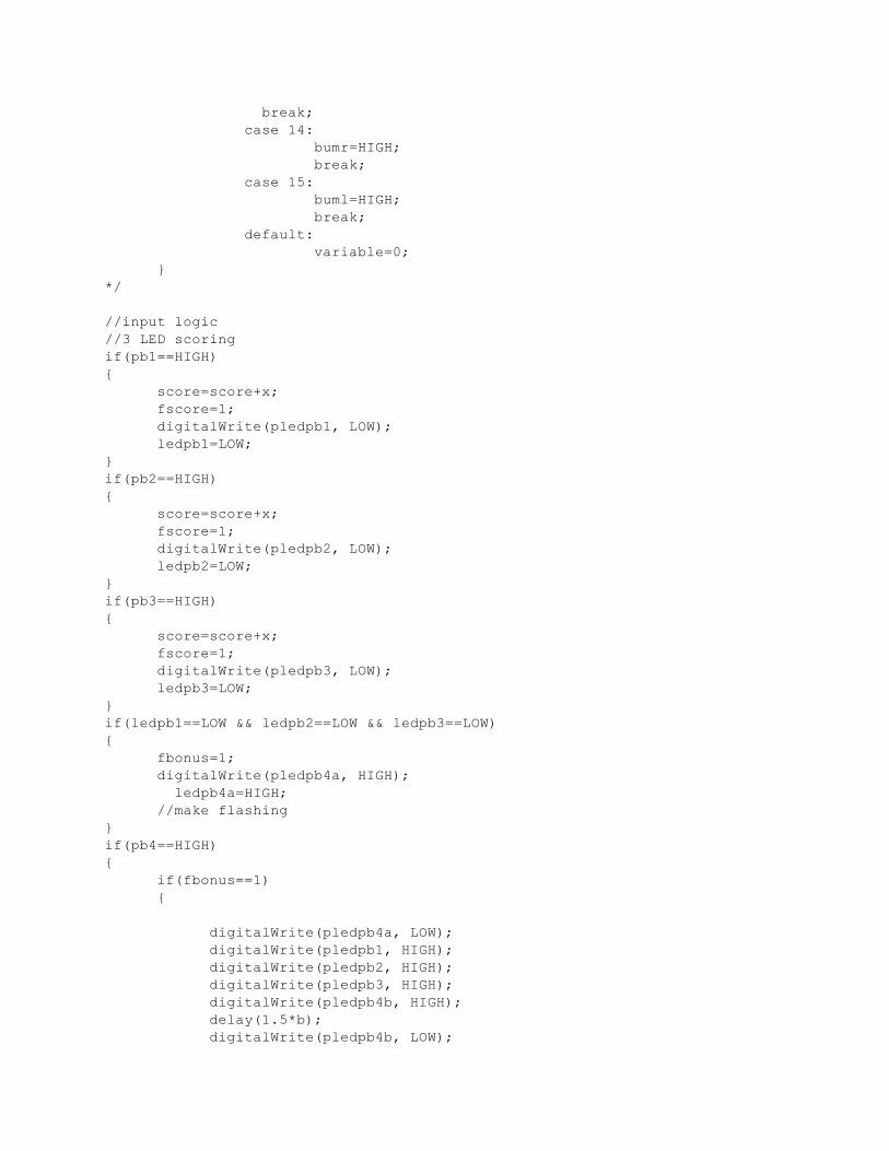
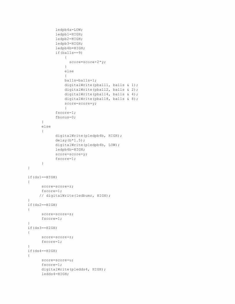
Source Code:
//input variables (15)
int ds1= LOW;
int ds2= LOW;
int ds3= LOW;
int ds4= LOW;
int ds5= LOW;
int ds6= LOW;
int ds7= LOW;
int pb1= LOW;
int pb2= LOW;
int pb3= LOW;
int pb4= LOW;
int pb5= LOW;
int ir1= LOW;
int bumr= LOW;
int buml= LOW;
//output variables (14)
int ledpb1= HIGH;
int ledpb2= HIGH;
int ledpb3= HIGH;
int ledpb4a= LOW;
int ledpb4b= LOW;
int ledir1a= LOW;
int ledir1b= LOW;
int ledir1c= LOW;
int ledds4= LOW;
int ledds5= LOW;
int ledds6= LOW;
int ledbumr= LOW;
int ledbuml= LOW;
int sol1= LOW;
int shun1=LOW;
int shun2=LOW;
int shun4=LOW;
int shun8=LOW;
int sten1=LOW;
int sten2=LOW;
int sten4=LOW;
int sten8=LOW;
int sone1=LOW;
int sone2=LOW;
int sone4=LOW;
int sone8=LOW;
int ball1=LOW;
int ball2=LOW;
int ball4=LOW;
int ball8=LOW;
//flags (4)
int fscore=0; //indicates that points have been scored but not recorded
int fball=0; //indicates that a ball has been lost
int fgo=0; //indicates game is over
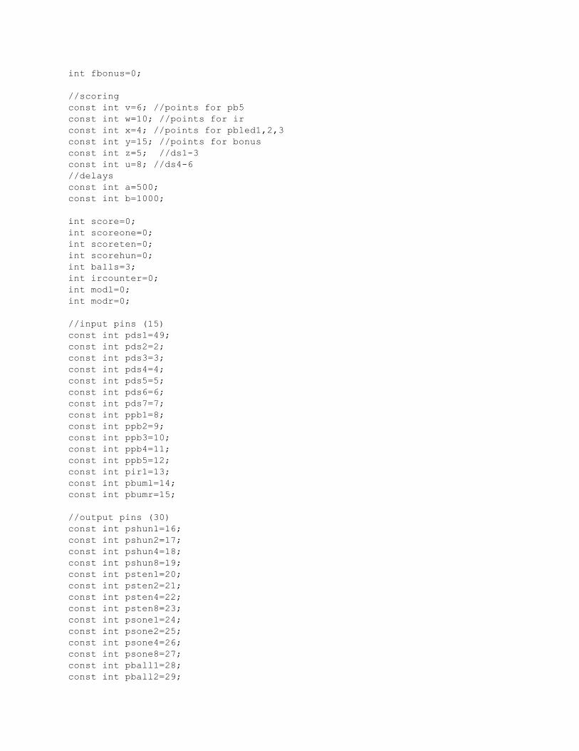
int fbonus=0;
//scoring
const int v=6; //points for pb5
const int w=10; //points for ir
const int x=4; //points for pbled1,2,3
const int y=15; //points for bonus
const int z=5; //ds1-3
const int u=8; //ds4-6
//delays
const int a=500;
const int b=1000;
int score=0;
int scoreone=0;
int scoreten=0;
int scorehun=0;
int balls=3;
int ircounter=0;
int modl=0;
int modr=0;
//input pins (15)
const int pds1=49;
const int pds2=2;
const int pds3=3;
const int pds4=4;
const int pds5=5;
const int pds6=6;
const int pds7=7;
const int ppb1=8;
const int ppb2=9;
const int ppb3=10;
const int ppb4=11;
const int ppb5=12;
const int pir1=13;
const int pbuml=14;
const int pbumr=15;
//output pins (30)
const int pshun1=16;
const int pshun2=17;
const int pshun4=18;
const int pshun8=19;
const int psten1=20;
const int psten2=21;
const int psten4=22;
const int psten8=23;
const int psone1=24;
const int psone2=25;
const int psone4=26;
const int psone8=27;
const int pball1=28;
const int pball2=29;
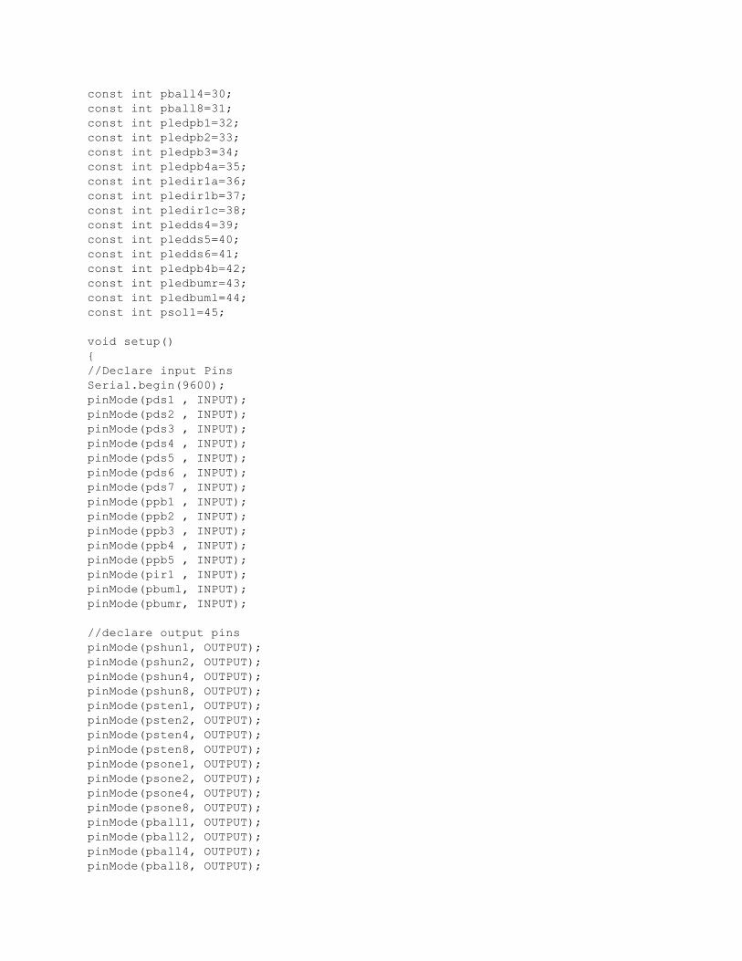
const int pball4=30;
const int pball8=31;
const int pledpb1=32;
const int pledpb2=33;
const int pledpb3=34;
const int pledpb4a=35;
const int pledir1a=36;
const int pledir1b=37;
const int pledir1c=38;
const int pledds4=39;
const int pledds5=40;
const int pledds6=41;
const int pledpb4b=42;
const int pledbumr=43;
const int pledbuml=44;
const int psol1=45;
void setup()
{
//Declare input Pins
Serial.begin(9600);
pinMode(pds1 , INPUT);
pinMode(pds2 , INPUT);
pinMode(pds3 , INPUT);
pinMode(pds4 , INPUT);
pinMode(pds5 , INPUT);
pinMode(pds6 , INPUT);
pinMode(pds7 , INPUT);
pinMode(ppb1 , INPUT);
pinMode(ppb2 , INPUT);
pinMode(ppb3 , INPUT);
pinMode(ppb4 , INPUT);
pinMode(ppb5 , INPUT);
pinMode(pir1 , INPUT);
pinMode(pbuml, INPUT);
pinMode(pbumr, INPUT);
//declare output pins
pinMode(pshun1, OUTPUT);
pinMode(pshun2, OUTPUT);
pinMode(pshun4, OUTPUT);
pinMode(pshun8, OUTPUT);
pinMode(psten1, OUTPUT);
pinMode(psten2, OUTPUT);
pinMode(psten4, OUTPUT);
pinMode(psten8, OUTPUT);
pinMode(psone1, OUTPUT);
pinMode(psone2, OUTPUT);
pinMode(psone4, OUTPUT);
pinMode(psone8, OUTPUT);
pinMode(pball1, OUTPUT);
pinMode(pball2, OUTPUT);
pinMode(pball4, OUTPUT);
pinMode(pball8, OUTPUT);
pinMode(pledpb1, OUTPUT);
pinMode(pledpb2, OUTPUT);
pinMode(pledpb3, OUTPUT);
pinMode(pledpb4a, OUTPUT);
pinMode(pledir1a, OUTPUT);
pinMode(pledir1b, OUTPUT);
pinMode(pledir1c, OUTPUT);
pinMode(pledds4, OUTPUT);
pinMode(pledds5, OUTPUT);
pinMode(pledds6, OUTPUT);
pinMode(pledpb4b, OUTPUT);
pinMode(pledbumr, OUTPUT);
pinMode(pledbuml, OUTPUT);
pinMode(psol1, OUTPUT);
digitalWrite(pledpb1, HIGH);
digitalWrite(pledpb2, HIGH);
digitalWrite(pledpb3, HIGH);
digitalWrite(pledpb4a, LOW);
digitalWrite(pledir1a, LOW);
digitalWrite(pledir1b, LOW);
digitalWrite(pledir1c, LOW);
digitalWrite(pledds4, LOW);
digitalWrite(pledds5, LOW);
digitalWrite(pledds6, LOW);
digitalWrite(pledpb4b, LOW);
digitalWrite(pball1, balls & 1);
digitalWrite(pball2, balls & 2);
digitalWrite(pball4, balls & 4);
digitalWrite(pball8, balls & 8);
digitalWrite(pshun1, scorehun & 1);
digitalWrite(pshun2, scorehun & 2);
digitalWrite(pshun4, scorehun & 4);
digitalWrite(pshun8, scorehun & 8);
digitalWrite(psten1, scoreten & 1);
digitalWrite(psten2, scoreten & 2);
digitalWrite(psten4, scoreten & 4);
digitalWrite(psten8, scoreten & 8);
digitalWrite(psone1, scoreone & 1);
digitalWrite(psone2, scoreone & 2);
digitalWrite(psone4, scoreone & 4);
digitalWrite(psone8, scoreone & 8);
}//close setup
void loop() //start main body
{
//while(Serial.available()>0)
//{
//Read inputs
// digitalWrite(psol1, HIGH); //tester line
ds1= digitalRead(pds1);
ds2= digitalRead(pds2);
ds3= digitalRead(pds3);
ds4= digitalRead(pds4);
ds5= digitalRead(pds5);
ds6= digitalRead(pds6);
ds7= digitalRead(pds7);
pb1= digitalRead(ppb1);
pb2= digitalRead(ppb2);
pb3= digitalRead(ppb3);
pb4= digitalRead(ppb4);
pb5= digitalRead(ppb5);
ir1= digitalRead(pir1);
bumr= digitalRead(pbumr);
buml= digitalRead(pbuml);
/*Testing without hardware
int variable = Serial.parseInt();
switch(variable)
{
case 1:
ds1=HIGH;
break;
case 2:
ds2=HIGH;
break;
case 3:
ds3=HIGH;
break;
case 4:
ds4=HIGH;
break;
case 5:
ds5=HIGH;
break;
case 6:
ds6=HIGH;
break;
case 7:
ds7=HIGH;
break;
case 8:
pb1=HIGH;
break;
case 9:
pb2=HIGH;
break;
case 10:
pb3=HIGH;
break;
case 11:
pb4=HIGH;
break;
case 12:
pb5=HIGH;
break;
case 13:
ir1=HIGH;
break;
case 14:
bumr=HIGH;
break;
case 15:
buml=HIGH;
break;
default:
variable=0;
}
*/
//input logic
//3 LED scoring
if(pb1==HIGH)
{
score=score+x;
fscore=1;
digitalWrite(pledpb1, LOW);
ledpb1=LOW;
}
if(pb2==HIGH)
{
score=score+x;
fscore=1;
digitalWrite(pledpb2, LOW);
ledpb2=LOW;
}
if(pb3==HIGH)
{
score=score+x;
fscore=1;
digitalWrite(pledpb3, LOW);
ledpb3=LOW;
}
if(ledpb1==LOW && ledpb2==LOW && ledpb3==LOW)
{
fbonus=1;
digitalWrite(pledpb4a, HIGH);
ledpb4a=HIGH;
//make flashing
}
if(pb4==HIGH)
{
if(fbonus==1)
{
digitalWrite(pledpb4a, LOW);
digitalWrite(pledpb1, HIGH);
digitalWrite(pledpb2, HIGH);
digitalWrite(pledpb3, HIGH);
digitalWrite(pledpb4b, HIGH);
delay(1.5*b);
digitalWrite(pledpb4b, LOW);
ledpb4a=LOW;
ledpb1=HIGH;
ledpb2=HIGH;
ledpb3=HIGH;
ledpb4b=HIGH;
if(balls==9)
{
score=score+2*y;
}
else
{
balls=balls+1;
digitalWrite(pball1, balls & 1);
digitalWrite(pball2, balls & 2);
digitalWrite(pball4, balls & 4);
digitalWrite(pball8, balls & 8);
score=score+y;
}
fscore=1;
fbonus=0;
}
else
{
digitalWrite(pledpb4b, HIGH);
delay(b*1.5);
digitalWrite(pledpb4b, LOW);
ledpb4b=HIGH;
score=score+y;
fscore=1;
}
}
if(ds1==HIGH)
{
score=score+z;
fscore=1;
// digitalWrite(ledbumr, HIGH);
}
if(ds2==HIGH)
{
score=score+z;
fscore=1;
}
if(ds3==HIGH)
{
score=score+z;
fscore=1;
}
if(ds4==HIGH)
{
score=score+u;
fscore=1;
digitalWrite(pledds4, HIGH);
ledds4=HIGH;
delay(b);
digitalWrite(pledds4, LOW);
}
if(ds5==HIGH)
{
score=score+u;
fscore=1;
digitalWrite(pledds5, HIGH);
ledds5=HIGH;
delay(b);
digitalWrite(pledds5, LOW);
}
if(ds6==HIGH)
{
score=score+u;
fscore=1;
digitalWrite(pledds6, HIGH);
ledds6=HIGH;
delay(b);
digitalWrite(pledds6, LOW);
}
if(ir1==HIGH)
{
score=score+w;
fscore=1;
ircounter=ircounter+1;
switch(ircounter)
{
case 1:
digitalWrite(pledir1a, HIGH);
ledir1a=HIGH;
break;
case 2:
digitalWrite(pledir1b, HIGH);
ledir1b=HIGH;
break;
default:
digitalWrite(pledir1c, HIGH);
ledir1c=HIGH;
break;
}
}
if(pb5==HIGH)
{
switch(ircounter)
{
case 0:
score=score+v;
fscore=1;
break;
case 1:
score=score+2*v;
fscore=1;
break;
case 2:
score=score+3*v;
fscore=1;
break;
default:
score=score+5*v;
fscore=1;
break;
}
digitalWrite(pledir1a, LOW);
digitalWrite(pledir1b, LOW);
digitalWrite(pledir1c, LOW);
ledir1a=LOW;
ledir1b=LOW;
ledir1c=LOW;
ircounter=0;
}
if(bumr==HIGH )
{
digitalWrite(pledbumr, HIGH);
modr=0;
// delay(b);
// digitalWrite(pledbumr, LOW);
// score=score+x;
// score=1;
}
if((modr%2500)==2499)
{
digitalWrite(pledbumr, LOW);
}
else
{
modr=modr+1;
}
if(buml==HIGH)
{
digitalWrite(pledbuml, HIGH);
modl=0;
// delay(b);
// digitalWrite(pledbuml, LOW);
// ledbuml=HIGH;
// score=score+x;
// fscore=1;
}
if((modl%2500)==2499)
{
digitalWrite(pledbuml, LOW);
}
else
{
modl=modl+1;
}
if(ds7==HIGH)
{
fball=1;
}
//balls
if(fball==1)
{
if(balls==0)
{
fgo=1;
}
else
{
balls=balls-1;
digitalWrite(pball1, balls & 1);
digitalWrite(pball2, balls & 2);
digitalWrite(pball4, balls & 4);
digitalWrite(pball8, balls & 8);
delay(b);
}
digitalWrite(pledpb1, HIGH);
digitalWrite(pledpb2, HIGH);
digitalWrite(pledpb3, HIGH);
digitalWrite(pledpb4a, LOW);
digitalWrite(pledir1a, LOW);
digitalWrite(pledir1b, LOW);
digitalWrite(pledir1c, LOW);
digitalWrite(pledds4, LOW);
digitalWrite(pledds5, LOW);
digitalWrite(pledds6, LOW);
digitalWrite(pledpb4b, LOW);
ledpb1=HIGH;
ledpb2= HIGH;
ledpb3= HIGH;
ledpb4a= LOW;
ledir1a= LOW;
ledir1b= LOW;
ledir1c= LOW;
ledds4= LOW;
ledds5= LOW;
ledds6= LOW;
ledpb4b= LOW;
fball=0;
ircounter=0;
}
//if gameover or initial loop, reset/set variables
if(fgo==1)
{
//basic variables
digitalWrite(psol1, HIGH);
sol1=HIGH;
for(int g=0; g<60; g=g+1)
{
digitalWrite(pledbuml, HIGH);
digitalWrite(pledbumr, HIGH);
digitalWrite(pball1, balls & 1);
digitalWrite(pball2, balls & 2);
digitalWrite(pball4, balls & 4);
digitalWrite(pball8, balls & 8);
digitalWrite(pshun1, scorehun & 1);
digitalWrite(pshun2, scorehun & 2);
digitalWrite(pshun4, scorehun & 4);
digitalWrite(pshun8, scorehun & 8);
digitalWrite(psten1, scoreten & 1);
digitalWrite(psten2, scoreten & 2);
digitalWrite(psten4, scoreten & 4);
digitalWrite(psten8, scoreten & 8);
digitalWrite(psone1, scoreone & 1);
digitalWrite(psone2, scoreone & 2);
digitalWrite(psone4, scoreone & 4);
digitalWrite(psone8, scoreone & 8);
delay(a/2);
digitalWrite(pledbuml, LOW);
digitalWrite(pledbumr, LOW);
digitalWrite(pball1, HIGH);
digitalWrite(pball2, HIGH);
digitalWrite(pball4, HIGH);
digitalWrite(pball8, HIGH);
digitalWrite(pshun1, HIGH);
digitalWrite(pshun2, HIGH);
digitalWrite(pshun4, HIGH);
digitalWrite(pshun8, HIGH);
digitalWrite(psten1, HIGH);
digitalWrite(psten2, HIGH);
digitalWrite(psten4, HIGH);
digitalWrite(psten8, HIGH);
digitalWrite(psone1, HIGH);
digitalWrite(psone2, HIGH);
digitalWrite(psone4, HIGH);
digitalWrite(psone8, HIGH);
delay(a/2);
}
digitalWrite(psol1, LOW);
sol1= LOW;
score=0;
scoreone=0;
scoreten=0;
scorehun=0;
balls=3;
digitalWrite(pball1, balls & 1);
digitalWrite(pball2, balls & 2);
digitalWrite(pball4, balls & 4);
digitalWrite(pball8, balls & 8);
ledpb1=HIGH;
ledpb2=HIGH;
ledpb3=HIGH;
ircounter=0;
fscore=1;
fgo=0;
}
//scoring
if(fscore==1)
{
if(score>999)
{
score=999;
}
else
{
scorehun=score/100;
scoreten=((score-(scorehun*100))/10);
scoreone=score-(scorehun*100)-(scoreten*10);
digitalWrite(pshun1, scorehun & 1);
digitalWrite(pshun2, scorehun & 2);
digitalWrite(pshun4, scorehun & 4);
digitalWrite(pshun8, scorehun & 8);
digitalWrite(psten1, scoreten & 1);
digitalWrite(psten2, scoreten & 2);
digitalWrite(psten4, scoreten & 4);
digitalWrite(psten8, scoreten & 8);
digitalWrite(psone1, scoreone & 1);
digitalWrite(psone2, scoreone & 2);
digitalWrite(psone4, scoreone & 4);
digitalWrite(psone8, scoreone & 8);
fscore=0;
sten1= scoreten & 1;
sten2= scoreten & 2;
sten4= scoreten & 4;
sten8= scoreten & 8;
}
delay(b/2);
}
/*
Serial.print("\n \nScore: ");
Serial.println(score, DEC);
Serial.print("\n LEDIRCA ");
Serial.println(ledir1a, DEC);
Serial.print("\n LEDIRB: ");
Serial.println(ledir1b, DEC);
Serial.print("\n LEDIRC: ");
Serial.println(ledir1c, DEC);
Serial.print("\n LEDDS4: ");
Serial.println(ledds4, DEC);
Serial.print("\n LEDDS5: ");
Serial.println(ledds5, DEC);
Serial.print("\n LEDDS6: ");
Serial.println(ledds6, DEC);
Serial.print("\n LEDPB1: ");
Serial.println(ledpb1, DEC);
Serial.print("\n LEDPB2: ");
Serial.println(ledpb2, DEC);
Serial.print("\n LEDBP3: ");
Serial.println(ledpb3, DEC);
Serial.print("\n LEDBP4b: ");
Serial.println(ledpb4b, DEC);
Serial.print("\n Bonus: ");
Serial.println(ledpb4a, DEC);
Serial.print("\n ircounter: ");
Serial.println(ircounter, DEC);
Serial.print("\n bumpr: ");
Serial.println(ledbumr, DEC);
Serial.print("\n bumpl: ");
Serial.println(ledbuml, DEC);
Serial.print("\n Scoreone: ");
Serial.println(scoreone, DEC);
Serial.print("\n Scoreten: ");
Serial.println(scoreten, DEC);
Serial.print("\n Scorehun: ");
Serial.println(scorehun, DEC);
Serial.print("\n Balls: ");
Serial.println(balls, DEC);
Serial.print("\n sellenoid: ");
Serial.println(sol1, DEC);
Serial.print("\n sten1: ");
Serial.println(sten1, DEC);
Serial.print("\n Sten2: ");
Serial.println(sten2, DEC);
Serial.print("\n Sten4: ");
Serial.println(sten4, DEC);
Serial.print("\n Sten8: ");
Serial.println(sten8, DEC);
*/
//reset input variables
ds1= LOW;
ds2= LOW;
ds3= LOW;
ds4= LOW;
ds5= LOW;
ds6= LOW;
ds7= LOW;
pb1= LOW;
pb2= LOW;
pb3= LOW;
pb4= LOW;
pb5= LOW;
ir1= LOW;
bumr=LOW;
buml=LOW;
ledpb4b=LOW;
ledds4=LOW;
ledds5=LOW;
ledds6=LOW;

sol1=LOW;
ledbumr=LOW;
ledbuml=LOW;
//} //close test
}//close loop