Pilot`s Manual - lxnavigation.com · LX1600 V2.10 Dec. 2008 Page 2 1 Overview The LX 1600 has been...
21
LX 1600 V2.10 Variometer / speedcommand system controlled by PDA, with Flarm interface Pilot`s Manual LX navigation d.o.o. Tkalska 10 SLO 3000 Celje + 386 3 490 46 70 + 386 3 490 46 71 support@lxnavigation.si http://www.lxnavigation.si
-
Upload
truongkhanh -
Category
Documents
-
view
212 -
download
0
Transcript of Pilot`s Manual - lxnavigation.com · LX1600 V2.10 Dec. 2008 Page 2 1 Overview The LX 1600 has been...

LX 1600 V2.10
Variometer / speedcommand system controlled by PDA, with Flarm interface
Pilot`s Manual
LX navigation d.o.o. Tkalska 10 SLO 3000 Celje + 386 3 490 46 70 + 386 3 490 46 71 [email protected] http://www.lxnavigation.si

LX1600 V2.10 Dec. 2008
Page 2
1 Overview
The LX 1600 has been designed from the outset as a variometer/ speedcommand system designed to operate with and be controlled by a PDA (iPAQ, for example). When connected to such equipment and when loaded with compatible operating program, and connected to a suitable GPS source, the pilot has at his command a full competition-capable flight management system that needs only one standard 57mm hole in the instrument panel! Version 2.10 makes possible to transfer Flarm data from Flarm unit via LX 1600 toward PDA. In addition to its operation by a PDA, the LX 1600 also has four push buttons fitted coincident with the 4 mounting screws that allow the pilot to operate the vario independently of the iPAQ. These controls comprise: • Audio Volume adjustment • Ballast input • MacCready input • Altitude • Vario Response input The unit is available without PDA software or can be ordered as a package including software (SW).
Note!
SW packages currently available: SeeYou Mobile, FlyWithCE Navigator, Winpilot
The LX 1600 cannot operate a second cockpit repeater. If you need this we recommend either the LX 160S or the LX 7000/7007 series.
Note! Obligatory study PDA program manual, if the unit will work in conjunction with PDA.
2 Functions Because the LX 1600 is principally designed for operation with a PDA the really important Pilots` Manual is that provided by the designer of the operating software. This manual for just the LX 1600 will help you to operate the unit as a stand alone unit, or to install the unit and connect it to a PDA. However, it will be helpful to note the controls that are provided on the LX 1600 permit its operation without PDA. These controls are mounted concentric with the mounting screws and enable to following functions to be controlled:

LX1600 V2.10 Dec. 2008
Page 3
2.1 Controls
The function of the four push buttons is as follows: • Speaker knob up to increase audio volume • Speaker knob down to reduce audio volume • Menu buttons (doesn’t matter which is activated) will allow Mc Cready (MC), Ballast,
vario filter (response), altitude and actual baudrate theat is detected from GPS source. Press Menu button as required to find appropriate function and change the value using volume up or down. nc MC setting after using of vol knob ALt altitude adjustment * FiL vario filter adjustment ** bAL input of ballast factor*** bAud information about detected baudrate from GPS * Altimeter adjustment is necessary due to daily pressure changes. This value is sent to PDA, if connected. Recommended setting is field elevation. Altitude adjustment is also possible from PDA. See capture 7. ** To adapt vario needle dynamic, use filter in steps from 0.5 up to 5.0. The most effective filter is 5.0. Recommended value is 3.0. *** Ballast input can be done exclusively after input of so called overload factor. This factor is calculated as follows:
Overload = pilot+glider+ballast / pilot+glider
Overload value is 1.0, if the flight will be performed without ballast. After using of PDA any other units are possible.
Vario/SC mode ind.
Altitude
Averager
Vario/SC needle
SC indicator
Menu button
Volume up ����
Volume down ����

LX1600 V2.10 Dec. 2008
Page 4
All four mentioned parameters can be adjusted via PDA as well, see subsequent chapters for details. There is no confirmation procedure after input, if no change on up/down buttons is detected the unit will change over into main mode automatically. The diagram below shows in detail the function capability of the LX 1600 display. Many of these can be re-programmed by the user through the PDA and can be personalised. Use PDA program manual (SeeYou Mobile and Navigator) for details.
Note! The unit wiring has a special cable with open ends (marked as SC). This can be used as an external SC/Vario command. This function is normally realized after using of a
toggle switch. SC external switch has an absolute priority, if activated the unit will change over to SC without respect on settings defined in PDA. By external switch not active, PDA is able to send change over commands. Active status of the switch can be defined using
of PDA settings. The display functions hardly depend on PDA settings. Default settings without PDA connected are described below.
LOW BATTERY
INDICATOR
GPS STATUS INDICATOR
LOWER NUMBER DISPLAY
NEEDLE SHOWS RELATIVE
NEEDLE SHOWS VARIO
NEEDLE SHOWS NETTO
NEEDLE SHOS INDICATED AIR SPEED (NOT USED)
NEEDLE SHOWS SPEED
COMMAND
NEEDLE
SPEED COMMAND
BAR
SPEED COMMAND MODE INDICATOR
VARIO MODE INDICATOR
LOWER NUMBER SHOWS
TASK / LEG SPEED
UPPER NUMBER DISPLAY
UPPER NUMBER SHOWS FLIGHT / LEG TIME
UPPER NUMBER SHOWS INTEGRATOR
LOWER NUMBER SHOWS
ALTITUDE / DISTANCE /
FINAL GLIDE

LX1600 V2.10 Dec. 2008
Page 5
Note! The GPS status indicator has the following meanings:
GPS symbol not present = no GPS data received GPS symbol blinking = GPS Bad GPS symbol present all the time = GPS OK
Altitude
Vario/SC status
Averager

LX1600 V2.10 Dec. 2008
Page 6
2.2 Stand alone operation The unit can be used as a stand alone electronic variometer and speed command instrument at any time. In this case only limited functions will be available and no system setting changes possible. All adjustments have to be made using the push buttons on the unit.
3 Installation
Installation is straightforward and well within the capability of most glider pilots. The following advice may, however, be helpful.
3.1 Mechanical Installation One 57 mm diameter circular cut out is required but you need to allow for the overall dimensions of the unit which are as follows:
60mm width 60mm height 140 mm length with connectors
The unit is attached by 4 hollow bolts at its 4 corners and the positioning of these holes is the same as any other instrument of this size. The control knobs are mounted concentrically around the hollow bolts and are fixed using the internal screw.
Installation procedure
• Extend instrument fixing holes to 6.5 mm • Remove four buttons from axis, use special tool delivered with the unit • Remove four bolts, use 8mm tool • Insert LX 1600 into the cut out and fix it using four bolts provided • Check functioning of push buttons, if they are blocked or your instrument panel is too
thin, place a ring (included) between the instrument and the panel to achieve the correct functioning.
• Fix all four push buttons
Note! If some push button will block after the bolt has been turned down, it is necessary to insert
additionally spring which is also delivery included.

LX1600 V2.10 Dec. 2008
Page 7
3.2 Pneumatic Connection There are three (3) pressure inlets on the rear of the instrument and all are clearly labelled. It is fundamental that these connections are made correctly. They are labelled as follows:
� TE (Pst) � PSt � Ptot The Pst and Ptot are used by the instrument for airspeed measurement whereas TE(Pst) provides the input for the variometer. There are 2 ways of connecting the instrument depending upon the type of installation required. One provides TE probe compensation and the other gives electronic TE compensation. The latter can only be achieved by the use of a PDA and SW. The factory setting is TE probe. TE Probe Compensation
� TE(Pst) connect to the glider TE probe � Pst connect to the glider static � Ptot connect to the glider pitot (total pressure) Example: TE probe connection

LX1600 V2.10 Dec. 2008
Page 8
Electronic TE Compensation � TE(Pst) connect to the glider static � Pst connect to the glider static � Ptot connect to the glider pitot (total pressure) Example: electronic TE compensation If you select the electronic TE compensation system then you must carry out a test flight in smooth air to set it up properly. There are 2 parameters that will need to be checked and adjusted; the TE percentage setting and the vario damping (vario filter). The suggested procedure is as follows:
� Take a tow high enough to find smooth air and release � Then accelerate up to about 100 knots and stabilise the airspeed � Pull up at about 1.5g (no more) and observe the vario indication If the vario indicates up during the ascent after the pull up then the compensation is insufficient. If it indicates sink then the compensation is too high. You adjust as follows: � Increase compensation by increasing the percentage compensation (the norm is 100% but
you can go above or below this) � Decrease the percentage if the compensation needs reducing
The adjustment is carried out by using the PDA and you will need to cross refer to the PDA Manual to see how this should be done. The vario damping (vario filter) is set to ensure that the needle response is suitable for your requirements; you may need to adjust this from time to time if you fly in different conditions where turbulence may be a factor. The damping can be adjusted by the knob on the dial of the vario or by using the PDA in which case you will need to refer to the PDA Manual to find out how this can be done.
LX1600 V2.10 Dec. 2008
Page 9
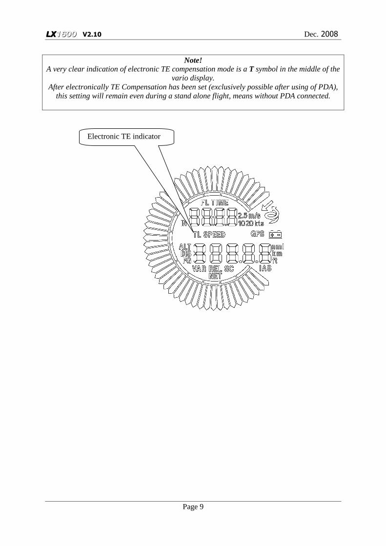
Note!
A very clear indication of electronic TE compensation mode is a T symbol in the middle of the vario display.
After electronically TE Compensation has been set (exclusively possible after using of PDA), this setting will remain even during a stand alone flight, means without PDA connected.
Electronic TE indicator

LX1600 V2.10 Dec. 2008
Page 10
3.3 Electrical connections The electrical connections are clearly marked and the pre-assembled cables make it very easy to connect all the components. The unit has no ON/OFF switch, use avionic master switch or install a separate switch.
Note! There is no internal fuse in the LX 1600 and you must install an external fuse with a rating of
1 amp (quick blow).
In the LX 1600 delivery box you will find the following cables and accessories:
� Main power supply cable with speaker output and input for an external Speed to Fly/Vario changeover switch (15 P Sub D)
• Power and data cable to connect LX 1600 to the PDA (cables available for iPAQ
36,38,39,19, 22, 38, 41, 43, 51, 54 and 55.)
Note! LX 1600 powers your PDA with excellent 5V DC supply without any special installation
works (plug and play). The type of PDA should be declared when ordering
� NMEA input cable, open wire to connect to a suitable GPS source
Note! If you use any other GPS data source then the NMEA connection must be made correctly; you
will need to configure the system to produce data sentences in GGA and RMC format.
� Interface cable LX 1600 to LX 20 / Colibri
Note! If you are going to use a LX 20 or Colibri as your GPS source then they can be connected very easily by using the cable supplied that is “plug and play” ready, for power and data. � Loudspeaker � Tool for push button removal and refastening

LX1600 V2.10 Dec. 2008
Page 11
3.4 Connection Diagrams
3.4.1 LX 1600 - Colibri
Nm
ea
Colibri PDA
LX1600

LX1600 V2.10 Dec. 2008
Page 12
3.4.2 LX 1600 Flarm-Red Box All cables are delivery included, except LX Flarm splitter . Red Box factory setting is 19200 bps and Navigation and Flarm enabled, so in general no adjustment necessary. To connect Splitter and LX 1600 use cable marked as LX 1600-Colibri .
Flarm splitter
19200 bps, Flarm and navigation
19200 bps COM 1
19200 bps

LX1600 V2.10 Dec. 2008
Page 13
3.4.3 LX 1600 – LX Flarm Mini Box All cables are delivery included. Mini Box factory setting is 19200 bps and Navigation and Flarm enabled, so in general no adjustment necessary. To connect Mini Box and LX 1600 use cable marked as LX 1600-Colibri . Mini box will also receive power from LX 1600.
3.4.4 Flarm original units Use Power/data connector and LX 1600 – Colibri cable. Adjust baudrate to 19200 bps and set navigation and Flarm.
COM 1 19200 bps

LX1600 V2.0 March 2004
Page 14
SUBD15 Connector / female
LX160
SPEAKER
GND
GND
+12V DC IN
SC
192103114125136147158
TXDRXD
BA
Chinch
SC switch
Speaker
30cm red
30cm yellowLABEL: SC
LABEL: AUDIO OUT
123456
RJ6/6
123456
RJ6/6
RJ 6 / 6
L X 1 6 0 0RJ 6 / 6
Co l i b r i
1.5m
30cm
162738495
RS232 control
SUBD 9 male
LX1600 - Winpilot CABLE
LX1600 - Colibri CABLE #1
#2
#3
#4
#5
#6
#7
#8
#9
#10
#11
#12
Connector H3600/H3700 - View from soldering side ! Connector H3800/H3900 - View from front !
1
2
3
4
5
6
7
8
9
10
11
12
13
14
15
16
17
18
19
20
21
22
VP
LABEL: LX1600 <-> Colibri
LABEL: LX1600<->IPAQ
123456
RJ6/6
RJ 6 / 6
L X 1 6 0 0TXRXGND
1.5mNMEA I N
LABEL: LX1600 <-> EXT GPS NMEA
NMEA OUT
Red (+5V) --- #1
Shield (GND) --- #10
White (RXD) --- #8
Kabel 4 x 0,12 Eagle : (IC 9990580044)Kabel 4 x 0,12 Eagle : (IC 9990580044)
Black (TXD) --- #7
Yellow (RTS) --- #6Red (+5V) --- #1,3
Red (+5V) --- #2,4
Shield (GND) --- #10
White (RXD) --- #7
Black (TXD) --- #8
Yellow (RTS) --- #12
GND
1.5 m 5V
RX
TX
RTS
RED
BLACKWHITEYELLOWSHIELD
Connector RJ6/6 - View from bottom !
IPAQ connector

LX1600 V2.0 Jan. 2008
Page 15
4 Technical Data The principal features of the LX 1600 are as follows:
� Microprocessor used to compute and display vario and speed command information � Power supply 8 – 16 V DC � Power consumption approx 30mA without audio, PDA and Colibri or LX 20 � Dimensions: 57 mm diameter, box is 60 x 60 x 140 mm with connector � Weight approx 450 g � Power output for the PDA 5V/3A (DC/DC converter is integral with the LX 1600),
powers Colibri or LX 20 � NMEA input 4800,9600,19200,38400 bps (automatically detected) � Extended NMEA output 4800,9600,19200,38400bps (depends on NMEA input)
5 First initialisation
To input the system parameters, such as polar, units, electronic TE compensation, it will be necessary to use a PDA. After the data has been entered into the LX 1600, it will remain after power off. See PDA manual for details.
5.1 Function test after installation Connect GPS source to the LX 1600 without connected PDA. Switch LX 1600 on and check GPS status indicator, which is on the right side of the vario indicator.
• No GPS symbol present, means no GPS data received. Possible reasons: GPS source doesn’t send NMEA data sentences, check settings and wires.
• Flashing GPS symbol means, GPS data present, but GPS is BAD • Stable GPS symbol declares GPS OK
Connect PDA (original cables hardly requested) and check communication between both units. For instance:
• Adjust audio volume using commands on PDA If the communication doesn’t work check PDA settings and specially pay attention on com port which could be occupied by another application. Use PDA program manual.
Note! Never enable more than two NMEA data sentences on GPS source. The necessary sentences
are; GGA and RMC. Additionally enabled sentences will overload the system.
LX1600 V2.0 Jan. 2008
Page 16
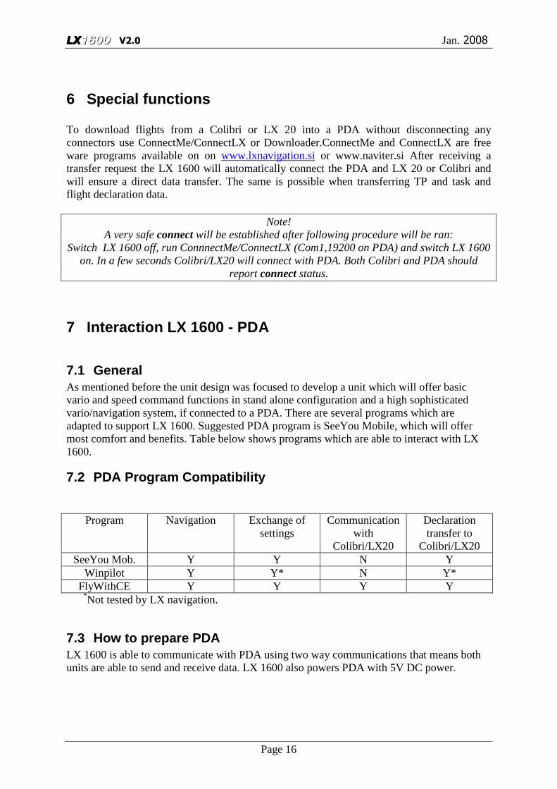
6 Special functions To download flights from a Colibri or LX 20 into a PDA without disconnecting any connectors use ConnectMe/ConnectLX or Downloader.ConnectMe and ConnectLX are free ware programs available on on www.lxnavigation.si or www.naviter.si After receiving a transfer request the LX 1600 will automatically connect the PDA and LX 20 or Colibri and will ensure a direct data transfer. The same is possible when transferring TP and task and flight declaration data.
Note! A very safe connect will be established after following procedure will be ran:
Switch LX 1600 off, run ConnnectMe/ConnectLX (Com1,19200 on PDA) and switch LX 1600 on. In a few seconds Colibri/LX20 will connect with PDA. Both Colibri and PDA should
report connect status.
7 Interaction LX 1600 - PDA
7.1 General As mentioned before the unit design was focused to develop a unit which will offer basic vario and speed command functions in stand alone configuration and a high sophisticated vario/navigation system, if connected to a PDA. There are several programs which are adapted to support LX 1600. Suggested PDA program is SeeYou Mobile, which will offer most comfort and benefits. Table below shows programs which are able to interact with LX 1600.
7.2 PDA Program Compatibility
Program Navigation Exchange of settings
Communication with
Colibri/LX20
Declaration transfer to
Colibri/LX20 SeeYou Mob. Y Y N Y
Winpilot Y Y* N Y* FlyWithCE Y Y Y Y
*Not tested by LX navigation.
7.3 How to prepare PDA LX 1600 is able to communicate with PDA using two way communications that means both units are able to send and receive data. LX 1600 also powers PDA with 5V DC power.

LX1600 V2.0 Jan. 2008
Page 17
7.3.1 COM port setting It is absolutely obligatory to set: COM 1 and 4800,9600,19200,38400bps (depends on GPS that is connected on LX1600. Colibri transmits data on 4800, LXFlarm on 19200) on your PDA, as LX 1600 sends data on same baudrate as it receives from GPS (Colibri or LX flarm). Baudrate is detacted automatically. If no gps is connected on GPS port baudrate is set to 4800bps. Use also PDA manual to arrange this. After mentioned settings are set, PDA should detect incoming NMEA data from LX 1600. Actual baudrate that is detected from GPS, can be checked in last menu of LX1600 (Pressing page up button twice)
Note! A message NO DATA detected, informs that PDA doesn’t receive any data from LX 1600.
Possible reasons: • GPS source (Colibri, LX 20, LX flarm…) not connected to LX 1600 • PDA port isn’t in order: close all other applications, check com 1 and different
baudrates (4800(Colibri), 9600,19200(LX flarm),38400 bps) or simple provide a hard reset of PDA
7.4 Data exchange LX 1600 – PDA This explanation will mostly base on SeeYou Mobile – LX 1600 interaction. Anyhow there will be enough information for the pilots who are using other PDA programs.
7.4.1 Navigation data LX 1600 receives NMEA position data from GPS source which is connected to LX 1600 (Colibri, LX20….). Required data format: NMEA format GGA, RMC 4800, 9600,19200,38400 bps (auto detected) LX 1600 sends toward PDA beside NMEA additionally data sentences including TAS, pressure altitude, serial number... This makes possible that PDA program is able to calculate exact final glide and is also able to calculate wind after using of more methods.
7.4.1.1 Flarm as GPS source Any Flarm unit can be used as GPS data source for LX 1600 having program version 2.10 or higher. It is important that the Flarm unit is sending Navigation and Flarm data at 19200 bps. Both you can adjust after using of Flarm tools and PC. As LX 1600 will recognize Flarm data, those will be also sent toward PDA and PDA will be capable to show traffic situation. See capture 3.4.

LX1600 V2.0 Jan. 2008
Page 18
7.4.2 Exchange of settings As mentioned before LX 1600 and PDA are able to exchange data bidirectional. LX 1600 will send any change happened on LX 1600 (MC,Filter, Ballast and Altitude) directly to PDA without any pilot manipulation. PDA will be automatically updated. Otherwise any change on PDA side will be sent to LX 1600. After using of this principle both units will use the same final glide and sped command data, doesn’t matter on which unit a change has happened.
7.4.2.1 LX 1600 configuration via PDA As you know only MC, Filter, Altitude and Ballast can be manually adjusted on LX 1600. Anyhow LX 1600 offers a wide range of settings which will configure the unit more detailed and this makes LX 1600 extremely flexible. Detailed information you will find in individual PDA program manuals, this explanation is based on LX 1600 – SeeYou Mobile interaction and will help you to understand the materia easily. Some important remark:
• Select device type to LX 1600 on PDA
Setup of LX 1600 (1) -
Function Data direction Vario Filter: will pre set default value in LX 1600 LX 1600 ���� PDA Range: will define vario range of LX 1600 LX 1600 PDA Averager: time adjustment of averager LX 1600 PDA TE Filter: see 3.2 LX 1600 PDA TE level: see 3.2 LX 1600 PDA Smart* LX 1600 PDA Autozero** LX 1600 PDA Speed to fly mode*** LX 1600 PDA

LX1600 V2.0 Jan. 2008
Page 19
Switch style**** LX 1600 PDA TAB ( dead audio area in SC) LX 1600 PDA Spd. change over speed only valid if Auto Speed selected LX 1600 PDA *Smart filter is an additionally filer which is cascaded to the vario filter. This kind of filter will reduce vario needle dynamic. Value 5 will reduce dynamic significant and 0 will not influence at all. **After activation of this function an auto zero procedure of vario and speed signal of LX 1600 will follow. The procedure may be used, if there is suspicion about zero degradation of mentioned signals. The procedure should be carried out exclusively on ground without wind influence. ***LX 1600 offers several ways how to switch over from vario to SC and vice versa. External: the only way is to use external switch mounted usually on the top of the stick. On circling: this selection will arrange change over to SC and vice versa after circling will be detected. Auto speed: change over is based on IAS which is set in Spd. ****Setting open means open switch will change over to SC and setting closed will switch over to SC after the switch will become closed. Taster will react on any change, so a push button may be used.
Example: external switch wiring
Example: push button wring (Taster selection obligatory)
Wire Shield Closed Setting: closed Staus: SC Wire Shield Open Setting: closed Staus: VAR Wire Shield Closed Setting: open Staus: SC Wire Shield Open Setting: open Staus: VAR
Note!
Check WRITE SETTINGS TO EEPROM obligatory. This will store settings permanently into LX 1600 memory and the settings will remain active even during stand alone flight.
SC, marked cable
Shield
Wire
SC, marked cable
Shield
Wire

LX1600 V2.0 Jan. 2008
Page 20
LX 1600 (2) –Audio and LCD indicator settings

LX1600 V2.0 Jan. 2008
Page 21
Two packages of LX 1600 custom settings about audio and LCD vario can be individually set from this page.
Function Data direction Style: 6 audio variants can be used, use TEST* to perform LX 1600 PDA SC Style: defines audio style during SC mode** Freq.: defining of min.,max and zero audio frequency, use TEST LX 1600 PDA SC Volume: audio volume in SC mode, H means more loud in SC LX 1600 PDA LCD indicator: select. regarding to VAR respectively SC, see below LX 1600 PDA *After selection, press OK, return into LX 1600 (2) and press TEST. Execute audio demo exclusively from vario mode. **SC: continuous audio during positive needle deflection. SC neg interrupted audio (piep,piep) during negative needle deflection. There is no SC audio demo, please select during flight.
8 Revision History
02.March 2004 New issued 26.Dec. 2004 Added chapter 5.1 25.Jun 2006 Ch.6 added connect procedure 3.Jan. 2008 Ch.7 added, Ch. 2 and 3 updated
Needle Num#1
Num#2