PILOTS & RELAYS P - Kimray
36
PILOTS & RELAYS P www.kimray.com
Transcript of PILOTS & RELAYS P - Kimray

PILOTS & RELAYS P
www.kimray.com

www.Kimray.com
NOTE: We reserve the right to modify or change, without prior notice, any statement or information contained herein.® Copyright 2020, Kimray, Inc.

www.kimray.com
PILOTS & RELAYSTABLE OF CONTENTS
DIAPHRAGM CONTROLLED HIGH PRESSURE / INDIRECT ACTING: 09:10.1 - 09:10.2 APPLICATIONS: Used to produce a pneumatic output signal when the monitored pressure falls below the set pressure. OPERATING PRESSURE RANGES: 5 psig to 300 psig
DIAPHRAGM CONTROLLED HIGH PRESSURE / DIRECT ACTING: 09:10.3 - 09:10.4 APPLICATIONS: Used to produce a pneumatic output signal when the monitored pressure rises above the set pressure. OPERATING PRESSURE RANGES: 5 psig to 300 psig
DIAPHRAGM CONTROLLED HIGH PRESSURE / DDIFFERENTIAL: 09:10.5 - 09:10.6 APPLICATIONS: Used to produce a pneumatic signal when the differential pressure between two wet or dry pressures is less the the desired setting. OPERATING PRESSURE RANGES: 5 psig to 300 psig
BELLOWS CONTROLLED HIGH PRESSURE / INDIRECT ACTING: 09:20.1 - 09:20.2 APPLICATIONS: Used to produce a pneumatic output signal when the monitored pressure falls below the set pressure. OPERATING PRESSURE RANGES: 75 psig to 2500 psig
BELLOWS CONTROLLED HIGH PRESSURE / DIRECT ACTING: 09:20.1, 09:20.3 APPLICATIONS: Used to produce a pneumatic output signal when the monitored pressure rises above the set pressure. OPERATING PRESSURE RANGES: 75 psig to 2500 psig
DIAPHRAGM CONTROLLED LOW PRESSURE / INDIRECT ACTING: 09:30.1 - 09:30.2 APPLICATIONS: Used to produce a pneumatic output signal when the monitored pressure falls below the set pressure. OPERATING PRESSURE RANGES: .5 ounces to 20 psig
DIAPHRAGM CONTROLLED LOW PRESSURE / DIRECT ACTING: 09:30.3 - 09:30.4 APPLICATIONS: Used to produce a pneumatic output signal when the monitored pressure rises above the set pressure. OPERATING PRESSURE RANGES: .5 ounces to 20 psig
30 VOLUME BOOSTER: 09:40.1 - 09:40.2 APPLICATIONS: Any system in which it is desired to multiply and volume boost a pneumatic signal to a large control valve or similar equipment OPERATING PRESSURE RANGES: 5 psig to 30 psig.
300 VOLUME BOOSTER: 09:50.1 - 09:50.2 APPLICATIONS: Any system in which it is desired to multiply and volume boost a pneumatic signal to a large control valve or similar equipment OPERATING PRESSURE RANGES: 5 psig to 300 psig.
BISTABLE RELAY: 09:60.1 - 09:60.2 APPLICATIONS: Any system where two temporary pressure signals are available One signal to turn “ON” the pilot and one signal to turn “OFF” the pilot. OPERATING PRESSURE RANGES: 20 psig to 30 psig
PRESSURESTAT: 09:70.1 - 09:70.2 APPLICATIONS: used to ressure control of larger steam generators by regulating flow of gas through a motor valve. OPERATING PRESSURE RANGES: 5 psig to 30 psig
ELECTRIC PILOT CONTROLLER: 09:80.1 - 09:70.2 APPLICATIONS: Used in any application where a 4-20mA valve actuator can be controlled by reading a 4-20mA sensor.
PRESSURE DIFFERENTIAL CONTROLLER: 09:90.1 - 09:90.2 APPLICATIONS: Any applications where a constant pressure differential and flow rate is desired. OPERATING PRESSURE RANGES: 0 psig to 2000 psig
DIRECT ACTING PRESSURE SWITCH: 09:100.1 - 09:100.2 APPLICATIONS: Sends a pneumatic signal when the monitored pressure rises above the desired pressure. OPERATING PRESSURE RANGES: 10 psig to 300 psig
TECHNICAL DATA:DIMENSIONS 09:ISEALS/ MATERIAL SPECIFICATIONS 09:II
Issued 10/20 09:00.1

www.kimray.com
PILOTS & RELAYSCODE BUILDERP SERIES (PILOTS)
Series:
P = Pilots & Relays
Model:
DH = Diaphragm Controlled / high pressure Not all selections available on all products listed. See product pages 01:10.1 - 01:10.6 for available optionsAction:
N = Indirect
D = Direct
F = Differential
Shell Material:
D = Ductile Iron
Control Range:
1 = 0 - 300 psig Options: Additional cost and lead times will apply
Service Type: If multiple options required input in sequential order
S = Standard Leave blank if no options required
C = Corrosive 1 = NACE Certification (Corrosive Option Only)
2 = Hydrostatic Test Certification
3 = MTR (Shell Components)
P DH N D 1 S A = AFLAS Elastomer
H = HSN Elastomer
V = FKM Elastomer
X = Export (Hydrostatic test, MTR & 3.1)
Series:
P = Pilots & Relays
Model:
BH = Bellows Controlled / high pressure Not all selections available on all products listed. See product pages 01:20.1 - 01:20.3 for available optionsAction:
N = Indirect
D = Direct
Shell Material:
W = Steel
Control Range:
5 = 75 - 750 psig
6 = 125 - 1500 psig
7 = 200 - 2500 psig Options: Additional cost and lead times will apply
Service Type: If multiple options required input in sequential order
S = Standard Leave blank if no options required
C = Corrosive 1 = NACE Certification (Corrosive Option Only)
2 = Hydrostatic Test Certification
3 = MTR (Shell Components)
P BH N D A S A = AFLAS Elastomer
H = HSN Elastomer
V = FKM Elastomer
X = Export (Hydrostatic test, MTR & 3.1)
09:00.2 Issued 1/21

www.kimray.com
PILOTS & RELAYSCODE BUILDER
P SERIES (PILOTS)
Series:
P = Pilots & Relays
Model:
DL = Diaphragm Controlled / low pressure
Action:
N = Indirect
D = Direct
Shell Material:
D = Ductile Iron
Control Range:
2 = 0 - 20 psig
3 = 0 - 5 psig
4 = 0 - 2.5 psig
Service Type:
S = Standard
C = Corrosive
P DL N S C S
Options: Additional cost and lead times will apply
If multiple options required input in sequential order
Leave blank if no options required
1 = NACE Certification (Corrosive Option Only)
2 = Hydrostatic Test Certification
3 = MTR (Shell Components)
A = AFLAS Elastomer
H = HSN Elastomer
V = FKM Elastomer
X = Export (Hydrostatic test, MTR & 3.1)
Not all selections available on all products listed. See product pages 01:30.1 - 01:30.4 for available options
Issued 1/21 09:00.3

www.kimray.com
PILOTS & RELAYSCODE BUILDERP SERIES (RELAYS)
Series:
P = Pilots & Relays
Model:
VL = 30 Volume Booster
VH = 300 Volume Booster
BR = Bistable Relay
PT = Pressurestat
Action
0 = N/A
Shell Material:
D = Ductile Iron
Control Range:
0 = N/A
Service Type:
S = Standard
C = Corrosive
P VL 0 D 0 S
Options: Additional cost and lead times will apply
If multiple options required input in sequential order
Leave blank if no options required
1 = NACE Certification (Corrosive Option Only)
V = FKM Elastomer
Not all selections available on all products listed. See product pages 01:40.1 - 01:70.2 for available options
09:00.4 Issued 10/20

www.kimray.com
PILOTS & RELAYSDIAPHRAGM CONTROLLED HIGH PRESSURE / INDIRECT ACTING
MODEL DH
All Pictures shown are for illustration purpose only. Actual product may vary due to product enhancement.
APPLICATION: Used to produce a pneumatic output signal when the monitored pressure falls below the set pressure. The pneu-matic source is isolated from the monitored pressure by a vent chamber which allows the monitored pressure to vent away if it reaches a high enough pressure to cause diaphragm failure. The control pilot may be remotely installed to operate a motor valve and function as a pressure reducing regulator. The best application of this pilot is for instrument protection where the monitored pressure may surge above the rated pres-sure of the pilot.
FEATURES: Single Adjustment Filtered gas supply Accurate control Intermittent vent pilot construction Remote installation
CERTIFICATIONS: Canadian Registration Number (CRN): 0C15143.24567890NTY
SUPPLY PRESSURE: Equal to or not less than 60% of maximum upstream pressure when used to operate low pressure control valves. 20-30 psig when used to operate high pressure control valves.
Standard Configuration Code † Order Code Operating Pressure
psigMax. W.P.
psig ††
PDHND1S AHJ 5-300 300
NOTES:For standard & optional seals, metals, Cf Cv values, material specifications & dimensions see technical data on pages 09:I - 09:IV† For Corrosive service remove last "S" & replace with "C"† For code builder see page 09:00.2†† Max W.P. values based on -20°F to 100°F.
Output PressureControlled PressureSupply PressurePilot Diaphragm Assembly
1/4" FNPT
1/4" FNPT
1/4" FNPT
Issued 2/21 09:10.1

www.kimray.com
PILOTS & RELAYSDIAPHRAGM CONTROLLED HIGH PRESSURE / INDIRECT ACTINGMODEL DH DRAWING & PARTS LIST
All Pictures shown are for illustration purpose only. Actual product may vary due to product enhancement.
1
2
3
4
5
6
7
8
9
10
11
15
16
17
13
12
14
18
20
19
15
21
22
23
24
25
26
27
12
29
30
11
6
28
31
7
32
*
*
*
*
*
*
*
* *
*
*
ITEM QTY. DESCRIPTION PART NO ITEM QTY. DESCRIPTION PART NOSTANDARD CORROSIVE STANDARD CORROSIVE
1 1 Base Plate 2607 17 1 Nut 23772 1 Spring 108 108HAC 18 1 Adjusting Screw 5163 5163SS63 1 Gasket 118 19 1 Washer 44914 1 Seat 565 565SS6 20 1 Spring 26115 1 Booster Spring 566 566HAC 21 1 Bonnet 26106 2 Breather Plug 147 147SS6 22 1 Diaphragm Plate 116 116SS67 2 Diaphragm 110 23 1 Diaphragm 5259P8 1 Seat 113 113SS6 24 1 Ring 74379 1 Tee 2000 2000SS6 25 1 Nut 107 107SS6
10 1 Seat Extension 4297 26 1 Spacer Ring 202111 2 Nipple 648 648SS6 27 1 Plug 699 699SS612 2 Housing 1701 28 1 Pilot Plug 11213 1 Gauge 7707 29 1 Filter YAS YASSS614 4 Screw 4298 30 2 Screw 43015 2 Spring Plate 2612 2612SS6 31 1 Mounting Bracket 442816 1 Packing Seal 4488 32 8 Nut 241
* These parts are recommended spare parts and are stocked as repair kits. Repair Kit RSR RSRV
09:10.2 Issued 2/21

www.kimray.com
PILOTS & RELAYSDIAPHRAGM CONTROLLED HIGH PRESSURE / DIRECT ACTING
MODEL DH
All Pictures shown are for illustration purpose only. Actual product may vary due to product enhancement.
APPLICATION: Used to produce a pneumatic output signal when the moni-tored pressure rises above the set pressure. The pneumatic source is isolated from the monitored pressure. The control pilot may be remotely installed to operate a motor valve and function as a pressure reducing regulator.
FEATURES: Single Adjustment Filtered gas supply Accurate control Intermittent vent pilot construction Remote installation
CERTIFICATIONS: Canadian Registration Number (CRN): 0C15143.24567890NTY
SUPPLY PRESSURE: Equal to or not less than 60% of maximum upstream pressure when used to operate low pressure control valves. 20-30 psig when used to operate high pressure control valves.
Output PressureControlled PressureSupply PressurePilot Diaphragm Assembly
1/4" FNPT
1/4" FNPT
Standard Configuration Code † Order Code Operating Pressure
psigMax. W.P.
psig ††
PDHDD1S YIA 10 - 295 300
NOTES:For standard & optional seals, metals, Cf Cv values, material specifications & dimensions see technical data on pages 09:I - 09:IV† For Corrosive service remove last "S" & replace with "C"† For code builder see page 09:00.2†† Max W.P. values based on -20°F to 100°F.
Issued 11/21 09:10.3

www.kimray.com
PILOTS & RELAYSDIAPHRAGM CONTROLLED HIGH PRESSURE / DIRECT ACTINGMODEL DH DRAWING & PARTS LIST
All Pictures shown are for illustration purpose only. Actual product may vary due to product enhancement.
1
2
3
4
5
4
7
8
9
10
11
15
16
17
13
12
14
37
20
19
16
21
22
23
24
25
26
27
32
29
30
33
2
28
31
7
18
6
2
35
36
34
*
*
*
*
*
*
*
*
*
*
*
*
ITEM QTY. DESCRIPTION PART NO ITEM QTY. DESCRIPTION PART NOSTANDARD CORROSIVE STANDARD CORROSIVE
1 1 Base Plate 2607 20 1 Washer 44912 3 Nipple 648 648SS6 21 1 Spring 26113 1 Gasket 118 22 1 Bonnet 26104 2 Tee 2000 2000SS6 23 4 Screw 42985 1 Seat 113 113SS6 24 1 Pivot Screw 2740 2740SS66 1 Booster Spring 566 566HAC 25 1 Gasket 2767 2 Diaphragm 110 110V 26 1 Spacer 50978 1 Connector 874 27 1 Spring 5859 1 Seat 565 565SS6 28 1 Breather Plug 147 147SS6
10 1 Spacer Ring 7437 29 1 Diaphragm 5259P11 1 Tubing 2505SS6 30 1 Nut 107 107SS612 1 Housing 5098 31 1 Housing 170113 1 Gauge 7707 32 1 Plug 699 699SS614 1 Plate 5096 5096SS6 33 1 Pilot Plug 11215 1 Ell 875 34 1 Filter YAS YASSS616 2 Spring Plate 2612 35 2 Screw 43017 1 Packing Seal 4488 36 1 Mounting Bracket 442818 1 Nut 2377 37 8 Nut 24119 1 Adjusting Screw 5163
* These parts are recommended spare parts and are stocked as repair kits. Repair Kit RST RSTV
09:10.4 Issued 3/21
www.kimray.com
PILOTS & RELAYSDIAPHRAGM CONTROLLED HIGH PRESSURE / DIFFERENTIAL
MODEL DH
All Pictures shown are for illustration purpose only. Actual product may vary due to product enhancement.
APPLICATION: Used to produce a pneumatic output signal when the differ-ential pressure between two wet or dry pressures is less the the desired setting. The signal vents when the difference is higher than the setting.
FEATURES: Single Adjustment Filtered gas supply Accurate control Intermittent vent pilot construction Remote installation
CERTIFICATIONS: Canadian Registration Number (CRN): 0C15143.24567890NTY
SUPPLY PRESSURE: Equal to or not less than 60% of maximum upstream pressure when used to operate low pressure control valves. 20-30 psig when used to operate high pressure control valves.
Pilot Diaphragm AssemblySupply PressureUpstream PressureDownstream PressureOutput Pressure
1/4" FNPT
1/4" FNPT
1/4" FNPT
Standard Configuration Code † Order Code Operating Pressure
psigMax. W.P.
psig ††
PDHFD1S AHP 5-300 300
NOTES:For standard & optional seals, metals, Cf Cv values, material specifications & dimensions see technical data on pages 09:I - 09:IV† For Corrosive service remove last "S" & replace with "C"† For code builder see page 09:00.2†† Max W.P. values based on -20°F to 100°F.
Issued 2/21 09:10.5

www.kimray.com
PILOTS & RELAYSDIAPHRAGM CONTROLLED HIGH PRESSURE / DIFFERENTIALMODEL DH DRAWING & PARTS LIST
All Pictures shown are for illustration purpose only. Actual product may vary due to product enhancement.
1
2
3
4
5
6
7
8
9
10
11
15
16
18
13
12
14
32
20
19
16
21
22
23
24
25
26
27
29
30
25
7
28
31
17
8
ITEM QTY. DESCRIPTION PART NO ITEM QTY. DESCRIPTION PART NOSTANDARD CORROSIVE STANDARD CORROSIVE
1 1 Base Plate 2607 17 1 Packing Seal 44882 1 Spring 108 108HAC 18 1 Nut 23773 1 Gasket 118 19 1 Adjusting Screw 51634 1 Seat 565 565SS6 20 1 Washer 44915 1 Booster Spring 566 566HAC 21 1 Spring 26116 1 Tee 2000 2000SS6 22 1 Bonnet 26107 2 Diaphragm 110 110V 23 1 Pivot Screw 20208 2 Nipple 648 648SS6 24 1 Spacer Ring 20219 1 Seat 113 113SS6 25 2 Housing 1701
10 1 Nut 107 107SS6 26 1 Ring 743711 1 Diaphragm 5259P 5259V 27 1 Pilot Plug 11212 1 Diaphragm Plate 2022 2022SS6 28 1 Plug 699 699SS613 1 Gauge 7707 29 1 Filter YAS YASSS614 1 Breather Plug 147 30 2 Screw 43015 4 Screw 4298 31 1 Mounting Bracket 442816 2 Spring Plate 2612 32 8 Nut 241
* These parts are recommended spare parts and are stocked as repair kits. Repair Kit RSR RSRV
*
*
*
*
*
*
*
*
*
*
*
09:10.6 Issued 10/21
www.kimray.com
PILOTS & RELAYSBELLOWS CONTROLLED HIGH PRESSURE
MODEL BH
All Pictures shown are for illustration purpose only. Actual product may vary due to product enhancement.
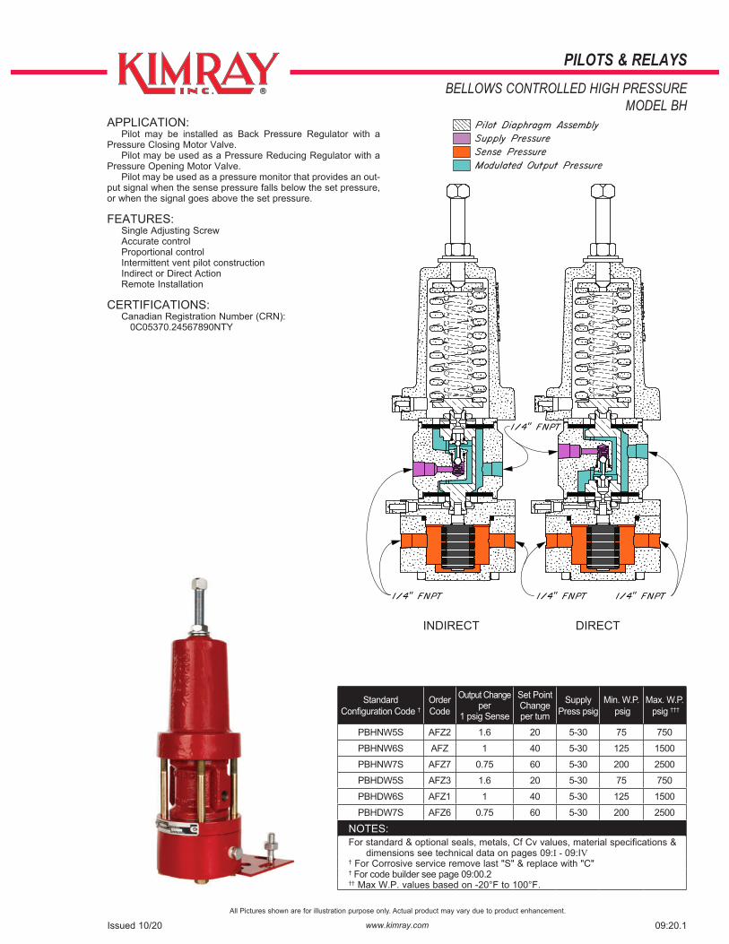
APPLICATION: Pilot may be installed as Back Pressure Regulator with a Pressure Closing Motor Valve. Pilot may be used as a Pressure Reducing Regulator with a Pressure Opening Motor Valve. Pilot may be used as a pressure monitor that provides an out-put signal when the sense pressure falls below the set pressure, or when the signal goes above the set pressure.
FEATURES: Single Adjusting Screw Accurate control Proportional control Intermittent vent pilot construction Indirect or Direct Action Remote Installation
CERTIFICATIONS: Canadian Registration Number (CRN): 0C05370.24567890NTY
Standard Configuration Code †
Order Code
Output Change per
1 psig Sense
Set Point Change per turn
Supply Press psig
Min. W.P. psig
Max. W.P. psig †††
PBHNW5S AFZ2 1.6 20 5-30 75 750
PBHNW6S AFZ 1 40 5-30 125 1500
PBHNW7S AFZ7 0.75 60 5-30 200 2500
PBHDW5S AFZ3 1.6 20 5-30 75 750
PBHDW6S AFZ1 1 40 5-30 125 1500
PBHDW7S AFZ6 0.75 60 5-30 200 2500
NOTES:For standard & optional seals, metals, Cf Cv values, material specifications & dimensions see technical data on pages 09:I - 09:IV† For Corrosive service remove last "S" & replace with "C"† For code builder see page 09:00.2†† Max W.P. values based on -20°F to 100°F.
Modulated Output PressureSense PressureSupply PressurePilot Diaphragm Assembly
1/4" FNPT1/4" FNPT 1/4" FNPT
1/4" FNPT
INDIRECT DIRECT
Issued 10/20 09:20.1

www.kimray.com
PILOTS & RELAYSBELLOWS CONTROLLED HIGH PRESSUREMODEL BH DRAWING
All Pictures shown are for illustration purpose only. Actual product may vary due to product enhancement.
1
2
3
4
5
6
7
8
9
10
11
15
16
18
13
12
14
20
19
21
22
23
24
25
17
32
33
26
27
29
30
34
7
28
31
7
26
32
33
29
30
28
31
10
13
26
27
7
7
26
11
12
14
INDIRECT
DIRECT
09:20.2 Issued 10/20

www.kimray.com
PILOTS & RELAYSPILOTS
MODEL BH PARTS LIST
ITEM QTY. DESCRIPTION PART NOSTANDARD CORROSIVE
1 4 Screw 44272 2 Nut 2413 1 Mounting Bracket 44284 2 Screw 4305 1 Main Body 4429 4429S6
6 1 Bellows Assembly750 psig 51481500 psig 44202500 psig 6521
7 3 O-Ring 265 265V8 1 O-Ring 802 802V9 1 Breather Plug 1357 1357SS610 1 Diaphragm Plate 4434SS611 1 Diaphragm 4447 4447V12 1 Supply Body 4451 4451SS613 1 Seat Housing 4440 4440SS614 1 Diaphragm 4436 4436V15 1 Breather Plug 147 147SS616 1 Diaphragm Plate 4441SS617 1 Lower Spring Plate 4443SS618 1 Bonnet 445019 1 Spring (2500 psig Only) 652220 1 Spring 444821 1 Upper Spring Plate 4444 4444SS622 1 Packing Seal 448823 1 Washer 449124 1 Nut 2377 2377SS625 1 Adjusting Screw 4446 4446SS626 1 Diaphragm Nut 4433 4433SS627 1 Diaphragm Spacer 4442SS628 1 Seat 113 113SS629 1 Pilot Plug 112 112SS630 1 Seat 565 565SS631 1 Spring 108 108HAC32 1 Stem 4435SS633 1 Diaphragm Spacer 4432SS634 1 Lower Housing 4431 4431SS6
Not Shown Gauge750 psig w.p. 77081500 psig w.p. 77092500 psig w.p. 7710
Not Shown Plug 699 699SS6Repair Kit RBQ RBQV
* These parts are recommended spare parts and are stocked as repair kits.
*
*
*
*
*
*
*
*
*
*
Issued 3/21 09:20.3

www.kimray.com
Kimray is an ISO 9001- certified manufacturer.
NOTES:

www.kimray.com
PILOTS & RELAYSDIAPHRAGM CONTROLLED LOW PRESSURE / INDIRECT ACTING
MODEL DL
All Pictures shown are for illustration purpose only. Actual product may vary due to product enhancement.
APPLICATION: Pilot may be installed remotely from the control valve.The Pilot is used in the control of low pressure where the desired controlled pressure ranges from a few ounces to 20 psig on: Vessels Vent lines Distribution systems Inlet and recirculation on compressors, pressure
It may be used to produce a pneumatic output signal when the monitored pressure falls below the set pressure. The pneumatic signal source is isolated from the monitored pressure.
FEATURES: Single adjustment Filtered gas supply High accuracy Intermittent vent pilot construction Remote installation
SUPPLY PRESSURE: Equal to or not less than 60% of maximum upstream pressure when used to operate low pressure control valves. 20-30 psig when used to operate high pressure control valves.
Diaphragm AssemblySupply PressureControlled PressureOutput Pressure
1" FNPT 1/4" FNPT
1/4" FNPT
1/4" FNPT
Standard Configuration Code † Order Code Operating Pressure Max. W.P.
psig ††
PDLND2S AHK2.5 .5 oz - 2.5 psig
175PDLND3S AHK5 1 oz - 5 psig
PDLND4S AHK20 1 psig - 20 psig
NOTES:For standard & optional seals, metals, Cf Cv values, material specifications & dimensions see technical data on pages 09:I - 09:IV† For Corrosive service remove last "S" & replace with "C"† For code builder see page 09:00.3†† Max W.P. values based on -20°F to 100°F.
Issued 2/21 09:30.1

www.kimray.com
PILOTS & RELAYS
ITEM QTY. DESCRIPTION PART NO ITEM QTY. DESCRIPTION PART NOSTANDARD CORROSIVE STANDARD CORROSIVE
1 1 Gasket 118 17 1 Nut 9222 16 Nut 241 18 1 Adjusting Screw 8973 1 Seat 565 565SS6 19 6 Screw 75314 1 Stem 2913 2913SS6 20 1 Gasket 12165 4 Screw 191 21 1 Upper Diaphragm Plate 1208 1208SS66 4 Gasket 242 22 1 Pilot Seat 113 113SS67 1 Nipple 648 648SS6 23 1 Diaphragm 1108 1 Tee 219 219SS6 24 1 Upper Housing 12069 1 Lower Diaphragm plate 1340 1340SS6 25 1 Diaphragm 1212
10 1 Gauge 7704 26 1 Vent Plug 14711 10 Screw 236 27 1 Lower Housing 135612 1 O-Ring 265 28 1 Plug 699 699SS613 1 Diaphragm Nut 2912 29 1 Nipple 75 75SS6
14 1 Spring20 lbs. (standard) 4379 30 1 Filter YAS YASSS65 lbs. (optional) 3061 31 2 Bolt 4302.5 lbs. (optional) 1527 32 1 Mount Bracket 4428
15 1 Spring Plate
20 lbs. (standard) 7148S6 33 1 Spring 566 566HAC5 lbs. (optional) 636SS6 34 1 Pilot Plug 1122.5 lbs. (optional) 35 1 Spring 1360 1360SS6
16 1 Bonnet 1336 36 1 Base Plate 962S* These parts are recommended spare parts and are stocked as repair kits. Repair Kit RWO RWOV
DIAPHRAGM CONTROLLED LOW PRESSURE / INDIRECT ACTINGMODEL DL DRAWING & PARTS LIST
All Pictures shown are for illustration purpose only. Actual product may vary due to product enhancement.
1
2
3
4
5
6
7
8
9
10
11
15
16
17
13
12
14
18
20
19
21
22
23
24
25
26
27
28
29
30
31
32
33
34
35
36
*
*
*
*
*
*
*
*
*
*
*
09:30.2 Issued 3/21

www.kimray.com
PILOTS & RELAYSDIAPHRAGM CONTROLLED LOW PRESSURE / DIRECT ACTING
MODEL DL
All Pictures shown are for illustration purpose only. Actual product may vary due to product enhancement.
APPLICATION: Pilot may be installed remotely from the control valve.The Pilot is used in the control of low pressure where the desired controlled pressure ranges from a few ounces to 20 psig on: Vessels Vent lines Distribution systems Inlet and recirculation on compressors, pressure
Used to produce a proportional pneumatic output signal when the monitored pressure rises above the set pressure. The pneumatic signal source is isolated from the monitored pressure.
FEATURES: Single adjustment Filtered gas supply High accuracy Intermittent vent pilot construction Remote installation
SUPPLY PRESSURE: Equal to or not less than 60% of maximum upstream pressure when used to operate low pressure control valves. 20-30 psig when used to operate high pressure control valves.
Diaphragm AssemblySupply PressureControlled PressureOutput Pressure
1" FNPT 1/4" FNPT
1/4" FNPT
1/4" FNPT
Standard Configuration Code † Order Code Operating Pressure Max. W.P.
psig ††
PDLDD2S YIB2.5 .5 oz - 2.5 psig
175PDLDD3S YIB5 1 oz - 5 psig
PDLDD4S YIB20 1 psig - 20 psig
NOTES:For standard & optional seals, metals, Cf Cv values, material specifications & dimensions see technical data on pages 09:I - 09:IV† For Corrosive service remove last "S" & replace with "C"† For code builder see page 09:00.3†† Max W.P. values based on -20°F to 100°F.
Issued 2/21 09:30.3
www.kimray.com
PILOTS & RELAYS
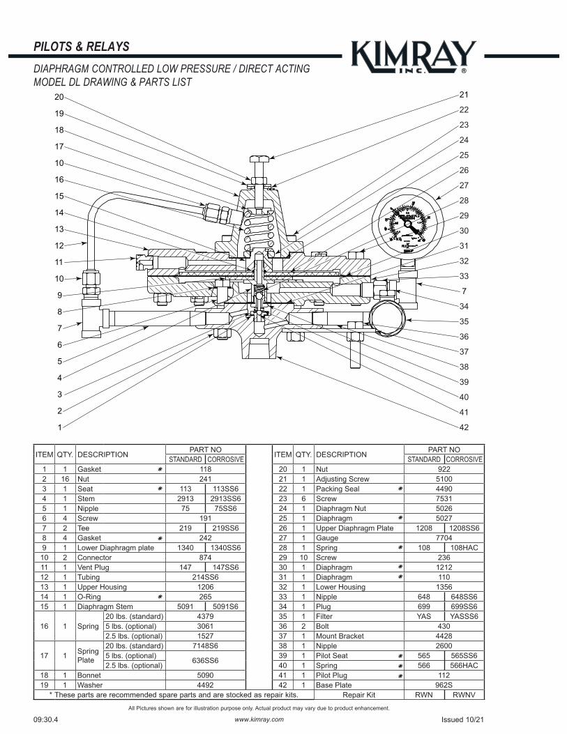
ITEM QTY. DESCRIPTION PART NO ITEM QTY. DESCRIPTION PART NOSTANDARD CORROSIVE STANDARD CORROSIVE
1 1 Gasket 118 20 1 Nut 9222 16 Nut 241 21 1 Adjusting Screw 51003 1 Seat 113 113SS6 22 1 Packing Seal 44904 1 Stem 2913 2913SS6 23 6 Screw 75315 1 Nipple 75 75SS6 24 1 Diaphragm Nut 50266 4 Screw 191 25 1 Diaphragm 50277 2 Tee 219 219SS6 26 1 Upper Diaphragm Plate 1208 1208SS68 4 Gasket 242 27 1 Gauge 77049 1 Lower Diaphragm plate 1340 1340SS6 28 1 Spring 108 108HAC
10 2 Connector 874 29 10 Screw 23611 1 Vent Plug 147 147SS6 30 1 Diaphragm 121212 1 Tubing 214SS6 31 1 Diaphragm 11013 1 Upper Housing 1206 32 1 Lower Housing 135614 1 O-Ring 265 33 1 Nipple 648 648SS615 1 Diaphragm Stem 5091 5091S6 34 1 Plug 699 699SS6
16 1 Spring20 lbs. (standard) 4379 35 1 Filter YAS YASSS65 lbs. (optional) 3061 36 2 Bolt 4302.5 lbs. (optional) 1527 37 1 Mount Bracket 4428
17 1 Spring Plate
20 lbs. (standard) 7148S6 38 1 Nipple 26005 lbs. (optional) 636SS6 39 1 Pilot Seat 565 565SS62.5 lbs. (optional) 40 1 Spring 566 566HAC
18 1 Bonnet 5090 41 1 Pilot Plug 11219 1 Washer 4492 42 1 Base Plate 962S
* These parts are recommended spare parts and are stocked as repair kits. Repair Kit RWN RWNV
DIAPHRAGM CONTROLLED LOW PRESSURE / DIRECT ACTINGMODEL DL DRAWING & PARTS LIST
All Pictures shown are for illustration purpose only. Actual product may vary due to product enhancement.
1
2
3
4
5
6
7
8
9
10
11
15
16
17
13
12
14
18
20
19
10
21
22
23
24
25
26
27
28
29
30
31
32
33
34
35
36
7
37
38
39
40
41
42
*
*
*
*
*
*
*
*
*
*
*
*
09:30.4 Issued 10/21

www.kimray.com
PILOTS & RELAYS30 VOLUME BOOSTER
MODEL VL
All Pictures shown are for illustration purpose only. Actual product may vary due to product enhancement.
APPLICATION: Any system in which it is desired to multiply and volume boost a pneumatic signal to a large control valve or similar equipment. Amplification of the input pneumatic signal is approximately 4:1. When manual rest is used, it can monitor a 3 way valve and vent system supply if a preset limit is exceeded
FEATURES: Field reversible for direct throttle or indirect snap action Optional manual reset lever when Direct Acting Provides “tattle-tell” signal when preset limit is exceeded Intermittent vent pilot 3 Way Valving Rapid venting action No dead center
Standard Configuration Code †
Order Code
Variable Press psig ††
Supply Press psig
Output Press psig
Max. W.P. psig †††
PVL0D0S YAF 0 - 30 5 - 30 0 or Supply 30
NOTES:For standard & optional seals, metals, Cf Cv values, material specifications & dimensions see technical data on pages 09:I - 09:IV† For Corrosive service remove last "S" & replace with "C"† For code builder see page 09:00.4†† Variable pressure snapping range depending on supply Pressure approximately 2 - 7 psig at 30 psig††† Max W.P. values based on -20°F to 100°F.
1 15
/32"
2 3
/32"
3/4"
1 9/32"
Diaphragm AssemblySupply PressureVariable PressureOutput Pressure
1/4" FNPT
1/4" FNPT
Optional Reset Lever
1/4" FNPT
1/4" FNPT
Issued 10/20 09:40.1

www.kimray.com
PILOTS & RELAYS30 VOLUME BOOSTERMODEL VL DRAWING & PARTS LIST
All Pictures shown are for illustration purpose only. Actual product may vary due to product enhancement.
1
2
3
4
5
6
7
8
9
10
11
15
16
17
13
12
14
18
20
19
21
ITEM QTY. DESCRIPTION PART NO ITEM QTY. DESCRIPTION PART NOSTANDARD CORROSIVE STANDARD CORROSIVE
1 1 Spring 585 11 1 Cover 577 2414SS62 1 Plug 699 699SS6 12 1 Upper Diaphragm 583HSN3 1 Gasket 118 13 1 Spool 580 580SS64 1 Spring 566 566HAC 14 1 Spring 108 108HAC5 1 Lower Diaphragm 584HSN 15 1 Bushing 539 539SS66 1 Breather Plug 147 147SS6 16 1 Reset Lever 13967 1 Diaphragm Plate 579 579SS6 17 1 Spacer 581 581SS6
8 1 Housing 578 578SS6 18 1 Seat 113 113SS6Optional Vented Housing 5365 19 1 Seat 565 565SS6
9 1 Diaphragm 582HSN 20 1 Pilot Plug 11210 6 Screw 573 21 1 Body 587 2408SS6
* These parts are recommended spare parts and are stocked as repair kits. Repair Kit RXY
* *
*
*
*
*
*
* *
*
09:40.2 Issued 10/20

www.kimray.com
PILOTS & RELAYS300 VOLUME BOOSTER
MODEL VH
All Pictures shown are for illustration purpose only. Actual product may vary due to product enhancement.
APPLICATION: Any system where a 0 to 300 psig signal must be switched using a 20 to 30 psig signal.
FEATURES: Intermittent vent pilot 3 Way Valving Direct acting
Standard Configuration Code †
Order Code
Variable Press psig ††
Supply Press psig
Output Press psig
Max. W.P. psig †††
PVH0D0S YAI 20 - 30 0 - 300 0 or Supply 300
NOTES:For standard & optional seals, metals, Cf Cv values, material specifications & dimensions see technical data on pages 09:I - 09:IV† For Corrosive service remove last "S" & replace with "C"† For code builder see page 09:00.4†† Variable pressure snapping range depending on supply Pressure approximately 2 - 7 psig at 30 psig††† Max W.P. values based on -20°F to 100°F.
1 13
/32"
2 1/16
"
3/4"
1 9/32"
1/4" FNPT
1/4" FNPT
Diaphragm AssemblySupply PressureVariable PressureOutput Pressure
Issued 10/20 09:50.1

www.kimray.com
PILOTS & RELAYS300 VOLUME BOOSTERMODEL VH DRAWING & PARTS LIST
All Pictures shown are for illustration purpose only. Actual product may vary due to product enhancement.
1
2
3
4
5
6
7 8
9
10
11
13
12
14
ITEM QTY. DESCRIPTION PART NO ITEM QTY. DESCRIPTION PART NOSTANDARD CORROSIVE STANDARD CORROSIVE
1 1 Spring 585 8 1 Cover 577 2414SS62 1 O-Ring 265HSN 9 1 Diaphragm 582HSN3 1 O-Ring 924HSN 10 1 Housing 51254 1 O-Ring 638HSN 11 1 Spring 13585 1 Breather Plug 147 147SS6 12 1 Lower Seat 2338 2338S66 1 Upper Seat 2337 2337S6 13 1 Pilot Plug 1127 6 Screw 573 14 1 Body 2335 2408SS6
* These parts are recommended spare parts and are stocked as repair kits. Repair Kit RXY
*
**
*
*
*
09:50.2 Issued 10/20

www.kimray.com
PILOTS & RELAYSBISTABLE PILOT
MODEL BR
All Pictures shown are for illustration purpose only. Actual product may vary due to product enhancement.
APPLICATION: Any system where two temporary pressure signals are avail-able. One sighal to turn “ON” the pilot and one signal to turn “OFF” the pilot.
FEATURES: Bistable operation Temporary signal will turn “ON” or “OFF” Intermittent vent pilot Semi-snap action
Standard Configuration Code †
Order Code
On/Off Signal
Supply Press psig
Output Press psig
Max. W.P. psig ††
PBR0D0S YAH1 20 - 30 20 - 30 0 or Supply 30
NOTES:For standard & optional seals, metals, Cf Cv values, material specifications & dimensions see technical data on pages 09:I - 09:IV† For Corrosive service remove last "S" & replace with "C"† For code builder see page 09:00.4†† Max W.P. values based on -20°F to 100°F.
Diaphragm AssemblySupply PressureOn SignalOff SignalOutput Pressure
1 15
/32"
2 5
/32"
3/4"
1 1/
4"
1/4" FNPT
1/4" FNPT
1/4" FNPT
Issued 3/21 09:60.1

www.kimray.com
PILOTS & RELAYSBISTABLE PILOTMODEL BR DRAWING & PARTS LIST
All Pictures shown are for illustration purpose only. Actual product may vary due to product enhancement.
ITEM QTY. DESCRIPTION PART NO ITEM QTY. DESCRIPTION PART NOSTANDARD CORROSIVE STANDARD CORROSIVE
1 1 Spring 585 12 1 Screw 2670SS62 1 Plug 699 13 1 Diaphragm 896HSN3 1 Gasket 118 14 1 O-Ring 569HSN4 1 Diaphragm 2619 15 1 Jumper Tube 895 895SS65 1 Spool 2616 2616SS6 16 1 Spacer 581 581SS66 1 Diaphragm 583HSN 17 1 Seat 113 113SS67 1 Lower Diaph. Plate 857 857SS6 18 1 Seat 565 565SS68 1 Housing 2617 2617SS6 19 1 Breather Plug 1479 1 Upper Diaph. Plate 2618 2618SS6 20 1 Pilot Plug 112
10 6 Screw 573 21 1 Body 2615 2615SS611 1 Cover 2620 2620SS6 Repair Kit RXY
* These parts are recommended spare parts and are stocked as repair kits.
1
2
3
4
5
6
7
8
9
10
11
15
16
17
13
12
14
18
20
19
21
*
*
*
*
*
*
*
*
*
09:60.2 Issued 3/21

www.kimray.com
PILOTS & RELAYSPRESSURESTAT
MODEL PT
All Pictures shown are for illustration purpose only. Actual product may vary due to product enhancement.
APPLICATION: Direct firing of small steam generators by controlling flow of gas through the pilot to the burner. Approximate capacity of pilot is 360 SCFH with 15 psig supply pressure. Pressure control of larger steam generators by regulating flow of gas through a control valve.
FEATURES: Intermittent vent pilot Reverse acting Throttle action Adjustable Steam Pressure
Standard Configuration Code †
Order Code
Max. Steam Press psig
Max. Steam Temp.
Supply Press psig
Output Press psig ††
Max. W.P. psig †††
PPT0D0S YAA 15 250° F 5 - 30 0 - 20 30
NOTES:For standard & optional seals, metals, Cf Cv values, material specifications & dimensions see technical data on pages 09:I - 09:IV† For Corrosive service remove last "S" & replace with "C"† For code builder see page 09:00.4†† Adjustable Steam Pressure††† Max W.P. values based on -20°F to 100°F.
3"
3 11/
16"
3/4"
1 9/32"
1/4" FNPT1/4" FNPT
2 13/16"
Diaphragm AssemblySupply PressureOutput PressureSteam Pressure
Issued 10/20 09:70.1

www.kimray.com
PILOTS & RELAYSPRESSURESTATMODEL PT DRAWING & PARTS LIST
All Pictures shown are for illustration purpose only. Actual product may vary due to product enhancement.
1
2
3
4
5
6
7
8
9
10
11
15
16
17
13
12
14
18
20
19
26
25
24
23
22
21
ITEM QTY. DESCRIPTION PART NO ITEM QTY. DESCRIPTION PART NOSTANDARD CORROSIVE STANDARD CORROSIVE
1 1 Spring 585 14 1 Adjustment Screw 8972 1 Plug 699 699HSN 15 1 Jamb Nut 9223 1 Gasket 118 16 1 Spring Plate 636SS64 1 Lower Diaphragm 584HSN 17 1 Screw 8985 1 Spool 580 580SS6 18 1 Lower Diaphragm Plate 857 857SS66 1 Diaphragm 583HSN 19 1 Housing 9477 1 O-Ring 569HSN 20 1 Spacer 581 581SS68 1 Jumper Tube 895 895SS6 21 1 Breather Plug 147 147SS69 1 Upper Diaphragm 896HSN 22 1 Seat 113 113SS6
10 6 Screw 573 23 1 Spring 566 566HAC11 1 Upper Diaphragm Plate 893 24 1 Seat 565 565SS6
12 1 Standard Heavy Spring 692 25 1 Pilot Plug 112Optional Light Spring 86 26 1 Body 894
13 1 Bonnet 856 Repair Kit RXY* These parts are recommended spare parts and are stocked as repair kits.
*
*
*
*
*
*
*
*
*
*
09:70.2 Issued 10/20

www.kimray.com
PILOTS & RELAYSELECTRIC PILOT CONTROLLER
All Pictures shown are for illustration purpose only. Actual product may vary due to product enhancement.
APPLICATION: The Electronic Pilot Controller is used in any application where a 4-20mA valve actuator can be controlled by reading a 4-20mA sensor.
FEATURES Multiple control schemes * PID Control (Pressure Reducing or Back Pressure) * High Limit shutdown * Low Limit shutdown *GAP Control (example: plunger lift application) * High Low shutdown Multiple applications * Pressure control * Flow control * Temperature control * Level control Powered from actuator supply Reverse Battery Protection Bright OLED display technology User-friendly menus for installation/operation PID Autotuning available for ease of installation
CONSTRUCTION: Cast aluminum housing for hazardous location areas.
OPERATION: The Electronic Pilot receives an analog (4-20mA) signal from a sensor which measures a process valve. The signal is condi-tioned and sent to an electronically controlled valve via 4-20mA output signal. A PID control loop is utilized along with auto-tune and manual tuning capabilities. The pilot can connect directly to an electric actuator and share a common input power source.
INSTALLATION AND COMMISSION:1) Mount appropriate hardware2) Specify sensor using the menu3) Select control scheme 4) Perform auto-tuning or manual-tuning
CERTIFICATIONS: CSA HAZARDOUS LOCATION Class I, Div 1, Groups B, C, D Class II, Groups E, F, G Class III, T6 Type 4X enclosure, IP66 rated
Order Code Description
YEP ELECTRIC PILOT CONTROLLER
ELECTRICAL RATINGSMin Max Units
Input Voltage (VIN) 10 30 VDCInput Current 0.05 0.10 ADC
Ambient Temperature-40 60 °C-40 140 °F
Analog input From Sensor 4-20 mA (powered by VIN)Discrete input Dry Contacts onlyAnalog Output to Actuator 4-20 mA (powered by VIN)Communications RS-485 (MODBUS RTU)Discrete Output 0 VDC or VIN, up to 1A
Flow
Flow
BACK PRESSURE INSTALLATION
PRESSURE REDUCING INSTALLATION
Issued 10/20 09:80.1

www.kimray.com
PILOTS & RELAYSELECTRIC PILOT CONTROLLERDRAWING & PARTS LIST
All Pictures shown are for illustration purpose only. Actual product may vary due to product enhancement.
4 1/2" 3 7/8"
4 7/
8"Ø4"
123
4
5
6
ITEM QTY. DESCRIPTION PART NO1 4 SET SCREW 6-32 7472A2 4 PCB STANDOFF 6-32 x 3/8" HEX 7472B3 4 6-32 x 1/4 SOCKET HEAD SCREW 74954 1 MAIN PCB KA75095 1 ENCLOSURE 74836 1 PRESSURE TRANSDUCER SEE BELOW
ACCESSORIES AVAILABLEPART NO PRESSURE RANGE DESCRIPTION
KSGS100PG 0-100 psig PRESSURE TRANSDUCERKSGS300PG 0-300 psig PRESSURE TRANSDUCERKSGS750PG 0-750 psig PRESSURE TRANSDUCERKSGS20CPS 0-2000 psig PRESSURE TRANSDUCERKSGS40CPS 0-4000 psig PRESSURE TRANSDUCERKSGS60CPS 0-6000 psig PRESSURE TRANSDUCER
7513 1/2 NPT CONDUIT PLUG
09:80.2 Issued 3/21
www.kimray.com
PILOTS & RELAYSDIRECT ACTING PRESSURE SWITCH
All Pictures shown are for illustration purpose only. Actual product may vary due to product enhancement.
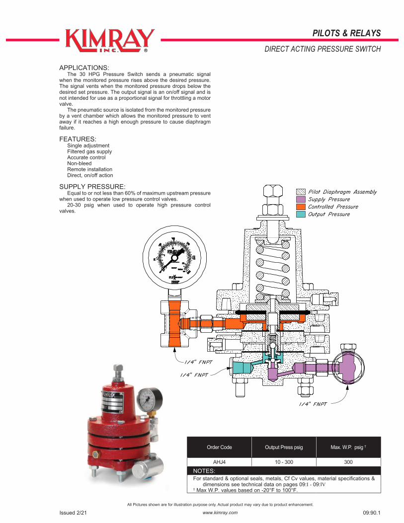
APPLICATIONS: The 30 HPG Pressure Switch sends a pneumatic signal when the monitored pressure rises above the desired pressure. The signal vents when the monitored pressure drops below the desired set pressure. The output signal is an on/off signal and is not intended for use as a proportional signal for throttling a motor valve. The pneumatic source is isolated from the monitored pressure by a vent chamber which allows the monitored pressure to vent away if it reaches a high enough pressure to cause diaphragm failure.
FEATURES: Single adjustment Filtered gas supply Accurate control Non-bleed Remote installation Direct, on/off action
SUPPLY PRESSURE: Equal to or not less than 60% of maximum upstream pressure when used to operate low pressure control valves. 20-30 psig when used to operate high pressure control valves.
Order Code Output Press psig Max. W.P. psig †
AHJ4 10 - 300 300
NOTES:For standard & optional seals, metals, Cf Cv values, material specifications & dimensions see technical data on pages 09:I - 09:IV† Max W.P. values based on -20°F to 100°F.
1/4" FNPT
1/4" FNPT
1/4" FNPT
Output PressureControlled PressureSupply PressurePilot Diaphragm Assembly
Issued 2/21 09:90.1

www.kimray.com
PILOTS & RELAYS
ITEM QTY. DESCRIPTION PART NO ITEM QTY. DESCRIPTION PART NOSTANDARD CORROSIVE STANDARD CORROSIVE
1 1 Base Plate 2607 17 1 Nut 23772 1 Gasket 118 18 1 Adjusting Screw 5163 5163SS63 1 Seat 113 113SS6 19 1 Washer 44914 1 Booster Spring 566 566HAC 20 1 Spring 26115 2 Breather Plug 147 147SS6 21 1 Bonnet 26106 2 Diaphragm 110 22 1 Diaphragm Plate 116 116SS67 1 Seat 565 565SS6 23 1 Diaphragm 5259P8 1 Tee 2000 2000SS6 24 1 Ring 74379 1 Seat Extension 4297 25 1 Nut 107 107SS6
10 2 Nipple 648 648SS6 26 1 Spacer Ring 202111 2 Housing 1701 27 1 Pilot Plug 11212 1 Spring 585 28 1 Plug 699 699SS613 1 Gauge 7707 29 1 Filter YAS YASSS614 4 Screw 4298 30 2 Screw 43015 2 Spring Plate 2612 2612SS6 31 1 Mounting Bracket 442816 1 Packing Seal 4488 32 8 Nut 241
* These parts are recommended spare parts and are stocked as repair kits. Repair Kit RSR RSRV
DIRECT ACTING PRESSURE SWITCHDRAWING & PARTS LIST
All Pictures shown are for illustration purpose only. Actual product may vary due to product enhancement.
1
2
3
4
5
6
7
8
9
10
6
15
16
17
13
12
14
18
20
19
15
21
22
23
24
25
26
11
27
29
30
10
5
28
31
11
32
*
*
*
*
*
*
*
* *
*
*
09:90.2 Issued 2/21

www.kimray.com
PILOTS & RELAYSPRESSURE DIFFERENTIAL CONTROLLER
All Pictures shown are for illustration purpose only. Actual product may vary due to product enhancement.
APPLICATION: The “PDC” Series Pressure Differential Controller connects across the orifice plate of a meter run to maintain a constant sta-ble pressure differential across the meter run. This relates to a constant flow rate when the upstream pressure is constant. This pilot adjusts the flow rate to maintain the pressure differential by positioning a pressure opening motor valve that has character-ized equal percentage valve trim for precise flow control. Precise gas flow rate for gas lift. Pressure differential control across orifice plates for better charts and measurement of gas flow. Stabilizes gas flow for better well production. Pressure differential limiting for reducing “off chart” condi-tions. Any applications where a constant pressure differential and flow rate is desired.
FEATURES: Intermittent vent pilot Throttle operation 1 to 260 inches of water differential pressure Heavier springs available, if specified May be used with any type of diaphragm motor valve
Order Code Supply Press psig Output Press psig Max. W.P. psig †
FAB2 5 - 30 Variable, 2 - 30 2000
NOTES:For standard & optional seals, metals, Cf Cv values, material specifications & dimensions see technical data on pages 09:I - 09:IV† Max W.P. values based on -20°F to 100°F.
Main Diaphragm Assembly3PTC Pilot Diaphragm AssemblyUpstream PressureDownstream PressureSupply PressureDiaphragm Pressure
1/4" FNPT
1/4" FNPT
1" FNPT
Issued 2/21 09:100.1

www.kimray.com
PILOTS & RELAYSPRESSURE DIFFERENTIAL CONTROLLERDRAWING & PARTS LIST
All Pictures shown are for illustration purpose only. Actual product may vary due to product enhancement.
22
21
23
1 2 3 4 5 6 7 8 9 10 11 15 16 171312 14 18 2019
262524 27 28 29 30 31 32 33 34 38 39 403635 37 41
ITEM QTY. DESCRIPTION PART NO ITEM QTY. DESCRIPTION PART NO1 2 Stud 3/4-10 x 4.5 83A 26 1 Spring 40782 1 O-Ring 87 27 2 Diaphragm Plate 893 1 Upper Flange 93 28 1 Diaphragm 6414 16 Nut 82B 29 1 Packing Gland Assembly 6465 1 Spring 1527 30 6 Stud 3/4-10 x 4.0 82A6 1 Nut 637 31 1 Pilot Cap 9697 1 Spring Plate 4125 32 1 Waggle Arm 944S68 1 Screw 264 33 1 Pivot Bar 6449 1 Knob 635S6 34 1 Seat Assembly 554
10 1 Back-up 148T 35 4 Screw 96811 1 O-Ring 153 36 1 Screw 64512 1 Screw 634 37 1 Case 75213 1 Spacer Plate 90 38 1 Screw (Rear Case Mount) 7814 1 O-Ring 530 39 1 Gasket 77515 1 Plug 699 40 1 Cover 75516 1 Seat 555 41 2 Screw 96617 1 Pilot Plug 563 Item Listed Below Are Not Shown18 1 Pilot Housing 2401 1 Screw (Front Case Mount) 47719 2 Gauge 7705 2 Screw (Pilot Mount) 96720 2 Screw 752A 2 O-Ring (Pilot Mount Seal) 56921 Spacer (use to establish 1/16" at Ø) 674a 1 Mounting Bracket 675322 1 Lower Flange 97 1 Nipple 64823 2 Diaphragm Seal Ring 673 1 Filter YAS24 1 O-Ring 638 3 PDC Pilot YBM25 1 Diaphragm Bolt 640 Repair Kit RIJ
* These parts are recommended spare parts and are stocked as repair kits.
*
*
*
*
*
*
*
*
*
*
*
*
*
*
*
09:100.2 Issued 3/21

www.kimray.com
PILOTS & RELAYSDIMENSIONS
All Pictures shown are for illustration purpose only. Actual product may vary due to product enhancement.
Issued 10/20 09:I

www.kimray.com
PILOTS & RELAYSMATERIAL & SEALS SPECIFICATION
Table 1 - Seal OptionsPart Standard Material Optional Material
Diaphragm Nitrile FKM
O-Ring Nitrile HSN, FKM
SEALS
MATERIAL SPECIFICATION
Table 2 - Seal Specifications
NITRILEHIGHLY
SATURATED NITRILE
FKM
Kimray Suffix - HSN V
Res
ista
nce
Abrasion G G-E G
Acid F G-E G-E
Chemical F F E
Cold G G P
Flame P P E
Heat G E E
Oil G-E E E
Ozone P G G-E
Set G G G-E
Tear F F F
Water/Steam F E P
Weather F G E
CO2 F-G G G
H2S P F P
Methanol F E P
Prop
ertie
s Dynamic G G G
Electrical F F F
Impermeability G G G
Tensile Strength G G-E G
Temp. Range-20° to +225°F -20° to +250°F -15° to +400°F
-29° to +107°C -29° to +121°C -26° to +204°C
RATINGS: P-POOR, F-FAIR, G-GOOD, E-EXCELLENT
Table 3 - Materials Options models: DH, DL, VL, VH, BR & PTPart Description Standard Material Corrosive Material
Body Ductile (ASTM A395)
Bonnet Ductile (ASTM A395)
Housing Ductile (ASTM A395)
09:II Issued 11/20
Table 4 - Materials Options Model: BHPart Description Standard Material Corrosive Material
Body Carbon Steel (ASTM A105) 316SS (ASTM A479)
Bonnet WCB (ASTM A216) 316SS (ASTM A479)
Housing WCB (ASTM A216) 316SS (ASTM A479)


![[ 3000 Series Time Delay Relays and Measuring Relays ... · [ 3000 Series Time Delay Relays and Measuring Relays ] ... Measuring Relays ] • Time Delay Relays ... Dear Reader, Dear](https://static.fdocuments.net/doc/165x107/5b85683b7f8b9aec488e43dd/-3000-series-time-delay-relays-and-measuring-relays-3000-series-time.jpg)