Pilot Operated Directional Valves - Associated Groups Operated Directional Valves Catalog DG3V-7, 20...
21
Pilot Operated Directional Valves Catalog DG3V-7, 20 Series, Pilot Operated DG5V-7, 40 Series, Solenoid Controlled, Pilot Operated ISO 4401 Size 07
Transcript of Pilot Operated Directional Valves - Associated Groups Operated Directional Valves Catalog DG3V-7, 20...

Pilot Operated Directional Valves
Catalog
DG3V-7, 20 Series, Pilot Operated
DG5V-7, 40 Series, SolenoidControlled, Pilot Operated
ISO 4401 Size 07

2 EATON Vickers Pilot Operated Directional Valves Catalog V-VLDI-MC007-E March 2007
Table of Contents
DG3V-7 20 Series, Pilot Operated Directional ValvesDG5V-7 40 Series, Solenoid Controlled Pilot Operated Directional Valves
Introduction ....................................................................................................................................................................................................2
Functional Symbols
DG3V-7 Pilot Operated Directional Valves ....................................................................................................................................3
DG5V-7 Solenoid Controlled, Pilot Operated Models ..................................................................................................................4
Symbols on Nameplates ................................................................................................................................................................5
Spool Types......................................................................................................................................................................................5
Model Code ....................................................................................................................................................................................................6
Application Notes ..........................................................................................................................................................................................7
Operating Data ..............................................................................................................................................................................................8
Performance Characteristics........................................................................................................................................................................10
Installation Instructions ..............................................................................................................................................................................12
Optional Features ........................................................................................................................................................................................13
Electrical Information ..................................................................................................................................................................................15
Valve for Safety Circuit Applications (35A Spool)......................................................................................................................17
Released Assembly Numbers of Valve with Main Spool Monitoring Switch ........................................................................................20

3EATON Vickers Pilot Operated Directional Valves Catalog V-VLDI-MC007-E March 2007
Introduction
General Description
DG*V-7 valves are used pri-marily for controlling thestarting, stopping and direc-tion of fluid flow.
Two series of valves, DG5Vsolenoid controlled, pilotoperated and DG3V pilotoperated models are avail-able with a choice of 18 dif-ferent spools. These includemeter-in and meter-outspools and a regenerationtype that can obviate extravalves essential in traditionalcircuit arrangements.
All spools have beendesigned to provide goodlow shock, fast responsecharacteristics which can beenhanced by optional strokeand/or pilot choke adjust-ments.
Models include spring offset,spring centered, pressurecentered and detented ver-sions. All are available withthe option of an integral P-port pilot pressure generator.DG5V valves can be arrangedfor internal or external pilotpressure and/or drain con-nections.
Features and Benefits
• High pressure and flowcapability for maximumcost-effectiveness.
• Low headloss to minimizepower wastage.
• Low shock characteristicsto maximize machine life.
• Facility to change solenoidcoils without disturbingthe hydraulic envelope.
• The many optional fea-tures, particularly for DG5Vvalves, permit matching tovirtually every applicationwithin the valve’s powercapacity.
• Optional mainstagespool position monitor-ing switch (CE marked)
Spring Centered, DG3V-7-*CSpool types: All
Pressure Centered, DG3V-7-*DSpool types: All
Spring Offset, End-to-End,Opposite Hand, DG3V-7-*ALSpool types: 0, 2, 6, 9, 52, 521, X2 , Y2
Spring Offset, End-to-End, DG3V-7-*ASpool types: 0, 2, 6, 9, 35, 52, 521, X2 , Y2
X P T Y B A
P T
B A
b o a
b o a
X P T Y B A
P T
B A
b a
b a
X P T Y B A
P T
b o a
b o a
B A
X
1
2
3 3
X Y
XY
X P T Y B A
P T
B A
b a
b a YX
X P T Y B A
P T
B A
Y
b o a
b a
X P T Y B A
P T
B A
Y
b o a
b a
X P T Y B A
b o a
P T
B A
b o a
L
X Y
L
X P T Y B A
P T
B A
b o a
b o a
X P T Y B A
P T
B A
b a
b a
X P T Y B A
P T
b o a
b o a
B A
X
1
2
3 3
X Y
XY
X P T Y B A
P T
B A
b a
b a YX
X P T Y B A
P T
B A
Y
b o a
b a
X P T Y B A
P T
B A
Y
b o a
b a
X P T Y B A
b o a
P T
B A
b o a
L
X Y
L
DG3V-7 Pilot Operated ModelsComprehensive and simplified symbols.
DG3V-7 Options
The following are shown in aDG3V-7-*C example:
1. Pilot choke module
2. Minimum pilot pressuregenerator
3. Stroke adjusters at eitheror at both ends (shown atboth ends in example)
One or more options can bebuilt into any DG3 seriesvalve.
FunctionalSymbols

4 EATON Vickers Pilot Operated Directional Valves Catalog V-VLDI-MC007-E March 2007
X P T Y B A
P T
BA
Y
b o a
b o a
X P T Y B A
Spring Offset, End-to-Center,Opposite HandModels Spool typesDG5V-7-*B 4, 8DG5V-7-*BL 0, 2, 52, 521, X2 , Y2
P T
BA
Y
b o a
o a
X P Y B A
P T
BA
Y
b o a
b o
Spring Offset, End-to-CenterModels Spool typesDG5V-7-*B 0, 2, 52, 521, X2 , Y2DG5V-7-*BL 4, 8
X P T Y B A
b o a
Pressure Centered, DG5V-7-*DSpool types: All
X P T Y B A
Detented, DG5V-7-*NSpool types: 0, 2, 6, 9, 52, 521,
X2 , Y2
b o a
P T
BA
Y
b o a
L
L
P T
BA
Y
b a
X P T Y B A
P T
b o a
b o a
BA
X
1
2
3 3
4 5
X P T Y B A
Spring Centered, DG5V-7-*CSpool types: All
P T
BA
Y
b o a
b o a
X P T Y B A
P T
BA
Y
b o a
o a
X P Y B A
P T
BA
Y
b o a
b o
X P T Y B A
b o a
X P T Y B A
b o a
P T
BA
Y
b o a
L
L
P T
BA
Y
b a
X P T Y B A
P T
b o a
b o a
BA
X
1
2
3 3
4 5
X P T Y B A
P T
BA
Y
b o a
b o a
X P T Y B A
P T
BA
Y
b o a
o a
X P Y B A
P T
BA
Y
b o a
b o
X P T Y B A
b o a
X P T Y B A
b o a
P T
BA
Y
b o a
L
L
P T
BA
Y
b a
X P T Y B A
P T
b o a
b o a
BA
X
1
2
3 3
4 5
X P T Y B A
P T
B A
b o a
b o a
X P T Y B A
P T
B A
b a
b a
X P T Y B A
P T
b o a
b o a
B A
X
1
2
3 3
X Y
XY
X P T Y B A
P T
B A
b a
b a YX
X P T Y B A
P T
B A
Y
b o a
b a
X P T Y B A
P T
B A
Y
b ob o a
b a
X P T Y B A
b o a
P T
B A
b o a
L
X Y
L
Spring Offset, End-to-End, DG5V-7-*ASpool types: 0, 2, 6, 9, 35, 52, 521, X2 , Y2
Spring Offset, End-to-End, Opposite Hand, DG5V-7-*ALSpool types: 0, 2, 6, 9, 52, 521, X2 , Y2
X P T Y B A
P T
B A
b o a
b o a
X P T Y B A
P T
B A
b a
b a
X P T Y B A
P T
b o a
b o a
B A
X
1
2
3 3
X Y
XY
X P T Y B A
P T
B A
b a
b a YX
X P T Y B A
P T
B A
Y
b o a
b a
X P T Y B A
P T
B A
Y
b o a
b a
X P T Y B A
b o a
P T
B A
b o a
L
X Y
L
“a” and “b” interchanged for spool types 4 and 8.“X” and “Y” spools require a stroke adjusterat one or both ends, dependent on the application, to limit stroke towards “a” and/or “b”.
DG5V-7, Solenoid Controlled, Pilot Operated ModelsComprehensive and simplified symbols shown configured for external pilot supply and internal drain
FunctionalSymbols
DG5V-7 Options
The following are shown in aDG5V-7-*C example:
1. Pilot choke module
2. Minimum pilot pressuregenerator
3. Stroke adjusters, at eitheror at both ends (shown atboth ends in example)
4. External pilot connection
5. Internal drain
One or more options can bebuilt into any DG5 seriesvalve, the only exceptionbeing that the internal drainoption is not available withDG5V-7-*D (pressure cen-tered) valves.

5EATON Vickers Pilot Operated Directional Valves Catalog V-VLDI-MC007-E March 2007
P T Y B A X P T Y B AX L
A B
P T
A B
T
A B
P T
1
2
b o a
boa
P T Y B A X P T Y B AX L
A B
P T
A B
T
A B
P T
1
3
4
b o a
boa
P T Y B A X P T Y B AX L
A B
P T
A B
T
A B
P T
0
2
6
33 &34
1
3
11
9
31
b o a
boa
P T Y B A X P T Y B AX L
A B
P T
A B
T
A B
P T
b o a
boa
P T Y B A X P T Y B AX L
A B
P T
A B
T
A B
P T
52
8
521
X2
Y2
4
X33
Y33
b o a
boa
FunctionalSymbols
Symbols on NameplatesTypical illustrations for:
DG3V-7-2D-1 DG5V-7-3C-2-E-T-K
Spool TypesShown in 3-position form, plus 2 transients.
Notes:
1. In the detailed and simpli-fied symbols on this andthe previous pages, thetransient positions are omit-ted for simplicity.
2. In certain 2-positionvalves, the “o” positionbecomes an additional tran-sient, i.e. in DG5V-7-*A(L)and DG5V-7-*N valves.
The performance of the“33” and “34” spools differonly in the center position.
Your Eaton representativecan provide further details.■ Only 35A available.
P T Y B A X P T Y B AX L
A B
P T
A B
T
A B
P T
b o a
boa
Ts
35 ■

6 EATON Vickers Pilot Operated Directional Valves Catalog V-VLDI-MC007-E March 2007
Model CodesDG3V-7 20 Series, Pilot
Operated Directional Valves
Fluid Compatibility
Blank = Antiwear hydraulic oil (class L-HM), invert emulsion (class L-HFB),or water glycol (class L-HFC)
F3 = As above or phosphateester (class L-HFD)
Note: For further information see“Hydraulic Fluids” section on page A.12.
Spool TypeSee “Functional Symbols”section on pages 3-4.
Spool SpringArrangement
A = Spring offset, end-to-end (P to B when oper-ated)
AL = As “A” but left-handbuild (P to A whenoperated)
B = Spring offset, end-to-center (P to B whenoperated)
BL = As “B” but left-handbuild (P to A whenoperated)
C = Spring centered
D = Pressure centered
N = Two-position detented DG5V option. Same function from
DG3V-7-*C valves by alternating pilotsupply to one port (X or Y) and perma-nently draining the other.
Spool Control
1 = Stroke adjustment at bothends
2 = Pilot choke adjustmentboth ends
3 = “1” and “2” combined 7 = Stroke adjustment, port A
end only
8 = Stroke adjustment, port Bend only
27= “2” and “7” combined
28= “2” and “8” combined
Omit if not requiredNot applicable to DG5V-7-*B(L) models.
Not applicable to models shown inthe “Spring offset, end-to-center, opposite hand” section on page A.3.
Not applicable to models shown inthe “Spring offset, end-to-center” sectionon page A.3.
Main Stage Spool
Monitoring Switch
(Omit if not required.)PCA - Center sensing switch
on “A” port end PCB - Center sensing switch
on “B” port end PDA - Double offset sensing
switch on “A” port endPDB - Double offset sensing
switch on “B” port endPCD - Center sensing switch
on “A” port end anddouble offset sensingswitch on “B” port end
PPA - Offset sensing proximityswitch “A” port end
PPB - Offset sensing proximityswtich “B” port end
PPD - Offset sensing proximityswitch both ends
* The spool position monitoring switchshown on this technical document is CEmarked and certified and complies toEuropean Standard EN 61000-6-4: 2001(Emissions) for Class A and EuropeanStandard EN 61000-6-2: 2001 (Immunity).
External Pilot Supply.
DG5V Valve Option
Omit for internal pilot supply
Internal Pilot Drain, DG5V
Valve Option
Omit for external drain, whichis also mandatory for 1, 4, 8and 9 spool-type valves
Minimum-Pilot-Pressure
Generator (“P” Port Option)
K = 0,35 bar (5 psi) crackingpressure
Omit if not required
Manual Override Option
Blank = Plain override in sole-noid end(s) only ▲
H = Water-resistant manualoverride on solenoid end(s)▲
Z = No override at either end▲ No override in non-solenoid end of
single-solenoid valves.
Solenoid Energization
Indentity
V = Solenoid “A” is at port Aend of pilot valve and/orsolenoid “B” at port Bend independent ofmain-stage valve portlocations or spool type;German practice.
Omit (except as notedbelow) for US ANSI B93.9standard whereby solenoid“A” is that which, whenenergized, connects P to Ain main-stage valve, and/orsolenoid “B” connects P to B.Note: Energization identities on valveswith type 4 or 8 spools are identicalunder US and German practices. In suchcases the “V” code is used.
Solenoid
Type/Connection(s)
U = ISO 4400 (DIN 43650)mounting ■
FW = 1/2 NPT thread junction box
FTW = 1/2 NPT thread junction box and terminal strip
FJ = M20 thread junction box
FTJ = M20 thread junctionbox and terminal strip
FPA3W= Junction box with3-pin male connector ♦ toNFPA T3.5.29-1980 for sin-gle-solenoid valves
FPA5W= Junction box with5-pin male connector♦ toNFPA T3.5.29-1980 for single
or double-solenoid valves■ Some female plug connector optionsavailable separately from VickersSystems (see “Plugs for ISO 4400” onpage A.16). Others available from electri-cal stockists.♦ Female connector to be supplied by user.
Indicator Lights, Option
for Codes FTJ, FTW, FPA3W
and FPA5W in item 10.
L = Lights fitted
Omit if lights not requiredFor U-code solenoids use plug with integral light, see page A.16.
Coil Rating
See “Operating Data” onpage XX for further informa-tion.
A = 110V AC 50 Hz
B = 110V AC 50 Hz/ ♦120V AC 60 Hz
C = 220V AC 50 Hz
D = 220V AC 50 Hz/ ♦240V AC 60 Hz
G = 12V DC
H = 24V DC♦ For 60 Hz or dual frequency.
Design Number
20 series for DG3V valves.40 series for DG5V valves.Subject to change. Installation dimen-sions unaltered for design numbers *0 to *9 inclusive.
For Mounting Subplateand Fastener Kit OptionsSee “Supporting products”on page A.10.
For ISO 4400 (DIN 43650)Electrical Plugs to SuitDG5V---(V)M-U Valves See “Installation Dimensions”and “Electrical Plugs andConnectors” on page A.13.
5
14
13
12
11
10
9
8
7
6
4
3
2
1
*4-)K-()**-(***-7-V5GD)-3F( (-E)(-T) (-*) - (V) M-***** (L) -* 5
1 32 4 146 7 8 9 10 1312115
(-P**)
1
(F3-) DG3V-7-* ** (-**) (-K)-2*
32 4 8 14
For pilot operated valves:
For solenoid controlled, pilot operated valves:
■
■
■
♦
♦
▲
▲
▲
▼
▼
▼
▼

7EATON Vickers Pilot Operated Directional Valves Catalog V-VLDI-MC007-E March 2007
Application Notes
Pilot Pressure
a. Pilot pressure mustalways exceed tank linepressure by at least therequisite minimum pilotpressure. This also applieswhen combining open-center spools (0, 1, 4, 8, 9and 11) with internal pilotpressure, but they shouldbe used only with exter-nally drained valves.
b. Internally drained valvesmay be used only whensurges in the tank linecannot possibly overcomethe minimum pilot pres-sure differential referredto above. When the possi-bility of pressure surgesin the tank line exist,externally drained valvesare recommended.
c. When DG5V-7-*N valvesare de-energized the pilotand main spools remain inthe last selected position,provided that pilot pres-sure is maintained. If pilotpressure fails, or fallsbelow the minimum, themain spool will springcenter.
Caution: Because of this in-built feature theflow conditions of the center position mustbe selected with care, for the effect on boththe direction of flow and the pilot pressure.
Minimum-Pilot-PressureGenerator
Option
Can be built into the P-portto create a minimum pilotpressure differential of 0,35bar (5 psi) where internalpilot pressure is requiredwith open-centered spools,i.e. 0, 1, 4, 8, 9 and 11.
Stroke AdjustmentOptions
These control the maximumopening of the mainspool/body passages byadjusting the limits of spoolstroke. By this means, theresponse time and the pres-sure drop across the valvefor any particular flow ratecan be controlled. Strokeadjusters can be fitted ateither or both ends of themain-stage valve for adjust-ing the stroke in one or bothdirections. One use ofstroke adjusters is for con-trolling the metering charac-teristics of “X*” or “Y*”-type spools. (See modelcode #4.)
Pilot Choke AdjustmentOptions
These provide a meter-outflow control system to thefluid in the pilot chambers ofmain-stage valves. It allowsthe velocity of the main-stage spool to be controlled,thereby reducing transientshock condition. For opti-mum results, a constantreduced pilot pressure isrecommended.
Control Data, General
a. Dependent on the applica-tion and the system filtra-tion, any sliding spoolvalve, if held shifted underpressure for long periodsof time, may stick and notmove readily due to fluidresidue formation. It maytherefore need to becycled periodically to pre-vent this from happening.
b. Surges of fluid in a com-mon drain line servingtwo or more valves canbe of sufficient magnitudeto cause inadvertent shift-ing of the spools. It is rec-ommended that circuitprotection be used, suchas separate drain lines.
c. Control by strokeadjusters, pilot chokesand minimum-pilot-pres-sure generator options isdescribed on this page.
8 EATON Vickers Pilot Operated Directional Valves Catalog V-VLDI-MC007-E March 2007
Operating Data
Performance data typicalunder standard test condi-tions which use antiwearhydraulic oil (Class L-HM) at21 cSt (102 SUS) and 50 C(122 F).
MAXIMUM PRESSURES:
DG3V-7 valves; ports:P, A, B, T, X and Y 350 bar (5000 psi) L 0,5 bar (7 psi) DG5V-7-**(L)(-*)(-E)(-*) valves, (externally drained); ports:P, A, B, T and X 350 bar (5000 psi) ▲Y 100 bar (1500 psi) ▲L 0,5 bar (7 psi)DG5V-7-**(L)(-*)(-E)-T(-*) valves, (internally drained)u; ports:P, A, B and X 350 bar (5000 psi) ▲T 100 bar (1500 psi) ▲Available for all except the DG5V-7-D pressure centered models▲ The DG5V, 40 design two-stage valves have been designed to satisfy the needs of most applications. Consult your Eaton representative about an alternative model if:
a) Valves are required to remain pressurized for long periods without frequent switching, and /orb) Back pressure on the drain port of externally drained models (or the tank port of internally drained models) is required to rise above 100 bar (1500 psi).
MAXIMUM FLOW RATES, L/MIN (USGPM) AT THE MINIMUM PILOT PRESSURES ■ , AND WITH SPOOL TYPE:
See Pilot Pressures on page XX 70 (1000) 140(2000) 210 (3000) 280 (4060) 350 (5000)0, 2, 3, 6, 31, 33, 52 or 521 ◆ 300 (80) 300 (80) 300 (80) 300 (80) 300 (80)1, 4, 9 or 11 260 (69) 220 (58) 120 (32) 100 (26) 90 (24)8 300 (80) 300 (80) 250 (66) 165 (44) 140 (37)■ Higher flow rates possible at higher pilot pressures; consult your local Eaton sales engineer.◆ Consult your local Eaton sales engineer regarding flow limits relative to the regenerative position of type 52 and 521 spools.
Pilot pressures See “Pilot Pressures” on page A.11.Control (swept) volume(s), DG3V and main-stage of DG5V valves:Center-to-end 4,07 cm3 (0.25 in3)End-to-end 8,14 cm3 (0.50 in3)Voltage ratings, DG5V valves See 12 in “Model Code” on page A.7.Voltage limits, DG5V valves:Maximum voltage See “Temperature limits”, on page A.9.Minimum voltage 90% of rated voltagePower consumption, DG5V valves with AC solenoids: Initial VA rms Holding VA rmsSingle-frequency coils, 50 Hz types “A” and “C” 225 39Dual-frequency coils at 50 Hz, types “B” and “D” 265 49Dual-frequency coils at 60 Hz, types “B” and “D” 260 48Power consumption, DG5V valves with DC solenoids 30W at rated voltage and 20 C (68 F)Relative duty factor, DG5V valves Continuous; ED = 100%Type of protection, DG5V valves:ISO 4400 coils with plug fitted correctly IEC 144 class IP65Junction box IEC 144 class IP65 (NEMA 4)Coil winding Class HLead wires (coil types “F****”) Class HCoil encapsulation Class F

9EATON Vickers Pilot Operated Directional Valves Catalog V-VLDI-MC007-E March 2007
Operating Data
Pressure drop characteristics See page A.11.Response times, DG5V valves: See “Response Times” section on page A.12.Typical values for a DG5V-7-2C-E spring centered, externally piloted valve under standard test conditions and operating with 150 L/min (40USgpm) at 350 bar (5000 psi).Coil rating: Pilot pressure, bar (psi): Energizing Time, ms◆ De-energizing110V 50 Hz 15 (218) 120 55
50 (730) 45 55150 (2180) 25 55210 (3000) 20 55250 (3600) 18 55
24V DC 15 (218) 130 65▲50 (730) 55 65▲150 (2180 35) 65▲210 (3000) 30 65▲250 (3600) 28 65▲
◆ From applying a signal at the solenoid until the main-stage spool completes its travel.▲ In pure switched circuit conditions, devoid of the effects of any suppression diodes and full-wave rectifiers.
TEMPERATURE LIMITS:
Fluid temperature limits See page XXX.Ambient temperature limits: See page XXX.Minimum ambient, all valves -20˚C (-4˚F)Maximum ambients, DG5V valves with coils listed in 12 in “Model Code” two pages back, and under conditions stated below:Dual-frequency coils:
at 50 Hz and 107% of rated voltage 65˚C (150˚F)at 50 Hz and 110% of rated voltage 65˚C (150˚F)at 60 Hz and 107% of rated voltage 65˚C (150˚F)at 60 Hz and 110% of rated voltage 65˚C (150˚F)
Single-frequency (50 Hz) coils at 50 Hz and 65˚C (150˚F)110% of rated voltageDC coils at 110% of rated voltage 70˚C (158˚F)
INSTALLATION DIMENSIONS:
Valves See page XXXMounting Surface See catalog 2425Mass (weight), basic models: kg (lb) approx.DG3V-7-*A(L) 10,0 (22.0) ◆DG3V-7-*/*B(L)/*C 7,3 (16.1) ◆DG3V-7-*D 8,4 (18.5) ◆DG5V-7-*A/B (AC voltages) 8,4 (18.5) ◆DG5V-7-*A/B (DC voltages) 8,5 (18.7) ◆DG5V-7-*C/N (AC voltages) 8,7 (19.2) ◆DG5V-7-*C/N (DC voltages) 9,1 (20.0) ◆DG5V-7-*D (AC voltages) 9,8 (21.6) ◆DG5V-7-*D (DC voltages) 10,2 (22.5) ◆◆ Add 1,1 kg (2.4 lb) when pilot chock adjustment is fitted.Supporting products:Subplate See catalog 2425Fastener kits See catalog 2314 for available metric bolt kit options, i.e. BKDG7-858918and BKDG7-858919.Installation and start-up (commissioning):Mounting attitudes, DG3V series Optional for models shown.Mounting attitudes, DG5V series Optional for DG5V-7-*B(L)/C/D models, but horizontal mounting is recommended for DG5V-7-*A(L)/N modelsAfter-sales service:Spare-parts data for DG3 valves and main stages of DG5 Consult your local Eaton representativevalves, and pilot choke modulesSpare-parts data for DG4V-3S pilot stages of DG5 models Ask for spares leaflet I-3886-S (minimal text, in English).

10 EATON Vickers Pilot Operated Directional Valves Catalog V-VLDI-MC007-E March 2007
PerformanceCharacteristics
Pilot Pressures
Maximum: 350 bar (5000 psi).
Typical minimum differentialpilot pressure characteristics,shown below, are based onlooped flow through P to A toB to T under standard test conditions.
Pressure DropCharacteristics
The following typical pres-sure drops ( p) at flowrates (Q) are based on stan-dard test conditions, usingoil of 0,865 specific gravity.Except where otherwisestated, for any other flowrate (Q1) the pressure drop ( p1) will be approximately
p1 = p (Q1/Q)2.
Spool 0 1 2 3 4 6 8 9 11 31 33 52 X* Y*TypesCurve 1 1 3 3 1 2 1 1 1 3 3 3 3 3ref.Applicable to:Model Spool type Curve correctionDG3V-7-*C All As drawnDG3V-7-*D All Add 5 bar (73 psi)DG5V-7-*A(L) 0, 2, 6, 9, 52, X2 &Y2 Subtract 3 bar (44 psi)DG5V-7-*B(L) 0, 2, 6, 52▲, X2& Y2 As drawnDG5V-7-*C All As drawnDG5V-7-*D All Add 5 bar (73 psi)DG5V-7-*N 0, 2, 6, 9, 52, X2 &Y2 As drawn▲ DG5V-7-52BL models only.
2
4
6
8
10
12
0
bar
1
2
3
300
60
200100
40 0802
L/min
USgpmFlow rate
0
40
80
120
160
200psi
Min
. diff
eren
tial p
ilot p
ress
ure
0
FLOW-DIRECTION CURVE REFERENCESPOOL TYPE P A B T P B A T P T
0 2 1 2 3 3■
1 1 2 2 3 4▼
2 1 2 1 2 –3 1 2 1 3 –4 2 2 2 1 66 1 1 1 3 –8 2 2 2 1 59 1 2 1 3 711 2 3 1 2 431 1 3 1 2 –33 1 2 1 2 –35 See page 1752▲ 2● – 3▼ – –52◆ – – 3 3 –■ Ports A and B plugged. ▼ Port A plugged. ▲ Selected P to A. ● Port B plugged. ◆ Selected P to B.

11EATON Vickers Pilot Operated Directional Valves Catalog V-VLDI-MC007-E March 2007
PerformanceCharacteristics
Minimum-Pilot-PressureGenerator
For valves fitted with thisoption, the P to A or B pres-sure drop derived from thegraph on the previous pageis increased by 3,5 bar (51psi) at 50 L/min (13 USgpm).
At any other flow rate Q1the total pressure dropbecomes:
a. For pressures in bar andflow rates in L/min:
p1 = (Q1/50)2
b. For pressures in psi andflow rates in USgpm:
p1 = 51(Q1/13.2)2
Hydraulic Fluids
Materials and seals used inthese valves are compatiblewith antiwear hydraulic oils,water-glycols, water-in-oilemulsions and non-alkyl-based phosphate esters. Theextreme operating range is500 to 13 cSt (2270 to 70SUS) but the recommendedrunning range is 54 to 13cSt (245 to 70 SUS). For fur-ther technical informationabout fluids see “TechnicalInformation” leaflet B-920 orI-286S.
Contamination ControlRequirements
Recommendations on con-tamination control methodsand the selection of prod-ucts to control fluid condi-tion are included in Vickerspublication 9132 or 561,“Vickers Guide to SystemicContamination Control”. Thebook also includes informa-tion on the Vickers conceptof “ProActive Maintenance”.
The following recommenda-tions are based on ISOcleanliness levels at 2 m, 5m and 15 m. For productsin this catalog the recom-mended levels are:
Up to 210 bar (3000 psi) 20/18/15
Above 210 bar (3000 psi) 19/17/14
Fluid Temperatures
For petroleum oil:Min. . . . . . . . .. –20˚C (–4˚F)Max.*. . . . . .+70˚C (+158˚F)
* To obtain optimum servicelife from both fluid andhydraulic system, 65˚C(150˚F) normally is the maxi-mum temperature.
For other fluids where limitsare outside those of petrole-um oil, consult fluid manu-facturer or Eaton representa-tive.
Whatever the actual temper-ature range, ensure that vis-cosities stay within thosespecified under “HydraulicFluids”.

12 EATON Vickers Pilot Operated Directional Valves Catalog V-VLDI-MC007-E March 2007
InstallationDimensions
Millimeters (inches)
2 location pinsØ3.0 (0.12 dia.)
Plain manual override or nomanual override; for type “H”manual override see pageA.15.
DG5V-7–**(L)(-2)(-E)(-T)(-K)(-*)-(V)M–U example
3rd angleprojection
13 (0.5) min.for plug removal
For coil removal:
95,1(3.74)
33,0 (1.3)
51 (2.0)
40 (1.57)
Mounting surface.Sealing rings supplied.
46,4(1.83)
92,8(3.65)
95,2(3.65)
B trop niaMA trop niaM
122.0(4.81)
50.0(1.97)
69,8(2.75)
71,5(2.815)
Main port PMain port T4 holes, Ø10,8 (0.42 dia) through,spotfaced Ø17,0 (0.67 dia).Torque bolts to 49-59 Nm (36-43 lbf ft)
Pilot choke adjusters fitted whenModel Code = 2, 3, 27 or 28.To adjust, turn locknut counter-clockwise,then turn screw clockwise to slow down rateof spool travel, or counter-clockwise toincrease the rate. Retighten locknut to 25-30 Nm (18-22 lbf ft).
Locknut
48(1.9)
4,0(0.16)
May vary according to plug source.Alternative plug positions by loosening knurled nut counter-clockwise, turning coil and re-tightening nut.
Cable entry can be positioned at 90either way from position shown, by re-assembling the contact holder into theappropriate position inside the plug connector housing.
BA
AC models: 45 (1.8)DC models: 61 (2.4)
For plug optionssee page A.16.
With pilotchoke fitted:222,0 (8.74)
Without pilotchoke:182,0 (7.17)
A
B
C
D E
For dimensions A, B, C, D and E see page A.15.For solenoid identification see page A.15.For stroke adjusters see page A.14.
2 holes, Ø6,5 (0.25 dia) through,spotfaced Ø11,0 (0.43 dia).Torque bolts to 9-14 Nm (6.6-10.3 lbf ft)
33,0 (1.3)6 places
34.1 (1.34)
101.6(4.0)
1,6(0.63)
4
Solenoid Controlled Models with ISO 4400 (DIN 43650) Electrical Connections and Pilot Choke

13EATON Vickers Pilot Operated Directional Valves Catalog V-VLDI-MC007-E March 2007
Optional Features
48,0 (1.89)
max.
Stroke adjuster fitted this end whenModel Code = 7 or 27
Stroke adjuster fitted this endwhen Model Code = 8 or 28
Stroke adjuster fitted both ends whenModel Code = 1 or 3
DG5V-7-***(L)(-2)(-E)(-T)(-K)(-*)-(V)M-U exampleFor solenoid identification see page A.15.
Pilot choke adjusters,when fitted
LocknutTo adjust:Turn locknut counter-clockwise, thenturn screw clockwise to shorten stroke,or counter-clockwise to increase stroke.Re-tighten locknut. 48,0 (1.89)
max.
Stroke adjuster fitted this end whenModel Code = 7 or 27
Pilot choke adjusters,when fitted
DG5V-7-***(L)(-**)(-E)(-T)(-K)(-*)-(V)MF**(L) example.For solenoid identification see page A.15.
Available also with other options shown above and on previous page.
68,75 (2.71)
50 (2.0) max. overconduit box cover
Ground connectionØ4,0 (0.16) self-tappingscrew
M20-6H x 1,5 thread for F(T)J options, or1/2 NPT for F(T)W options, at both ends. Closure plugfitted at one end.For other options see & in “Model Code”, eightpages back, and under “NFPA Connector--- ” and“Terminal Strip and Lights” sections, two pages on.
DG3V-7-**(-2)(-**) example
For dimensions D and E see page A.15.
Pilot Operated Models with OptionalPilot Choke and/or Stroke Adjusters
Solenoid Controlled Models with Junction Boxhaving Optional Terminal Strip and Indicator Lights
Ref. “Model Code” :Codes “FJ” and “FW”: 2 lead wires for each solenoid, approx. 150 (6.0) long.M3 (#6) terminals provided for customer connection.Codes “FTJ” and “FTW”: Valve supplied with lead wires connected into terminal stripsuitable for M3 (#6) terminals provided for customer connection.
Stroke adjuster fitted this end whenModel Code = 8 or 28
Stroke adjuster fitted both ends whenModel Code = 1 or 3
48,0 (1.89)
max
With pilot choke fitted:160,0 (6.3)Without pilot choke:120,0 (4.73)
With pilot choke fitted: 227,0 (8.94)Without pilot choke: 187,0 (7.36)
168 (6.6)
D E
93(3.7)
48,0 (1.89)
max
4
4 4
10
10 11
4
4
4
Solenoid Controlled Models with Stroke Adjusters
14 EATON Vickers Pilot Operated Directional Valves Catalog V-VLDI-MC007-E March 2007
Optional Features
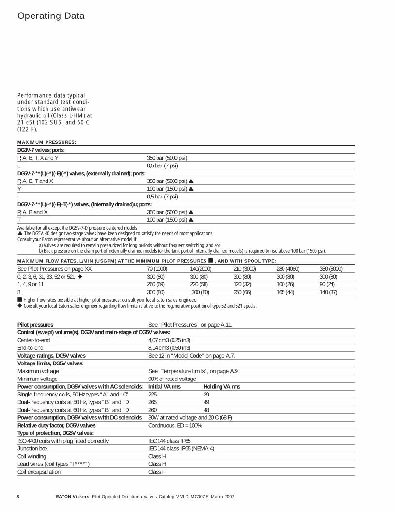
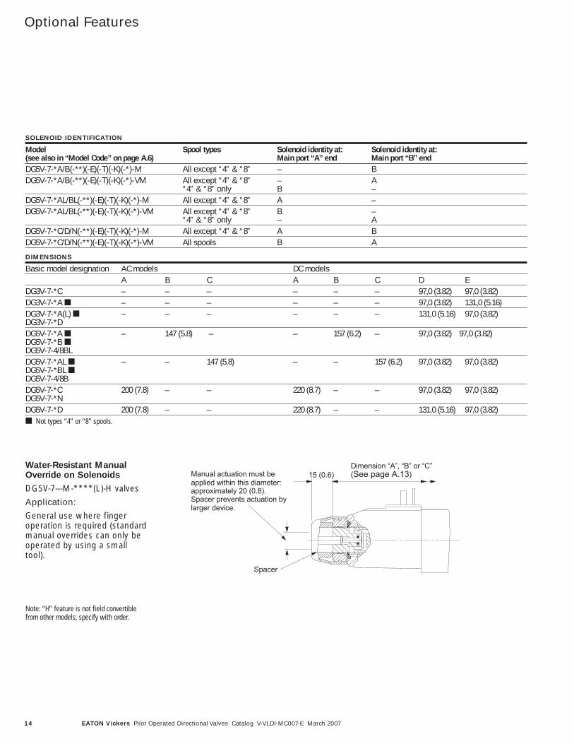
Dimension “A”, “B” or “C”(See page A.13)
Spacer
15 (0.6)Manual actuation must beapplied within this diameter:approximately 20 (0.8).Spacer prevents actuation bylarger device.
Water-Resistant ManualOverride on Solenoids
DG5V-7---M-****(L)-H valves
Application:
General use where finger operation is required (standardmanual overrides can only beoperated by using a smalltool).
Note: “H” feature is not field convertiblefrom other models; specify with order.
SOLENOID IDENTIFICATION
Model Spool types Solenoid identity at: Solenoid identity at:(see also in “Model Code” on page A.6) Main port “A” end Main port “B” endDG5V-7-*A/B(-**)(-E)(-T)(-K)(-*)-M All except “4” & “8” – BDG5V-7-*A/B(-**)(-E)(-T)(-K)(-*)-VM All except “4” & “8” – A
“4” & “8” only B –DG5V-7-*AL/BL(-**)(-E)(-T)(-K)(-*)-M All except “4” & “8” A –DG5V-7-*AL/BL(-**)(-E)(-T)(-K)(-*)-VM All except “4” & “8” B –
“4” & “8” only – ADG5V-7-*C/D/N(-**)(-E)(-T)(-K)(-*)-M All except “4” & “8” A BDG5V-7-*C/D/N(-**)(-E)(-T)(-K)(-*)-VM All spools B A
DIMENSIONS
Basic model designation AC models DC modelsA B C A B C D E
DG3V-7-*C – – – – – – 97,0 (3.82) 97,0 (3.82)DG3V-7-*A ■ – – – – – – 97,0 (3.82) 131,0 (5.16)DG3V-7-*A(L) ■ – – – – – – 131,0 (5.16) 97,0 (3.82)DG3V-7-*DDG5V-7-*A ■ – 147 (5.8) – – 157 (6.2) – 97,0 (3.82) 97,0 (3.82)DG5V-7-*B ■DG5V-7-4/8BLDG5V-7-*AL ■ – – 147 (5.8) – – 157 (6.2) 97,0 (3.82) 97,0 (3.82)DG5V-7-*BL ■DG5V-7-4/8BDG5V-7-*C 200 (7.8) – – 220 (8.7) – – 97,0 (3.82) 97,0 (3.82)DG5V-7-*NDG5V-7-*D 200 (7.8) – – 220 (8.7) – – 131,0 (5.16) 97,0 (3.82)■ Not types “4” or “8” spools.

15EATON Vickers Pilot Operated Directional Valves Catalog V-VLDI-MC007-E March 2007
=
=
=
stab
=
=
=
1
4
2
3
PIN #4Signal
PIN #3Common
PIN #2Not Used
PIN #1+24VDC±20%
Connector Detail
DG5V-7 with Main Stage Spool Monitoring Switch “PPA”, “PPB” or “PPD” Models (Proximity Switch)
Millimeters (inches)
ElectricalInformation
SPECIFICATIONS
Supply Voltage (Vs) 10 to 30 Vdc Supply Current (ls) 8 mA at 24 Vdc (plus load current)Supply Over-voltage Rating: 35 Vdc continuousSupply Reverse Polarity Rating -35 Vdc (with no shorts)Short Circuit Tolerance: Continuous short between any two pinsHigh Potential Test, Pin to Case: 300 VdcElectronmagnetic Compatiblity: ISO 7637 Parts O and I worst case and
Immunity to Radiated Electromagnetic Fields, 10 KHZ to 1 GHZ per SAE J1113/25 Sep 95
Pins to Case Resistance 50 MegohmsLoad Dump Tolerance: 80 Vdc Peak, 400 ms Decay, with 1.5 Ohm
Source ImpedanceSwitching Frequency: 0 to 3K HzOuput: Open collector PNP sourcing, normally openSensing Distance (offset position): 1.27 ± 0.25 mm (.050” ± .010”)Hysteresis: 0.25 mm (.010”) Max.Rise/Fall Time: 6.5/1.5 microsec R1=820 Ohm,
C1=20 pF @ 8VdcOuput Leakage Current 10µa Max.Output Voltage High: +Vs – 2.2 Vdc minimumOutput Load Current: 200 mA Max.Operating Pressure: 350 bar (5000 psi) Operating Temperature: -40˚ to 110˚CHumidity: 0 to 100%
304.2 (11.97)
58.7 (2.31)
102.0 (4.02)
33.0 (1.30)
191.7 (7.55)
M12 ThreadConnection
1
+full spool stroke
1=voltage at pin 4 (Vs – 2.2V) min.0=voltage at pin 4 0.5V min.
0-full spool stroke
0
1
0
PIN 4
PIN 4
center condition (ref.)Functional Diagram - Spring Offset
sensor at "A" port side
sensor at "B" port side
(if applicable)
(if applicable)
.050
.000 from full spool stroke
typical
SENSOR
10K
PIN 3
PIN 4
PIN 1
Common
Signal Output
Power Supply
Electrical information shown in this window is for offset sensing, Proximity Switch "PPA" , "PPB" or "PPD" Models
Output Circuit Wiring Instructions
A Port Side B Port Side

16 EATON Vickers Pilot Operated Directional Valves Catalog V-VLDI-MC007-E March 2007
Signal 1
Signal 0Signal 0
TYPICAL "PCA/PCB" OUTPUT(FOR SENSING CENTER POSITION)
Signal 0 = Voltage at pin 2/4 < 1.8VSignal 1 = Voltage at pin 2/4 > (Vs – 2.5V)
Signal 1
Signal 0Signal 0
TYPICAL "PDA/PDB" OUTPUT(FOR FULL SHIFT SENSING)
CenterSw
itch Point
Switch Point
Full Stroke
Full Stroke
Signal 0 = Voltage at pin 2/4 < 1.8VSignal 1 = Voltage at pin 2/4 > (Vs – 2.5V)
Center
Switch Point
Switch Point
Full Stroke
Full Stroke
Signal 1
Signal 0Signal 0
TYPICAL "PCD" OUTPUT(FOR CENTER SENSING 'A' PORT END, FULL SHIFT SENSING 'B' PORT END)
Signal 0 = Voltage at pin 2/4 < 1.8VSignal 1 = Voltage at pin 2/4 > (Vs – 2.5V)
Center
Switch Point
(Center Sensing)
Switch Point
(Center Sensing)
Full Stroke
Full Stroke
Switch Point
(Full Shift Sensing)
Switch Point
(Full Shift Sensing)
=
=
=
stab
=
=
=
1
4
2
3
OSZILATOR DEMO-DULATOR
OVERLOADPROTECTED
OUTPUT
=
=
=
stabstab
=
= 24V ±20%
LR 1
LR 2
=
Input
Output
Output
Ground
1
4
2
3
Electrical Schematic and Mating Connector Detail
R 1,R 2 = e.g. Coil Resistance of the switch relay >/= 60 OHMSL L
DG5V-7 with Main Stage Spool Monitoring Switch “PCA”, “PCB”, “PDA”, “PDB”, PCD” Models (LVDT style)
Millimeters (inches)
ElectricalInformation
SPECIFICATIONS
Supply Voltage (Vs) 24VDC +/- 20%(Full Wave Bridge with Capacitor)Reverse Polarity Protection Max. 300 V InstalledRipple Voltage 10%Current Consumption 40 mA Approx.Outputs NC Contact PositiveSensing Distance (offset position) 5.85 to 6.15 mmSensing Distance (from center position) ± 0.35 to 0.65 mmHysteresis �0.06mmOutput Voltage (No Short Circuit Protection)
Signal 1 Vs – 2.5 VSignal 0 < 1.8 V
Output Current < 400 mA AT INPUT + 20%Environmental Protection IP65 (With Mounted Plug)Operating Temp Range -20˚ C to +85˚ COperating Pressure 315 bar (4500 psi)CE Declaration of Conformity No. 00 02 002 9 93
ATTENTION: EMC ONLY ENSURED WHEN USING SCREENED CABLES AND SCREENED PLUG CASING!
425,1 (16.73)
220,0 (8.66)
161,0 (6.34)
146,9(5.78)
33,0 (1.30)
M12 ThreadConnection
PIN #4Signal
PIN #3Common
PIN #2Signal
PIN #1+24VDC±20%
Connector Detail
A Port SideB Port Side

17EATON Vickers Pilot Operated Directional Valves Catalog V-VLDI-MC007-E March 2007
Valve for SafetyCircuit Application (35A Spool)
D
A
C
B
Main Stage Hydraulic SymbolA B
P T
MODEL A B C D LEAKAGE P-A FLOW CURVE
mm (in) mm (in) mm (in) mm (in) cc/min (in3/min)DG5V5-35A 118.5 (4.67) 234.7 (9.24) 262.1 (10.32) Available upon request Available upon requestDG5V7-35A 152.1 (5.99) 252.1 (9.92) 286.6 (11.28) Available upon request See belowDG5V8-35A 151.7 (5.97) 346.0 (13.62) 380.5 (14.98) 156 (9.5) Available upon requestDG5V10-35A 230.7 (9.10) 443.4 (17.46) 476.3 (18.8) Available upon request Available upon request
DG5V with PPA Switch Option Shown
DG5V7-35A Flow Curve
500
400
300
200
100
00 10 20 30 40 50 60 70 80
Flow – GPM
p –
PS
I P-A
B-T

18 EATON Vickers Pilot Operated Directional Valves Catalog V-VLDI-MC007-E March 2007
ElectricalInformation
5-pin connectorWhen fitted in single-solenoid valves, e.g.:DG5V-7-*A(L)(-**)-(V)M-FPA5W(L)DG5V-7-*B(L)(-**)-(V)M-FPA5W(L)
5-pin connectorWhen fitted in double-solenoid valves, e.g.:DG5V-7-*C(-**)-(V)M-FPA5W(L)DG5V-7-*D(-**)-(V)M-FPA5W(L)DG5V-7-*N(-**)-(V)M-FPA5W(L)
3-pin connectorWhen fitted in single-solenoid valves, e.g.:DG5V-7-*A(L)(-**)-(V)M-FPA3W(L)DG5V-7-*B(L)(-**)-(V)M-FPA3W(L)
Warning tag:“Electrical power mustbe disconnected beforeremoving or replacingelectrical plug”
7/8 -16 UN-2A thread
16,0 (0.62)
68,75(2.71)
23
451
1-lead(to solenoid “B”)
3-green lead(ground)
5-lead(to solenoid “B”)
2-lead(to solenoid “A”)
4-lead(to solenoid “A”)
1
2 3
3-lead(to solenoid)
1-green lead(ground)
2-lead(to solenoid)
25,4 (1.0) hex.
23
451
1-lead(to solenoid)
3-green lead(ground)
5-lead(to solenoid)
2-lead(capped)
4-lead (capped)
NFPA Connector T3.5.29-1980
DG5V-7-***---FPA3W(L) andDG5V-7-***---FPA5W(L) models
The receptacle is a standardthree or five-pole connectorwith shortened leads and ter-minals added. The five-poleplug has four leads 101,6 mm(4.0 ) long and one of 177,8mm (7.0 ) length. All wireshave US UnderwritersLaboratory-recognized non-solder insulated eyelet termi-nals. The green wire is usedfor the ground (earth) connec-tion (No. 8-size screw fur-nished). Valves are suppliedprewired.
Plugs for ISO 4400 (DIN 43650) Type Coil Connection
For valves with type “U” coils
The cable entry on theseplugs can be repositioned at90 intervals by reassemblyof the contact holder relativeto the plug housing.
The cable entry is Pg.11, forcable Ø 6-10 mm (0.24 to0.39 dia).
Order separately by partnumber.
Connection details and model type/model code references
PLUGS WITHOUT INDICATOR LIGHTS
Part no. Color Use on solenoid coil710775 Black Sol. B710776 Gray Sol. A
PLUGS WITH INDICATOR LIGHTS
Voltage Part no. Gray (sol. A) Part no. Black (sol. B)12-24V 977467 977466100-125V 977469 977468200-240V 977471 977470

19EATON Vickers Pilot Operated Directional Valves Catalog V-VLDI-MC007-E March 2007
*-L****F---)L(**-7-V5GD*-****F---)L(**-7-V5GD
1. For DC coils the +ve lead(s) must be connected to the terminal(s) marked +. When using 3-wire incoming leads to double solenoid valves (i.e. common neutral) the inner pair of terminals must be linked.
2. For correct light indication of energized solenoid ensure that solenoid leads are correctly connected: light terminals are common with each outer pair of solenoid terminals according to the side with + mark.
Terminal strip (part number 890345)clips to cover and can be field-fitted
M3 x 0,5-6H screws (partnumber 186006) 2 each end
Connections to solenoid A(or B, according to model type)
Connections to solenoid B(or A, according to model type)
Rubber gasket
Conduit box cover and nameplatecomplete with sealing gasket and4 screws
Anti-rotation tab ensurescorrect orientation of coverto junction box
28,50(1.12)
30,00(1.18)
Lights
2 lenses in cover
4 terminal screws M3 x 0,5-6H (part number 02-113355)
Terminal Strip and Light OptionsWhen fitted in solenoid controlled valves DG5V-7-**(L)---F****(L).
ElectricalInformation

20 EATON Vickers Pilot Operated Directional Valves Catalog V-VLDI-MC007-E March 2007
Released AssemblyNumbers of Valvewith Main SpoolMonitoring Switch
02-396643 DG5V-7-0A-PPA-T-K-M-U-H7-3002-396644 DG5V-7-0C-PPD-T-K-M-U-A6-305996907-001 DG5V-7-0C-PPD-T-K-M-U-A7-305996914-001 DG5V-7-2A-PCA-T-M-U-H7-305996915-001 DG5V-7-2A-PCD-T-M-U-H7-305996916-001 DG5V-7-2A-PDA-T-M-U-H7-305996917-001 DG5V-7-2A-PPA-T-M-U-H7-305996918-001 DG5V-7-2A-PPD-T-M-U-H7-305996919-001 DG5V-7-2C-PCA-T-M-U-H7-3002-362980 DG5V-7-2C-PCD-T-M-U-H7-3002-362980 DG5V-7-2C-PCD-T-M-U-H7-305996921-001 DG5V-7-2C-PDA-T-M-U-H7-305996922-001 DG5V-7-2C-PPA-T-M-U-H7-30
5996923-001 DG5V-7-2C-PPD-T-M-U-H7-3002-397195 DG5V-7-35A-PPA-E-Z-VM-U-H7-305996924-001 DG5V-7-6C-PCA-T-M-U-H7-305996925-001 DG5V-7-6C-PCD-T-M-U-H7-3002-397714 DG5V-7-6C-PDA-E-M-U-H7-305996926-001 DG5V-7-6C-PDA-T-M-U-H7-305996927-001 DG5V-7-6C-PPA-T-M-U-H7-3002-397713 DG5V-7-6C-PPD-E-M-U-H7-305996928-001 DG5V-7-6C-PPD-T-M-U-H7-30
ASSEMBLY NUMBER MODEL CODE
ASSEMBLY NUMBER MODEL CODE
Size D07/NG16

© 2007 Eaton CorporationAll Rights Reserved Printed in USADocument No. V-VLDI-MC007-ESupercedes GB-2326BMarch 2007
Eaton14615 Lone Oak RoadEden Prairie, MN 55344USATel: 952 937-9800Fax: 952 974-7722www.hydraulics.eaton.com
EatonDr.-Reckeweg-Str. 1D-76532 Baden-BadenGermanyTel: (49) 7221 682-0Fax: (49) 7221 682-788
Eaton20 Rosamond RoadFootscrayVictoria 3011AustraliaTel: (61) 3 9319 8222Fax: (61) 3 9318 5714