PILOT DECODER SYSTEM DESIGN GUIDE - Hunter Industries · 12 T-Splicing Decoder Wire 13 Lightning...
17
PILOT DECODER SYSTEM DESIGN GUIDE hunterindustries.com GOLF IRRIGATION I Built on Innovation ®
Transcript of PILOT DECODER SYSTEM DESIGN GUIDE - Hunter Industries · 12 T-Splicing Decoder Wire 13 Lightning...

PILOT DECODER SYSTEM DESIGN GUIDE
hunterindustries.com
GOLF IRRIGATION I Built on Innovation®

1 2I PILOT DECODER SYSTEM DESIGN GUIDE PILOT DECODER SYSTEM DESIGN GUIDE I
TABLE OF CONTENTS
3 Pilot Decoder System Design Guide
4 Schematic of Decoder System Layout
5 Decoder-In-Head (DIH) Designs
7 Benefits of a Decoder System
8 Electrical Capacity
9 Wire Specifications and Rules
10 Reusing Existing Cable
11 Wire Connectors
12 T-Splicing Decoder Wire
13 Lightning
13 Earth Grounding
16 Decoder-to-Solenoid Wiring
16 Power Factor and Inrush
17 Pilot Decoder System Hardware
18 Pilot Decoder System Components
19 Addressing Decoders
20 Addressing Decoders using the Pilot-DH Decoder Hub
21 Addressing Decoders using the ICD-HP Handheld Programmer
22 Wireless Remote Control
22 Decoder Installation Specifications
23 Layout
24 Wire Use and Conversion Charts
3 4
I PILOT DECODER SYSTEM DESIGN GUIDE PILOT DECODER SYSTEM DESIGN GUIDE I
PILOT DECODER SYSTEM I TABLE OF CONTENTS
PILOT DECODER SYSTEM DESIGN GUIDE
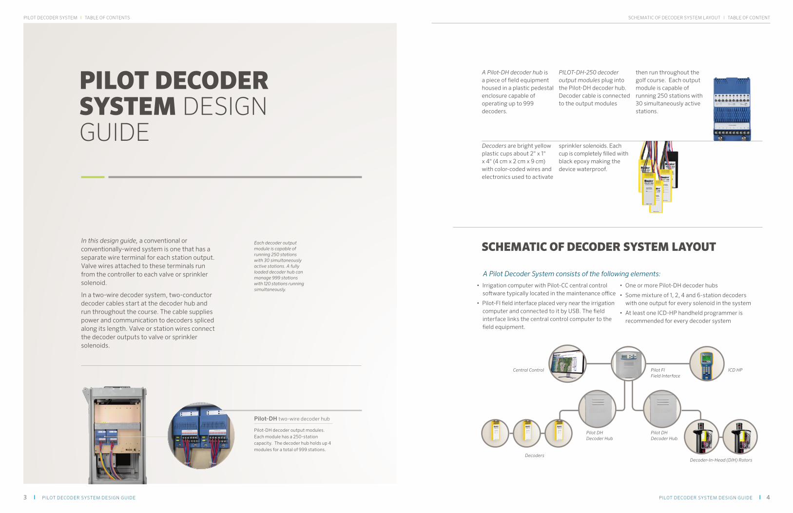
In this design guide, a conventional or conventionally-wired system is one that has a separate wire terminal for each station output. Valve wires attached to these terminals run from the controller to each valve or sprinkler solenoid.
In a two-wire decoder system, two-conductor decoder cables start at the decoder hub and run throughout the course. The cable supplies power and communication to decoders spliced along its length. Valve or station wires connect the decoder outputs to valve or sprinkler solenoids.
Each decoder output module is capable of running 250 stations with 30 simultaneously active stations. A fully loaded decoder hub can manage 999 stations with 120 stations running simultaneously.
Pilot-DH two-wire decoder hub
Pilot-DH decoder output modules. Each module has a 250-station capacity. The decoder hub holds up 4 modules for a total of 999 stations.
SCHEMATIC OF DECODER SYSTEM LAYOUT
A Pilot Decoder System consists of the following elements:
• Irrigation computer with Pilot-CC central control software typically located in the maintenance office
• Pilot-FI field interface placed very near the irrigation computer and connected to it by USB. The field interface links the central control computer to the field equipment.
• One or more Pilot-DH decoder hubs
• Some mixture of 1, 2, 4 and 6-station decoders with one output for every solenoid in the system
• At least one ICD-HP handheld programmer is recommended for every decoder system
A Pilot-DH decoder hub is a piece of field equipment housed in a plastic pedestal enclosure capable of operating up to 999 decoders.
PILOT-DH-250 decoder output modules plug into the Pilot-DH decoder hub. Decoder cable is connected to the output modules
then run throughout the golf course. Each output module is capable of running 250 stations with 30 simultaneously active stations.
Decoders are bright yellow plastic cups about 2" x 1" x 4" (4 cm x 2 cm x 9 cm) with color-coded wires and electronics used to activate
sprinkler solenoids. Each cup is completely filled with black epoxy making the device waterproof.
Central Control
DecodersDecoder-In-Head (DIH) Rotors
Pilot DHDecoder Hub
Pilot DHDecoder Hub
Pilot FIField Interface
ICD HP
SCHEMATIC OF DECODER SYSTEM LAYOUT I TABLE OF CONTENT

5 6I PILOT DECODER SYSTEM DESIGN GUIDE PILOT DECODER SYSTEM DESIGN GUIDE I
DECODER OPERATION I TABLE OF CONTENTDECODER SYSTEM I TABLE OF CONTENTS
Decoder-In-Head designs make the most efficient use of hardware possible in golf designs. Combining the benefits of the Hunter Totally Top Serviceable (TTS) golf rotors with the power and flexibility of decoder technology, DIH systems house the decoder within the rotor compartment. This configuration eliminates valve boxes on the fairways and wire splices between the decoder and the rotor. Hunter DIH rotors are available in single or two-station decoder configurations, pre-wired to the rotor solenoid and ready to install.
Hunter DIH Rotors may also be programmed and inspected through the TTS flange compartment lid, wirelessly, with the ICD-HP handheld programmer, without removing a single screw.
DECODER-IN-HEAD (DIH) DESIGNS
DIH Rotor
Decoder-In-Head rotor with single-station decoder pre-installed
Decoder-In-Head: This configuration eliminates valve boxes on the fairways and all wire splices between the decoder and the rotor.
Each DIH rotor is its own valve box for the decoder.
Surge arrestors (PILOT-SG) are placed along the main two-wire path, near the tee-splices that connect individual laterals. The surge arrestors are located in small valve boxes, and connected to earth ground hardware located well away from the two-wire path itself (see “Earth Ground Placement”, p. 13). This eliminates the need for any additional components or boxes on the playing surface.
Shorter lateral runs (6-8 decoders or less): Place PILOT-SG Surge Arrestors in the main two-wire path, on the hub side of the tee splice. In low lightning areas, use one surge arrestor
for every two rows. In higher lightning areas, place one arrestor per lateral.
Longer lateral runs (10 decoders or more): Place the PILOT-SG Surge Arrestors on the lateral side of the tee splice, isolating the lateral run from the main two-wire path.
The spacing of the surge arrestors may be adjusted depending on how much lightning is experienced in the area. The number and placement of surge arrestors is calculated to minimize exposure to surge between any two grounded points.
DECODER-IN-HEAD SURGE PLACEMENTS Valve Box for wiring and decoders Pilot-SG placement for short runs Pilot-SG placement for long runs (6-8 rotors) Surge Ground
DECODER-IN-HEAD ROTOR
VALVE BOX
①
②
③④
⑤
⑥
⑦
⑧
⑨
① FINISH GRADE
② G885D FULL/PART CIRCLE ROTOR UNITIZED PVC AS SPECIFIED
③ 1 ½" OR AS SPECIFIED
④ SUB MAIN PIPE
⑤ SUB MAIN LINE
⑥ 1 ½" MALE ACME
⑦ WIRE SPLICE 3M DBRY-6 ON TWO-WIRE PATH
⑧ TWO WIRE PATH
⑨ DECODER/SOLENOID ASSEMBLY INSIDE TTS COMPARTMENT

7 8I PILOT DECODER SYSTEM DESIGN GUIDE PILOT DECODER SYSTEM DESIGN GUIDE I
ELECTRICAL CAPACITY I TABLE OF CONTENTDECODER SYSTEM BENEFITS I TABLE OF CONTENTS
System Flexibility
As long as the two-wire path is reasonably accessible throughout the golf course, stations can be added later by simply splicing a new two-wire path leg onto the existing cable, then splicing additional decoders into the path wherever they are needed.
Decoder wire runs are typically T-spliced to follow pipe trenches and minimize wasted wire.
Because 999-station Pilot decoder hubs are housed in weatherproof plastic pedestals, they can be placed strategically to reduce the amount of decoder cable when compared to systems which require all decoder cable be routed back to the maintenance office.
Also, the 999-station pedestal-mounted hub architecture of Pilot decoder systems is the
perfect compromise between central computer-only systems and multiple field controllers. For most golf courses around the world, one hub is sufficient. In drier climates, a golf course may need multiple hubs. You can have as few as one and as many as 999 decoder hubs on your golf course depending on your need for infield control.
Cost Savings
One of the most important benefits of a decoder system is that it saves wire. With a Pilot decoder system, up to 250 stations can be managed by each output module over a single two-conductor cable. One decoder hub can manage up to 999 stations over 4 two-conductor decoder cables. To manage 999 stations using a conventionally wired system would require 999 valve wires plus several valve common wires.
BENEFITS OF A DECODER SYSTEM
ELECTRICAL CAPACITY
Pilot decoder hubs can run 30 solenoids at a time on each 250-station output module. That means a fully loaded 999-station decoder hub can run up 120 solenoids at one time.
With 14 AWG (2.1 mm²) Hunter ID1 wire, a Pilot decoder hub can activate solenoids up to 8,000 feet (2½ km) away. With 12 AWG (3.3 mm²) Hunter ID2 wire, they can operate stations up to 14,000 feet (4¼ km) away.
Pilot decoder systems have sufficient terminals to connect six wire paths to each 250-station output module. Therefore, a controller using ID1 cable can have up to six 8,000 foot (2½ km) legs for each of four Pilot-DH-250 output modules. If preferred, all 250 stations can be connected to a single two-wire cable.
Note: AC power supply wires for the Pilot-DH decoder hub must be 14 AWG (1.5 mm²) or larger.
Pilot-DH decoder hubs include full-featured face packs for convenient, in-field control anytime and standalone watering during the construction phase of a project. Hunter’s unique Straight Talk™ technology means that by adding a PILOT-MOD-UHF radio communications module, the TRNR maintenance radio can be used for remote control before the central control is even set up.
CABLE NEEDED FOR A CONVENTIONAL FIELD CONTROLLER CABLE NEEDED FOR A TWO-WIRE DECODER SYSTEM
VIBRATORY PLOWS CUT SLOTS IN THE SOIL RATHER THAN DIGGING A TRENCH RESULTING IN VERY LITTLE DAMAGE TO THE TURF
The Pilot-DH decoder hub electrical specifications:
PILOT-DH DECODER HUB POWER SUPPLY
Input voltage 120/230 VAC at 50/60 Hz
Input current for 120 VAC 5.5 amps maximum (fully loaded and running maximum simultaneous stations)
Input current for 230 VAC2.75 amps maximum (fully loaded and running maximum simultaneous stations)

9 10I PILOT DECODER SYSTEM DESIGN GUIDE PILOT DECODER SYSTEM DESIGN GUIDE I
WIRE SPECIFICATIONS I TABLE OF CONTENTWIRE SPECIFICATIONS I TABLE OF CONTENTS
Hunter requires twisted wire meeting the above specification on all paths. The twist in the wire is an essential part of the surge suppression scheme. Because lightning damage is never covered by warranty, it is in the installer’s best interest to share what Hunter has learned in nearly two decades of decoder installations by using twisted wire that meets all the above specifications.
The twisted pairs are not shielded or armored. Voltage on the two-wire path is under 40 VAC so unless local regulations require it, conduit is not necessary. Shielding, steel armor and conduit will not inhibit performance and can be used if desired.
Each two-wire run from a 250-station output module is called a path.
A fully loaded hub therefore can have a minimum of four (one for each of four modules) to 24 (six for each of four modules) paths. For each output module, up to 250 decoders can be installed in any combination of one to six cable paths.
Cable paths should never be connected from one output module to another. For example, a cable extending from output module 1 should not be connected to output module 2, 3 or 4.
Each path runs from its output module to the last decoder in the path and simply stops there.
WIRE SPECIFICATIONS AND RULES
Decoder cable and how it is installed, is a key factor in successful decoder installations. Substitution of wire and wire splices is the major cause of start-up service problems and is done at the installer’s own risk.
Hunter cable types for use with Pilot decoder systems:
MODEL AWG/METRIC CONDUCTOR SPOOL SIZE COLOR OPTIONS
ID1 14 AWG (2.1 mm²) Two insulated (one red and one blue) soft-drawn solid copper wires, twisted with a minimum lay of 4 inches (10 cm) enclosed in a direct-burial, high density polyethylene jacket
2,500 feet (760 m) Grey, Purple, Yellow, Orange, Blue, Tan
ID2 12 AWG (3.3 mm²) Two insulated (one red and one blue) soft-drawn solid copper wires, twisted with a minimum lay of 4 inches (10 cm) enclosed in a direct-burial, high density polyethylene jacket
2,500 feet (760 m) Grey, Purple, Yellow, Orange, Blue, Tan
PILOT-DH DECODER HUB OUTPUT VOLTAGE
Pilot-DH-250 decoder output module voltage
40V
Maximum allowable voltage drop on two-wire path 20V
PILOT DECODERS
Standby current (solenoid off) 1.2 mA
Active current (solenoid on)45 mA for Hunter solenoid with Power Factor set to two (default)
HUNTER ID DECODER CABLE
REUSING EXISTING CABLE
Using wire left in the ground from a previous system is never a good idea and may void your warranty. Buried cable ages over time. As the cable ages, wire insulation shrinks, resulting in ground faults. Even if the cable in the ground has not aged to the point where it is having problems, the life of that cable is already reduced.
Often, older systems are replaced because they do not work. Quite often a big part of the problem with these systems is the poor condition of the cable caused by multiple repairs and aging. From a more practical standpoint, the existing cable is unlikely to meet the specifications for gauge, twist and solid copper. Often
the conductor insulation is not color-coded red/blue which can lead to confusion during the installation process. In short, experience has shown that trying to re-use existing wire usually takes longer to repair for use with the new system and tends to cost more in the long run.

11 12I PILOT DECODER SYSTEM DESIGN GUIDE PILOT DECODER SYSTEM DESIGN GUIDE I
WIRING CONNECTIONS I TABLE OF CONTENTWIRING CONNECTIONS I TABLE OF CONTENTS
Whenever a splice is made, it is important to leave adequate slack in the wires. Leave 5 feet (1½ m) of slack to allow for convenient service or inspection and to prevent contraction of
the wire from damaging the connections. Wire slack may be coiled neatly or otherwise tucked out of the way.
WIRE CONNECTORS
All wire joints in the red/blue two-wire path must be made with 3M Company DBRY-6 or equal waterproof connectors. DBRY-6 connectors are rated for 600V and should not be confused with DBR/DBY connectors which are rated for 30V.
Decoder-to-solenoid connections may be made with standard DBY waterproof connectors. These connectors are rated for 30 V. As with the red/blue two-wire path, leave 5 feet (1.5 m) of slack to allow for convenient service or inspection and to prevent contraction of the wire from damaging the connections.
T-SPLICING DECODER WIRE
Cable paths in the Pilot decoder system can be T-spliced. T-splices consist of making a three-way connection in the red wire and a three-way connection in the blue wire. All T-splices must be made in valve boxes with high quality waterproof splices such as 3M DBRY-6 which are large enough to hold three 14 AWG (2.1 mm²) conductors (for ID1 wire) or three 12 AWG (3.3 mm²) conductors (for ID2 wire.)
It is especially important to allow adequate slack in a three-way splice. Each splice should be able to be withdrawn from the valve box for above-ground inspection and service.
Where possible, run the decoder cable in the same trench as the irrigation pipe. The pipe will provide some protection to the wire and logically leads to the valves where decoders will be positioned.
If ID1 wire is used and the total distance from the decoder hub to the end of each arm of the T-splice is less than 8,000 feet (2½ km), the system meets specification. This is true even if the total amount of wire is more than 8,000 feet (2½ km).
3M™ DBR/Y-6 DIRECT-BURY SPLICE INSTALLING A DIRECT-BURY SPLICE
Valve Box Wiring
Typical wiring connections in a valve box
For example if 14 AWG (2.1 mm²) ID1 wire is used and a T-splice is placed 4,000 feet (1¼ km) from the controller, and two arms in different directions each run an additional 4,000 feet (1¼ km), the wire is within specifications. It is only 8,000 feet (2½ km) to the end of each arm of the T from the controller even though there is 12,000 feet (3½ km) total wire connected to the output.
It is possible to have more than one splice in a wire run, provided all the above conditions are met.
In very large systems, the length of the wire run and the number of decoders installed along its length may reduce the number of stations which can be run simultaneously near the end of the wire path. This will not damage the equipment but may require adjusting station timing to prevent under-powering the solenoid outputs.
Pilot DHDecoder Hub
3-Way Splice
4,000 ft (1¼ km) ID1 cable
8,000 ft (2½ km) ID1 cable
4,000 ft (1¼ km) ID1 cable
4,0
00
ft (
1½ k
m) I
D1 c
able

13 14I PILOT DECODER SYSTEM DESIGN GUIDE PILOT DECODER SYSTEM DESIGN GUIDE I
GROUNDING DESIGN I TABLE OF CONTENTEARTH GROUNDING I TABLE OF CONTENTS
A large copper ground lug or clamp is provided for connection of bare copper wire to earth grounding hardware. To ensure the ground grid dissipates excess energy into the earth and not onto the decoder system’s two-wire path where it could damage other system components, the grounding wire should be laid perpendicular to the two-wire path.
EARTH GROUNDING
Earth grounding of decoder systems requires planning and careful installation. Properly grounded decoder systems perform very well in high-lightning regions. Poor grounding will result in unnecessary equipment losses and irrigation downtime.
Earth grounding for Pilot decoder systems should follow specifications published by the American Society of Irrigation Consultants (ASIC) and published as a design guide called Earth Grounding Electronic Equipment in Irrigation Systems. The design guide can be found online at: http://www.asic.org/Design_Guides.aspx
Pilot decoder systems required ground grids:
LOCATIONS CONNECTIONS RESISTANCE TO GROUND PLACEMENT
Central Control Copper ground lug inside Pilot-FI field interface
< 10 Ω (using megger) 1 at central control
Decoder Hubs Copper ground lug inside Pilot-DH plastic pedestal
< 10 Ω (using megger) 1 at each hub
Pilot-FI and Pilot-DH grounding grid design
Typical ASIC grounding grid design for Pilot-DH hubs and Pilot-FI field interface
LIGHTNING
While no irrigation system is immune to lightning, decoder systems have less wire in the ground and when properly installed, have excellent grounding and surge suppression. They are popular in regions with high lightning exposure.
PHOTO COURTESY OF NASA MSFC LIGHTNING IMAGING SENSOR (LIS) SCIENCE TEAM

15 16I PILOT DECODER SYSTEM DESIGN GUIDE PILOT DECODER SYSTEM DESIGN GUIDE I
DECODER-TO-SOLENOID WIRING I TABLE OF CONTENTGROUNDING REQUIREMENTS I TABLE OF CONTENTS
POWER FACTOR AND INRUSH
The color-coded station outputs of individual decoders are designed to operate standard Hunter golf irrigation solenoids. Solenoid inrush current is the initial increase in power required to energize the solenoid and overcome water pressure to open the diaphragm valve. Solenoid holding current is the power required by the solenoid to keep the valve open once it has been opened by the inrush current.
Note: Factory preset power factor and inrush settings should only be changed in consultation with Hunter technical personnel.
For Pilot decoders the Power Factor is factory preset to 2. The inrush setting for Pilot decoders is 5. This is the correct setting for most applications. Some high-draw solenoids and pump start relays may require higher inrush settings.
Pilot decoders that feature integrated surge suppression are equipped with a bare copper wire for connection to earth ground hardware. Pilot DIH systems required external surge suppression, by adding Pilot-SG suppressors at specified intervals. These are also equipped with a bare copper wire for connection to earth ground hardware.
The bare copper wire for the integrated ground should be connected at every 12th decoder or every 1,000 feet (300 m) of wire run, whichever is shorter. The decoder station size (1, 2, 4 or 6) is not taken into account. Six-station decoders, just like single-station decoders, count as 1 of the 12 decoders.
The final decoder in any wire run should be grounded. This includes the final decoders in each of the different arms of a T-spliced junction.
Ground wires on decoders between the ones that have been connected are not used. It is not necessary to remove the unused ground wire or bury it; simply fold it out of the way. This allows future additional grounding or use of the decoder in another location.
Earth Ground Placement:
LOCATIONS CONNECTION RESISTANCE TO GROUND PLACEMENT
Decoder integrated surge connection
Bare copper wire from integrated surge suppressor on each decoder
< 10 Ω (using megger) Every 12th decoder or 1,000 feet (300 m) whichever is shorter and at the end of each wire run
Surge arrestors when using DIH rotors
Requires addition of Pilot-SG surge arrestors
< 10 Ω (using megger) Every 12th decoder or 1,000 feet (300 m) whichever is shorter and at the end of each wire run
Place Ground Plate in 6” wide trench, perpen-dicular to the yellow Shielding Wire, 8 feet away, 36” below ground level.
Solid bare copper
Shielding Wire
Ground level
Decoder Grounding
Note: Decoder grounding hardware should always be placed at right angles to the run of the two-wire path.
Pilot-Decoder grounding plate installation
Typical grounding plate installation for Pilot decoder integrated surge protection. Installation using Pilot-SG inline surge protectors is similar.
DECODER-TO-SOLENOID WIRING
From the decoder outputs to the individual solenoids, use standard irrigation wire sized for the length of the run. Wiring from the decoder to the solenoid should not exceed 240 feet (73 m). If decoder-to-solenoid distance is over 20 feet (7 m) you can twist the wire to aid in surge suppression. This is especially important in high-lightning areas.
For installations using electric inline valves, the decoder is often in the same valve box as the solenoid it controls. In these cases, standard 18 AWG (1.0 mm²) wire can be used.
Each station output on a decoder can power up to two standard Hunter golf solenoids. When doubling solenoids on a decoder output, the solenoids must be wired in parallel rather than in series. The decoder station output leads should run to the two leads from the first solenoid then
connect (usually in a three-way splice) to the leads from the second solenoid.
TIME
AM
PS
Inrush current
Holding current
INRUSH CURRENT ENERGIZES THE SOLENOID TO OPEN THE VALVE, THEN POWER IS REDUCED AND THE VALVE IS KEPT OPEN BY THE HOLDING CURRENT
POWER FACTOR AND INRUSH SETTING IN PILOT-DH DECODER HUB
Pilot Decoder
Station wires
Rotorsolenoidwire
Rotorsolenoidwire
Decoder communicationcable
Pilot Decoder
Station wires
Rotorsolenoidwire
Rotorsolenoidwire
Decoder communicationcable
Pilot Decoder
Station wires
Rotorsolenoidwire
Rotorsolenoidwire
Decoder communicationcable
Pilot Decoder
Station wires
Rotorsolenoidwire
Rotorsolenoidwire
Decoder communicationcable
WRONG: PARALLEL WIRING
CORRECT: SERIES WIRING

17 18I PILOT DECODER SYSTEM DESIGN GUIDE PILOT DECODER SYSTEM DESIGN GUIDE I
PILOT DECODER SYSTEM HARDWARE I TABLE OF CONTENTPILOT DECODER SYSTEM HARDWARE I TABLE OF CONTENTS
When using solenoids other than Hunter, the manufacturer’s solenoid specifications should be consulted before planning a system.
In a Pilot decoder system you never need to open splices, cut wire or otherwise disrupt the system to make changes to the Power Factor or inrush settings.
If it becomes necessary to customize these settings for use with non-standard solenoids, both the ICD-HP handheld programmer and Pilot-DH decoder hub can be used to make the adjustments. The ICD-HP connects to a decoder wirelessly by placing its sensor close to the decoder. The Pilot-DH decoder hub has a programming port in the face pack.
Pilot-DH decoder hub
Decoder programming port on Pilot-DH decoder hub
Note: Each color-coded station output on a decoder generates the energy required to operate up to 24 VAC solenoids. This energy is not running at 50/60 Hz and will therefore not look like 24 VAC on a conventional volt meter.
PILOT DECODER SYSTEM HARDWARE
Pilot decoder hubs are designed to work with either 120 VAC or 230 VAC input power. The hub uses an advanced power supply which automatically detects and adjusts for the type of incoming power, therefore there is no switch for changing between 120 VAC and 230 VAC.
PILOT DECODER SYSTEM COMPONENTS
Pilot decoders are bright yellow to distinguish them from other decoder models. The color also makes them easier to find on construction sites and in the bottom of dark valve boxes. Decoders are completely waterproof. Pilot decoders have built-in surge suppression with a bare copper wire for connection to a ground rod or plate. DIH rotors do not include integrated surge protection therefore separate PILOT-SG inline surge protection devices are required.
Each Pilot decoder has one pair of communication wires for connecting to the two-wire path. One of the wires is red. The other is blue. Inside the Hunter ID wire cable there are two conductors; one red and one blue to make wiring the system easy with little risk of mistakes.
In addition to the red/blue communication wires, Pilot decoders include pairs of color-coded wires.
These are station output wires. The colors are used to identify the decoder’s station outputs. Pilot-100 single-station decoder have a single pair of black station wires. On two-station decoders the first output is black and the second output is yellow. A different color is used for each output.
Each station can be turned on independently of the others and each station output can activate up to two solenoids.
Theoretically, each multi-station decoder can activate the number of stations x 2 solenoids simultaneously. For example, a six-station decoder can operate up to (6 stations) x (2 solenoids) = 12 total solenoids. Some limitations may apply for very high-draw solenoids, and pump start relays.
Pilot decoders are CE approved and meet other relevant international standards as well.
Note: The decoders themselves are low-voltage products and do not require a separate UL listing on their own. They are part of a UL-listed decoder system.
MODEL STATION COUNT
STATION WIRE COLORS
PILOT-100 1 1- Black
2- Yellow
3- Green
4- White
5- Orange
6- Purple
PILOT-200 2
PILOT-400 4
PILOT-600 6
PILOT-SG NA
Pilot Decoders
Pilot decoders are yellow to easily distinguish them from other decoders

19 20I PILOT DECODER SYSTEM DESIGN GUIDE PILOT DECODER SYSTEM DESIGN GUIDE I
ADDRESSING DECODERS I TABLE OF CONTENTADDRESSING DECODERS I TABLE OF CONTENTS
ADDRESSING DECODERS USING THE PILOT-DH DECODER HUB
The Pilot-DH decoder hub can be used to address any Pilot decoder. Every decoder, regardless of the station count, will have one red and one blue wire. These are the communication wires which will later be spliced onto the decoder cable. The red and blue wires from the decoder are inserted
into the programming port on the face pack of the Pilot decoder hub. It does not matter which color (red/blue) goes in which hole of the programming port. While addressing the decoder it can be placed in the recessed holder on the right side of the pedestal.
With Pilot decoders, the address can be specified in advance so the number can be put into a record drawing. Once the decoders are spliced onto the wire path, the installer can take a copy of the plan and the ICD-HP wireless handheld programmer, then walk along the wire path programming each decoder.
Later, if a decoder must be replaced, its number can be determined from the label where
it was written or from the record drawing. The replacement decoder is given the same address and everything is ready to go. It can be immediately tested. With preaddressed decoders, the replacement decoder arrives with an unknown address. When it is installed, the new random address must be noted before the decoder can be tested.
ADDRESSING DECODERS
Each Pilot decoder arrives without a station address. Decoder addresses must be assigned before they can be used. Each output on a decoder needs its own, unique address. That means a Pilot-100 single-station decoder needs 1 address and a Pilot-600 six-station decoder needs 6 addresses. Pilot decoder addresses can be any number from 1 to 999. Address numbers can be used only once. Pilot-DH decoder hubs accept up to four 250-station output modules. Although any numbers from 1 to 999 may be used as decoder addresses, numbering per output module must be as shown here.
Stations 1-250 Stations 251-500 Stations 501-750 Stations 751-999
PILOT-DH-250 Output Modules
Decoder addressing for output modules in a Pilot-DH decoder hub Pilot-DH decoder hub
Programming port in Pilot-DH face pack with decoder wires inserted
After inserting the wires in the programming port, press the SETTINGS button on the decoder hub face pack. Choose TESTING from the menu shown on the display then select PROGRAM A DECODER. The decoder hub will search for a decoder connected to the programming port. If a
decoder is found, the display will change to show all available stations on the decoder. Station outputs will be identified by number and also by the wire color for each output on the decoder. Using the keypad and arrow buttons on the face pack, assign each station an address.
PILOT-DH DECODER HUB PROGRAMMING SCREEN FOR A SIX-STATION DECODER
Note: Do not create duplicate stations. Every decoder output on the golf course needs a unique ID. The Pilot decoder hub and decoders have two-way communication between each other on the two-wire path. Each command from the hub requires reply from the decoder. If two decoders have the same address, they will both try to respond in which case both may turn on, neither may turn on, or there will be communication errors.
Once all station outputs have been addressed, press the SAVE button. As the decoder hub configures the decoder with the desired addresses, the programming light on top of the face pack will blink.
4

21 22I PILOT DECODER SYSTEM DESIGN GUIDE PILOT DECODER SYSTEM DESIGN GUIDE I
DECODER INSTALLATION SPECS I TABLE OF CONTENTADDRESSING DECODERS I TABLE OF CONTENTS
The Hunter ICD-HP is a powerful handheld device that should be included with any Pilot decoder system. It can be used to wirelessly link to a decoder even if it is inside the TTS compartment of a DIH rotor. It is used to troubleshoot decoder systems, update decoder addresses, inrush and Power Factor settings, perform functional tests on the decoders, and update decoder firmware.
To set a decoder’s address using the ICD-HP, turn the unit on. Connect to a decoder and select the DECODER PROGRAMMING MENU. Next select PROGRAM DECODER, press NEXT and the display will show all available station outputs. Use the arrow keys to select the desired output, then use the number keys to set the address for the selected output.
Note: Do not create duplicate stations. Every decoder output on the golf course needs a unique ID. The Pilot decoder hub and decoders have two-way communication between each other on the two-wire path. Each command from the hub requires reply from the decoder. If two decoders have the same address, they will both
try to respond in which case both may turn on, neither may turn on, or there will be communication errors.
ADDRESSING DECODERS USING THE ICD-HP HANDHELD PROGRAMMER
Note: To use the ICD-HP wire-lessly, the decoder must be connected to the wire path and be powered on. The ICD-HP can be used with decoders that are not powered.
ICD-HP PROGRAMMING SCREEN FOR A SIX-STATION DECODER
PILOT-MOD-UHF RADIO MODULE
ICD-HP FOR PILOT DECODERS
ICD-HP BEING USED TO WIRELESSLY PROGRAM A HUNTER DIH GOLF ROTOR
Cable
It is important to always use solid core, color-coded, twisted-pair cable. The twist of the cores protects the system from most types of noise and small surges. This is the same technology that has been used by telephone and data companies for many years. The size of cable can be selected depending on run distance and the number of standby and active decoders on the path.
As a general rule, 14 AWG (2.1 mm²) ID1 wire is recommended for wire path lengths up to 8,000 feet (2½ km) and 12 AWG (3.3 mm²) ID2 wire for wire path lengths up to 14,000 feet (4¼ km).
These maximum wire path lengths are for activating 30 standard Hunter golf solenoids
with 250 single station decoders per output module. If the output module must activate more than 30 solenoids at a time, the maximum wire length must be shortened. If the maximum wire length needs to be longer, fewer stations should be run simultaneously. See the charts at the end of this manual for guidelines regarding wire lengths and simultaneous stations.
Note: It is not the total system cable length; it is the length from the decoder output to the farthest decoder on each path.
Avoid running power cables and decoder cable in parallel, especially if they are close. If a high voltage cable must be crossed, it is best to cross at right angles.
DECODER INSTALLATION SPECIFICATIONS
General
Cable layout and design is relatively simple. The general rule is to run the two-wire paths in the pipe trenches so that they pass near each solenoid
location. In special circumstances, or if cable sizes need to be trimmed down to a minimum, the charts in this document can be used.
WIRELESS REMOTE CONTROL
The TRNR maintenance radio is a narrow band UHF radio operating in the 450-470 MHz frequency range. The maintenance radio can wirelessly control Pilot decoder hubs with or without a central control in place. This option requires installation of a PILOT- MOD-UHF radio module. The operator may then use a Hunter model TRNR portable radio or a similarly programmed UHF radio with DTMF keypad to control of up to 999 stations.
TRNR REMOTE CONTROL RADIO

23 24I PILOT DECODER SYSTEM DESIGN GUIDE PILOT DECODER SYSTEM DESIGN GUIDE I
WIRE USE CHARTS I TABLE OF CONTENTDECODER INSTALLATION SPECS I TABLE OF CONTENTS
LAYOUT
The maximum number of decoders on one decoder output module is 250 stations. Each decoder can have a maximum of two standard Hunter golf solenoids.
A cable path can be branched off as many times as necessary. If the branches are long, consider using a decoder cable switch device (Paige# 270DCFD3 or equal) to isolate the branches for troubleshooting purposes.
Decoder cable switch
Decoder cable switch device made by Paige Electronics
4,000
6,000
8,000
10,000
12,000
14,000
16,000
18,000
20,000
50 70 90 110 130 150 170 190 210 230 250
Wire
Pat
h Le
ngth
(fee
t)
Total Number of Decoders on Wire Path
Active Stations Based on Wire Length and Number of DecodersUsing ID2 (12 AWG) Wire
15 Active Stations
20 Active Stations
25 Active Stations
30 Active Stations
WIRE USE CHARTS

25 26I PILOT DECODER SYSTEM DESIGN GUIDE PILOT DECODER SYSTEM DESIGN GUIDE I
WIRE USE CHARTS I TABLE OF CONTENTS WIRE USE CHARTS I TABLE OF CONTENT
2,000
2,500
3,000
3,500
4,000
4,500
5,000
5,500
6,000
50 70 90 110 130 150 170 190 210 230 250
Wire
Pat
h Le
ngth
(met
ers)
Total Number of Decoders on Wire Path
Active Stations Based on Wire Length and Number of Decoders²) Wire
15 Active Stations
20 Active Stations
25 Active Stations
30 Active Stations
1,000
1,500
2,000
2,500
3,000
3,500
50 70 90 110 130 150 170 190 210 230 250
Wire
Pat
h Le
ngth
(met
ers)
Total Number of Decoders on Wire Path
Active Stations Based on Wire Length and Number of DecodersUsing ID1 (2.1 mm²) Wire
15 Active Stations
20 Active Stations
25 Active Stations
30 Active Stations

27 28I PILOT DECODER SYSTEM DESIGN GUIDE PILOT DECODER SYSTEM DESIGN GUIDE I
WIRE USE CHARTS I TABLE OF CONTENTS WIRE GAUGE CONVERSION CHARTS I TABLE OF CONTENT
AWG SIZE METRIC (MM2) CIRCULAR MILS EQUIVALENT CIRCULAR MILS
APPROXIMATE WIRE DIAMETER
INCHES MM
– 0.50 – 937 0.032 0.81
20 – 1,020 – 0.036 0.91
– 0.75 – 1,480 0.039 0.99
18 – 1,620 – 0.046 1.16
– 1.00 – 1,974 0.051 1.30
16 – 2,580 – 0.051 1.29
– 1.50 – 2,960 0.063 1.60
14 – 4,110 – 0.073 1.84
– 2.50 – 4,934 0.081 2.06
12 – 6,530 – 0.092 2.32
– 4.00 – 7,894 0.102 2.59
10 – 10,380 – 0.116 2.93
– 6.00 – 11,840 0.126 3.21
8 – 16,510 – 0.146 3.70
– 10.00 – 19,740 0.162 4.12
6 – 26,240 – 0.184 4.66
– 16.00 – 31,580 0.204 5.18
4 – 41,740 – 0.232 5.88
– 25.00 – 49,340 0.260 6.60
2 – 66,360 – 0.292 7.42
– 35.00 – 69,070 0.305 7.75
1 – 83,690 – 0.332 9.43
– 50.00 – 98,680 0.365 9.27
Conversion chart for American Wire Gauge (AWG) to metric system
4,000
5,000
6,000
7,000
8,000
9,000
10,000
11,000
12,000
50 70 90 110 130 150 170 190 210 230 250
Wire
Pat
h Le
ngth
(fee
t)
Total Number of Decoders on Wire Path
Active Stations Based on Wire Length and Number of DecodersUsing ID1 (14 AWG) Wire
15 Active Stations
20 Active Stations
25 Active Stations
30 Active Stations

30PILOT DECODER SYSTEM DESIGN GUIDE I 29 I PILOT DECODER SYSTEM DESIGN GUIDE
WIRE GAUGE CONVERSION CHART I TABLE OF CONTENTS
AWG SIZE METRIC (MM2) CIRCULAR MILS EQUIVALENT CIRCULAR MILS
APPROXIMATE WIRE DIAMETER
INCHES MM
1/0 – 106 – 0.373 9.46
2/0 – 133 – 0.419 10.60
– 70 – 138.1 0.430 10.90
3/0 – 168 – 0.471 12.00
– 95 – 187.5 0.504 12.80
4/0 – 212 – 0.528 13.40
– 120 – 237.8 0.567 14.40
– – 250 – 0.575 14.60
– 150 300 – 0.630 16.00
– – 6,530 – 0.092 2.32
– 185 – 365.1 0.700 17.80
– – 400 – 0.728 18.50
– 240 – 473.6 0.801 20.30
– – 500 – 0.814 20.70
– 300 – 592.1 0.700 17.80
– – 600 – .0893 22.10
– – 700 – 0.964 24.50
– – 750 – 0.999 25.40
– 400 – 789.4 1.026 26.10
– – 800 – 1.032 26.20
– 500 – 986.8 1.152 29.30
– – 1,000 – 1.153 29.30
– 625 – 1,233.7 1.287 32.70
Conversion chart for American wire gauge to metric system

Helping our customers succeed is what drives us. While our passion
for innovation and engineering is built into everything we do, it is our
commitment to exceptional support that we hope will keep you in
the Hunter family of customers for years to come.
© 2014 Hunter Industries Incorporated Please recycle. GLIT-087 4/14
This brochure was printed on Forest Stewardship Council® (FSC) certified paper with soy inks. The FSC is an international organization established to promote the responsible management of the world’s forests. FSC
Website hunterindustries.com | Customer Support 760-744-5240 | Technical Service 760-591-7383
Printed using 100% Wind Energy, (RECs)
Gregory R. Hunter, President of Hunter Industries


![PILOT-DH · 2013-11-22 · Pilot-DH 허브는 디코더[decoder] 스테이션을 통제하는데 사용된다. 일반적 현장 통제장치 시스템에서 80에 이르는 밸브](https://static.fdocuments.net/doc/165x107/5fab24d34f04cf229c295dc9/pilot-dh-2013-11-22-pilot-dh-eoee-eedecoder-oe-oeee.jpg)