
Quantitative Modeling of Coupled Piezo-Elastodynamic Behavior of Piezoelectric Actuators

Piezoelectric polymer actuators in a vibration isolationapplication
G. W. Bohannana, v. H. Schmidta, R. J. Conantb, J• Hallenbergb, C. Nelsona, A. Childsb,C. Lukesc, J Ballenskyc, J, Wehric, B. Tika1sky, E. McKenzieb
Dept. of aphysics bMech Eng., cElec Eng., Montana State Univ., Bozeman, MT 59717
ABSTRACTWe present results from development and testing of lightweight actuators made of the piezoelectric polymer PVDF.The prototype being developed is intended for microgravity applications in space and has been tested aboard NASA'sReduced Gravity Platform. The design has been driven by the requirements for a full three-dimensional (six-degree-of-freedom) environment. Incorporation of additional electrical leads into the actuators themselves may removethe need for a separate umbilical to the suspended experiment. Linear equations describing the displacement ofpiezoelectric bimorphs were developed and applied to the bellows actuator including the epoxy layer. Propertiesfor the piezoelectric layers were obtained from the literature; properties for the epoxy layer were obtained throughultrasonic testing. To assess the validity of the assumed linearity of the actuator, we conducted nonlinear finiteelement analysis, which indicated a high degree of linearity on contraction and up to a maximum of 5% deviation onexpansion to full deflection (about 6 mm). We have developed and tested a proportional-plus-derivative (PD) controlsystem for use with the actuator in one dimension using a novel folded pendulum to simulate a zero-g environment.Passive and active characteristics are both in agreement with theoretical predictions.
Keywords: Piezoelectric polymer, actuator, vibration, isolation
1. INTRODUCTIONA lightweight piezoelectric polymer actuator for active vibration isolation in space application has been developed.The actuator and associated vibration control system have been tested in one dimension, with excellent results. Theactuator has a low effective spring constant that provides for passive vibration damping over a large frequency range.Since the actuator is in mechanical contact with the rest of the system, we can make use of passive following at verylow frequencies. Passive damping is effective at frequencies well above the mass-spring resonance. Active controlis applied to both adjust the effective spring constant to tune the resonant frequency and to induce near-criticaldamping to eliminate the resonance overshoot.
We were chosen to fly prototype systems on NASA's Reduced Gravity Platform, a KC-135A aircraft, duringMarch 1998, 1999, and 2000. While the first two of these flight opportunities were not completely successful, wehave found them to be invaluable as part of the development and testing cycle. Consequently, we have adjusted ourdevelopment effort for the March 2000 flights and kept the design focused on the requirements for our ultimate goalof a full three-dimension, six-degree-of-freedom, vibration isolation system. This work represents a continuation ofthat reported in Refs. 1 and 2.
The use of actuators based on piezoelectric film has been proposed before, e.g. see Ref. 3. What is new is thatthe design has been driven specifically to allow extension to the three-dimensional environment. To this end, we haveincluded umbilical lines that are not part of earlier designs. Additionally, we designed and tested a simpler feedbackcontrol system.
We discuss the actuator design and static testing results in Sect. 2, and dynamic testing in Sect. 3. In Sect. 4,we discuss the one-dimensional feedback control system developed for control of the actuator. In Sect. 5, we discussprogress on design of the three-dimensional system. The final section summarizes the results and presents commentsand conclusions about the development effort.
Further author information: Send correspondence to V. Hugo Schmidt, e-mail: schmidt©physics.montana.edu
In Smart Structures and Materials 2000: Electroactive Polymer Actuators and Devices (EAPAD), YosephBar-Cohen, Editor, Proceedings of SPIE Vol. 3987 (2000) • 0277-786X/OO/$15.OO 331
Downloaded From: http://proceedings.spiedigitallibrary.org/ on 04/25/2016 Terms of Use: http://spiedigitallibrary.org/ss/TermsOfUse.aspx

J: :(h)
Figure 1. Ihetrod( layout patl('iil. (a)±ll\ plitorn. fiein to tlio i .iili o tiii iailoijiil. I (itniiid 1001 hoIIL'•(lItsillO. \l(t(' Eu IWo Ii ihiliial hues lIt l)t)ttolli lOft ltfl(! light (if site (a).
Table 1 .\olu—/ero P\1)l pr eities. Units of J0V/oeleetlle strallu (o(ffluui'iuts uui i( '/\: tluoo f tin' u
yoeffiiuent s lure lii mu/N.
iii'iuiejeti it slraju ii 21 2hd 1
('oiuu)uiiaiu(s' s=-_:;. s —1.21 I.2 LI))
2. ACTUATOR DESIGN, CONSTRUCTION, ANI) STATIC TESTINGI tue SpItee Sluuittle 011(1 tue Ititernatiotial Splte( Station have a variety of usets aid s\ StOOls. iiiaiuv of \vfuieiu fuloiliuuvihratioius that aii' trauusiuiitted through tue rest of tt' platforiit. iiae tlitre is vi'tv little (olustlItit hi;ts loire to\vjtlu. a vi'r low spring eonstant ;tetll;utor tan lie used. Ihuis allows \jl(Iat (Ill isolation down to fi0(tiotus of a 11111/iou 5115J)('nht('(l inertial tosses of tiji to 4)))) kg. \\ have loon iii'voiopiiug oaf ost jug a pui/oeI'et in iiivtlueu hi;useiUtiijtt( ti tEas apiloat ion.
2.1. Material properties and electrode layoutTin )(u lvnier used is a 30 itit fbi of polv(vtitvlidiiti Iiliorluii'P. P\Dfl. vutIi stlvei ('le(tiu(i( l;tveus ui ;tpjiioxtullate!\
pin 11 cauli side. Tiii' 1ire-poted aioi efoetiodid Iuul(t('ii;tI has miii ohtautteii Iru(tn \Iet'lhiO'llieiut Sji((jaltIe'l. II!foriiuorlv kiiowii as A\111). Fin' electrodes (FE' tfiJ)hled with a suIf sons' tiiutg puoeess tilIlt le;tves tile eleutnouhi' l;i\els
iigiiiv flexihie. ihi' a(ttiatOi is ass tiuhileil fronu ('nu x (lit sqIl;lfl' 'duets with tlue instili' oud iiuisote elelIrod(hat terns as shown iii Fig. 1.
2.2. PVDF and epoxy propertieslie (onstitlitive eqiuthiotu for jiieioeleettn' Ilulltentals is:
- HT} kI1E}
vlie' S} is tin strain matrix. {T} is the stress matrix. 15 till' eleitru Inhi matrix. s N tin ((luul(li;(uue(' inure:at (01151 ant ('hit rio field. ;tiicl [dJ is I lie piezoele(trl( 5tFllli( lilittlIX at iollstlltt stress. inihuutu's I r;trlsfansution.
Priqo'rtii's of tite €'Ieetroded P\I)l' were ((f)tailleil front flef. i. whiitt sulnIllItni is piojieitv data ohhaotedsever it] resetrtlurrs. Snue 110110 of the reseaieiiers provoled a toitililete set of iio ii'it 115. Wi' tist'nl iii' (liNt ('Ollulu)eIset ut propertIes 110(1 suipplemeiited these Vit ii profo'rties given f lit tier i 'seal hits. I hi' villuis tusid are given uuuItl1i' I
dill' ('pOXV tised to attaeh tile i'leetrodeth P\l)l sheets Was 31)-uiiiiutite 1. poxv firanil epoxY. Its p1 o art as \vei(((fit (il1('ii thItonigil ult risotuit' testing. Lpoxv test sittIul(hi'5 approxutnatehv .1 I iIit. 1111(1 1/s titith wit' iitauli' livpolirilug ipoxv into ;iii aIlillnllllIil nmhl. itt ((1(1(1 to lniluiiiuizi' t hi' IuIlliliOr of hiuihf des III liii' i'p xv. tue santuhi's \ve1
33.
Downloaded From: http://proceedings.spiedigitallibrary.org/ on 04/25/2016 Terms of Use: http://spiedigitallibrary.org/ss/TermsOfUse.aspx

Inside electrodes allow application of
Solid electrodes high voltage of one polarity to the
for grounding. . center half and opposite polarity tothe outer quarters to enhance ordiminish curvature.
Figure 2. Bellows actuator, edge view. Expansion/contraction direction is shown by the double-ended arrow.
cured in a partial vacuum. Once cured, the sample surfaces were machined flat and then removed from the mold.The vacuum curing drew most of the bubbles to the surface where they were removed by the machining process.
The ultrasonic testing was done using 1/2" dia., 2.25 MHz wide-band longitudinal and shear transducers. Thesewere used to obtain the longitudinal and shear wave velocities in the material, from which were obtained the Young'smodulus and Poisson's ratio. Because of the signal attenuation caused by the viscoelastic nature of the epoxy, the sin-gle transducer pulse-echo method did not produce two successive echoes when performing shear wave measurements.Therefore it was necessary to use through-transmission, which required two transducers, for these measurements.The resulting values of Young's modulus and Poisson's ratio, respectively are6: = 4.2 GPa and v = 0.38.
2.3. Bellows actuator assemblyElectrode connector tabs of copper tape are attached to two patterned sheets. Then the two sheets are bondedtogether with epoxy such that the high voltage electrodes, shown in Fig. 1(a), are between the pair and the groundelectrodes are on the outside, minimizing exposure of the high voltage. Epoxy coated sheets are placed in a curvedform for curing to establish the pre-curved bimorph shape. The design radius of curvature is 31.5 mm.
Epoxy is then applied to the edges of two pre-curved bimorphs and these are placed in a second form to obtainthe bellows leaf spring arrangement shown in Fig. 2. Minimization and uniformity of the epoxy layer thickness areessential to obtaining a reproducible strong response. Current manufacturing techniques produce an epoxy layerthickness of '25 m, but our goal is '10 tim.
2 .4 . Bellows act uator p erformance predictionIn Ref. 6, the equations governing the behavior of curved piezoelectric bimorphs in the form of circular arcs aredeveloped and subsequently solved for the bellows configuration shown in Fig. 2. From these it can be shownthat the displacement per volt is maximized when the radii of curvature of the bimorph segments are equal. Thedisplacement. , at the n1id-point due to an applied voltage is then given by:
Ahe AheL\ = 8R2 --Vd31 (cos Ø + q5 sin q — 1) L2—---Vd31 , (2)'eq ICf 'eq ILf
in which the latter expression is the small pre-curvature limit, and where
— bh3 _ 2 Yg — h + h9 _ — bh _ L,__i_, Ieq_2(I+heq )+-.i, heq— 2
' A—bh, qo—.R is the mean radius of curvature of the actuator segments in Fig. 2, hf h and h9 are the thickness of the barepiezoelectric film, the electroded film, and epoxy layer, respectively, Y and Y are the elastic modulii of the electrodedpiezoelectric film and epoxy layer, b is the width of the actuator and d31 is the piezoelectric strain coefficient.Additionally, L is the arc length from the end of the actuator to the mid-point, (i.e. one-half the length of theelectroded piezoelectric film used to construct the actuator), and V is the voltage applied relative to ground.
When a force, F, is applied at the mid-point, the resulting deflection, Lip, at the mid-point is
= 3 (o + cos øo sin Øo) — 2 (2 sin co + co cos2R3 + cos ço + sin Ø cos ço — 1 —
F (3)YIeq YAeq
= (in the small curvature limit)
333
Downloaded From: http://proceedings.spiedigitallibrary.org/ on 04/25/2016 Terms of Use: http://spiedigitallibrary.org/ss/TermsOfUse.aspx

>a)C)
0>
4UU7:-
I' r25 m epoxy layer/ No epoxy layer
za)00U-
/ /,
—— ——-----
—
;---——— — — —25 epoxy layer
0.0 0.5 1 .0 1 .5 2.0 2.5 0.0 0.5 1 .0 1 .5 2.0 2.5
Displacement (mm) Displacement (mm)
(a) (b)
Figure 3. Predicted values of (a) voltage vs. displacement and (b) force vs. displacement for a single bellows.
whereAeq 2A + A9, and A9 = bhg.
Plots of voltage versus displacement and force versus displacement are shown in Fig. 3 for the parameter values:
2L = b = 4.8 cm, R = 31.5 mm, hf = 30 tim, h = 45 pm, 1i9 = 25 rim, Y = 6.15 GPa, 4.20 GPa.
Also shown are the predictions for the limit of no epoxy layer, h9 —+ 0. Note that greater displacement can beachieved by minimizing the epoxy layer. In general, reducing the epoxy thickness should improve performance.
Note that Y is the element c11 of the stiffness matrix and is given in terms of the compliances as7:
— S22S33 — S3cli — (4)S
whereS = S11S22S33 — S11S3 — S22S3 — 3312 + 2512523513.
The electrical and mechanical stiffness are given by, respectively,
k = V,'zv and kF F/LF. (5)
These are plotted as a function of radius in Fig. 4. These figures show that the stiffness is quite sensitive to theradius for small values of the radius, but as the radius increases the stiffness tends to limit, which can be shown tobe the stiffness for a straight actuator. The predicted mechanical and electrical stiffness for a single bellows actuatorwith a 25 jm epoxy layer are 35 N/m and 206 V/mm, respectively.
In order to establish the range over which the response of the actuator to an applied force was linear, the resultsobtained from Eq. 3 were compared with a non-linear finite element model using ANSYS. The algorithm used byANSYS is to apply the load incrementally and update the geometry at the end of each load step to incorporate thedeflection that occurs during that step. The results corroborate the prediction that on compression, the effectiveradius increases and the results are highly linear. On bellows extension, the radius decreases and there is a maximumof 5% deviation at full deflection for a double-bellows actuator stack (about 6 mm). Since we operate the actuatorwithin mm, this deviation is negligible and we may assume linearity over the entire operating range.
2.5. ConnectorsIn order to accommodate shear effects in the three-dimensional system, we stack two bellows assemblies at rightangles to each other and attach the whole stack to the frame and box with flexible plastic line acting as a hinge.Standoff posts have been added to extend the length of the stack in order to reduce the angles resulting from shearstrain. Clamps attaching the stack to the frame and box are made from aluminum blocks. Not shown in Fig. 5 arethe additional electrical lines and connector for actuator control voltages and data signal lines to the umbilical.
334
Downloaded From: http://proceedings.spiedigitallibrary.org/ on 04/25/2016 Terms of Use: http://spiedigitallibrary.org/ss/TermsOfUse.aspx

Figure 4. Predicted values of (a) electrical arid (b) mechanical stiffness vs. radius for single bellows.
Figure 5. Completed actuator stack with two bellows structures and extension arms and hinges. One bellowsstructure is seen from the hollow edge and the other at 900.
2.6. Embedded umbilical linesTests have shown that there is no measurable displacement effect with up to V signals applied to the twoumbilical lines. For a discussion of the umbilical problem, see, e.g., Ref. 8.
2 .7. Prototype actuator stack characteristicsMeasured characteristics for a set of prototype double-bellows actuator stacks are summarized in Table 2. Fig. 6displays expansion and contraction response for one of the completed double-bellows actuator stacks. As a result ofthe analysis above, we have been focusing our manufacturing improvement efforts on minimizing the epoxy layer.With these improvements, we anticipate cutting the electrical stiffness by nearly a factor of two. Even so, we havenoted the high degree of linearity predicted by the analytic and ANSYS results.
Table 2. Prototype Actuator Stack CharacteristicsI Parameter Value
Spring Constant (k) 16.4 (± 1.6) N/mDamping constant (b) 1.3 (± 0.2) kg sec1Piezoelectric constant (d) 4920 (+194) .iC/NElectrical Stiffness (d1) 204 (±8) V/mm
335
EE>C,)C,)U)
(I)CU00U)
LU
250
.,uu—,.-——,-—
\\—\
-____
-. .I
25 urn epoxy layerNo epoxy layer— ——
200\------ -- ::: - ==
ico — -___ —_-__ — -:__ =:=
EzC')U)ci)
U)
CU0CU
0U)
50
45
IH•HH—\- — 25 pm epoxy layer— — — epoxyyer::::30\—25---20
15
—— —---
.-:------
—---—
——
10 —.——
(a)
10 15 20 25 30 35 40 45 10 15 20 25 30
Radius (mm) Radius (mm)35 40 45
(b)
Downloaded From: http://proceedings.spiedigitallibrary.org/ on 04/25/2016 Terms of Use: http://spiedigitallibrary.org/ss/TermsOfUse.aspx

1.5-
10-
05-00 'IIl'It I
0 100 200 300 400 500 600 700
Applied voltage (Volts)
Figure 6. l)isjilaeeiiitni versus iipplittl voltage nittler no load (oiiditloIlS hn t putty) lutillit ItlIw ui
3. DYNAMIC TESTINGFor ilyiiaiiiii ttst,irig of I lie (it.tl.lhl(-he'll0\Vs attilator st;uk ii out (luneulsi(nl in tin' laboratory. Vt' tl;tpod I lit
ptiidiiiiini (lts(riited in Refs. 9 and II) and sliowii in Fig. 7. Tin siispeiidid niiiss of lie ptinliiliiiii is 13.6 kg. \Vit Iieiirtful adustiiieiit. We at}iieved a free ttsrillat,ion period of over 2)) seeoiiifs. u rrespttiiding H) less lion I)) i,g/nnirestoring for(e. Tin sliakt'r provides (x(itatioul sinulating tin el-feet of tin pioi form fiatin. li;iktt fitt1iienn andiiiii>litildC art tontrolled by a PC. Relative motion between t lie shaker load and t lit Toni liiiuni plot foini 15 lIlt mit ort Iby the saint tvjo of two-diniensional position seIlsilig devnts (P1)s) we are using iii t lit I Ii't (1inIeI(5i))11(l .vsie!i)
Fig. S shows the fruqutinv response for one of liii prototype dotilile-itellows ot,1iitorst.aiks 0(1055 liii ln;iss-s I lug
4.0
3.5
30
.1 Expansion—.--- Contraction
2.5 -
20
E
Ca)CC)0cc0(1)
0-I
800
Normal armInverted arm
Actuator stack
Figure 7. 1(11(1111 itenduluni for oiit—diiiitiisittiial list ilig.
336
Downloaded From: http://proceedings.spiedigitallibrary.org/ on 04/25/2016 Terms of Use: http://spiedigitallibrary.org/ss/TermsOfUse.aspx
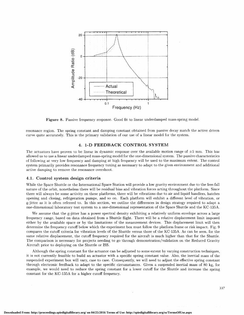
Figure 8. Passive frequency response. Good fit to linear underdamped mass-spring model.
resonance region. The spring constant and damping constant obtained from passive decay match the active drivencurve quite accurately. This is the primary validation of our use of a linear model for the system.
4. 1-D FEEDBACK CONTROL SYSTEMThe actuators have proven to be linear in dynamic response over the available motion range of mm. This hasallowed us to use a linear underdamped mass-spring model for the one-dimensional system. The passive characteristicsof following at very low frequency and damping at high frequency will be used to the maximum extent. The controlsystem primarily provides resonance frequency tuning as necessary to adapt to the given environment and additionalactive damping to remove the resonance overshoot.
4.1. Control system design criteriaWhile the Space Shuttle or the International Space Station will provide a low gravity environment due to the free-fallnature of the orbit, nonetheless there will be residual bias and vibration forces acting throughout the platform. Sincethere will always be some activity on these platforms, there will be vibrations due to air and liquid handlers, hatchesopening and closing, refrigeration pumps, and so on. Each platform will exhibit a different level of vibration, orgjitter as it is often referred to. In this section, we outline the differences in design strategy required to adapt aone-dimensional laboratory test system to a one-dimensional representation of the Space Shuttle and the KC-135A.
We assume that the g-jitter has a power spectral density exhibiting a relatively uniform envelope across a largefrequency range, based on data obtained from a Shuttle flight. There will be a relative displacement limit imposedeither by the available space or by the limitations of the measurement devices. This displacement limit will thendetermine the frequency cutoff below which the experiment box must follow the platform frame or risk impact. Fig. 9compares the cutoff criteria for vibration levels of the Shuttle versus those of the KC-135A. As can be seen, for thesame relative displacement, the cutoff frequency required for the aircraft is much higher than that for the Shuttle.The comparison is necessary for projects needing to go through demonstration/validation on the Reduced GravityAircraft prior to deploying on the Shuttle or 155.
Although the spring constant for the actuator can be adjusted to some extent by varying construction techniques,it is not currently feasible to build an actuator with a specific spring constant value. Also, the inertial mass of thesuspended experiment box will vary, case to case. Consequently, we will need to adjust the effective spring constantthrough electronic feedback to adapt to the specific circumstances. Given a suspended inertial mass of 80 kg, forexample, we would need to reduce the spring constant for a lower cutoff for the Shuttle and increase the springconstant for the KC-135A for a higher cutoff frequency.
337
cc-o
00a:U)00E
Frequency (Hz)
Downloaded From: http://proceedings.spiedigitallibrary.org/ on 04/25/2016 Terms of Use: http://spiedigitallibrary.org/ss/TermsOfUse.aspx

EC0
0>0ci)00E
Frequency (Hz)
Figure 9. Comparison of vibration environments.
While we will not be able to adjust the effective spring constant over the tremendous range implied by Fig. 9,we do want to allow as much dynamic range as possible. For demonstration tests on the KC-135A, we will beusing a significantly smaller suspended mass than anticipated for the Space Shuttle. The demonstration load will beconstrained to approximately 0.5 kg, while the loads on the Shuttle or 155 are expected to be on the order of 80 to400 kg.
4.2. Limitations of measurement devicesInitially, we assumed that accelerometers would be needed as the sensors for control feedback, but the results werehighly disappointing. Small, lightweight accelerometers did not have the sensitivity to monitor the low accelerationlevels desired and they exhibited a noise level exceeding the signal level desired. Larger, heavier, and more sensitiveaccelerometers are available, but they are expensive and add significant weight to the experiment. Additionally,positioning the accelerometers to obtain motion data in all six degrees of freedom proved to be a formidable task.
As a replacement to this, we devised a system using only position sensing devices (PSD's). If the only contactto the suspended experiment box is the actuator, then the force on the box is known from the extension of, andthe voltage applied to, the actuator and the acceleration can be computed. The addition of viscous friction can beincluded in the calculation by tracking the rate of change of extension.
For the current design, we found that low-cost, low-power diode lasers, combined with Hamamatsu two-dimensional12 mm x 12 mm PSD's give us measurement coverage over the displacement range of the actuators. The sensitivityof the PSD's is on the order of 6 /tm, which is on the order of amplitudes 40 dB down from the maximum. Thepass band of the control system is set to ignore any input with frequencies above the 6 jm cutoff. We are using thetwo-dimensional PSD even in the one-dimensional tests to monitor any out-of-plane motion of the pendulum. In thethree-dimensional system, the lasers and PSD's are arranged to form an orthogonal set of axes as will be discussedin Sect. 5 below.
4.3. Control modelThe actuator and mass are modeled as a linear mass-spring system as shown in Fig. 10. The variables D and Yrepresent the displacement of the platform frame and box, respectively, relative to some (unknown) inertial referenceframe. We are interested in the response of the inertial mass of the experiment box as a function of arbitrary motionof the Shuttle frame. The differential equation modeling this system is
(6)m rndt
338
0.1 1 10
Downloaded From: http://proceedings.spiedigitallibrary.org/ on 04/25/2016 Terms of Use: http://spiedigitallibrary.org/ss/TermsOfUse.aspx

D Y
PSD
Figure 11. One dimensional system block diagram.
with Ye th( equilibrium offset of the actuator, which is adjusted by the applied voltage, m is the inertial mass of thesuspended box, k is the passive spring constant, and b is the passive damping constant. As the actuators have beenshown to be highly linear, we approximate Ye as
Ye Yo + Vd, (7)
with Yo the equilibrium extension with no applied voltage, V the applied voltage and, d the piezoelectric constantfor the complete double bellows actuator stack.
The simplified control model block diagram for the one-dimensional case is shown in Fig. 11. The mass-spring andpiezoelectric effects of the actuator are accounted for in the block P . The passive viscous friction coupling betweenD and Y is outside the control system and is represented by the block F. The PSD is capable of measuring therelative displacement D-Y, and produces a signal of one volt per mm of relative displacement.
The block Kx represents the principal element of the control system. It consists of a bandpass filter to rejectfrequencies above and below the range needed for control and a Proportional-plus-Derivative (PD) control module.The proportional response couples to the displacement
x=D—Y+yo, (8)
and changes the effective spring constant. The derivative response is based on the time rate of change of the relativedisplacement dx/dt, and produces the desired additional (viscous-like) damping.
The output of Kx is scaled in volts per millimeter. The block Ka represents the high voltage amplifier needed toproduce a one millimeter extension for a one volt signal produced by the block Kx. Specifically, the amplification inKa is such that Kad = 1. For our prototype actuator stacks, the amplification would be 200 from Table 2. Withthe reduced electrical stiffness expected from improved manufacturing, this amplification may be reduced by half.
339
Piezoelectric Actuator(friction damping)
Figure 10. Mass-spring model.
Downloaded From: http://proceedings.spiedigitallibrary.org/ on 04/25/2016 Terms of Use: http://spiedigitallibrary.org/ss/TermsOfUse.aspx

By making the feedback voltage V, created by the block Kx, a linear function of x and dx/dt, with coefficientsK1 and K2, respectively, we get the form
= (±) (9)rn in Tn b iii
or = (1—K1)x+ (1K2). (10)TI' Tn b
With active control, the effective spring constant becomes kef k(1 _Ki) and the effective damping constantbecomes beff b(1 — K2k/b). Our goal is to drive the acceleration experienced by the suspended mass to aminimum, consistent with the constraint of not hitting the frame. For example, setting K1 = 1 and K2 = b/kwould make the actuator effectively disappear. The box would then not be under any control and would soon hit theframe. For this reason, the function Kx also contains bandpass filters to effect control only around the resonancefrequency.
4.4. Calculation of control variablesWithin the range of voltages allowed by the control system and the actuator, the effective spring constant can beadjusted to produce the desired response. The factors must be calculated for the given mass to be suspended andthe specific environment to be experienced. In all conceivable cases, the passive system will be underdamped, so weassume a passive resonance to exist at w = The proportional term, K1 , is calculated using the passivespring constant k for the actuator, the given inertial mass, m to be controlled, and a desired cutoff frequency,wc = 27rfc, determined from a graph such as Fig. 9. The desired effective spring constant is
keff wm, (11)
so that
K1 = 1 — (12)
The derivative term, K2, is then determined by calculating the critical damping factor
K2 (b — 2rnw) = — (13)
In practice, we have found that less than critical damping can improve the settling time while not exceedingthe acceptable overshoot limits. Additionally, the system response is sensitive to the settings of the bandpass filterlimits.
4.5. Active pendulum testsBoth analog and digital versions of the control model have been built. Testing primarily focused on the ability toinduce additional damping since time derivative circuits and algorithms can be excessively noisy. The results ofanalog and digital damping are shown in Fig. 12. The additional damping from the digital system is a result of thesharper frequency cutoff possible in the digital bandpass filters.
Without high pass filters the system would become friction dominated and would show only first order roll-offabove the cutoff. Without low pass filters, the system would risk saturation attempting to overcome the dc bias.The bandpass filter may need to contain up to fourth order high and low pass elements in the final system to avoidthese two problems.
4.6. Effect of non—zero dc bias accelerationsOn the Shuttle, offset dc bias accelerations on the order of less than 10 .tg are expected in the space lab module inthe cargo bay. For a suspended inertial mass of 80 kg, and four actuators affected by the displacement, we expectless than 0.1 mm offset from center. Up to 400 kg would still only produce approximately 1 mm offset, which wouldbe within tolerance if the effective spring constant were set slightly higher than optimum for no bias.
340
Downloaded From: http://proceedings.spiedigitallibrary.org/ on 04/25/2016 Terms of Use: http://spiedigitallibrary.org/ss/TermsOfUse.aspx

00cj
ci)00E
5. THREE DIMENSIONAL SYSTEM DESIGNThroughout development, we have adapted the design to the problems faced with a full six-degree of freedom system.[n particular, we have been developing a digital control system which can allow for non-symmetric mass distributionsby making use of the proportional adjustment capability in the control model. Knowing the inertia tensor, we canadjust the forces applied by the actuators to create the correct torques under varying spatial configurations due tothe motion without making small angle approximations.
5.1. Solution to 3-d geometry problemThe need for the small angle approximation was eliminated by solution of the geometry of the relative translationoffset and rotation of the box relative to the frame, This calculation has been demonstrated in a PC with up to500 updates per second without affecting other operations. This rate is well above that required for Space Shuttleapplications, but in the range required for demonstrations on the KC-135A.
5.1.1. Proposed flight test designThe next flight test configuration calls for 12 actuators arranged in three orthogonal planes of four actuators eacharound the suspended box. This provides for 24 umbilical signal lines, which is ample for readout of the three2-dimensional PSD's and a monitoring accelerometer on the box.
6. CONCLUSIONSWe have found that the prototype double-bellows actuator stacks behave reasonably in accordance with the analyticaland ANSYS simulation results. Although we could potentially achieve improved results with flat structures, theadditional manufacturing coriplexity of adding spacers does not seem justified, given the high degree of linearityobserved in the pre-curved structure we are using. We expect the greatest performance improvement from decreasingthe thickness of the epoxy layer between PVDF sheets constituting the bimorphs.
Testing in one dimension has verified that our actuators do produce a linear response and can effectively dampout vibrations above a specified cutoff frequency while following average platform motion below the cutoff. The useof a contact system such as this should be compared with non-contact proposals such as in Ref. 11, which discussesuse of magnetic actuators. Magnetic systems provide better passive damping in general but also tend to be heavierthan the small polymer devices described here. Also, non-contact systems force a separate solution to the umbilicalproblem.
341
Frequency (Hz)
Figure 12. Results with analog and digital damping.
Downloaded From: http://proceedings.spiedigitallibrary.org/ on 04/25/2016 Terms of Use: http://spiedigitallibrary.org/ss/TermsOfUse.aspx

The simplified control seems to couple to the physics of the motion quite adequately, at least in one dimension,but modeling indicates that the use of position control, pius derived velocity control , should be readily adapted tothe three-dimensional case as well.
ACKNOWLEDGMENTSThis work has been supported by NASA EPSCoR Grant NCC5-240 and by the Montana Space Grant Consortium.We would also like to acknowledge the assistance of D. G. Blair in the adaptation of the folded pendulum for ourpurposes.
REFERENCES1. V. H. Schmidt, J. Conant, G. Bohannan, J. Eckberg, S. Halko, .1. Hallenberg, C. Nelson. N. Peterson, C. Smith,
C. Thrasher, and B. Tikalsky, 'Piezoelectric polymer actuators for vibration suppression," Proc. of SPIE 3669,pp. 162—170, 1999.
2. G. Bohannan, V. H. Schmidt, D. Brandt, and M. Mooibro.ek, Piezoelectric polymer actuators for active vibra-tion isolation in space applications," Ferroelectrics 224, pp. 211—217, 1999.
3. D. S. Stampleman, 'Microgravity isolation mount based on piezoelectric film," Proc. SPIE 1898, pp. 716—731,1993.
4. B. A. Auld, Acoustic Fields and Waves in Solids, vol. 1, p. 271. Krieger Publishing Co., Malabar, FL, 2 ed.,1990.
5. H. Wang, M. Zhang, and L. E. Cross, "Piezoelectric, dielectric and elastic properties of poly(vinylidene fiuo-ride/trifluoroethylene)," J. Appl. Phys. 74, pp. 3394—3398, 1993.
6. A. E. Childs, "Modeling and analysis of thin-film, piezoelectric actuators," Master's thesis, Montana StateUniversity, 2000.
7. R. NI. Jones, Mechanics of Composite Materials, p. 40. McGraw-Hill Book Co., New York, 1975.8. D. I. Jones, "A control system for a microgravity isolation mount," Proc. 1990 Amer. Control Conf. , pp. 2601—
1606, 1990.9. D. G. Blair, J. Liu, and E. F. Moghaddam, "Performance of an ultra-low frequency folded pendulum," Phys.
Lett. A 193, pp. 223—226, 1994.10. J. Liu, J. Winterfiood, and D. G. Blair, "Transfer function of an ultra low frequency vibration isolation system,"
Rev. Sci. Instrum. 66, pp. 3216—3218, 1995.11. D. 1. Jones, "A control system for a microgravity isolation mount," IEEE Trans. Control Sys. Techn. 4, pp. 313—
325, 1996.
342
Downloaded From: http://proceedings.spiedigitallibrary.org/ on 04/25/2016 Terms of Use: http://spiedigitallibrary.org/ss/TermsOfUse.aspx


![Systems with piezoelectric actuators · 98 4. Systems with piezoelectric actuators Figure 4.3: Frequency response between A and B, with and without control [Is2 +Ω2 −g s+g ΦT(bkbT)Φ]z](https://static.fdocuments.net/doc/165x107/5e9d43522d66d6493c6f5244/systems-with-piezoelectric-actuators-98-4-systems-with-piezoelectric-actuators.jpg)


![Sensors and Actuators A: PhysicalS. Zhao, A. Erturk / Sensors and Actuators A 214 (2014) 58–65 59 on piezoelectric stacks [35–37]. Goldfarb and Jones [38] analyzed a piezoelectric](https://static.fdocuments.net/doc/165x107/603a6b20161d8859842d9f48/sensors-and-actuators-a-s-zhao-a-erturk-sensors-and-actuators-a-214-2014.jpg)
