PicoScope 2200 Series User's Guide - Pico Technology · PDF fileFor PicoScope models 2205 MSO,...
26
Copyright © 2008-2011 Pico Technology Limited. All rights reserved. PicoScope 2200 Series User's Guide ps2200.en-3 PC Oscilloscopes
Transcript of PicoScope 2200 Series User's Guide - Pico Technology · PDF fileFor PicoScope models 2205 MSO,...

Copyright © 2008-2011 Pico Technology Limited. All rights reserved.
PicoScope 2200 Series
User's Guide
ps2200.en-3
PC Oscilloscopes


IPicoScope 2200 Series User's Guide
Copyright © 2008-2011 Pico Technology Limited. All rights reserved. ps2200.en
Contents....................................................................................................................................11 Welcome
....................................................................................................................................22 Introduction
........................................................................................................................................21 Using this guide
........................................................................................................................................22 Safety symbols
........................................................................................................................................23 Safety warning
........................................................................................................................................34 Regulatory notices
........................................................................................................................................35 Software licence conditions
........................................................................................................................................46 Trademarks
........................................................................................................................................47 Warranty
........................................................................................................................................48 Company details
....................................................................................................................................53 Product information
........................................................................................................................................51 Model selector
........................................................................................................................................62 PicoScope 2200 Series Pack contents and Accessories
........................................................................................................................................73 PicoScope 2205 MSO Pack contents and Accessories
........................................................................................................................................74 System requirements
........................................................................................................................................85 Installation instructions
........................................................................................................................................96 Connections
......................................................................................................................................................................91 Connector diagrams (PicoScope 2204 to 2205) ......................................................................................................................................................................102 Connector diagrams (PicoScope 2205 MSO) ......................................................................................................................................................................113 Connector diagrams (PicoScope 2206 to 2208) ......................................................................................................................................................................114 Signal inputs ......................................................................................................................................................................115 Compensating probes ......................................................................................................................................................................126 AWG connector ......................................................................................................................................................................127 EXT connector ......................................................................................................................................................................128 USB port
....................................................................................................................................134 Glossary
....................................................................................................................................155 Appendix A: Declaration of Conformity
....................................................................................................................................19Index


PicoScope 2200 Series User's Guide 1
Copyright © 2008-2011 Pico Technology Limited. All rights reserved. ps2200.en
1 WelcomeThe PicoScope 2200 Oscilloscopes are compact unitsdesigned to replace traditional bench-top oscilloscopes costingmany times the price.
Here are some of the benefits provided by the PicoScope 2200 series:
Portability: Take the unit with you and plug it in to any Windows PC.Performance: Fast sampling from 100 MS/s to 1 GS/s, probe-tip bandwidths from10 MHz to 200 MHz and fast USB 2.0 interface. See Model Selector for details ofeach scope model.Mixed signal capability: Display analog and digital signals on the same timebasewith the PicoScope 2205 MSO.Flexibility: Use it as an oscilloscope, spectrum analyzer, or high-speed dataacquisition interface.Programmability: The PicoScope 2000 Series APIs let you write your ownprograms, in your chosen programming language, to control all the features of thescope.Long-term support: Software upgrades are available to download from ourwebsite. You can also call our specialists for technical support. You can continueto use both of these services free of charge for the lifetime of the product.Value for money: Buying a PicoScope PC Oscilloscope means that you don't haveto pay twice for all the features that you already have in your PC. The PicoScope2200 Series oscilloscope contains the special hardware you need and nothing more.Convenience: The software makes full use of the display, storage, user interfaceand networking built in to your PC.Dependability: Your scope is backed by a 5-year warranty against manufacturingfaults.
Additional information
For full technical specifications, see the following brochure and data sheet:
For PicoScope models 2203 to 2208: PicoScope 2000 Series Data Sheet (MM012)For PicoScope model 2205 MSO: PicoScope 2205 MSO Data Sheet (MM031)
The following manuals explain how to use the Application Programming Interface(API) to control a PicoScope 2200 Series Oscilloscope:
For PicoScope models 2203 to 2205: PicoScope 2000 Series Programmer's GuideFor PicoScope models 2205 MSO, and 2206 to 2208: PicoScope 2000 Series (A API)Programmer's Guide
These documents are available from http://www.picotech.com.
5
Introduction2
Copyright © 2008-2011 Pico Technology Limited. All rights reserved.ps2200.en
2 Introduction2.1 Using this guide
In this guide you will see symbols like this: This is the cross-reference symbol,and it indicates the number of a page on which you can find more information about atopic.
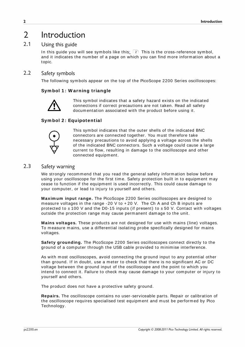
2.2 Safety symbolsThe following symbols appear on the top of the PicoScope 2200 Series oscilloscopes:
Symbol 1: Warning triangle
This symbol indicates that a safety hazard exists on the indicatedconnections if correct precautions are not taken. Read all safetydocumentation associated with the product before using it.
Symbol 2: Equipotential
This symbol indicates that the outer shells of the indicated BNCconnectors are connected together. You must therefore takenecessary precautions to avoid applying a voltage across the shellsof the indicated BNC connectors. Such a voltage could cause a largecurrent to flow, resulting in damage to the oscilloscope and otherconnected equipment.
2.3 Safety warningWe strongly recommend that you read the general safety information below beforeusing your oscilloscope for the first time. Safety protection built in to equipment maycease to function if the equipment is used incorrectly. This could cause damage toyour computer, or lead to injury to yourself and others.
Maximum input range. The PicoScope 2200 Series oscilloscopes are designed tomeasure voltages in the range -20 V to +20 V. The Ch A and Ch B inputs areprotected to ±100 V and the D0-15 inputs (if present) to ±50 V. Contact with voltagesoutside the protection range may cause permanent damage to the unit.
Mains voltages. These products are not designed for use with mains (line) voltages.To measure mains, use a differential isolating probe specifically designed for mainsvoltages.
Safety grounding. The PicoScope 2200 Series oscilloscopes connect directly to theground of a computer through the USB cable provided to minimise interference.
As with most oscilloscopes, avoid connecting the ground input to any potential otherthan ground. If in doubt, use a meter to check that there is no significant AC or DCvoltage between the ground input of the oscilloscope and the point to which youintend to connect it. Failure to check may cause damage to your computer or injury toyourself and others.
The product does not have a protective safety ground.
Repairs. The oscilloscope contains no user-serviceable parts. Repair or calibration ofthe oscilloscope requires specialised test equipment and must be performed by PicoTechnology.
2

PicoScope 2200 Series User's Guide 3
Copyright © 2008-2011 Pico Technology Limited. All rights reserved. ps2200.en
2.4 Regulatory noticesFCC Notice
This equipment has been tested to meet CFR47 (2006) Part 15 of the FCC limitsfor Class A equipment. These limits are designed to provide reasonable protectionagainst harmful interference when the equipment is operated in a commercialenvironment. This equipment generates, uses, and can radiate radio frequency energyand, if not installed and used in accordance with the instruction manual, may causeharmful interference to radio communications. Operation of this equipment in aresidential area is likely to cause harmful interference in which case the user will berequired to correct the interference at his or her own expense.
For safety and maintenance information see the safety warning .
CE Notice
The PicoScope 2200 PC Oscilloscopes meet the intent of the EMC directive 89/336/EEC and have been designed and tested to EN61326-1 (2006) Class A Emissionsand Immunity standard.
The PicoScope 2200 PC Oscilloscopes also meet the intent of the Low VoltageDirective and have been designed to meet the BS EN 61010-1:2001 IEC 61010-1:2001 (Safety requirements for electrical equipment for measurement, control andlaboratory use) standard.
2.5 Software licence conditionsThe software supplied with this product is licensed, not sold. Pico Technology Limitedgrants a licence to the person who installs this software, subject to the conditionslisted below.
Access. The licensee agrees to allow access to this software only to persons who havebeen informed of these conditions and agree to abide by them.
Usage. The software in this release is for use only with Pico products or with datacollected using Pico products.
Copyright. Pico Technology Limited claims the copyright of, and retains the rights to,all material (software, documents etc.) contained in this release. You may copy anddistribute the entire release in its original state, but must not copy individual itemswithin the release other than for backup purposes.
Liability. Pico Technology and its agents shall not be liable for any loss, damage orinjury, howsoever caused, related to the use of Pico Technology equipment orsoftware, unless excluded by statute.
Fitness for purpose. Because no two applications are the same, Pico Technologycannot guarantee that its equipment or software is suitable for a given application. Itis your responsibility, therefore, to ensure that the product is suitable for yourapplication.
Mission-critical applications. This software is intended for use on a computer thatmay be running other software products. For this reason, one of the conditions of thelicence is that it excludes usage in mission-critical applications; for example, lifesupport systems.
Viruses. This software was continuously monitored for viruses during production, butyou are responsible for virus-checking the software once it is installed.
2

Introduction4
Copyright © 2008-2011 Pico Technology Limited. All rights reserved.ps2200.en
Support. If you are dissatisfied with the performance of this software, please contactour technical support staff, who will try to fix the problem within a reasonable time. Ifyou are still dissatisfied, please return the product and software to your supplierwithin 14 days of purchase for a full refund.
Upgrades. We provide upgrades, free of charge, from our web site atwww.picotech.com. We reserve the right to charge for updates or replacements sentout on physical media.
2.6 TrademarksWindows is a registered trademark of Microsoft Corporation in the USA and othercountries.
Pico Technology Limited, PicoScope and PicoLog are trademarks of PicoTechnology, registered in the United Kingdom and other countries.
PicoScope and Pico Technology are registered in the U.S. Patent and TrademarkOffice.
2.7 WarrantyPico Technology warrants upon delivery, and for a period of 5 years unless otherwisestated from the date of delivery, that the Goods will be free from defects in materialand workmanship.
Pico Technology shall not be liable for a breach of the warranty if the defect has beencaused by fair wear and tear, wilful damage, negligence, abnormal working conditionsor failure to follow Pico Technology's spoken or written advice on the storage,installation, commissioning, use or maintenance of the Goods or (if no advice hasbeen given) good trade practice; or if the Customer alters or repairs such Goodswithout the written consent of Pico Technology.
2.8 Company detailsAddress: Pico Technology
James HouseColmworth Business ParkSt. NeotsCambridgeshirePE19 8YPUnited Kingdom
Phone: +44 (0) 1480 396 395Fax: +44 (0) 1480 396 296
Email: Technical Support: [email protected]: [email protected]
Web site: www.picotech.com
PicoScope 2200 Series User's Guide 5
Copyright © 2008-2011 Pico Technology Limited. All rights reserved. ps2200.en
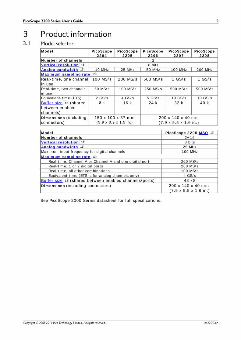
3 Product information3.1 Model selector
Model PicoScope2204
PicoScope2205
PicoScope2206
PicoScope2207
PicoScope2208
Number of channels 2
Vertical resolution 8 bits
Analog bandwidth 10 MHz 25 MHz 50 MHz 100 MHz 200 MHz
Maximum sampling rate
Real-time, one channelin use
100 MS/s 200 MS/s 500 MS/s 1 GS/s 1 GS/s
Real-time, two channelsin use
50 MS/s 100 MS/s 250 MS/s 500 MS/s 500 MS/s
Equivalent-time (ETS) 2 GS/s 4 GS/s 5 GS/s 10 GS/s 10 GS/s
Buffer size (sharedbetween enabledchannels)
8 k 16 k 24 k 32 k 40 k
Dimensions (includingconnectors)
150 x 100 x 37 mm(5.9 x 3.9 x 1.5 in.)
200 x 140 x 40 mm(7.9 x 5.5 x 1.6 in.)
Model PicoScope 2205 MSO
Number of channels 2+16
Vertical resolution 8 bits
Analog bandwidth 25 MHz
Maximum input frequency for digital channels 100 MHz
Maximum sampling rate
Real-time, Channel A or Channel A and one digital port 200 MS/s
Real-time, 1 or 2 digital ports 200 MS/s
Real-time, all other combinations 100 MS/s
Equivalent-time (ETS is for analog channels only) 4 GS/s
Buffer size (shared between enabled channels/ports) 48 kS
Dimensions (including connectors) 200 x 140 x 40 mm (7.9 x 5.5 x 1.6 in.)
See PicoScope 2000 Series datasheet for full specifications.
14
13
13
13
13
14
13
13
13

Product information6
Copyright © 2008-2011 Pico Technology Limited. All rights reserved.ps2200.en
3.2 PicoScope 2200 Series Pack contents and AccessoriesYour PicoScope 2200 Series oscilloscope package contains the following items:
Reordercode
Quantity Description
- 1 PicoScope 2200 Series oscilloscope
MI106 1 USB cable, for connection to the USB port on your PC
DI042 1 Software and Reference CD, with PicoScope and PicoLogsoftware, drivers , and example programs.
DO115 1 USB Oscilloscope Installation Guide
The following Accessories are available for your PicoScope 2200 Series oscilloscope:
Ordercode
Quantity Description
PP787 - 2 x 60 MHz MI007 probes (with probe pouch)
MI007 2 60 MHz probe
MI131 1 Probe pouch
14 13
13
PicoScope 2200 Series User's Guide 7
Copyright © 2008-2011 Pico Technology Limited. All rights reserved. ps2200.en
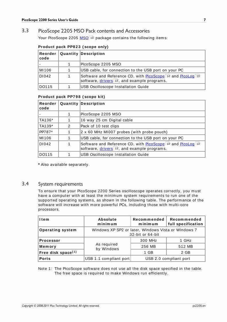
3.3 PicoScope 2205 MSO Pack contents and AccessoriesYour PicoScope 2205 MSO package contains the following items:
Product pack PP823 (scope only)
Reordercode
Quantity Description
- 1 PicoScope 2205 MSO
MI106 1 USB cable, for connection to the USB port on your PC
DI042 1 Software and Reference CD, with PicoScope and PicoLogsoftware, drivers , and example programs.
DO115 1 USB Oscilloscope Installation Guide
Product pack PP798 (scope kit)
Reordercode
Quantity Description
- 1 PicoScope 2205 MSO
TA136* 1 16 way 25 cm Digital cable
TA139* 2 Pack of 10 test clips
PP787* 1 2 x 60 MHz MI007 probes (with probe pouch)
MI106 1 USB cable, for connection to the USB port on your PC
DI042 1 Software and Reference CD, with PicoScope and PicoLogsoftware, drivers , and example programs.
DO115 1 USB Oscilloscope Installation Guide
*Also available separately.
3.4 System requirementsTo ensure that your PicoScope 2200 Series oscilloscope operates correctly, you musthave a computer with at least the minimum system requirements to run one of thesupported operating systems, as shown in the following table. The performance of thesoftware will increase with more powerful PCs, including those with multi-coreprocessors.
Item Absoluteminimum
Recommendedminimum
Recommendedfull specification
Operating system Windows XP SP2 or later, Windows Vista or Windows 732-bit or 64-bit
ProcessorAs required by Windows
300 MHz 1 GHz
Memory 256 MB 512 MB
Free disk space[1] 1 GB 2 GB
Ports USB 1.1 compliant port USB 2.0 compliant port
Note 1: The PicoScope software does not use all the disk space specified in the table.The free space is required to make Windows run efficiently.
13
14 13
13
14 13
13

Product information8
Copyright © 2008-2011 Pico Technology Limited. All rights reserved.ps2200.en
3.5 Installation instructions
IMPORTANTDo not connect your oscilloscope to the PC before you have installed the Pico
software.If you do, Windows might not recognise the scope device correctly.
Procedure
Follow the instructions in the Installation Guide included with your productpackage.Connect your PC Oscilloscope to the PC using the USB cable supplied.
Checking the installation
Once you have installed the software and connected the PC Oscilloscope to the PC,start the PicoScope software. PicoScope should now display any signal connected tothe scope inputs. If a probe is connected to your oscilloscope, you should see a small50 or 60 hertz noise signal in the oscilloscope window when you touch the probe tipwith your finger.
Moving your PicoScope PC Oscilloscope to another USB port
Windows XP SP2When you first installed the oscilloscope by plugging it into a USB port, Windowsassociated the Pico driver with that port. If you later move the oscilloscope to adifferent USB port, Windows will display the "New Hardware Found Wizard" again.When this occurs, just click "Next" in the wizard to repeat the installation. If Windowsgives a warning about Windows Logo Testing, click "Continue Anyway". As all thesoftware you need is already installed on your computer, there is no need to insert thePico Software CD again.
Windows Vista and Windows 7The process is automatic. When you move the device from one port to another,Windows displays an "Installing device driver software" message and then a"PicoScope 2000 series PC Oscilloscope" message. The PC Oscilloscope is then readyfor use.
14
14

PicoScope 2200 Series User's Guide 9
Copyright © 2008-2011 Pico Technology Limited. All rights reserved. ps2200.en
3.6 Connections
3.6.1 Connector diagrams (PicoScope 2204 to 2205)
A. Input channel AB. Input channel BC. AWG outputD. LED: shows when the oscilloscope is sampling dataE. USB port
11
11
12
12

Product information10
Copyright © 2008-2011 Pico Technology Limited. All rights reserved.ps2200.en
3.6.2 Connector diagrams (PicoScope 2205 MSO)
A. Input channel AB. Input channel BC. LED: shows when the oscilloscope is sampling dataD. Digital inputs D0-D15 (see below for further detail)E. USB portF. AWG output
Digital input connection (D)
The digital input pins of the 20-pin IDC header plug are shown below. The diagram isdrawn as you look at the front panel of the device.
11
11
12
12

PicoScope 2200 Series User's Guide 11
Copyright © 2008-2011 Pico Technology Limited. All rights reserved. ps2200.en
3.6.3 Connector diagrams (PicoScope 2206 to 2208)
A. Input channel AB. Input channel BC. EXT trigger inputD. GEN outputE. LED: shows when the oscilloscope is sampling dataF. USB port
3.6.4 Signal inputs
The PicoScope 2200 Series oscilloscopes have BNC oscilloscope connectors. Theinputs have an impedance of 1 M , so they are compatible with all standard scopeprobes including x10 attenuated types.
3.6.5 Compensating probes
We recommend that you compensate each oscilloscope probe before using it with yourPicoScope. Compensation instructions specific to the probe are included in the leafletsupplied with the probe.
Connecting a probe for compensation
1. Connect your probe to the signal generatoroutput as shown on the right.
2. Run the PicoScope software.
3. Click the AWG button and set the AWG togenerate a 1 kHz 1 volt square wave.
4. Follow the compensation (or 'trimming') instructions in the probe leaflet.
11
11
12
12
12
Product information12
Copyright © 2008-2011 Pico Technology Limited. All rights reserved.ps2200.en
3.6.6 AWG connector
The AWG connector (labelled GEN or Signal Out on some oscilloscopes) on the frontpanel carries the output of the oscilloscope's built-in signal generator, which cangenerate a number of built-in waveforms, as well as arbitrary waveforms from a user-defined table of data.
Instructions for use
If you are using the PicoScope 6 program, refer to the PicoScope 6 User's Guide forinformation on how to configure the signal generator.If you are writing your own software, refer to the relevant Programmer's Guide .
AWG output specifications
Refer to the PicoScope 2000 Series datasheet or the PicoScope 2205 MSOdatasheet, both available on our website.
3.6.7 EXT connector
The EXT (External) trigger input on some models can be used as a trigger source. Thetrigger source is selected using the trigger drop-down menu in the PicoScopesoftware, or using a function call if you are writing your own software.
The EXT input uses dedicated circuitry with a software-configurable threshold todetect a trigger signal. This has the advantage of freeing both analog channels forviewing signals. However, if trigger timing accuracy and resolution are critical, werecommend using the channel A or B input as the trigger source. These channels usedigital triggering, which is accurate to one sample period and has a vertical resolutionof 1 LSB.
3.6.8 USB port
Connect the oscilloscope's USB port to your PC's USB 2.0 port using the USB cablesupplied. The oscilloscope will work if connected to a USB 1.1 port but will operate atgreatly reduced speed.
1

PicoScope 2200 Series User's Guide 13
Copyright © 2008-2011 Pico Technology Limited. All rights reserved. ps2200.en
4 GlossaryAnalog bandwidth—The frequency at which the measured signal amplitude is3 decibels below the true signal amplitude.
Block mode—A fast data collection mode. The PicoScope software puts theoscilloscope into this mode to achieve the fastest possible sampling rates. Theoscilloscope collects data as fast as possible and then stops to transfer the data to thePC. During data transfer to the PC in block mode, the oscilloscope cannot sample datafrom its inputs.
Buffer size—The size of the oscilloscope's buffer memory, measured in samples. Thebuffer allows the oscilloscope to sample data faster than it can transfer it to thecomputer.
Coupling mode—To switch from AC coupling to DC coupling, or vice versa, select ACor DC from the control on the PicoScope toolbar. The AC setting filters out very low-frequency components of the input signal, including DC, and is suitable for viewingsmall AC signals superimposed on a DC or slowly changing offset. In this mode youcan measure the peak-to-peak amplitude of an AC signal but not its absolute value.Use the DC setting for measuring the absolute value of a signal.
Device Manager—Device Manager is a Windows program that displays the currenthardware configuration of your computer. On Windows XP or Vista, right-click on 'MyComputer,' choose 'Properties', then click the 'Hardware' tab and the 'Device Manager'button.
Driver—A program that controls a piece of hardware. The driver for the PicoScope2000 Series PC Oscilloscopes is supplied in the form of 32-bit Windows DLLs, ps2000.dll and ps2000a.dll. These are used by the PicoScope software to
control the oscilloscope.
ETS—Equivalent Time Sampling. Constructs a picture of a repetitive signal byaccumulating information over many similar wave cycles. This allows the oscilloscopeto create a composite cycle that has more samples, and therefore better timeresolution, than a single cycle. ETS cannot be used for one-shot signals.
Maximum sampling rate—A figure indicating the maximum number of samples theoscilloscope can acquire per second. The higher the sampling rate of the oscilloscope,the more accurate the representation of the high-frequency details in a fast signal.
MS/s—Millions of samples per second. Used to quantify the sampling rate of anoscilloscope.
MSO (Mixed signal oscilloscope). An oscilloscope that has both analog and digitalinputs.
Oversampling—A technique for reducing noise in sampled signals. Measurementsare taken more frequently than the requested sample rate, and then merged toproduce the required number of samples. If, as is usually the case, the signalcontains a small amount of noise, this technique can increase the effective verticalresolution of the oscilloscope.
PC Oscilloscope—A virtual instrument formed by connecting a PicoScope oscilloscopeto a computer running the PicoScope software.
PicoLog software—An application that can be used with selected Pico Technology PCoscilloscopes to turn your PC into a powerful data logger.
14
Glossary14
Copyright © 2008-2011 Pico Technology Limited. All rights reserved.ps2200.en
PicoScope software—A software program that accompanies all Pico PCOscilloscopes. It turns your PC into an oscilloscope, spectrum analyser, and meterdisplay.
Signal generator—Generates a waveform and outputs it on the BNC socket markedAWG, GEN or Signal Out. This output can be used to drive a test signal through aBNC cable into an external circuit or into one of the oscilloscope's input channels. ThePicoScope software allows the generator to output standard waveforms, such as sineand square waves, or arbitrary waveforms defined by the user.
Streaming mode—A data collection mode in which the oscilloscope samples data andreturns it to the computer in a continuous stream. This mode allows the capture ofmore data than will fit in the oscilloscope's memory buffer, at sampling rates over 1MS/s (PC dependent). The PicoScope program selects this mode for long timebases toenable the capture of very long sets of data.
Timebase—A timer that controls the speed at which the scope device captures data. At slow timebases this process is visible as PicoScope draws the trace across the scopeview from left to right, but at fast timebases PicoScope draws the whole trace in asingle operation. The timebase is measured in units of time (such as seconds) perdivision. There are ten divisions across the scope view, so the total time across thewidth of the view is ten times the "per division" setting.
USB 1.1—Universal Serial Bus (Full Speed). This is a standard port used to connectexternal devices to PCs. A typical USB 1.1 port supports a data transfer rate of 12megabits per second, so is much faster than an RS232 or 'COM' port.
USB 2.0—Universal Serial Bus (High Speed). This is a standard port used to connectexternal devices to PCs. A typical USB 2.0 port supports a data transfer rate 40 timesfaster than USB 1.1 when used with a USB 2.0 device, but can also be used with USB1.1 devices.
Vertical resolution—A value, in bits, indicating the precision with which theoscilloscope converts input voltages to digital values. Oversampling (see above) canimprove the effective vertical resolution.
Voltage range—The range of input voltages that the oscilloscope can measure. Forexample, a voltage range of ±100 mV means that the oscilloscope can measurevoltages between -100 mV and +100 mV. Input voltages outside this range will not bemeasured correctly, but will not damage the instrument as long as they remain withinthe protection limits stated in the specifications.

PicoScope 2200 Series User's Guide 15
Copyright © 2008-2011 Pico Technology Limited. All rights reserved. ps2200.en
5 Appendix A: Declaration of Conformity

Appendix A: Declaration of Conformity16
Copyright © 2008-2011 Pico Technology Limited. All rights reserved.ps2200.en

PicoScope 2200 Series User's Guide 17
Copyright © 2008-2011 Pico Technology Limited. All rights reserved. ps2200.en

PicoScope 2200 Series User's Guide 19
Copyright © 2008-2011 Pico Technology Limited. All rights reserved. ps2200.en
Index
AAccessories
PP787 7
TA136 7
TA139 7
Analog bandwidth 5
Arbitrary waveform generator 12
AWG connector 12
BBandwidth (analog) 5
BNC connector 11
Buffer size 5
CCalibration 2
CE notice 3
Company information 4
Connections 9, 10, 11
Contact details 4
DDimensions 5
Disk space 7
FFCC notice 3
GGEN connector 12
Grounding 2
IInput range, maximum 2
Installation 8
LLED 9, 10
MMains voltages 2
MSO 10
OOperating system 7
Oscilloscope probe 11
compensating 11
PPico Technical Support 4
PicoScope 2200 Series 1
PicoScope 2205 MSO 7
PicoScope software 8
Processor 7
RRegulatory notices 3
Repairs 2
Resolution, vertical 5
SSafety
symbols 2
warning 2
Sampling rate 5
Scope probe 11
Signal generator 11
output 12
Signal Out connector 12
Software licence conditions 3
System memory 7
System requirements 7
TTechnical support 4
Test equipment 2
Trademarks 4
UUSB port
changing 8
connecting 12
requirements 7
VVertical resolution 5

Index20
Copyright © 2008-2011 Pico Technology Limited. All rights reserved.ps2200.en
WWarranty 4
Windows, Microsoft 7

PicoScope 2200 Series User's Guide 21
Copyright © 2008-2011 Pico Technology Limited. All rights reserved. ps2200.en

Pico TechnologyJames House
Colmworth Business ParkST. NEOTS
CambridgeshirePE19 8YP
United KingdomTel: +44 (0) 1480 396 395Fax: +44 (0) 1480 396 296
www.picotech.com
Copyright © 2008-2011 Pico Technology Limited. All rights reserved.
ps2200.en-3
12.12.2011