PicoPacket Technical Reference Manual - Jive...
175
PicoPacket Technical Reference Manual PacComm Packet Radio Systems, Inc. 4413 N. Hesperides Street Tampa, FL 33614-7618 Telephone: (813) 874-2980 Facsimile: (813) 872-8696 Orders: (800) 486-7388 I;
Transcript of PicoPacket Technical Reference Manual - Jive...

PicoPacket Technical Reference
Manual
PacComm Packet Radio Systems, Inc. 4413 N. Hesperides Street Tampa, FL 33614-7618
Telephone: (813) 874-2980 Facsimile: (813) 872-8696
Orders: (800) 486-7388
I;

I : I I
I
I
~
I
I
I ! ,

Tltis entire manual is Copyright © 1996 by PacCol1ll1l Packet Radio Systems, Inc.
ALL RIGHTS RESERVED
Reproduction or translation of any pan of tltis work beyond that permitted by Sections 107 or 108 of tile 1976 United States Copyright Act (or it's legal successor) without the express permission of tile copyright owner is unlawful. Requests for permission to copy or for further information should be addressed to PacComm Packet Radio Systems, Inc.
Second Edition (Revised), October 1996

Table of Contents PacComm Warranties .................................................................................. 4 Repair Service ' .. : ........................................................................................... 4 United States Federal Communications Commission (FCC) Notice .............. 5 Introduction ................................................................................................. 6
About This Manual .................................................................................. 6 PicoPacket Features ................................................................................ ' 6 Network Firmware Compatibility ............................................................. 7 PicoPacket Finnware ............................................................................... 7 PicoPacket Models .................................................................................. 8 PicoPacket Summary ................................................................................ 8
Quick Start .................................................................................................. 9 Firmware ................................................................................................. 9 Baud Rates ............................................................................................... 9 Computer Connection ............................................................................. 9 Radio Connection ............................................... '" .................................. 9 Power. ..................................................................................................... 10 Software Requirements ........................................................................... 10
PacCOlnrn Firmware Support ............................................................... 10 APRS Quick Start .......................... " ....................................................... 11 GPS Receiver Operation .......................................................................... 13
If You Have Problems ................................................................................. 13 Hardware Description ................................................................................. 24
Design Considerations ............................................................................ 24 Modem Specifications ............................................................................. 24 RS-232-l Serial Port ............................................................................... 24 PicoPacket Block Diagram ...................................................................... 26
Detailed Circuit Description ....................................................................... 26 Oscillator ................................................................................................ 26 CPU Complex ......................................................................................... 26
Serial Port ................................................................................................... 26 Serial Port Signal Definitions .................................................................. 27 HDLC ..................................................................................................... 29 Watchdog Timer ..................................................................................... 29 Battery Backed RAM (bbRAM) PicoPacket Rev. 1.1 and 1.2 ................... 29 Battery Backed RAM (bbRAM) PicoPacket Rev. 1.31 ............................. 29 Power Supply PicoPacket Rev. 1.1 and 1.2 ............................................ ··29 Power Supply PicoPacketRev. 1.31... ...................................................... 29 Modem Transmit .................................................................................... 30 Modem Receive ...................................................................................... 30
Troubleshooting .......................................................................................... 30 General Tests .......................................................................................... 30 Digital Troubleshooting Techniques ........................................................ 31
General Cautions ................................................................................. 31
2
[-
I [

Power Supply ...................................................................................... 31 Typical Problems .................................................................................... 32
PicoPackel appears dead .................................................................... 32 The PicoPocket prints only gibberish ................................................. .34 Uncopyoble transmitted or received packets ....................................... 34 Can" get enough modem output ....................... . ..................... 34 DCD LED constantly flickers on and off............ . ...................... 34 Modem won't key tronsmi/ler ............................................................... 35 Transmitter locks in key down condition .............................................. 35
;
3

PacComm Warranties
PacComm Packet Radio Systems, Inc. (PacCornrn) warrants amateur products to be free from defects in materials and workmanship for a period of one year from the date o[purchase by the retail customer. During the warranty period. PacComm will, at its option, repair, replace, or refund the pmchasc price of any unit that it determines to be defeclive. This warranty does not apply to any product which has been modified, damaged through carelessness, misuse or neglect, used in conunercial service or which has been repaired outside PacCOIrun facihtie:-; without permission. Consequential damages are not covered. PacConun will refimd the purchase price (less shipping charges) for mllts returned within thirty days of purchase. Returned units are subject to a restocking fee jf not in like-new condition or if significant
customer support has been rendered during the trial period.
PacComm Packet Radio Systems makes no representation of warranties with respect to the contents hereof and specifically disclaims any implied warranties of merchantability or fitness for any particular purpose. F~er, PacConun Packet Radio SysLems reserves the right lo revise this publication, hardware, and software, and to make changes ill the content hereof without obligation of PacCOIlUll Packet Radio Systems to notify any person of such revisions or changes.
Repair Service
PacComm provides a rapid, low cost repair service for our products, whether in or out of warranly. Carefully pack the urtit and send it to the PacComrn address with a \\ritten description of the problems experienced and the repair service desired. Nonnal service turnarOlUld is WIder five days. We stock all parts for our units.
4 PicoPacket Teclmical Reference 2nd Ed. © 1996, PacComm, Inc.
L
I I

United States Federal Communications Commission (FCC) Notice
The FCC places limits on the strength or non-intentional signals emitted by electronic accessories which attach to, or install in, personal computers. These computer peripherals are classified as Class B Computing Devices. The following notice is required by United States Regulations.
i(i;Jli1Mi¥!!ri;!mi~WBRt#¢e~.[$'!i¥;(lUimQ;~!!»fi!E\11;ri@!!;I;M
This equipment has been tested and found to comply with the limits for a Class B computing device, pursuant to Part 15 of FCC Rules. These limits are designed to provide reasonable protection against such interference in a residential installation. This equipment generates, uses and can radiate radio frequency energy and, if not installed and used in accordance with the instructions, may cause harmful interference to radio communications. However, there is no guarantee that interference will not occur in a particular installation. If this equipmcllt does cause interference to radio or television reception, which can be detennined by tuming the eqUipment off and on, the user is encouraged to tIy to correct the interference by onc or more of the following measures:
• Reorient or relocate the receiving antenna. • Increase the separation between the equipment and receiver. • Connect the equipment into an outlet all a circuit different from that to which the
receiver is connected. • Consult t1le dealer or an experienced radiorrV technician for help.
You are also warned, that any changes to this certified device will void your legal right to operate it. All interface cables to and from this device must be shielded.
End of required message.
PicoPacket Teclmical Reference 2nd Ed. © 1996, PacComm, Inc. 5

Introduction
Introduction
About This Manual
This manual applies to the PacConUl1 PicoPacket Packet Controller. It covers the physical. electrical, and mechanical aspects of the PicoPacket. Instructions' for operating the PicoPacket flllllware are contained in the Operating Manual ~ . for PacCOIllm Packet Controllers.
Be sure to read any Errata before operating the PicoPa\.:keL
A Quick Start section is provided following this introduction to assist experienced operators in PicoPacket operation.
The Jwuper and Solder Pad Section has a full technical explanation of the fiUlction and default setting of eachjwnper and solder pad.
A full schematic and circuit description are provided to assist technically soplu;;ticatcu users 10 make the best use ofPicoPacket features.
TIle tenns "computer" and "tenninal" are used interchangeably to refer--lo the device used to comlUunic(lte with the packet controller.
PicoPackct Features
The PicoPackel uses modem surface mount teclutology for compact size and excellent performance and value.
• "TAPR" style commands plus many PacCOlmn additions. • On-Line HELP makes lhis the perfect beginner's me. So easy to learn' • The PacConIDl Personal Message System (PMS). A self-contained message
system (maIlbox) with all the slate-of-the-art features. About 12k storage is available in Ihe 32k model, over 64k storage in 128k model.
• renninal programs for hath DOS and Willdows™ included. • GPS ready. Full support for APRS (the Automalic Position Reporting System)
with either single or dual port models. The PicoPacket works with APRS tluough either the standard single serial port or the optional second serial port The PicoPacket and APRS work together so that when the PicoPackct with a GPS receiver (iutemal or external) is controlled by APRS it sends no beacons except as cOlfUllanded by APRS. When ille APRS computer is disconnected, the PicoPacket automatically becomes a <<tracker" sending out location beacons at specified intervals.
• Comes with Inslructi'on Manual, schematic, Quick Command listing, RS-232 cable and DE-9S adapter, two wltenninated radio cables, and power cord.
• RJ-45 radio cable is made of "real" copper wire and solders easily to radio connectors.
6 PicoPacket Technical Reference 2nd Ed. © 1996, PacComm, Inc.
L

Introduction • Optional full-time GPS port (second serial port) also provides rea1~time clock
and 128k RAM. • Intemal GPS. A Trimble SVee6-CM3 GPS Receiver is fitted directly into the
PicoPacket. • Battery Pack model. Built-in charger, and a case back with rails to carry the
slide-onlslide-off battery pack. • 10MHz rated CMOS Z-181 (80181) macro-cell MPU.
• Z-80 compatible CPU. • 8530 SCC HDLC port. • Two asynchronous serial UART ports. • GPS Power management functions.
• 32k or 128k battery backed RAM. (512k RAM on special order). • EPROM and RAM are socketed for ease ill upgrading fmnware and increasing
memory. • Crystal controlled IC modem supports standard 1200/2200Hz lones used for
1200 baud AFSK packet. • Connect, Status, PIT, and Carrier Detect LEDs. • Black anodized aluminum case I x 2.5 x 3.25 inches.
• All metal construction is resistant to electronic emanations. • Hardware clock support standard on all Internal GPS and Second Serial Port
Models. • Open Squelch DCD circuit built in to every PicoPackel. • Typical power Consumption 50mA @ 8-14 VDC. Power saving features reduce
the average current draw significantly.
Network Firmware Compatibility
TIle PicoPacket is not intended for network use. No provisions have been made to accommodate clUTently available network firmware. The PicoPacket is NOT TNC-2 compatible.
PicoPacket Firmware
PacConun fmilware is based on code licensed-from Tucson Amateur Packet Radio Corp. (TAPR).
PacConun finnware supports most TAPR conunands, but internally it is much, much different than TAPR code. There are many additional commands and features and we are continually expanding the fWlctionality of the code.
In addition. the PacComm code has been extellsively re-written for faster execution and greater reliability.
PicoPacket Technical Reference 2nd Ed. © 1996, PacCOInm, Inc. 7

Introduction
PicoPacket Models
The PicoPacket is offered in several different models. These' models are manufactured from the same circuit board design, but the case and components fitted are not the same.
PicoPacket Models • PicoPacket Standard Model w/32K RAM/Open Squelch DCD • PicoPacket Standard Model wIJ28K RAMlOpen Squelch DCD • PicoPacket wlBattery Packl32K RAMlOpen Squelch DCD • PicoPacket wlBattery Packl128K RAMlOpen Squelch DCD • PicoPacket wl2nd Serial PorUReal Time Ciockll28K RAMlOpen Squelch DCD • PicoPacket wlBatlery Packl2nd Serial PorUReal Time Ciockll28K RAMlOpen
SquelchDCD • PicoPacket wlIntemal GPS/2nd Serial PorUReal Time Clockl128K RAMlOpen
SquelchDCD • PicoPacket wlIntemal GPSll3atlery Packl2nd 'Serial PorUReal Time Ciockll28K
RAMlOpen Squelch DCD
PicoPacket Summary
The PacColluu PicoPacket is a compact, robust, and itlcxpensive packet controller. The modern sw-face mount technology used in the PicoPacket design provides durability and ensures many years of reliable service. The Battery Pack, 2nd Serial Port, Open Squelch DCD, and full GPS support options provide flexibility, allowing the PicoPacket to be tailored to U,e specific cods of the individuaL
8 PicoPacket Teclmical Referenr" 2nd Ed. © 1996, PacComll1, Inc. I I I

Quick Start
Quick Start
Firmware
The PicoPacket is provided wiill PacComm's TAPR based 1NC fmnware. The commands are fully docwneuted in the Operating Manual for PacComm Packet Controllers and are provided in concise form on the Command Reference Card.
New to packet, or an· old· timer who has forgotten a few conunands? Just type Help followed by a command name (or part of a conunand name) and receive the correct spelling, shortest abbreviation, default value( s), acceptable value( s), and a short
explanation of its function.
Baud Rates
PicoPacket baud rates are set by the BAUD command. Rates from 300 to 9600 (9.6kb) are selectable for the terminal. The PicoPacket serial port baud rate is defaulted to 9600 bps. The radio port is set at 1200 bps and may not be altered.
To cll'lIIge the data rates, type BAUD at the cOImmUld prompt (cmd:) and press the letter corresponding to the data rate desired. If you want the new rate to take cfieet ilmnediately, type 'X'. Inunediately change the data rate of the terminal or conununication program to match. If you want the new data rate to take effect after the RESTART command is given, type 'Z'.
Computer Connection
The PicoPacket RS-2J2 COlUlector is wired as DCE. The RS-232 cable should be wired for connection from a computer (DIE) to a modem (DGE). The cable and adapter supplied with the PicoPacket should cormeet directly to a standard pinout PC serial port without modification. To connect to a 25 pin COlmector > u~e a pre-made adapter or see the Serial Port interfacing section of thi.s manual (Page 16).
Radio Connection
The PicoPacket allows the transmit signal to be applied directly to the microphone and draws received audio [rom the radio's speaker cOllnectioll. The PicoPacket should easily interface to any voice grade radio.
Radio connector pinout is on page 17.
PicoPacket Technical Reference 2nd Ed. © 1996, PacComm, Inc. 9

Quick Start Power
The PicoPacket operates from a nominal 6 VDe. Input voltage may range from 6.0 to 14.5 volts. The center pin of the power receptacle is positive. A diode protects the PicoPacket from reversed polarity power connections. 111e power consumption of the PicoPacket Standard Model is approximately 50 mAo
Software Requirements
The PicoPacket is supplied with both DOS and Windows'fM communication programs.
The Windows™ program is a demonstration version of tile excellent packet terminal program~ PacketPet for Wlndows'IM.. which is sold by PacComm.
'The DOS program is a public domain program which is simple and easy to use.
If you are not using a PC. any software that enables your computer to operate with an ordinary telephone modem should work for testing and operating your PicoPacket.
The PacComm telephone BBS [(813) 874-3078] has a variety of programs which may be downlO!ided at no charge. Also check your local packet radio BBS, local telephone BBS, pJJ.blic domain software vendors in computer magazines, at hamfests, computer shows, and local flea markets.
PacComm Firmware Support
PacComm welcomes problem reports when our firmware does not appear to fUllction properly. Call, fax, or write for a software discrepancy form which will help you record a11 the information necessary for us to research the problem.
PacConun supports the current fumware release, and the most recent prior release for a period of six months after it has been superseded.
Bug reports on earlier releases are solicited, but the bug ftxes will only be applied to the current release. PacConull policy is to constantly improve the pcrfonnance and features of our fmnware, but to limit the frequency of fumware releases to a modest rate.
'10 PicoPackct Technical Reference 2nd Ed. © 1996, PacComm, Inc.

Quick Start
APRS Quick Start
The PicoPackel is fiIlly APRS (Automatic Posilion Reporting System) compatible. TIle following fealures and connnands h.ve been added 10 the PicoPacket to enllance APRS support.
• 111C MONitor command remains operative when GPS IS sct to ON; i.e. the monitor function is on or otT depending on the setting of MON regardless of whether GPS is on or oJ1
• The MYAlias command allows the assignment of an alternative callsign (in addition to the callsign specified in MY CALL) for digipeater use. The PicoPacket fitmware includes the MYAlias conulland along with three additional callsign alias fields; MYlalias, MY2alias, and MYJalias. The fldditional callsign alias fields [\U1ction like the MYAlias conunand.
• The LTEXT serves as a buffer to contain the most current data string from the attached GPS or LORAN receiver. The GPSTEXT command (see Operating .iWalJual for PacComm Packet Controllers) specifies which string is automatically entered into the L TEXT. The PicoPacket fmllware includes three addition. I text buffers, Lltext, L2text, aad LJtext, which operate like L 1EXT. The Lltext, L2text,aad L3lext allow you to place supplementory data strings (i.e. NMEA, weatiler tex!, etc.) in these fields, in addition to Ule data string automatically placed in the L1EXT (usually $GPGGA). When the PicoPackel sees the character specified in the LGEtchar connnaad il dumps the contents of tile L1EXT, Lltex~ L2tcx!, aad L3text fields to the tennin.!'
• LGltext, LG2text, aad LGJte,,1 are fields to be used for generating a history file in the Personal Message System. These fields are not yet operative but-have been set aside for inclusion in a future fmnware release.
• ELOc (Echo Location) is an ON/OFF comlnand. When ELO is OFF, the LOCATION beacon operates as described in the Operating Instructions. When ELO is ON, it causes tile current contents of the Location Text field (LTEXT) to be sent out U,e serial port (RS-232 or RS-232-1) as ASCII lext instead of being sent out the radio port as a beacon. The tuning is controlled by the LOCA nON conunand. just as fOf the beacon. This command is useful when you desire to locally view the GPS output at a specified interval.
• The LGEtchar conunand selects the character used to trigger the dumping of the. contents of the L1EXT, LI1EXT, L21EXT, and L31EXT ftelds to tile termina!. The default value of the LGEtchar is $00 wlllch disables this fWlction. LGEtchar should be set to S05 for use with APRS Release 74d and later. This command eliminates the need for a serial porL splitter cable when used with the two~port PicoPacket.
PicoPacket Technical Reference 2nd Ed. © 1996, PacComm, Inc. II

Quick Start
When the LGEtchar is set 10 any value olher than $00, the INC walches for the specifted character in the serial port input stream (RS-232-1 on the two-port PicoPackel). When this character is detecled, it is discarded from the data stream, and the conlents (if NOT blank) of the fOil[ L TEXT ftelds are dumped to tile serial port and the "current cycle" of the LOCATION timer is sent as if a LOCATION beacon had just been sent. If APRS queries the PicoPacket witil tile LGEtchar intennittently (sometimes more. sometimes Less them the LOCA110N timer) tilen tile PicoPacket will also send the LOCATION heaeons intemlittcntly.
TIlis supports the "F8" function key in APRS which requests the latest fix from the attached GPS It allows automatic conversion from an MRS tracker (which is the rue emitting location beacons) to an APRS mobile (which is a computer emitting location beacons via a WC). If you plug in an APRS computer which is configured correctly to work with the PicoPacket, the TNC is preempted from sending location beacons lUltil the computer is disconnected.
The LGEtehar command should he left set to $00 on PicoPacket models WitilOut a second serial port or an internal GPS receiver. Note that Ole LGEtchar command will work.in Transparent mode. but transparency is LOST, since the LGE character is deleted from the outgoing data stream
• TIle GPS command. On single port PieoPacket models, tile GPS connnand operates as specified in the Operating Manual. On PicoPacket models witll a Second Serial Port or Internal GPS, the GPS functions are always active. The GPS conmlll11d selects which port is used as input for the GPS data, using the computer port as reference; e.g. OPS OFF (nomllli setting) expects GPS data from the second serial port (RS-232-2 or internal GPS) , wllile GPS ON expects GPS data from the prinulfy serial port (RS-232-1).
• Note that "GPS data" does not have t9 be from a GPS receiver and may actually be data from a weather station or other telemetry device.
• PicoPacket fmnware responds to tile ? APRS? query by sendi.ng a location beacon. This occurs at a random time between 10 and 150 seconds after ?APRS? is heard (as tile first characters in a data packet).
12 PicoPacket Teclmicai Reference 2nd Ed. © 1996, PacComm, Inc.
1-

Quick Start
GPS Receiver Operation
PacComm has ~n successfully integrating GPS technology into packet controllers for several years, the insight gained from "this experience has been incorporated into the PicoPacket design. An Iriternal GPS receiver is offered as an option on the PicoPacket, and the PicoPaeket with Second Serial Port Model accepts GPS infonnation as input into the second serial port. This section will attempt to give an overview of GPS receiver operation to those w1familiar with this exciting teclmology
that is making it's way into the world of packet radio.
Those new to the use of the Global Positioning System will notice that it sometimes takes longer than other to get a fix. Let's look at wh~' sometimes fixes appear relatively quickly. and somelimes they do not.
First, the GPS receiver is exactly that - a receiver, and as a receiver it must rely on infonuation gleaned from satellites to do it's job. It starts out not knowing where on earth it is. After about 28 seconds it will know fi'om any ONE of the available satellites what the date and time is. It will then search around trying each one of the satellite codes (there are 24 ) in all attempt to get good signals from FOUR satellites.
Thjs may take several minutes in this first attempt. TIle receiver may derive a fix rapidly. BUT do not switch otT the receiver, as it has not assimilated all the data it needs.
The GPS receiver relies on the satellites to furnish it with an ALMANAC which it stores in RAM. It takes a full 15 minutes to receive the ALMANAC. ·This allows the
receiver (once it knows the time and date) to predict which satellites are going to be visible to it the next time it is powered up. Some flne tuning detail. called the ephemeris, is also downloaded and stored in the receiver's RAM. The NEXT time the receiver is turned on, if the satellite signals are good, it will obtain a fix inuch faster than wheu initially used. Subsequent warm starts should take between 30 seconds and 4 minutes to obtain a fix, depending on system geometry. However. if the receiver has moved significantly over the ground while the unit was switched off
(more tluUl300 miles) orhas lost RAM battery back-up, the almanac will incorrectly predict the satellites in view and will possibly panic after a few minutes and go into
the full sky search routine described above.
If You Have Problems
If you do not succeed in getting your PicoPacket packet controller operating with this
Quick Start section then you should read the Operating Manual aud all of the
Tcchnical Reference Manual for mOre detailed infonuation. Please make an effort to research llie problem in the manuals which arc provided
before telephoning for assistance. Many customers telephone for technical support
only to fmd lheir question is clearly answered in Ule manual.
PicoPacket Technical Reference 2nd Ed. © 1996, PacCOImn, Inc. 13

Quick Slart
Uyau call for technical assistance. have the following Information "ready:
I. The model n.me or number of the p.ckel controller you are using, e.g. PicoP.ckel w/Second Seri.l Port or PiooP.cket wlIntemal GPS Receiver, elc.
2. Details about the computer you are using, such as: • lbe communications program you are using. • Accessory cards installed in your computer. • The number of pins on your serial port COIUleclof.
3. Details about the radio you are using, such as: • Brand and model number. • Type of radio interface cable beil'g used.
4. The current jumper and solder pad setlings on the PicoP.cke! board and auy daughler boards.
14 PicoPacket Technical Reference 2nd Ed. © 1996, PacComm, Inc.

Installation and Operation
Installation and Operation
TItis section provides infonnation about the radio selection, switches, connectors, LEDs, jumper settings, and adjustments of the PicoPacket packet coritrolIer.
Radio Interface The modem in the PicoPacket is designed for cOIUlection to the microphone and speaker/headphone connections of a radio. Signal connections required to the radio are Transmit Audio to the microphone, Receive Audio direct from the receiver, PIT (radio keying) and Growld.
A resistive PIT connection is provided for use WiUl many hand held radios. TIUs RPIT output simplifies connecting a PicoPacket to hand held radios (which typically have a combined mic input and keying line) by routing the PIT sigualthrough a 2.7k resistor and placing this output on a separate pin of the RJ-45 radio COJUlector (13).
Switches, LEDs, and Connectors
Power Switch The first generation of the PicoPacket (Rev. 1.1) has no power switch. Plug in the power plug to turn the unit on; remove the power plug to turn the Pico off.
PicoPacket Revs. 1.2 aud later have a two position power switch. The position closest to the Output Adjust trimpot is off, and the position closest to the edge of the cabinet is on.
PicoPacket BatLef)1 Pack models (Revs. 1.2 and later) use a three position pov.'er switch. The position closest to lhe Output Adjust trimpot is for battery charging, the center position is ofT, and the position closest to the edge of the cabinet is on.
LEDs {mfiN~ii~¥{t ::,~, ~~ ,~.; <:~; .. :LL.J§.::'~~. ~ .. ' '~; ,~/ ; ~~' ~~ v -; ,'; < X~\:~,i}%lSM~&m~mEf1{m~M~~~ The Connect LED (CON) illuminates when an AX.2S cOIUlection exists on the selected stream for that port. (See multi-connection explanation in the Operating
The Status LED (STA) illuminates whenever an AX.2S frame has been sent but not yet acknowledged. If a connection is to be tenninated (DISCONNEClED) and the . STA LED is lit, some frames which were sent but notacknowledged may be lost. The STA LED will blink at about a I Hz rate if there is au unread message in the Personal Message System (PMS).
PicoPacket Technical Reference 2nd Ed. © 1996, PacComm, Inc. 15

Installation and Operation
~~_t~f1~~~fKmf:~~MIii~~t~~~~~~~Hr:@rI:A~:;~:::'{~:~t;he::~:':~~~:~:;}:~:::::;::::;it~~tmt:I~M\;Ntf10.fNJ}WtWm~p~M~it~i~i~ The Push To Talk LED (PIT) illuminates whenever the PicoPacket activates the radio ke)'ins line.
i!~~~~'!!:;\;~:f!~;~f~!~~;!:!f=:!;!!!!i!!i!!;;!l::~!:!;l!1i!!~!!f signal of the proper baud_rate_ The LED may occasionally flicker due to noise on the radio circuit. . ,
Internal Connectors g~Eiult;,\liEii!l@llim? t@':Y'::¥Y:'iFi';;;;Wt1l.1@'m:ii1I%lfWWI ;:;£ J2 and-P3 are expansion connectors used to support a daughterboard implementing such features as the second serial port, real time clock. and internal GPS receiver.
External Connectors Every PicoPacket is provided with two unterminated radio cables, a power connector with attached cable, and an RS-232 cable with DE-9 adapter.
Power Connector TIle power connecto~ is a ].3 nun diameter coaxial type. The sleeve is negali ve and the center pin is positive. Extra power COIUlectors arc available at electronic or audio equipment stores or from PacComm.
Use caution when attachillg a strange wall-transformer' power supply to the PicoPacket. Many power supplies are wired with the sleeve positive and center pin negative.
PI - RS-232 Serial Port Connector Tne PicoPacket RS-232 computer connector is an RJ-4-5-6 female COIUlector ",ired as a modem (DCE). See the Serial Port section for more infonnation (Page 16).
iilwlllltt¢I~llr;mBu{fit&JI!!!;I!i1i\lIMliiil RS-232 level flow control signal out of the PicoPacket. Bldicates whether the TNC is
i~li$J~li~li~~~'ti~fjllii&;i,l:;li1!! Receive Data (RXD) RS-232 level data OUT OF the PicoPacket to the tenninal.
1tt!ii\t%.@t_!iiI!mJ~]';I%iJI#'ii RS-232 level data INTO the PicoPacket from the tenninal.
1\lqAI%1(lijf!ljnm($~gij)lR:mM;jili;m;!l; RS-232 level flow control signal into the
Pin-out for b OU, RJ -45
Connectors.Looking into the sockets on. th.e PicoPacket.
PicoPacket. Indicates the attached computer wants to send data to the 1Ne.
!If!~¥tlmMtit.~B!!~~~Ii~:f~~t@~!!I&tl~;@!!~;11i;~~~!@3ji~-t1i{~~i.ft~if:#~~t!;Ii~;\tg~@N:~l!
Installation and .Operation
Combined signal and frame growld.
relftlg\fNIQ;~.iii_ljlll!111@iiil;'i;ill!f;!Ii'b1A;S~!i;~U~"j}i!;;;;iilllill;wlt!i;;! On the first generation PicoPacket (Rev. 1.1) this pin is not connected. On subsequent versions (Rev. 1.2 and later) this pin provides a signal to the DIE
,Jt~~~I.~.I) .. Ill.~t.0~.!.'!~~e.Ill .. i~.C<)~~~!e.<l'!?~?0e.r.s~~i?.!.'(o.!I~I0.e.) ..................... _ .... _ .......... , ! Note: DSR and DTR lines are not implemented on llie PicoPacket. If your computer! ! requires a DSR signal to operate properly. tie pin 4 of the DE-9 adapter to pin 6!
U~~~~.~.~.~~.~~p'~.~':'~~?~.I.~.~¥:_ ..... ..... , .................................... _ ................................................................ i
J2 Radio Conne.ctor Connections to the radio are made via J2 a RJ-45-6 receptacle • ~-
Atinco, 100M, Standard, RXAto Tandy, Yae:s:u PlugTiP~ 3Jmm
6 No COl:U'l.cction • ~ I'lL'-OND 10 ---I$;'Wl j
5 RXAudio Input Sleeve
4 PIT 35mm TUIR·PTT 3 Ground GRN = f!!ll! ~~. to ring 2 TXAudio H-~~~~I . 25'il _ Altemative wiring fOI
1 R-PTT ICOMW2A 27k 1 - single stereo plug
PicoPacket ---3.5rnm.
R.PTTtOPlugSl"V'~ ~ 1XA to Plug Ring
Kenwood 2Jrnrn
GND to PlugSleev8 !ft*,,", Iil!l , RXA to Plug Tip
---."."-,._-'"--.-.-,--- _., •.•.• _ ..• _ .• ···_'w.-~_:_·_:.:_ .-,; :-:-,.:.,:>,-,
IgJ«!!ttfl~l!filiijfi}illKtiJiiiW!~J~!~!~W~~1~!i~~t~~;i~W!ff;ftmii¥!iJ.f;~~I@~@!~ltW!;!t!i!r$tlr!M~fm:tMt@MW This line is connected internally to llie PIT line by a 2700 ohm resistor simplifY connecting to hand held radios. The circuit for cOlUlecting to such a radio is shown above. Note that both the capacitor and resistor are provided INSIDE the PicoPacket. To key a conventional radio attach the radio PIT line to PicoPacket pin4: ........ w .......... .
i~~~!!!;ii!~~~~!1!!!!!!~;;:!:i~~:;;!:!i!:!:!;~~~!!;!;~;1i~!;::;i!~;;~!{;~~r ir~~lIfiuiiJ;I[;irii!iiiiijii!tBiiiill;J&;iiii;{I%iljl;timS;;;;;;;:,X,;;;;;:&;,1i;A ~iiiJ*!~~0$~[d;li1;jii~!;i~;;jil;iii~i t)Eil'1iiMl!i!tfii]@jii)!;;;::}!!!!Ml COlUlect to the radio PIT Ime. Uses open drain keying which assumes the keying Jine
lilillii)tii~iii;[~i·rlj;ltf~,;;i~~];;;;,;;mliMf0'H;!f;M;1!r .. ;;';li;'ii/i!inl Signal input from radio speaker or headphone jack.
PicoPacket Technical Reference 2nd Ed. © 1996. PacConun. Inc. 17

Installation and Operation
NIC Receive Audio (RXA)
NOlITl.li PIT (PH) Gro\lIl.d(OND) Transmil.Audio(TXA) Rehslive PTT (R-PT1)
RS-232-2 (Second Serial Port) ~ An additional RS-232 port is provided on PicoPaeket Models with the Second Serial Port Option. The second serial port is accessed via • 3.5mm stereo jack labeled RS-232-2. The cOIUlections to the mating plug are as shown. A schematic of the cable is
011111 rrom Device Into p;;,, ____ J
Oall frOln Pica Into Dcvicc---~
provided on the rear of the PicoPacket schematic.
The second serial port allows for an external GPS or weather station to be altached to the PicoPacket.
Adjustments
Modem Adjustments MitfJ.{ttfJnRijt"f.~U¥lMlRt~f@tK _'1H}r:~\:>·;;\";~;·~·~~:~~:;~:~~~tmt~·:.t{t.M]W~1~~t~{:;:~~~"':~' .~:;::;~:~~k:l':,::::: The PicoPacket modem requires from 25 to 700 millivolts audio input. For normal operalion, the level of oulput provided by the FM receiver should be adjusted to a low to medium level. There is no input level adjustment on the PicoPacket Revs. 1.2 and earlier. On the PicoPaeket Rev. 1.31 an Audio Input Impedance jumper (JPRA) has been included. If JPRA is open a 47k resistor (RI6) is placed in the line for high
impedance audio input, if JPRA is closed this resistor is bypassed for speaker audio input. If desired, adjust the radio's output audio level to approximately 50 mV with the aid of a high inlpedance voluneter or oscilloscope.
Use the following procedure: COIUlect the PicoPacket and radio, turn on the PicoPacket and computer and start the computer communications program. I. Enter the command CAL «CR» and the letters "KD" to cause the PicoPacket to
key the radio with a steady dual tone.
rNo"iE;"Th~"~~'i~i~d'~~"t~~~~'~ji'i'~~~~"th~'PIT'~i'~~;;i~"~~"~~~~t'~n~~"~p~~~~~~~~l'~'j;~'l ~ 60 seconds. Type 'K' «CR» to restart the procedure. TIle tones may be checked j jindividually by typing K' mstead ofXD' in the procedure above. Pressing the spacej : bar will switch to the opposite tone. The output level is set by adjusting lrimpot VR3: j which is accessible through the rear panel opening marked Output Adjust. i •••••••••••••••••••••••••• , ••••••••••••••••••••••••••••••••••••••••••••••••••••••••••••••••••••••••••••••••••••••••••••••••••• , ........................................ 1
18 PicoPacket Technical Reference 2nd Ed. © 1996, PacComm, Inc.

Installation and Operation
2. With the PicoPacket keying the transmitter adjust Ute transmit audio level trimpot VR3 while observing a service monitor or deviation meter tuned to the transmitting frequency. Set the deviation for 2.8 to 3.5 kHz.
3. Type the command Q to unkey tile transmitter.
~.................. ................................... ....................... . ......................................... : ~ NOTE: Too low is better than too high a drive level. A 1ugh drive level causes over- i j deviation, Ulmecessary interferencc, and makes the signal less copyable. Running 5 j ! kHz deviation, for example, can result in a loss of 6 to 20 dB in signal to noise ~ 1 perfonnance on the circuit. ~ "' .......................................... ,.......................................................... . .............................................. .
tMa\t~m;Rftl.\tff!M{iit4jljllDMilllinl;iH;;;;!m&E !M;;;;:hHcII;;'{1iint You should not adjust these trimpots unless advised to do so by factory technical
support personnel
rNOiii;Th~·d;~;;.;;;·;;;;i~~·:d;~;;;;b~~·ili~··p;~~P~~k~;··R~~.;:·3;··o;;·U;~·fi~~i;;;;d: j second generation PicoPacket (Revs. 1.1 and 1.2) the designator and fWlction of the j ~ trimpots remains the same as the PicoPacket Rev. 1.31, however their location is j ; reversed. 1 , ................................................................................................................................................................. .
Trimpot VRl is the modem bias
adjustment. The procedure below is used at tile factory. While observing pin 11 of the 3105 modem IC (U2) adjust VRI to glve a reading of 2.65 to 2.70 vde on should produce satisfactory
resulls.
19i!tij"~tmN.~!&mr&#.m#Il:\~i\tj¥!@!:.;.;;·;;:;...,;;Eiii'ni...;;;;!: if; Use an oscilloscope or voltmeter to monitor the signal level on· pin 14 of the TCM3105 modem IC. With no input signal present adjust VR2 to give a 'low' TTL signal. Set VR2 to the point just below the transition to a 'high' level. Confmn thal the state of pin 14 goes high when an input signal is applied to the PicoPacket. Jftlle
required equipment is not available, adjust trirnpot VR2 to cause the DCD LED to ilhuninate when a weak input signal is present to the modem, and to go out when no
signal is present.
The above carrier detect level adjustment is for PicoPacket models without the Open
Squeeh DCD circuit. Ensure that tlle solder pad SP7 is jumpered from 2-3 to use the
modem (TCM-3!05) carrier detect.
PicoPacket Tecllllical Reference 2nd Ed. © 1996, PacComm, Inc. 19

Installation and Operation
;ufWagl;ȴ~WifiI&tmi\\\l1\$t!liijat{mlif1fillt]Sqijll~i;;QmniMlJlijlll;MI11;ln;il Note: The Carrier Detect Level Adjustment for PicoPackets wiih the Open Squelch DCD circuit installed is IN ADDITION TO the Carrier Detect Level Adjustment described above. Therefore to adjust the carrier detect level of a PicoPacket with ihe open squelch DCD circuit installed, you must first jumper solder pad SP7 from 2-3 and follow ihe procedures above to set the I modem (TCM-3105) carrier detect. Then remove the solder bridge from pads ~ 2-3 of the solder pad SP7 and jumper SP7 from 1-2, you are thus prepared 10 set the open squelch DCD carrier detect level. The solder pads SP19 and SP20 are used to adjust lhe carrier level delect when the XR2211 DCD circuit is installed. When the XR2211 circuit is installed, jumper SP20 closed and use a frequency counter to observe the output at Pin 3 of the XR2211. Adjust VR4 for an output at Pin 3 of 1700Hz. After completing the adjustment, jumper SP19 closed and open SP20.
20 PicoPaeket Technical Reference 2nd Ed. © 1996, PaeComm, Inc.

PicoPacket Jumper and Solder Pad Definitions
Jumper and Solder Pad Definitions
Detailed jwnper and solder pad definitions for all revisions of the PicoPackel, including options and factory default settings are described below.
,~I;lf!iiJ.f.~f~W;q;'t_;I.;jii;\;.;j;;~ljr;l;;jii,I,;tj .. j;:itrNj.:li!iP~(~!flt~i,m~i::l;mi,;i,1;ll! i Open Back-up battery disabled, RAM contents losl at power-ofl~ i ! Closed Back-up baltery enabled, RAM contents preserved. ! ............................................................................................................. , ................... , ..................................... . JPB makes or breaks the battery back-up connection to the RAM which preserves RAM contents when ~wer to the PicoPacket is off.
(f»B.,ljjIWl!~)I!l.uJjmm~!llm~~ .. ;J.;';;IIi.ill;,ij:ili;;iJ:;;i,.;.ji:riJ!ll~~!t.1;m~m.::li!!ilitl;!, i Open High Impedance audio input. .
i .. (;.I~~~~ ...... s.!"'IlI.<e.~.~~.~i~ .. irlp~t........................ .......................................................... . ...... .1
,&.;,;~;;~i~i;lii~;t;iiltffu\\\i\iii'li~jll~i!l~~r~jifi,\~£~ .. i!iI;.1.i;:;l!,\@1fu, i This solder pad applies modem the DCD signal to the DCD LED. Do not change the i ! default setting of SP3. This solder pad is not available on the PicoPacket Rev. 1. 31. ~
1~~i%ii!;:!I!~~!!:~:~~;~!~!~~;~;!;~!~~;:!!});tKi;i;;1i.~E4~jfii~~~.~.~i9W!;;!;llt;;j ! 2-3 > 32K RAM 'default for RAM sizes greater tlum 32K ! J$.i~1jl+i;Il;~f.$.J'Il:wB\;;:i;;&!i1il;f~fJi;;iiilr;;{tir;iijjl;:;i;:&:;.\!l!!l;p.jt~W.tt\[email protected]:!!~!!Ji: i 1-2 32K EPROM (27C256) i i 2-3 Reserved for future use. i i2-4 64K EPROM (27C512)' default setting i
:[§g$ltt!ji;iI~i~1»!&W;4tl~~ii})~i@:~!f~lij;ii;li;:;fwi;;l;i;;!1i~({Ml!lilIHtf~ffi;;iiWft~: : Open IN4001 Diode (D6) installed' defaull for Baltery Pack Models i ! Closed D6 not installed' default for ALL models EXCEPT Battery Pack Models : ·Noii;·Thi~ .. ~~id~ .. p·~d·;,;;~;~~f~~~·;~·~~·ih~ .. RXD·s·~i~~tj~~;·~-;;P;~~P~~k~;" Revs. 1.1 and 1.2. On those models SP] should remain Open.
i~~t,li;lrii~:;!~!!:!:j!!~~f!!!~:;:!:~:::~,ft4J1!tll~~~;;i;;@1&il{1ill;iti i 2-3 Applies AI9 to adapter board for expanded memory. ! .:3.g$.m~iffr~!~flip.m~~~N1jffi~itf£~fJj~t1t1.t1lt~]~~~:Jji~~~~j~Jf{}1~ij~~~~~ti~t~!i)~!jJr~~j!~~1j»IJ.Ml.fl!_~~~~~!);i!l~N~~~1j~~; ! Open 07 installed for additional reverse power protection. ! ! Closed D7 not installed. i ................................................................................ ,....................... • ......................................... , ••• 1
NOTE; This solder pad was available on the PicoPacket Rev. 1.2 only.
,1lt~t\WWt¥~i1!~litflfim~fl:~j]:fitii.\\ij~l;:jHjliii;1;)tiip,~r4MnnQi~i:i.;;!lljj!!Mi:ii, ! Open U9 installed (Battery Pack Models ONLY). i ! Closed U9 not installed. .. ............................. ! ·Noiii; .. ·U9·;~·U;~ .. 8 .. ·~~it;~~~i~;;;;~~~d·;~·~h;;;g~·ii;~ .. B~tt~ry Pack Models of the
PicoPacket line. If a battery board is NOT installed, U9 should be vacant and SP6 shonld be closed. This solder pad is not available on the PicoPacket Rev. 1. L
PicoPacket Technical fu:ference 2nd Ed.© 1996, PacCOImn 21

PicoPackct Jumper and Solder Pad Definitipns
j§»l~:f~*Mtj~i~»g»I~lflnil~~Wf~~j~~j~~fM!:~i~J~!~a?fli~t~j~m~~K}~~1j~fm;ijm:}lli!U~t"I~1~~;~~~~lfltt:}tr@~t: : 1-2 Open Squelch DCD (XR2211) circuit installed. i ,2-3 310S DCD (XR2211 NOT insta!1ed). : "Noii>ihi~"~~id';;P;;';C;;;;-d"ih~~"U;~'XiU2'ii"~;;~~;t";~'~~;'~~~;i~bl~'~~"ih~'fi~~t' generation PicoPacket (Rev. 1.1). On the PiooPacket Rev. 1.2 the XR2211 circuit was
offered as an option and built on a daughter board. All models of the PicoPacket Rev. 1-' 1.3 I include the XR2211 DCD circuit. :$Ulj!1$l?mliii~6~iQ~Ja\tit!Jlf$l;WlU~($;!;;f:l!»Miilijt~\i$l¥i8.&mW;il!;1# SPI9 and SP20 are used to adjust the carrier detect level on PicoPackets with the Open Squech!)cD circuit installed. Refer to tlle In<tallatioll and Operation section of this manual for
NOTE: SP7;I;~st be ~~I 10 i:3' il-tl;~ Xiuiii DCD ~ircuit is in~I~lled. These i are not available on the PicoPacket Rev. 1.1 and 1.2. !
. - . ~ '.:.. " ": . '. ....
The following solder pad jumpers are available on the GPSIMEMlRTC circuit board,
which is a "daughter" board interfaced with certain models of the PicoPackeL 'The
GPSIMEM/RTC board acts as an internal GPS carrier board, memory expansion board (SI2kb), provides real-time-clock features, and second serial port option. The
GPSIMEMlRTC board is present on all second serial port and intemal GPS models
and it's coutignration is model dependent.
\$r.NIl}.I84t!vg;iWfl!iiiim$~li!!!l~li·('ilijJjl!i{i!!!!!i@;!li~tA1i,\ftimll~;jHllll;;;f!i Open GPS requires passive antclUla
:-~A~~~ ...... g~§..!'~9.~~~~.~~!.i.::~ .. ~~.~.~~ ..... " ............. " ........................................................................ ! : Note: TIle Trimble SVee6-CM3 offered with the Intemal GPS model of the! 1 PicoPacket requires an aeH ve antenna. i TiRw;Jffli\j!tiUlliv:Aif~ffi§~w@YIW;iiw;;l;{f;jl!jlWiH;lliW;u~r4'1lifi);filiilil]'ir;iwiltlif Open GPSIMEMIRTC board powered by Svdc from PicoPackel. Closed PicoPacket nflwered by Svdc from GPSIMEMIRTC board. fN~t~: .. ·ii;;;·~~id~~P';;~···i;ci~~~d .. f~;·pi~~p~~k~;···;;;n;;t;;;;~i'GPS"';;;;-d"op;;~"'f~;i j PicoPacket w/Second Serial Port models. TIus solder pad is available on the second i ! generation and beyond of the GPSIMEMIRTC (Rev. 1.1 and later) circuit board. ! $i~\:i~irtlI~niijJjf8w¢i:~'\t;:jW;'f~'iiE\;;;@&§'{1@lf;ilit@Uil11~Ilf)\)@i!@;;;fffi 1-2 LED Dl or D3 indicates power applied to unit
}.:~ .......... J,.Il.p..P..1.~!.P.3...ll,l~.ic.~t~.s.<3.I.'.S..!!"'~i~i'.'8} .. ?,.l~.~r.e..""t~1.1i.~~~ .............................. . j Note: This solder pad is defaulted from 2'3 for PicoPacket wllntemal GPS and; 1 PicoPacket w/Secolld Senal Port models. This solder pad is available on the second j j generation and beyond of the GPSIMEMIRTC (Rev. 1.1 and later) circuit board. i
'[§H!;ITMiij:i:·gliWi\ijlMi1!~g~~ij!fJyl!'~W'ti!lli;r!@iii'ilittl»Jf~\lwijim~mjl;;:i!lMiif Open GPS power management features enabled Closed GPS power management features disabled
22 PicoPackct Technical Reference 2nd Ed.© 1996, PacComm

PicoPacket Jumper and Solder Pad Definitions
rN~t~;·"Thi·~·";~i"d~~·.· p~"X~'''~~~ii~'bi~'''~~ ··th~ .. ·ti~· 'g~~~~;ti~~"'~~d"~y~~d'''~f 'th~'i i GPSfMEMIRTC (Revs. 1.2 and later) circuit board. i
'§R~l!ti!I1;!1;Uj~JDfti(fE'Il\'m(~~lfil!!t;jlli;fliiff;:¥!i!li!;i!1;;!!1'~&f4li't~\11~;;;iiii;\il:1~liilf 1-2 OPS data routed to PicoPacket from internal GPS receiver. 2-3 GPS data routed to PicoPacket from external GPS receiver or other
.............t~Ie.~,..try.~.ev.i~~,........................................................ ............................. , l Note: This solder pad MUST be used in conjunction with SP4. TIlis solder pad is! iavail.ble on the third generatIOn and beyond of the GPSfMEMIRTC (Revs. 1.2 andi iIater) circuit board. 1 ·f$it~!1ili;gll~iti[(i[iiilWl~iil'ii'l':f!i!m@ifj·';l;i;;~ll·IIlllit@jHrza!11!1;lili!![i\f,@11l 1-2 GPS data routed to intemal GPS from PicoPacket. 2-3 GPS data routed to external GPS or other teleme~ device from PicoPacket.
~ ................................................................................................................................................................ : ... : i Note: This solder pad MUST be used in conjwlction with SFl TIils solder pad IS i 1 available on the tllird generation and beyond of the GPSfMEMIRTC (Revs. 1.2 and 1 j later) circuit board. j
'$~il;j;~i;;m;11!yw[~~)[j);;~~;·;;;jlirii'i;;;!;)iiii;1·j]);fjjiffir;)1i;'j;I;1'iill!lfi!l!lft;QW[fiil111[;);;';;fill[ii' Open PicoPacket w/2nd Serial Port Option
.qo.~~ ..... Xi,o.r.~~!<.e.\"::'f11t"'.I1~I .. qr.~.9.p.tio.J1........ ...................... . .............................. , ! Note: TItis solder pad is available on Ule forth generation and beyond of the!. 1 GPSfMEMiRTC (Revs. 1.3 and later) circuit board. .
'mttitHj[ii)lifil1i4t~iis~litjili;@\tijl:1\l;11:mf;:1·;lji;;1;M;:!i;~N{\JI(('(QIM\ml';(¥;·i;";[ Open RS-232 level output at RS-232-2.
,q".s.~c,I ..... m!ey.~I .. ~.lltp".t .. a.t .. ~s.:2.}~:.2. ........................................................................... , ~ Note: TIris solder pad is available on the second generation and beyond of the j ! GPSfMEMIRTC (Rev. 1.1 and later) circuit board. TI,;S solder pad MUST be used in! 1 conjunction with TTL2; e.g. they are either BOTH open or BOTH closed. If'TIL 1 ! levels are desired, DOTH TTLl and T1L2 must be closed, and the MAX-232 chiP! 1 (UI) must NOT be installed 011 the GPSfMEMIRTC board. i ':w11t\~l\'ltimijj!\\lt@~;t!i~¢li!!';;'i'i·'t;;¥ii'.m::i;\!@i)i\\:if:::·iif·lp~f4~tf;·'Q~·¢~::@!:·::i:;il'il':;r Open RS-232 level output at RS-232-2.
,q".s.~c,I ..... m.l~y~l.o.".tp.~~!'ct}~~:2.3?:?:.................. ......... . ..... . 1 Note: TItis solder pad is available on the second generation and beyond of the 1 GPSfMEMIRTC (Rev. 1.1 and later) circuit board. This solder pad MUST be used in 1 conjunction. with TTLI; _e.g. they are either Born open or BOTH closed. If TIL ! levels are desired, BOTH TILl and TIL2 niust be closed, and the MAX-232 chip 1 (UI) must NOT be installed on the GPSfMEMIRTC board . ......................................................................................................................................................................
PicoPacket Technical Reference 2nd Ed.© 1996, PacCOlnm 23

Hardware Description
Hardware Description
This section includes detailed hardware specifications and a functional ~escription of the hardware design oftlle PicoPacket packet controller.
Design Considerations
TI,e PicoPacket incorporates a Z-181 microprocessor;Wt which provides enhanced feature capability while allowing backwards compatibility with the Z-80 CPU. This innovation pennits PacConun to build upon existing finnware and provide additional features, such as:
eLarger memory mapping capabilities . • 2 full-duplex UART serial ports. -Low power consumption . • Portable, lightweight desigu . • MultiRlayer printed circuit board to improve noise immunity . • Surface mOWlt technology allows for compact design without sacrificing reliability.
eRemovable battery pack option . • Full APRS (Automatic Position Reporting System) support. eIntemal or ex1ernal GPS support options.
Modem Specifications
The PicePacket modem is a nell 202 compliant AFSK desigu based on the Texas Instruments TCM3105. The chip uses switched capacitor filtering to achieve sharp filtering and noise immunity.
111is same modem design has been used in tens of thousands of other PacComm lNes. Tones of 1200 and 2200 Hz are used for standard amateur radio operation at 1200 baud.
RS-232-1 Serial POIi
The PicoPacket packet controller communicates with the computer or tenninal through a serial port using RR-232 level siguals.
The PacComm PicoPacket packet controller supports asynchronous computer tenninal baud rates of 300 to 9600. The purt supports standard parity options as well as 7- or 8-bit character lengths.
Factory settings are 9600 baud, eight bit word-length, no parity find one stop bit.
24 PicoPacket Technical Manual 2nd Ed. © 1996, PacComm, Inc.
1-

Hardware Description The serial port COImector on the PicoPacket packet controller is on the front panel marked RS·232 or RS·232·1. 'Jbe pins on the serial port connector of packet controller that must be cOIlllecled are shown in the following table. This is conunollly called a three·wire RS·232 cable.
RS-2nSeriaJ Port "3 Wire" Cable Wiriog for DE-9 Computer
Computer DE-9 PicoPacket 5 and shell ......................................... 5 2 ......................................................... 2 3 ...... , .................................................. 3
The packet controller is configured as Data Communications Equipment (DCE), the technical teon for. an RS-232C mOdem. Most colnputers and terminals are configured as Data Terminal Equipment (DTE).
~ome computers require that Clear to Send (CIS) of the computer serial port connector (pin 5 of a DB·25 or pin S of a DE-9) be connected to an appropriate signal. Others may rcqnire cOlmections for Data Carrier Detect (DCD) (pin S/pin I) and Data Temlina! Ready (DTR) (pin 20/pin 4). To accomplish this on the PicoPacket jumper the computer's input and output signals on DB·25 pins 415 (DE·9 pins 7/S), and on DB·25 pins 6/8/20 (DE·9 pins 61l/4) in addition to the cOlmections shown in the «3 wire" RS~232 diagranl above.
Jumpering RTSfCTS and DTRfDSRfDCD at the Computer End DB-25 DE-9
4 __ 5 7 __ S 6, __ S __ 20 1 __ 4 __ 6
Computers with nonstandard RS-232 serial ports must meet the following conditions: • Voltage levels sent by the computer must be greater than +3 volts in one state
and less than -3 volts in the other state. • 'The signal polarity must conform to the RS·232 standard, i.e. the low voltage
state is a logical "1" and the high-voltage state is a logical "0". Make 01' buy a cable that provides the following connections: • The computer serial port common (ground) pin must be tied to the PicoPacket
serial port connector pin 5. • The signal line that sends data from the computer must be tied to the PicoPacket
COIDlector pin 3.
• TIle pin on WhlCh the computer receives data must be tied to the PicoPacket connector pin 2.
TIle dOCllluentation provided with the computer or it's accessory serial port shOUld clarify any requirements for additional signals.
PicoPacket Technical M.1nual2nd Ed. © 1996, PacComm, Inc. 25

Hardware Description
PicoPacket Block Diagram
A block diagram of the major PicoPacket fimctions is presented below.
RAM 32kS to 512kS
ROM 32kS to 12ekS
Z·181 Microprocessor unit containing
CPU, Oscillator, 2 ch.nnel UART, 1 channel Serial Communication
Controller, Parallell UO,
and Counter-Timer.
Detailed Circuit Description
Oscillator
OpUon.1 2nd Seri.1 Por1lRS·232 Levsl
Shifters
A 9.21 :MI-Iz crystal is divided in two by the intemal CPU oscillator to 'provide a stable 4.6 MHz CPU clock source.
CPU Complex
The microprocessor, Ul, is a CMOS Z·18l(84l80·1O) . Both asynchronous sorial and HDLC funclions are perfonned by Ul.
The EPROM U7 (27C5l2; 64k b)1es) contains all Ule finnwarc, addressed as two banks of 0 lo 7FFF.
The 32k x 8 or l28k x 8 RAM, U6, holds all bunOred data and battery backed parameters. RAM is addressed from 8000 to jiFFY
Each memory device's chip select is provided by the processor and the RAM chip select is also butlered by a power failure detection circuit. When voltage is low or removed, the RAM enlers low power mode, drawing approximately two micro·amps while retaining memory contents,
Serial Port
UL provides for asynchronous conununicalions through a RS232 driver and receiver (U5), RS232 signals are inlerfaced via an RJ-45,..6 connector with a DeE pinout Band rotes of 300, 1200,2400,4800, and 9600 are supported.
26 PicoPacket Technical M311ua12nd Ed. © 1996, PacComm, Inc.
I~

Hardware Description
Serial Port Signal Definitions
Ibis section describes the signals on the packet controlIer's serial port COlUlCclor.
Since the pins are defmed with respect to rhe Dala Tcnninal Equipment (DTE) (computer) end of the circuit, anu the packet ccntro1lee is wired as Data Communications Equipment (DCE) (modem), some standard pin names appear to be the reverse of the packet controller function. Read this section careful1y if you are experiencing dift1culty communicating \\lith the PicoPacket VIa the serial port. • Frame Ground (FG) is provided for attachment to the chass~s of the packet
controller and the chassis of the attached computer lenninal. This is common to Ule signal ground on the PicoPacket.
• Transmit Data (TXD) is an input line. to the packet controller on which the attached computer terminal device sends data.
• Receive Data (RXD) is an output line from the PicoPacket on which it sends data to the attached computer terminal device,
• ,- Request to Send (RTS) is an input to the packet controller signaling that the attached computer.tenninal device is ready to accept data from the PicoPacket. This line is used for hardware flow control.
• . Clear To Send (CTS) is an output from the packet controller signaling the attacheq .computer tenninal device to send data to the PicoPacket. TIlis line is used for hardware flow control.
• Signal Ground (SG) is the common, or return, path for all signals between the PicoPackel and. the attached computer tenninal device. It is common with the frame ground.
• DCD (Data C'arrier Detect) is an oulput from the packet controller signaling the attached computer that the PicoPacket is in a connected (on-line) state.
The table below provides a cross reference to the pinouts of the standard 25 pin cOIUlector, the industry standard 9 pin COllnector as used on many computers and terminals, and the RJ-45, DE-9P, DE-9S, and DB-2SS cOlUlectors used on PacComm products. Note that connecting a DIE device to a DeE device using either 2S pin connectors or 9 pin connectors at both ends of the cable provides a 'straight throUghl wiring of pin numbers, Le. connect column 1 to column 4 OR connect COiUllUl 2 to column 3. However. when a 25 pin connector and 9 pin comlector are used on the same cable, i.e. column 1 to colwnn 3, several pairs of signal lines IDusL be crossed.
PicoPackct Teclmical Manual 2nd Ed. © 1996, PacCOlmn, Inc. 27

Hardware Description Serial Port
The CTS and RTS lines of the PiwPacket serial port (labeled Plan the circuit board and RS-232 on the front panel) are used by the PicoPacket firmware for hardware "handshaking" to control the flow of data between the computer and the packet controller.
The computer terminal indicates it is ready to receive data from the PicoPacket by asserting its Request To Send (RTS) signal on PI pin 4. The packet controller will send data when RTS is asserted (if there is data to be sent). If the computer is not ready to receive data, it negates (makes false) RTS to thePicoPacket Thus, data nnw from the packet controller!l! tl.e computer is controlled by the use of the RTS lille.
TIle packet controller aSsclts its Clear To Send (CIS) output, PI pin 5, whenever it is ready to receive data from the computer. lfthe PicoPacket's buffcr~ ml, it will negate CTS, signaling the computer to stop sending data. lhe packet controller will assert CIS when it is again ready to receive data from the computer. Thus, data flow from the computer !Q the packet controller is regulated by the use of the CTS lille. 'The CIS line is always toggled, even if "software flow control" is enabled in Uris directioll.
If "software flow control" is preferred, or if the computer tenninal serial YO port does not implement CTSIRTS and DTRfDSR handshaking, then a three wire cable should be used. If Ulese RS-232 control lines are not comlected they will be pulled up (and thus asserted) by resistors at the PicoPacket end and proper operation will result. However, a nOll~standard serial port may use some pins for other purposes,
28 PicoPacket Teclmical Manual 2nd Ed. © 1996, PacConun, Inc.

Hardware Description
such as supplying power to 8 peripheral device, so be sure that the system either implements the CTS, RTS and DSR handshake or has no COlUlections to these pins of PI whatsoever. Note that reference to RS-232C "compatibility" or the presence of a DB-25 or DE-9 type connector does not guarantee that you have a standard R8-232C serial port!
HDLe
The HDLC fiUlclion is pcrfonned by the lolSI (UI) which communicates to the onbuard integrated circuit modem to provide 1200 baud AF8K.
Watchdog Timer
UI (Z-lSI) RTSA (pin 56) provides tile signal tila! ultimately keys the radio transmitter. When the PicoPacket is transmitting, RTSA goes low, which is fed through C6 to a Schmitt trigger gate (U3 pin 13) which turns on the PTT LED (04) and rehlffiS a high signal to O,e gate of a VNIO (FET) transistor (Q). TItis high state on the VNIO gate causes it to conduct to ground, keying the transmitter. TIle RTSA low 10 C6 starts it charging tluough R4 to Vcc. If the RTSA signal remains low more than 60 seconds, C6 reaches the Sclunitt trigger voltage, causing the gate (U3) to tum 011 the FIT LED and the VNlO, tlms lillkel'ing the transmitter.
Battery Backed RAM (bbRAM) PicoPacket Rev_ 1_1 and 1_2
The entire 32K or 12SK of RAM (U6) is backed up with a 3 volt liOtimn battery. The 081210 (U4) is also battery powered keeping "chip enable" (Pin 22) of the RAM disabled (high) during periods of low power to the PicoPacket (typically 6.5 volts and below).
Battery Backed RAM (bbRAM) PicoPacket Rev_ 1.31
'The entire 32K or 12SK. of RAM (U6) is backed up with u 3 volt Iitltimn battery. "Cltip Enable" (Pin 22) of the RAM is disabled (high) by UlOD (74HC32) when VCC falls below 4.75Y. When Voc falls below 4.75 volts, the reset (Pin I) output of the MC34064 (U4) goes low. TIlls signal is used to disable the RAM "chip select" and to hole the CPU ina "reset"state until Vee returns.
Power Supply PlcoPacket Rev. 1.1 and 1.2
The incoming positive voltage is routed tiuough a diode (OS) for reverse polarity protection. It feeds regulator US (LM2931). The battery circuit is isolateu by U4 (081210) to keep the RAM powered when-ever JPB is installed. The PicoPacket requires approximately 50 mA at 9-14 VDC.
Power Supply PicoPacket Rev. 1.31
The incoming positive voltage is routed through a diode (D8) for reverse polarity protection. It feeds regulator US (LM2931). The battery circuit is isolated bl' 07 and
PicoPacket Technical Manual 2nd Ed. © 1996, PacComm, Inc. 29

Hardware Description
DlO (IN5819) to keep the RAM powered whenever JPB is installed. The PicoPacket
requires approximately 50 mA at 9·14 VOC.
Modem Transmit
Data to be transmitted is coupled directly from the CPU pin 54 to the modem chip. The modem output tones are AC coupled to Ibe output level trimpot (VR3) and shwlled by Q2 when in the receive state.
Modem Receive
Received audio (RA) is AC coupled straight into the modem chip and the recovered data arc fed to the CPU.
The modem audio input impedance is approximately 50k oluns on the PicoPacket Rev. 1.1 and 1.2. The modem audio input impedance is approximately 50k ohms or 500 ohms depending on the setting of jwnper JPRA on the PicoPacket Rev. 1.31.
Troubleshooting
The PacConun PicoPacket packet controller/modem is n complex piece of electronic equipment. Servicing must be approached in a logical manner. The best preparation for troubleshooting is to study the detailed hardware description above and the
commands in the Operating Manual. Many suspected faults can be traced to improper parameter settings. 'This section of lhe manual will give direction 10 troubleshooting
based on PacConun's engineering and customer support experience.
General Tests
The PicoPacket packet modem operates as part of a system which also includes a
radio, computer or other data source, intercoIUlecting cables and a similar setup at the other end of the circuit. The ftrst step is to make sure that the PicoPacket is the
source of the problem being experienced. The' priinary cause of non-conununication between sites is RF problems and the must usual cause of the appearance of a udead" PicoPacket is cabling related. Inspect the interconnection cabling. Does it work on another controller or RS-232 device? Has the radio andlor c.ompuler been successfully used on packet with titis or auother PicoPacket? Will th~ packet modem at the 'other
end' of the circuit operate correctly?
The PicoPacket has status LEDs which are powerful tools in troubleshooting. Careful
attention to Ibe LED patterns will reveal much about the quality of the RF link .s
well as Ibe general health· of the PicoPacket.
30 PicoPackct Technical Manual 2nd Ed. © 1996, PacComrn, Inc.
[~

Hardware Description
Digital Troubleshooting Techniques
General Cautions 'The PicoPacket circuit board is a mUlti-layer type to reduce noise and interference. Improper removal of integrated circuits or other components could damage the circuit board and cause loss of continuity from internal traces. Be very careful of the small
surface mount traces and pads.
Power Supply
The fust thing to check in any malfunction is the power supply. Check the power supply levels at the output of the voltage regulators. Are they close to therr nominal values?
US Pin 1 +5VDC +1- 0.2
Do all the ICs in the suspected area have the proper voltage on their power pins? Is there excessive ripple in any of the DC voltage lines? If so, check the regulator and associated components, working backwards toward the input power. If the voltage is low, in conjwlction with a hot regulator, suspect a short circuit on the board.
Inspect a11 solder joints for a smooth shiny appearance. A dull gray appearance may be an indication of a crystallized solder joint. Use a small soldering iron designed for printed circuit work and resolder the cOlUlectiofl. Remember that all the logic circuils
operale at standard TlL levels (a "low" is less thall plus OA V and a "high" is greater than plus 2.4 volts), and all digital inputs and outputs switch between these two levels. 11ms, if logic signals are switching between a and, say, 1 volt. there is a problem (usually a short). On the other hand, do not mistake switching transients on
digital logic lines for improper operation --- these show up as ringing and other distortions.
Verify that there is activity on the control bus READ (U6 Pin 24) and WRITE (U6 Pin 29) lines, the CHIP SELECT lines on the memory (U6 Pin 22), and the IORQ line all the CPU(Ul Pin 84). Each of these lines shOUld show activity. and if any line is quiet this is a sign of trouble. Address and data line problems may also show up as lack of activity on the control bus lines, especially the chip selects. Check each of Ule
16 address(U6 Pins 1-12,23,25-28,30, and 31) and 8 data lines (U6 Pins 13-15 and
17-21) for activity. Any lines showing a lack of activity arc not operating properly.
If there is reason to suspect problems with address or data lines, try removing the memory chip. Each address and data line will now show a distinct pattern. "The
address lines should be (possibly distorted) square waves whose periods increase by a factor of two on successive lines as line by line checking is done from AO to A19.
PicoPacket Technical Manual 2nd Ed. © 1996, PacComm, Inc. 31

Hardware Description
Logic lines that show no activity may often be traced to a short on the printed circuit board, probably due to a defective solder joint. Foll0"Y. the instructions above for inspecting solder joints. If an ohnuneter is used to check for shorted lines, use a low voltage/low current test instrument. (Most modem DVMs are fme for this.) If in doubt. remove any les colmected to the lines being measured. If a short is suspected, check the high density areas of the PC board for the problem. Inmost cases the short
will be found there. ~: Oscilloscope waveforms may reveal circuit board problems. A 'stair-case' wavefonn on two dift~rent pins indicates they are probably shorted togelher. Also, square waves of half amplitude, or lines with no activity are dead giveaways on ti,e scope. If an oscilloscope is not available. then a voltmeter can -be helpful in fInding serious difficulty on digital signal and address lines.
Set the meter for tile scale where a full S volts can be displayed. A reading of LS to 3.5 volts indicates some varying digital signaL A reading of over 3.5 volts or under 1.S volts is most likely an indication of trouble. A very low, or very high voltage reading is a sign of no activity, or open and shorted circuits. If the trouble cannot be located using this set of guidelines~ then either obtain an oscilloscope, or send the board back to PacConun for repair. Be very careful about shorting pins on res when applying meter or scope probes to the board. It is a good idea to attach a secure ground lead to the meter or scope, one that won't accidentally short across components on the board. Avoid connecting in the area where power leads run.
Do not try to unsolder an IC which is soldered directly into ti,e circuit board as permanent drunage the circuit board may result. If troubleshooting points to a failed IC which is soldered into the board, clip each lead of the Ie. remove the body of the IC. and then individually remove each IC pin.
Typical Problems
Re-read the manual regarding jumper settings and cable connections. The following analyses will assume that all jumpers are properly sct.
PicoPacket appears dead
If no LEDs wink during the reset cycle, check to see that the crystal oscillator is working (9.21MHz) and that the signal appears at Ul pin 93. The clock signal is a (possibly distorted) square wave. Check with a good oscilloscope and a to:! probe.
Verify that the battery backed-up RAM protection circuit is working by checking that pi.n 32 of a 128k RAM (U6) is going to at least plus 4.7 volts after input power is applied.
32 PicoPackct Tcclmical Manual 2nd Ed. © 1996, PacComm, Inc.

Hardware Description If the PicoP.cket powers up with the CON LED lit, followed by the CON LED extinguishing a second or so later, the processor is working and the software is probably working correctly_ An overall check of the processor, memory, and may be conducted using the HEALTH conunalld in the standard TNe fmnware (see Operating ManuaL)
If the PicoPacket wont sign on to the computer, observe pin 10 o[U5, the MAX 232 with an oscilloscope and cycle the Pico-Packet power switch. Transitions on this pin shortly after reset indicate that the PicoPacket is sending data_ !fno signal transitions are seen, recheck that the CPU appears to be operating (see below_) If data appears to be present, verifY that transitions are also present on US pin 7_
If the ahove checks are. OK, use an oscilloscope to verify that data is present on U5 (Max 232) pin 13 and pin 12 when a key is pressed on the computer. If not, the dnta isnt getting from the computer to the PicoPacket Check J4, the cable and US again_ Finally, be sure tilat the computer actually uses levels less tllan -3 volts and greater than +3 volts for signal levels_ 0 and +5 volts will not work
A quick check of the serial port may be accomplished by the following procedure, emmect a power source to the PicoPacket and an oscilloscope (or voltmeter on a 15 volt scalc) to pin 2 of the RS-232 comlector. Do not connect any computer or radio cables. Turn on the PicoPacket Observe ilIe LEDs_ If the PicoPacket powers up ,,~th the PWR, CON and STA LEDs lit, followed by the CON and STA LEDs extinguishing a second Of so later, and the scope or voltmeter shows a lot of activh'y for about 1/2 second, the PicoPacket digital section is operating and sending a Sign-Oli'
message out the serial port.
If the ahove LED tests prove successful, but there is no activity displayed on tho screen of the computer tCDninal, the following test may prove helpfuL First, confIrm that baud rate settings 011 the tenninallconunwlication software and PicoPack,'!t are matched_ Just after powering on the PieoPacket, give the command HEAL y_ If the PicoPacket is correctly receiving characters from the terminal, the CON and &TA LEDs will begin flashing_ The command HEAL N will stop the flashing. This tt'st will verify if the conununication problem is only in the direction from the PicoPacke t to the terminal.
rNoiii;"TI1C p~~"~~~~'e ··~f·~·~~~·~~;~~~~~ti~ti~~··b~~~~~··lh~··Pi~P~·~·k~t··~·~d"'tl~~'l i.~~.~p.~~~~J~ .. ~~~~~.~.~.~~~~~~ .. ~.~.~P.: ................................................................... j
Inspect the interconnection cabling. Does it work on another controller or RS-232 device? Has the radio and/or computer been successfully used on packel with tllis or another PicoPacket? Are all the connections tight? Has the cable frayed or broken?
PicoPacket Technical Manual 2nd Ed_ © 1996, PacComm, Inc. 33

Hardware Description
If the PicoPacket won't send data to the computer, veritY that the CTS line at J4 pill I is not being held low. If the software flow control option is disabled, the PicoPacket will not send data to the computer unless its RTS is asserted. If the computer dOCSllot implement the RTS/CTS protocol, the RTS/CTS lines (pillS 4 and 1 on J4) should remain unconnected
Positive aud negative RS232 output levels are provided by US. Check for + IOVDC at US pin 2 and -IOVDC at US pin 6 with a voltmeter. Readings should be within one volt. If these readings are good and the PicoPacket accepts commands but displays nothing at the tenninal, then the RS-232 driver, US is most likely at fault. If voltages
are not correct, check US and associated circuitry.
The PicoPacket prints only gibberish
This indicates that some combination of the data rate (baud rate), parity option, or nwnber of start and stop bits are not set the same at Ule PicoPacket and at the computer. Also verify that the computer is set for eight data bits, no parity, and 1 stop bit. These are the default sign-on settings stored in the EPROM. Perfonn a hard reset
by removing and replacing the power. The Sign on message shoultl appear.
If the PicoPacket's sign-on message lines apPear to be typed over each other, set AUTOLF ON. If Ule sign-on message appears to be double-spaced, set AUTOLF OFF. If the sign-<>n message appears to be single-spaced, AUTOLF is set correctly.
Uncopyable transmitted or received packets
If no other station seems to be able to decode the packet transmissions, it is posslble that the transmitter is being overdriven or underdriven. TIle solntion may 00 to adjust
the radio drive level via the lrimpot, VR3.
Check modem bias level at pin II of U2 with a voltmeler should be 2.7 VDC. If incorrect, adjust VRl for proper voltage.
Can't get enough modem output
Disconnect radio cable and measure the modem output driving a 500 orun load. If adequate output voltage is available in this test. check for shorts or miswiring of radio cable.
DCD LED constantly flickers on and off
If the flickeriIlg only occurs with the signal cable 1.;00UlCded, be sure that shielded signal cable is being used, and that the audio drive level from the radio is not excessive. Adjust carrier detect level (see Instal1ation and Operation section of this mannal).
34 PicoPacket Technical Manual 2nd Ed. © 1996, PacComm, Inc.
I,

Hardware Description
Modem won't key transmitter
If the transmitter doesn't key, the problem is most likely in Ule connecting cable. If the connections appear to be in order, check Ul (Z-18J) pin 56 for keying (PIT) transitions. If nothing is seen on pin 56, either software or digital hardware are faulty. Ifpin 56 is active, trace the signal through the U3 (74HC14) pin 13 inverting at pin 12 to the gate of thekeYlllg FET(Ql). 111e FET output line cha11ges from high impedance to low when a keying signal is present. Veri(v with an ohllunetcr connected from J3 pm 4 to groWld.
Transmitter locks in key down condition
The PicoPacket is protected against PTT mrufunction by a watchdog timer on the keying line. However, ifunshielded, improperly grOllilded cabling is used to feed the transmitter key line, and other signal cables, RF energy can get back into the PicoPacket and lock-up the keying transistor. Precautions are especially necessary if a high power amplifier is being used and there is a strong RF field in the area of the PicoPacket.
PicoPacket Teclmical Manual 2nd Ed. © J 996, PacComm, [nco 35

[ I
[ i
l

Operating Manual for
PacComm Packet Controllers
PacComm Packet Radio Systems, Inc. 4413 N. Hesperides Street
Tampa, FL 33614-7618 USA
Telephone: (813) 874-2980 Fax: (813) 872-8696
e-mail: sa\[email protected] http://www.paccomm.com

(Jptr;lling \-lulluul Edition 7.2 :9200fi, P;l(;COlTIlll P:1ckd Radio Sy.'.tcm~. Inc.
Copyright © 2000 by PacComm Packet Radio Systems, Inc.
ALL RIGHTS RESERVED
Reproduction or translation of any part of this work beyond that permitted by Sections 107 or 108 of the 1976 United States Copyright Act (or its legal successor) without the express permission of the copyright owner is unlawful. Requests for permission to copy or for further infonnation should be addressed to PacComm Packet Radio Systems, Inc.
Edition 7.2, January 2000
Contents
Introduction 3
Quick Start Guide 5
Packet Controller Command List 10
Packet Controller Messages 78
Tutorial 87
Protocol 127
2
I '

Operating Manual Edition 7.2 ©lf1[)(), PaCCLlIlHTI Pachel [{:l.diu Sy5".:m~. (m~.
Introduction The purpose of the PacComm packet controller is to act as an interface between ordinary voice radios, such as VHF or UHF FM transceivers for some models, a HF transceiver, and a computer. The packet controller will establish error-free radio communications between your computer and another packetradio-equipped station. You will be able to have a "private channel" while sharing a frequency with other packet stations, operate a remote computer "bulletin board" or Uelectronic mail" stations, send messages, in shorf, to enjoy all the advantages of digital communication via your radio system.
About This Manual This Operating Manual explains how the packet controller operates and contains a detailed description of the commands the packet controller will accept and messages it may report, as well as a description of packet radio protocol(s).
This manual and other PacComm documents are written to apply to the entire line of PacComm products, and may contain descriptions of commands and features not included in every model.
The QUICK START chapter contains the basic information needed for an initial tryout of the packet controller.
The Packet Controller Commands chapter contains:
• A listing of the basic command set needed for packet operation. • A single page overview of all packet controller commands grouped by
function as they appear in the Command Listing. • An alphabetical index of all packet controller commands in the Command
Listing. • The Command Listing contains a detailed description of each conunand,
its parameters and default values, and examples of command use.
The Packet Controller Messages chapter explains all command, status, and elTor messages.
The Packet Tutorial chapter provides a comprehensive tutorial on packet operation and detailed descriptions of all of the packet controller features and functions.
The Packet Radio Protocol Chapter explains in detail how the AX.25 protocol operates.
3

Operating t ... lanual Edition 7.2 ©~OO(). P3cCoJnm Pilek..:1 RadII) Sy:-.tcm~. Inc
Other Documentation Each PacComm packet controller is supplied with a TECHNICAL 1 'I"
REFERENCE MANUAL. This may be bound into the rear of the Operating Manual or bound separately. Refer to the Technical Reference Manual for details on interfacing your packet controller to specific computers and radios and for details about the specific hardware features ofthe packet controller. 1-: Please be sure to read the ERRATA and SOFTWARE RELEASE NOTES that accompany your manual and packet controller. These documents will describe changes and upgrades made to your unit, which may not be noted in the other documents.
The COMMAND REFERENCE CARD contains a listing of packet controller commands with a summary of parameters and a one line explanation of each command in a convenient fonn for reference while you are operating.
Terms Defined The term "packet controller" is the tenn most commonly used to refer to the PacComm equipment throughout this manual. Other terms sometimes used are temlinal node controller (TNC), packet assembler/disassembler (PAD), packet modem, packet interface, etc.
The tenns computer, computer tenninal, and tenninal are used interchangeably to refer to the computer or terminal which is connected to the packet controller.
Disclaimers The information contained in this document has been carefully checked and is believed to be entirely correct, however, no responsibility is assumed for inaccuracies. PacComm reserves the right to change products or documentation for any purpose including improvement of reliability and functionality without obligation to purchasers of previous equipment. PacColll1ll assumes no liability arising out of the appl ication or use of any product or circuit described herein; neither does it convey any license under its patent rights or the rights of others.
NOTES: The packet controller must be installed and operated in accordance with the printed procedures and should NOT be used for any purpose which involves the safety of life or limb. Careful connection of the unit to power sources and radio and computer equipment will insure that no hazardous situation is created through the interconnection. Carefully ground all units to a solid earth ground.
4
I I

Operating Manual Edition 7.2 ©21l00. Pw.:C(1Inrn POChel I~Jdi() S~·sl..:m~. IlK.
Quick Start Guide
Hookup and Test I. Attach a data cable from the TNC to your computer or dumb terminal.
o Attach using cable as defined in reference manual (easiest is 9 pin to 9 pin on PC).
o Try using "5 wire cable" cable and hardware handshake if possible. This means Transmit Data (TXD), Receive Data (RXD), Request to Send (RTS), Clear to Send (CTS) and Ground (GND) are connected.
2. Connect to a regulated source of + 12vdc to the packet controller.
3. Load a communications program on your PC and set the software.
o Parity: NONE o Data bits: 8 o Stop bits: I o COM port: the one to which the TNC is attached. o Baud rate: the same as the packet controller, generally 1200 or 9600. On
GPS equipped units, the rate is 4800.
4. Tum the packet controller on. A log-on message should appear in plain language followed by cmd:
If nothing appears or the display is unreadable:
o Double check the baud rate setting on your computer program. o The cable TX and RX data lines may be wrong or possibly CTS or R TS. o Check the 'NORMAL EPROM/AUX EPROM" switch on the back of Ihe
packet controller is in the NORMAL (IN) position. Not all models have this switch.
o If gibberish is produced the terminal settings are wrong.
5. Type in MY your-callsign e.g. MY W IBEL to set your unique ID.
o Every command is followed by pressing the return key.
If you did this correctly, the packet controller will respond with WAS NOCALL and another command prompt (cmd:).
6. Prepare and attach the radio cable per the instruction manual (observe the correct order of pins in DIN connectors).
7. Tum on the radio and tune to a local packet channel.
5

Operating Manual Edition 7.2 ©~ooo. P;]cl 'omlll P;].::kd Rail it) )~·:\lem5_ Inc.
• Open the squelch and advance the audio control until a reasonable listening level is heard, then close the squelch (unless hardware DCD option is fitted).
8. The DCD LED should come on when packets are received and packets begin to print on the screen.
Listen to the audio and feed it to the TNC at the same time, if you can. Look on the screen for decoded packets. When you have a good correlation between most frames being heard (or the DCD LED coming on) and seen on the screen, you know that the volume setting, etc. is OK. Some frames contain different protocols and will not be decoded. If you are curious, you may want to see the PIDCHECK command.
9. Type MHEARD and return. This will show you a list of stations you just heard. It gets up-dated each time a packet comes in.
Establishing a Packet Contact 10. Try to connect to one of the stations as follows:
• Connect callsign e.g. C KB4AAA and press return. :::::::> Either upper case or lower case is OK for commands.
• If all is well, the PTT LED on the TNC should light briefly and the radio should be keyed up.
=> If the radio doesn't key up, you have a radio cable problem.
• If the unit transmits OK, but no connection occurs look for two problems: => Transmit audio may be set too high or too low. If you have
another receiver available, compare the volume of other people's packets to yours. Adjust the TX level control at the rear of the packet controller.
=> If this fails to cure the problem, try adjusting the TXD parameter. Make it gradually larger until a connection occurs. (Note: Nonmally 50 - 100m V).
When you connect to a station you will see a different response depending upon what type of station is out there. They may be a REAL person (I) (talk directly keyboard to keyboard), a NODE (responds with a command line if return is tapped) for connecting fonvards to other stations, a BBS (messaging system which will ask you various questions) or a DX-c1uster (similar to a BBS, but gives real-time DX infonmation).
6

Operating Manual Edition 7.2 ©2flt)U. PaCCllllJO PncJ..el RJdio SysL..:m~. In;:
Additional Notes • You need only to become familiar with a few commands to operate
packet. See the Beginning Packet Operation chapter for basic packet infonnation.
• Until you read the manual more fully, stick to Command & Converse Modes. You can exit Converse Mode by holding down CTRL and C on the keyboard. You may re-enter Converse Mode by using the letter K.
• You only need to enter the underlined portion of a commalld, but you may type the entire command if you desire.
• The packet controller has FIVE modes: command (talk to the TNC itself), converse (for talking to people/machines), transparent (special mode for data/file transfers), KISS mode (for advanced protocol use), and GPS mode for use with a Global Positioning System receiver.
• Always use the Disconnect c0nu11and to finish a connection with a station (this command doesn't need a callsign).
• Some specialized programs such as NOS (for TCP/IP networking) and PBIPG (for satellites) use the KISS mode without you knowing it. If the program crashes, the TNC may be left in the KISS mode and appear dead.
• In case of being totally lost, type RESET and the TNC will go back to how it came out of the box. You must then reconfigure the TNC.
Some other points to remember - packet can be a complex and confusing subject. Take it a little at a time and don't get too frustrated. Ask for help, you can get it. Get a good packet book. You have a lot to leam - it won't all happen in one day! Good luck and have fun with your TNC. Remember this is for your enjoyment. If you do something wrong nobody will mind and you can always "pull the plug" and come back later!
A Deeper Look
Software Requirements Any software that enables your computer to operate with an ordinary telephone modem should work with your packet controller.
PacComm offers for sale an excellent packet terminal program, Packet Pet for Windows for use on a PC running Windows.
Check your local packet radio Bulletin Board System (BBS), local
7

Operating Manual Edition 7.2 ©200il. P;lcColTIm flack..:! RadiI) S.n,!c1n$. 'Inc.
telephone BBS, Public Domain sofu\'are vendors in computer magazines, Hamfests, computer shows and local flea markets.
Computer Interfacing The packet controller communicates with your computer through a serial port using RS-232C signal levels. Some PacComrn models also support TTL' level signals to interface to the Commodore VIC-20, C-64 and C-128 without requiring the use of an RS-232 adapter.
Serial port connector(s) are on the rear panel of the packet controller. Most PacComm models use a 9 pin EIA connector type DE-9 labeled "RS-232." If a pre-made cable is not provided with your packet controller, purchase or build a cable that connects to the serial port connector of your computer and the RS-232 (or TTL) connector of your packet controller. PacComm supplies the interface cables for some models, or the mating connectors for the packet controller connectors.
The RS-232 cable should be wired for connection ITom a computer (Data Termination Equipment - DTE) to a modem (Data Communication Equipment - DCE). See the Technical Reference Manual for detailed computer interfacing information for specific packet controller models.
Radio Interfacing
1200 Baud AFSK The packet controller was designed to allow hookup and testing to be done without any modifications to the radio. The packet controller's audio signals 1_ are fed directly into the microphone connector or similar auxiliary jack of the radio, and the packet controller output is adjusted to give a proper modulation level. The receiver's audio is taken from an auxiliary audio output or speaker jack on the radio and fed directly to the packet controller. Refer to the Technical Reference Manual for detailed instmctions.
9600 Baud and Higher DFM The packet controHer was designed to make higher speed communication possible. As a result it is NOT possible for these units to connect to the microphone and speaker connections.
The transmit signal is applied directly to the varactor and the receive signal is taken directly ITom the discriminator. Some radios sold as '9600 baud ready' bring these connections out to a connector, however most radios require some amount of modification. Consult the Technical Reference Manual for further information.
8
I I

Operating Manual Edition 7.2 ©2illlu. PUCCL)llllTI Padc! fbtlro S:st~nK Inc.
If You Have Problems If you do not succeed in getting your packet controller operating with this Quick Start Chapter then you should read the Operating Manual and Technical Reference Manual for more detailed information. Please don't call for technical assistance if you haven't made an effort to research the problem in the manuals which are provided. Many customers telephone for technical support only to be embarrassed because their question is clearly answered in the manual and they haven't done their homework.
IF you call for technical assistance, have the following information ready:
1. The model name or number of the packet controller you are using.
2. Details about the computer you are using, such as:
• The communication program you are using.
• Accessory cards installed in your computer.
• The number of pins on your serial port connector.
3. Details about the radio you are using, such as:
• Brand and model number.
• Type of radio interface cable used.
9

Operating Manual Edition 7.2 ©2()r)rr. Pa;;ColTIlll P:lckCL Radi() .')y.'.lcm". Inc.
Packet Controller Commands
The packet controller commands are listed in alphabetical order.
Presentation CoOl'enlions
!,;OMMAND Argument(s)
Parameter(s)
Packet controller message to operator or user.
Operator or lIser illput NOTE:
Default:
The command name is printed with some letters underlined. These letters form the minimum abbreviation that you may use and still have your packet controller understand the command.
For example, the command MYCALL may be specified by simply typing MY. The abbreviation M is not sufficient ( and will be interpreted as a different command), but MY, MYC, MYCA, or MYCALL are all acceptable.
If a command requires parameters, they are shown in a box below the command name.
For commands that set valu~s, the packet controller assumes a "most often nsed" or default condition. The defaults are the values stored in the EPROM which are loaded into RAM when the system is first powered up, or when you give the RESET command. Immediate commands perfonn actions rather than setting values, and don't have defaults. An asterisk (*) after the default value means the default may vary among models.
There are several types of parameters. Some parameters can have only one of two values, such as ON and OFF or EVERY and AFTER. If a parameter must be one of two values, the choices are shown separated by a vertical bar. You may use YES instead of ON and NO instead of OFF for typing convenience.
A parameter designated as "nn is a numeric value. These values may be entered as ordinary decimal numbers, or as hexadecimal (hex) numbers by preceding the number with a $ symbol. When the packet controller shows some of these numeric parameters (those which set special characters), they will be given in hexadecimal. The numbers 10 through 15 are denoted by the hexadecimal digits A through F.
10

Operating Manual Edirion 7.2 ©2iit)(L Par.:ClltlHll Pnchcr R:ulio S}Sh:ms. 1m:.
A parameter designated as text, such as the argument to CTEXT, may be entered in upper or lower case, and may include numbers, spaces, and punctuation. The text is accepted exactly as typed by the user.
Several commands require callsigns as parameters. They may be any collectiun of numbers and at least one letter up to six characters; they are used to identify stations sending and receiving packets. A callsign may additionally include a sub-station ID (SSm), which is a decimal number ITom 0 to 15 used to distinguish two or more stations on the air with the same call (such as a base station and a repeater). The callsign and ssm are entered and displayed as call-n, e.g., KOPFX-3. If the ssm is not entered, it is set to 0 and not displayed.
Some commands have parameters that are actually lists of items. For example, you may specify up to eight call signs to be monitored with the command LCALLS. The second and later items in the list are optional and may be separated with commas or blank spaces.
!!EACON .!:;verylAfter n The command BEACON requires an argument which must be either EVERY or AFTER (abbreviated E or A), and an argument "n" which the user may choose from a range of values. An acceptable command might be B E 2.
!::ONNECT c8[[#1 IYIA call#2, l,c.II#3, ... ,c8[[#911 The CONNECT command requires a callsign argument call#1. You may optionally include the keyword VIA, followed by a list of one to eight callsigns, call#2 through call#9. The callsigns in the list, if included, must be separated by commas (as shown) , or by blank spaces. An acceptable command might be C N2WX V AD71 WB9FLW. You can see the current value of the command's arguments by typing the command name by itself, without any argument(s).
IMPORTANT NOTE: This manual contains a comprehensive listing of PacComm firmware commands. Not all of these commands are implemented in each firmware release and in each product. Some commands are hardware related and have no applicability to a particular product, or are not necessary for the intended purpose of the product.
Optional commands are preceded by the symbol _. Commercial firmware commands not in amateur versions are preceded by ~. The DISPLAY command may also be used to show the available commands. Finally, any command which is not implemented will retulll a response of:
? unknown command or not implemented
II
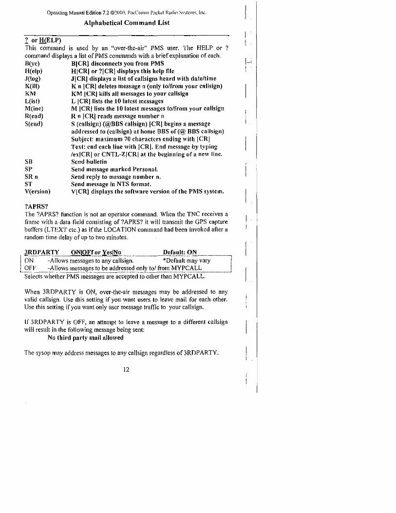
Operating Manual Edition 7.2 ©~O(Ji.i. P:1cCc)Jnl11 Jlackd Radii) \Y~(C1l1<;'. Inc.
Alphabetical Command List
1 or lliELP) This command is used by an "over-the-air" PMS user. The HELP or ? command displays a list of PMS commands with a brief explanation of each. B(ye) H(elp) J(log) K(iII) KM L(ist) M(ine) R(ead) S( elld)
SB SP SRn ST V(ersion)
?APRS?
B[CR} disconnects you from PMS H[CRI or ?[CRI displays this help file J[CRI displays a list of callsigns heard with date/time K n ICRI deletes message n (only to/from your callsign) KM [CRI kills all messages to your callsign L ICRliists the 10 latest messages M ICRIlists the 10 latest messages to/from your callsign R n ICRI reads message number n S (callsign) (@BBS callsign) [CRI begins a message addressed to (callsign) at home BBS of (@ BBS callsign) Subject: maximum 70 characters ending with [CRI Text: end each line with ICRI. End message by typing /exiCRI or CNTL-ZICRI at the beginning of a new line. Send bulletin Send message marked Personal. Send reply to message number n. Send message in NTS format. VICR} displays the software version of the PMS system.
The ?APRS? function is not an operator command. When the TNC receives a frame with a data field consisting of? APRS? it will transmit the GPS capture buffers (L TEXT etc.) as if the LOCA nON command had been invoked after a random time delay of up to two minutes .
• l~l).l'Al{1)'m.m ONIOFf_~~.r~Jli'? __ .. m .. _mmnn _____ ml) ... f~!I_I\:_9.N.nn _____ mnmnm, ! ON -Allows messages to any callsign. 'Default may vary ! i OFF -Allows messages to be addressed only to/ from MYPCALL i L ________________________________________ • __________ • ___________________________________________________________________________________ ~
Selects whether PMS messages are accepted to other than MYPCALL.
When 3RDPARTY is ON, over-the-air messages may be addressed to any valid callsign. Use this setting if you want users to leave mail for each other. Use this setting if you want only user message traffic to your callsign_
If 3RDPARTY is OFF, an attempt to leave a message to a different callsign will result in the following message being sent:
No third party mail allowed
The sysop may address messages to any cansign regardless of3RDPARTY.
12
1-

Operating Manual Edilion 7.2 ©2000_ Pw:Clllllln l'ad.,c( Radio Sysh:m~. [Ut
r.~IlJ[~Ql'IY ........ ~lQJ1r~~1:~sJJ:io ............................ I).~.f~~I.t:.9..N............ .... , ! ON -The high·order bit is not stripped in Converse Mode. ! l.g.I'F. ...... ::r.h.e .. h.i~~:()~~e.r.~it .. is.~tri.p.p.e~.i~.c,:()l1:'~r~~.t-10.de:.............................j
If 8BITCONV is OFF, the high·order bit (bit 7) of characters received from the terminal is removed before the characters are transmitted in a packet. The standard ASCII character set requires only 7 bits and the final bit is used as a parity bit or ignored.
If you need to transmit 8-bit data, but don't want all the features of Transparent Mode, you should set 8BITCONV ON and AWLEN 8 . This may be useful if you are using a special non· ASCII character set.
Bit 7 is always removed in Command Mode, because commands require only the standard 7-bit ASCIl character set.
,.A~Ig'!t!Q!t ...... .Ql'IlQJ1.r.~n:~sJl'I() ......................... .Il~r.~~.lt:.9..l'<.............. .... _ ! ON -Enables Prioritized Acknowledgments ! Lg.I'F. ....... :~ "i<Il()",I~~!lll1 "~ts~~v.".tll".s.all1.e.p.ri()ri.l!'.,,s.().th.e.r.lTa.l11es:................J
When ACKPRIOR is ON and the TNC receives a frame that it mllst acknowledge (ACK), it will immediately send the ACK if the channel is clear. Other stations with ACKPRIOR ON will defer accessing the channel for sufficient time to send the ACK, even if they cannot hear the station.
When ACKPRIOR is OFF, acknowledgments are queued up for transmission the same as any other frame.
ACKTIME n Default: 14 [;---·-~-O~-i-5-0-i~--io~-s;-~--i·~~-;;;~~~t;---------·----------------------------------- --------------~
,----------------------------------------------------------------------------_._------------------------------------------------------! ACKTlME specifies the time required to send an RR or RNR response frame (an acknowledgement) to an I frame at the radio port data rate. This corresponds to about 510mSec at 1200 bps with 8 digipeaters and abollt 140 mSec at 1200 bps with no digipeaters. The defallit of 140 mSec (ACKT 14) allows for no digipeaters. .
r . .!lliRJ).r:'!!' ........... ~I.QE~.~~1:~JJ:i~ ........................... .Il.er.~~I.t.9..N ...................... , ! ON - Address headers on monitored frames will be displayed. ! ! OFF - Address headers on monitored frames will not be displayed. ! ____________________________________________________________________________________ •• _ •• ________ ._. ________________________________ • ___ .1
ADRDISP enables or disables the display of the callsign addresses in each monitored frame. The command applies only to the terminal display, not printer output. Examples with ADRDlSP ON and OFF are shown below.
N4UQQ»N4UQR, TPA5* <VI R>:This is a monitored frame.
This is a monitored rrame.
IJ

Operating Manual Edition 7.2 ©200fl. P;lcComm P;lckd Raditl Syslc1H<;_lnc
,~QJIII}Lm... .ill!1 0 Ff.Q~.r~sJN Om..... ... mnmnm . .I>.e.r~ ~.lt:.2.JII ... mnm ....... n .. , ! ON - The month in all system dates will be alphabetic. ! L().~F ..... :.:r.he .. I11.o.l1t~.i~."II.sx.st~I11 .. d.at.e.s.\~ill .. b.e.l1.u.l11e.ri~:....................... ........ .J
This command selects alphabetic (Jan., Feb.,) or numeric (01,02) format for the month in date displays. AMONTH does not affect the PMS date format.
If AMONTH is ON: Apr.-15-00 19:48:01 15-Apr.-00 19:48:01
(DAY USA ON) (DA YUSA OFF)
If AMONTH is OFF: 04115/00 19:48:01 15104/00 19:48:01
;.;\.\J.I2.1'~Y.[)nm.n ONIOFr.~~.x~~JN.~nn ... n .... mmnnmnl).e.r~IJI.t:.2.Jllnnmm.mmmn, i ON - PMS messages are automatically marked for forwarding. 1
L().F~ ....... :~tI-I~.I11.e~s.a,\\.e~"r".I1~t.l11.a!~e.~.fo!.f0,:,v.a!~il1~: ...................................... .J This command enables automatic marking for forwarding of all messages with a caJlsign in the @ BBS field. This command does not cause forwarding to take place. To initiate forwarding, use the FPMS or FNPMS command or let the HOM EBBS to reverse forward.
,Mlr.().I;.J1.mmnmill!IOFf.Q~.x~JN.onn ... n ..... nm ....... P~.f~IJI.t:.2cJ11.mmm.mmmn, ! ON - A <LF> is sent to the terminal after each <CR>. ! i OFF - A <LF> is not sent to the terminal after each <CR>. i ~--------------------------------------.- --- .- ----------------------.--- -.-- --._------------------------.- .----.. -----------------------~
AUTOLF controls the appending of Line Feed characters to Carriage Return (CR) characters received in packets and the echo of those that are typed in. 1-This command only affects what is sent to the terminal, not the data sent in packets. To add Iinefeed characters to outgoing packets, use LFADD.
A WLEN n Default: 8
[.I1.~.2~~::ii;~:~~~~~~:~~~~i~:~i~~:E~~:~~~;~::::::::::::::::::::::::::::::::::::::::::::::::::::::::::::::::J To transmit and receive packets retaining all 8 data bits of each character, as you need to do if you send executable files or other special data, you should use Transparent Mode and set A WLEN 8. You can use Converse Mode and set A WLEN 8 and 8BITCONV ON, however the data you then send must handle the Converse Mode special characters with the PASS prefix.
,nh.)(.~~I;.2Y~.mnmill!IOFr.Q~.r~sJlio ........ m ..... nmnnm[).e.r~1J1.\:.2cJ11mmmnnmmm, ! ON - The packet controller uses AX,25 Level 2 Version 2.0 ! L()~~ ..... :.:r.I.le.p'a.cl<.et .. c()l1.tr()ller..u.s.e~.~~:~~.~.e.v.~.~.2.~e.'s.i()I1 .. I.:2 ........................ 1
Some implementations of the earlier version ofAX.25 protocol won't properly digipeat version 2.0 AX.25 packets. This command provides compatibility with these other packet controllers. Version I ofAX.25 (AX25L2V2 OFF) contains less overhead than Version 2 and is sometimes used in bandwidth limited situations. See also CHECK and CHEeKV!.
14

Operating Manual Edition 7.2 ©2i.lOO. PaCCllllUTI Pac!-.c:( f~adlo Sysl.:m:.. !m:.
AXDELA Y n Default: 0
[:.~.~.~.~:i:~9.;:~~:i~~:~~p.~:~t~~:~~X:~P::~~i~;:i~:io.:~~:i~~~~;~:~~~~:::::::::::::::.:: ... :::::::::·:.: AXDELA Y specifies the period of time the packet controller is to wait, in addition to the normal TXDELA Y, after keying the transmitter and before data is sent. This feature will be used when a standard "voice" repeater is used to extend range. This command works in conjunction with AXHANG.
AXHANG n Default: 0 r';:O~--2o:-~~i~~-~~p~~t~~--h-~~-g--ii~~-i~--ioo--~-;--i-~-~;~;~-~-i;--------------·--------·----·---·--·-·l
L--Tiirs--paramete~··can--be-·iise-d--io--increas~--th-e··cha~lneT-effic;ency··whe-n--volce-~ repeaters with a hang time greater than 100 ms are used. For a repeater with a long hang time, it is not necessary to wait for the repeater keyup deJay after keying the transmitter if the repeater is still transmitting. If the packet controller has heard a packet send within the hang period, it will not add the repeater keyup delay (AXDELA Y) to the keyup time.
BAUD NOTE: This command does not apply to all models. Some PacComm products use DIP switches or push-on jumpers for baud rate selection.
BAUD is an immediate command that displays the current terminal and radio baud rates and presents a selection menu. The initial portion of the BAUD display lists the current data rate of the terminal port and the radio port in use. The second portion of the display lists all supported radio and terminal baud rates and a command letter from each. A typical BAUD display:
Radio A -1200 B - 1200 C - 1200 D -1200
Select?
Radio: Port I: Port 2:
Baud Rates Port 1
L- 300 M- 1200 N - 2400 0-4800
P - 9600
1200 9600 4800
R- 300 S - 1200 T - 2400
x -Make changes arter restart
U - 4800
Z - Make changes immediately (li= ZAP)
Port2
V - 9600
Enter the letter X <CR> to return to the command prompt without making any changes to the existing data rates, or enter the letter which corresponds to the desired baud rate. The menu will reappear to allow correction or additional selections. When ready to accept the changes, enter X <CR> followed by the RESTART command or a power-off/power-on cycle of the TNC. This allows
15

time for changing the terminal baud rate before the packet controller changes. For baud rate changes to take place immediately, press the letter Z.
The BAUD command may be used at any time without changing the link state. The radio baud rate should NOT be changed if a connection exists. Only radio baud rates supported by the modem hardware should be selected. (some models only display the choices which the hardware supports.)
The data rates assigned to each letter may vary between products. Use the letters presented by the packet controller, not the table above.
BBSMSGS ONIOFf or Xesl~o Default: ON This command controls how the packet controller displays certain messages in Command and Converse Modes.
MESSAGE *** CONNECTED TO XXXXX *** DISCONNECTED *** retry limit exceeded *** XXX XXX Busy *** FRMR sent *** FRMR received *** Connect request: XXXXXX
EFFECT OF MMSMSGS ~ON Message appears on a new line Message appears on a new line Message appears on a new line Message appears on a new line Message appears on a new"line Message appears on a new line This message is omitted
The BBSMSGS command is useful for host operation with bulletin board software that requires link state messages to begin in the first display column.
, BF:~~«:>cN. .......... E.v.e.r>.'JY!~r..n ................................... p.e.r~lll.1:.«:>.1'1 ...................... , lEVER Y .. Beacon at regular intervals. i ! AFTER .. Beacon after specified interval with no activity. ! ! n ~ I .. 250, beacon timing in 10 second intervals (ifBRANGE ~ I) ! 1. ............ n.~.Q.c1.i.s~~I"s .. ~~a.c.o.n.s:.................. ........................................................ ..!
This command enables sending beacon and causes the first beacon frame to be transmitted. A beacon frame consists of the text of BTEXT in a packet addressed to the calisign in the TO field via the digipeat addresses specified by the UNPROTO command.
See also the BRANGE command which sets the beacon interval range.
BSLOT n Default: 60 ,.--------------------... ----------------------------------------------------------------------------------------------- .. ·---·"1 ! n ~ 0 .. 59 .. selects the second to be used for transmission of BTEXT when ! Lusi.n,\l ... t~e.Be~~~~ .. S}()ttil1.~.ftJ~c.ti()I1:.~.~"I.u~.~L~2.~i~~b.I:s .. th.e .. ftJl1~ti~I1: ............. ,j
This command is used in conjunction with BESLOT and BSUBSLOT to enable TDMA transmissions using BTEXT data. It allows an intelligent device to load data into the TNC for transmission in a precise time slot.
16
I,

Operaling Manual Edition 7.2 ©2i.100. PW:Cl)llHn Pachcl Ibdiu Sy,I':lllS. 111i.::.
This command assigns this controller a one second slot each minute for timeslotted beaconing when BESLOT is ON.
See BSUBSLOT for assigning multiple slots per second.
,.Ma.().'!u .... m .... ill!IOFf.~~.r~sJliomumuuu ...... umul).e.r~~I.t:.Q.r_� ... m ... mm.u' i ON - Selects TDMA beacon timing , i Lg_~~ ... _._._~_~~~~~!~_~_~~~~~!!~~~J_.~_~~~~!!_!_i_~_~~~:_ ...... ___________________________ . __ .. ________________ J
This command is used in conjunction with BSLOT and BSUBSLOT to enable time-slotted transmissions using BTEXT data. It allows an intelligent device to load a data string into the TNC for transmission in a precise time slot.
. .llli.Q!'IQJ;;leumm.~IOFr.~~.r~~Jli~muumumuuum.u.D..~.r~Il.It:.Q""m m.Uu .. mu_ i ON . <BACKSPACE><SPACE><BACKSPACE> is echoed when a ' ! character is deleted. I ! OFF - The <MS>BACKSLASH>(\) is echoed when a character is deleted. i l. ______________ . ___________________ . ____ . _______ • _________ •••• _ •••••• ____ ... ____ ._._._. __ ._. _______ .. ________ .. ___________ .. _. _________ .!
This command determines the way the display is updated to reflect a character deletion in Command or Converse Mode.
The <BACKSPACE><SPACE><BACKSPACE>sequence will properly update a video display. For a paper-output display, or if the terminal does not respond to the <BACKSPACE>character «CTRL-H», set BKONDEL OFF .
.. ~r_I.(;.J;:uuuu.uu!'uuuuu ... uu ...... uuu.uuu.uuuuuuuuuul).ef~lll.t:.:} .. uuu..uuuuuu i n = I Not supported. i 2 1 second i 3 10 seconds (default and traditional value) r 4 100 seconds L _________ .. ____ ••• _._ ....... __ .......... _ ••• ____________________________ •••• _ •• _ .. _______ .. ___________________________________________ _
This command sets the beacon timing multiplier by which the beacon timer increments. The BRANGE command allows beacons to be sent tram once per second to once per about each 7 hours.
With BRANGE = I (default value), the command BEl (beacon everyone) will transmit} beacon each ten seconds (1 x an increment of 10).
If BRAnge is set to 4, the BEl will trigger a beacon every 100 seconds (I x an increment of 100). (see LRANGE for Location beacon timing increments).
,.llli.J;:A~ONIOFr.~~.X~~Jli~ ... mmuumuuuu .. ul).~.r~IlJ.!:.9..r_ImuuuumUumm.mmm' i ON - The BREAK signal operates as described in the manual. i i OFF - The packet controller ignores the BREAK signal. i L ___ • __ ... ____________________ ... __________________ ...... _ •• __ .............. __________________ ........ _ .... ____________ ..... ____________ .!
The BREAK command controls enabling or disabling packet controller response to the BREAK signal. The BREAK signal is a 'space' condition on the
17

Operaling Manual Edition 7.2 ©20(JO. PacComlll P:J.ckd Radin S~'~ICIll'" In\:.
serial data input line for longer than two character times, which can be generated by many computers and terminals. Some devices will generate an inadvertent BREAK signal during initialization, which may force the packet I, controller into Command Mode. Setting BREAK to OFF el iminates this.
BSUBSLOT n Default: 0 ! n ~ 0-9 assig~~·;h~·;;~;;;b~;··';f·"iOO·;;;·S-;·~·b·;i~·i;·~~~d·;;;iih·b~~~';~·;·i.;ti;~g~-·······-··l L ...•.••••••••••••.•.••••••••••••••••••••.••••••.••••••••••..••.•.••.•••••••••.•.••••••••••••.•.••.••••••••••••••.•••••••.•••••••••.••• -'
This command is used in conjunction with BE SLOT and BSLOT to enable TDMA transmissions using BTEXT data. It allows an intelligent device to load a data string into the TNC for transmission in a precise time slot.
BSUBSLOT assigns the time offset in the assigned BSLOT second at which transmission begins. This allows multiple modems to be assigned the same BSLOT but transmit at staggered times to avoid collisions. A value of 0 causes the beacon to be sent at the beginning of the BSLOT second; a value of 5 causes the beacon to be sent 500 mS after the beginning of the BSLOT second.
If beacon transmissions do IIOt exceed 100 mS in length, for example, ten packet modems may be assigned the same BSLOT if each one uses a different BSUBSLOT, thus allowing ten timed beacons per second. If beacon transmissions are longer than 100 mS, between 100 and 200 mS, for example, five beacons per second may be accommodated by assigning BSUBSLOT values of 0,2,4,6, and 8. In the same fashion, three subslots of 300 mS each (and one of 400 mS) will be achieved using BSUBSLOT values of 0,3, and 6.
BTEXT text Defanlt: blank BTEXT specifies the content of the data portion of a beacon packet. The default text is blank, i.e., no message. Multiple-line messages may be put into the beacon by including carriage return <CR> characters as needed in the text preceded by the PASS character.
If a text string longer than 120 characters is entered, an error message will appear and the command will be ignored.
To clear the BTEXT text without using the RESET command, enter a new BTEXT with a % or & as the first character in the text.
NOTE: No beacons will be sent ifBTEXT is blank.
... l!QIl.I;I.§! ........... ONIOFr.~!.X~J!10 ............................ Il.~.fa.~I.t:.9.F.f ................... . i ON - Ignore frames from stations that are not in the LCALLS list. i L()~~_ ..... :.I.~n.o.r~.fl:a.ll1.e.s.fl:~!'1.s.t~~~'!s..t~~t.~r.e.1.ist,,~ .. i.n .. L.c::~L..L.~: __ ....................... J
BUDLIST specifies whether the cali signs in the LCALLS list are ignored (and thus not monitored, repeated, or allowed to connect) or, alternatively, are the only ones which are monitored, repeated, or allowed to connect.
18

Operating Manual Edition 7.2 ©20l)O. PacL(llnm Pache! R3dio Sysh.:m:-;. [IlC.
BUD LIST works in conjunction with the command LCALLS, which sets up a callsign list. These commands determine which packets will be displayed when MONITOR is ON.
BUDLIST and LCALLS also affect whether the listed call signs may connect or digipeat. (This aspect of these commands varies by model.)
.!!YE A command used by a PMS over-the-air user.
This command requests the PMS to disconnect the user by issuing a disconnect command. The user will see the following messages:
-Logged orr ***DISCONNECTED
There will be up to a 10 second delay after the "-Logged off' message is received before the PMS issues the disconnect request.
If a connection exists to the PMS and there is no radio port activity for approximately five minutes, the PMS will issue a disconnect command.
CALIBRA This command does not apply to all models. Refer to the Technical Reference manual for details about calibration procedures and the operation of this command.
CALI BRA is an immediate command used to transfer control to the modem tone generation routine. Ihe CALIBRA command may be performed at any time without altering the cUlTent link state. The command is useful for generating tones for adjusting radio transmit levels, etc, even on controller models which do not require its use for calibration.
The subcommands available in the calibration routine are: <SPACE> Switch the transmit audio to the other tone. K Toggle PIT line on/off D Alternately pulse both tones. Q Quit calibration routine .
.. CALSi!:.'l: ............. "-......................................................... .I>.eX~~.I\:.~2.~.i!: ............. '.'. i n ~ 0 - 65535 setting the count setting for the calibration routine. i ·Th·i·~··~~;;;;;;·a~d··do;;s···;;ot··~ppiy···io··~ii"·;;:;od;;is·.·"Th;;"·CALSET·c;;;;;;;;-a~'di~"
provided for continued support of the TNC·200 product. The functions of CALSET are not useful with any other PacComm INC.
19

Operating fvlanual Edition 7.2 ©:201'.!ll. P3c('Olnm P:lckd Radil1 Sy~tClll<;. Inc.
The nllmber to be specified by CALSET is detenmined by the frequency to be calibrated as follows:
modulator tones: demodulator tones:
n = (525,000 / f) + I n = (262,000 / f) + I
Round n to the nearest integer.
,£MiI:E"J;; ............ J1 .........•.....•..•..••.••.••..•..•••••................... )).e.r~~I.t:.~.1.8WI'l:r.Ic::l{L, L.n.::.Q.~.~Z~,.~e~c:iryin.¥ .. all.:~.~c:.II.~~~r~~t~r .. c.o.~e:................................ ............ j
This command sets the canceJ-line input editing command character. The parameter n is the ASCII code for the character you want to type in order to cancel an input line. Enter the code in either hex or decimaL For example, to change the cancel-line character to <CNTL-U>, set CAN $15 or CAN 2 L
I f you cancel an input line in Command Mode, the line will be tenminated with a <8ACKSLASH> ( \ ) and a new cmd: prompt. If you cancel a line in Converse Mode, YOIl will see only the< 8ACKSLASH> and a new line.
You may cancel only the line currently being typed. Once a <CR>has been entered, you cannot cancel an input line using the cancel-line character. If the send-packet character is not <CR>, the cancel-line character will cancel only the last line of a multi-line packet. To cancel the entire packet, use the CANPAC character.
Line cancellation is disabled in Transparent Mode .
•. ~~~ ...• _ ....... J1 .................•...•.. _ .••.•......................... )).e.r~~I.q!2J<;;I'I:r.Ic:XL, ! II = 0 - $7F, specifYing an ASCII character code. ! L ________________ + ______________ + ____ + ___ •• _. _ •••• ___ •••• _______________________ •• ___ ••• _._+ ••• _ •••••• __ ••• +. ___ ._. ___ •• __ ••••••• _____ • J
CANPAC is used to set the cancel-packet input editing command character. The parameter n is the ASCII code for the character YOll want to type in order to cancel an input packet. YOII can enter the code in either hex or decimal.
If you cancel a packet in Converse Mode, the line will be tenninated with a <8ACKSLASH> ( \) and a new line. You can only cancel the packet that is currently being entered. Once you have typed the send-packet character, or waited PACTlME [ifCPACTlME enabled], the packet can not be canceled.
Packet cancellation is disabled in Transparent Mode.
The cancel-packet character also cancels display output in Command Mode. If the cancel-packet character is typed while in Command Mode, any characters that would be sent to the screen (except echoed characters) are "thrown away." Typing the cancel-output character a second time restores output. To see this work, type DISPLAY, then a <CTRL-V>. The command list display will stop. You won't see any response from the packet controller to commands. Now type another <CTRL-Y>, and DISPLAY to see the nonnal display again.
20

Operating Manual Edition 7.2 ©20()O. Pa,;Ctll1Hn Pncher R:ldio Syst..:ms. Ill\,: .
.. CBE:11 ............... ONIOFf.~r..Xe.~JNo .......... m ............... J).e.f~1l1.t:.9.I?fm .. m .. m .. "". i ON - A bell character is sent with the connect message. i l .. Q.~~._ .. __ .. ~.~~.~~~~ __ ~h~~~_~.t.~~.~~ .. ~~~~~~~~_!~_~_~_~.~~~.~~~~.~_~~~.~~~~.......... ..j
The CBELL command controls whether an ASCII $07 (BELL) character is sent as part of the connected message. When CBELL is ON, the bell character immediately precedes the asterisk portion of the connected indication.
CBELL produces a 'CONNECT BELL' even if MFIL TER is set to delete $07 (BELL) characters. MFILTER only operates on the message body.
CHECK n Default: 30 f;;;-T~250:';;;~~'i'fYi~g';h'~'~h~~k'ii;;;'~"i'~'i'o';'~~~~d"i~i~;~~i~~""""""""""""'! ! A value of 0 disables this feature. i ••••••••••••••• __ •••••••••••••••••••••••••••••••••••••••••••••••••••••••••••••••••••••••••••••••••••••••••••••••••..•••••••••••••••••••• J
CHECK sets the connection timeout. When the packet controller is connected to another station, it will try to close the link if the specified CHECK time elapses without any packets being heard fTom the other controller.
IfAX25L2V2 is ON, the packet controller will send a "check packet" if no packets have been heard from the connected station for n*IO seconds .. If a response is not heard after RETRY+ I check attempts, it commences a disconnect sequence, as if the DISCONNECT command had been given.
IfAX25L2V2 is OFF, use the CHECKVI command.
,. CHECKVL ...... ~IOFf.~!:Xe.~Jrig .......................... J).e.r~1I!.t:.!).I'L .... m ........ , i ON - Enables CHECK time when running AX.25 Version l. i l.Cl.~~... ... :~e.'lllir~~.~.1l1~~1I~1.~i~c.()n.lle.c.t .. s~911~11~~:.......................................J
When ON, the CHECK (T3) timer is used to automatically disconnect an AX.25 Level 2 Version 1.0 link when data hasn't flowed for CHECK time. This will result in an automatic disconnect when packets haven't flowed between this TNC and the REMOTE TNC for CHECK time.
When OFF, V. 1.0 procedures require a manual disconnect of an inactive link.
CLKADJ ............. I1 ......................................................... P.~X~II!!:.!l ............. .. [:.n .. ::.2.~.~~~~~,.~~~c.~f?'i.n!i .. th.e.!~~I:ti.l11.e .. c.l.o.c.k..~p.~~~lIp..t:a.c~o.r: ..................... : .... :::j
This command allows the clock speed to be increased to compensate for the tendency to lose time when the radio port is very active. If the value of CLKADJ is non-zero, then the correction factor is calculated as:
relative clock speed in % ~ 100 + (9.16667 * lin).
NOTE: A small value ofn has a large effect on the clock speed, a large vallie ofn has a small effect. A value of"O" means no correction will be applied.
21

Operaling Manual Edition 7.2 ©~oon. P:lCCOrTIlll P;lCKct Radii) S~·s.(clJl~.lnc.
CLKSET Default: ON
ON - The controller will accept clock update ITom HOMEBBS. OFF - The controller ignores clock updates.
If CLKSET is ON and the HOMEBBS supports clock updating, the TNC date and time will be updated when the HOME BBS connects to the PMS.
CMDTIME n Default: 1 n = ° -250, Transparent Mode timeout value in seconds. This command sets the Transparent Mode timeout value.
Three Command Mode entry characters must be entered less than CMDTlME seconds apart, with no intervening characters, after a delay of CMDTIME seconds since the last characters were typed. After a final delay of CMDTlME seconds, the controller will enter Command Mode (cmd: prompt).
For example, using default values, a period of one second must elapse with no input, followed by three <CTRL-C> within one second, followed by an additional one second with no input.
If n is zero, the only exit ITom Transparent Mode is sending the BREAK signal.
CMSG Default: OFF ON OFF
- A text message is sent when a connection is established. - The text message is not sent.
CMSG ON enables automatic sending of the message contained in CTEXT whenever the packet controller accepts a connect request. No CMSG will be sent ifCTEXT is blank, even ifCMSG is ON.
CMSG is useful for an automatic human-readable greeting, and also for sending an initiation or connection acknowledgement string to the device attached to the controller initi~ting the connection.
See also CONRPT which sends a location report similar to CMSG.
CMSG2 Default: OFF ON - A text message is sent by calling TNC after connecting. OFF - The text message is not sent. CMSG2 ON enables automatic sending of the message contained in CTEXT whenever a cOllIlection is extablished which was initiated by the packet controller. No CMSG will be sent ifCTEXT is blank, even ifCMSG is ON.
22

Operating Manual Edition 7.2 ©2noo. PacCmnm Pac!-"r Radiu S:~h.'nb. Inc.
CMSG2 is useful for an automatic human-readable greeting, and also for sending an initiation or connection acknowledgement string to the device attached to the controller accepting the connection.
See also CONRPT which sends a location report similar to CMSG.
CMSGDISC ONIOFf or YeslNo Default: OFF
ON - The packet controller will disconnect immediately after receiving acknowledgement of the CTEXT sent by the CMSG command.
OFF - The controller will not disconnect after sending CMSG. CMSGDISC controls whether the controller will automatically disconnect after the CMSG packet containing the connect text (CTEXT) is acknowledged.
COMMAND n n ~ 0 - $7F, specifying an ASCII character code.
This command sets the Command Mode entry character. The code may be entered in either hexadecimal or decimal. Command Mode is entered from Converse Mode when this character is typed. If it is input while already in Command Mode, nothing happens.
See CMDTIME for infonnation on how the Command Mode entry character is used to escape from Transparent Mode.
CONMODE Default: Cony
Converse - Sets entry to Converse Mode when connection begins. Transparent - Sets entry to Transparent Mode when connection.begins. CON MODE selects which data transfer mode the packet controller will enter when a connection is established or when power is applied if U!t'"IODE (DATAMODE) is ON. The connecLion may result either from a radio connect request or a keyboard command. I f the connection is made from the kc) bonrd. the timing of the mode change is determined by NE\VMODE.
If the packet controller is already in Converse or Transparent Mode when the connection is completed, the mode will not be changed.
Ifpart ofa command line has been entered when the connection is completed, the mode change will not take place until the command is completed or the line is canceled to prevent the last part of the command from being sent as data.
CONNECT call# I - Callsign of packet controller to be connected to. call#2 - Optional callsign of station to act as digipeater.
CONNECT initiates a connect request to call# I, optionally through one or more digipeaters [VIA call#2[,call#3 ... ,call#9]. An error message is returned if
23

Operating Manual Edition 7.2 ©20()fi. P:1cCOJnm P:~ckc{ Radin S.V:-lCIl1$. Inc.
the controller is already in a connected state, or is attempting to connect or disconnect. If no response to the connect request occurs after RETRY attempts, the command is aborted and a failure message is displayed.
The double-bracketed text, "[call#3 ... ,call#9]," is only used if Via call#2 is present The brackets are not typed. Each callsign may include an optional sub-station ID (specified as "-n". The digipeater callsign fields are entered in Ihe order in which you want them to relay the packets to the destination, call# I, separated by spaces or commas.
If NEWMOOE is ON, the controller will immediately enter the data transfer mode specified by CONMOOE . If NEWMOOE is OFF, the controller will enter the data transfer mode when the connection is completed.
CONOK Default: OFF ON - Connect requests will be accepted. OFF - Connect requests will be rejected.
This command determines the action taken by the controller when it receives a connect request. IfCONOK is ON, the connection will be completed.
If CONOK is OFF the packet controller will issue a OM packet, or "busy signal" to the requesting station and display (except in Transparent Mode):
connect request: XXXXXX(calisign of station attempting to connect)
When a OM packet is received in response to a connect request, the packet controller will display:
*** XXXXXX station busy (callsign to which connect was attempted)
CONPERM ON OFF
Default: OFF The current stream's connection will be maintained. The current stream connects and disconnects nonnally.
CONPERM ON forces the packet controller to always maintain the current connection, even when RETRY attempts exceed the limit. RESTART and power cycling do not affect this connected state. If the connection is broken, connect requests will be sent indefinitely until the connection is re-established.
A connection must already exist for CONPERM to take effect. It functions on a stream-by-stream basis when multiple connections are enabled.
CONRPT Default: OFF ON - The GPS buffers' contents are sent when a connection is accepted. OFr - Capture buffers are not sent when a station connects to the TNe.
24

Operating Manual Edition 7.2 ©2flOO. PaCCllllln PadC"1 Radio S:--Sl\?nlS. 1111':.
If CONRPT is enabled, the GPS capture buffers; LTEXT, Ll TEXT, L2TEXT, and L3TEXT; STEXT (if it contains data); and CTEXT (if it contains data and CMSG is set to ON) will be transmitted whenever a connection is made.
CMSGDlSC controls whether the connection is maintained or broken.
CONSTAMP Default: OFF ON - Connect status messages are time stamped. OFF - Connect status messages are not time stamped.
CONSTAMP enables time stamping of*** CONNECTED status messages.
DAYTIME must be set for time stamping to occur. The date fomlat is set by the DA YUSA command. If CONSTAMP and DA YUSA are ON, and the date and time have been set, a connect message might appear as follows:
*** CONNECTED to KL7EV 105128/97 16:28:31J
CONVERSE or K K is a single letter alias for Converse.
CONVERSE is an immediate command which causes the packet controller to change ITom the Command Mode into the Converse Mode. The link connection is not affected. Once in the Converse Mode, everything entering the serial port is packetized and transmitted. Entering the Command Mode entry character returns the packet controller to the Command Mode.
CPACTIME Default: OFF ON - Packet timeout is used in Converse Mode. OFF - Packet timeout is not used in Converse Mode.
This command enables the periodic automatic sending of packets in Converse Mode. After CPACTIME has elapsed since the last ITame was transmitted, any characters which have been input to the terminal will be transmitted.
IfCPACTIME is ON, characters are packetized and transmitted periodically as they are in Transparent Mode, but local editing and display features of Converse Mode are enabled, and software control may be used. The SENDPAC character appearing in the text will also trigger transmission of a packet.
CPOLL n Default: blank
n ~ I to 4 ASCII characters specifying the CPOLL match string. Enter ITom 1 to 4 characters, followed by a <CR> into the CPOLL buffer. This is the match string to cause the remote TNC to send back it's L TEXT and Ll TEXT buffers. Please note it only sends back those two buffers.
25

Operating Manual Edition 7.2 ©~O(Jn. l'a..:l"olUm Pad:\!! Radil) S~>,IC11lS. Inc.
The string must be sent by the polling TNC as the first characters of an I frame sent to the polled TNC. The polled TNC will then respond with it's buffers, if they have anything in them.
You cannot use any of the special characters that do other things to the TNC, like the I which is the stream switch character, and of course you can not use the special characters that clear the text buffers.
CR ONIOFfor YeslNo Default: ON ON - The send-packet character, nonnally <CR>, is appended to all
packets sent in Converse Mode. OFF - The send-packet character is not appended to packets. When CR is ON, all packets sent in Converse Mode include the send-packet character which forces the packet to be sent. If CR is OFF, the send-packet character is interpreted only as a command, and is not included in the packet
CR ON and SENDPAC $OD gives a natural conversation mode. Each line is sent when <CR> is entered, and arrives with <CR> at the end of the line. [fthe station at the other end reports overprinting oflines on his display, set LFADD ON, or the other station can set AUTOLF ON.
CRAFTER Default: ON - A carriage return «CR» is sent to the tenninal afier each frame. - Monitored frames are displayed without adding a «CR».
CRAFTER OFF eliminates the <CR>character which is nonnally added to the end of each monitored frame. CRAFTER affects data on both the tenninal and printer ports.
If monitored frames overwrite themselves on the same line, set CRAFTER ON. [fmonitored frames are double-spaced, set CRAFTER OFF. CSTATUS CST A TUS is an immediate command which shows the stream identifier and link state of all streams (links), the current input and output streams, and whether or not each stream is "pennanent" (see CON PERM). For example: cmd:CS A stream- J/O Link state is: CONNECTED to :"oWADJ via K9NG B SCream- Link sCate is: CONNECTED to AD71-2 P C stream- Link state is: CO;'\'NECTED to G6DU D stream- Link state is: CONNECTED to K4ABT E stream- Link state is: DISCONNECTED
The example shows A stream is the currently active stream for both input and output, indicated by the I and 0 symbols. The B stream is connected to AD?I "pennanentiy." All other streams' states are shown as they might nonnally appear with multiple connections.
26
I-I

Operating Manual Edition 7.2 ©20nO_ Pw::CotmTI Pad.cl H:1dio Syst..:ms. Inc.
Note: The number of streams available varies among product models.
CTEXT text Default: blank text . Any combination of up to 120 characters and spaces. CTEXT specifies the text of the packet to be sent after a connection is made, if CMSG or CMSG2 is ON. The default text is blank, i.e. no message. Note that CTEXT is the buffer for both CMSG and CMSG2 functions.
Multiple-line messages may be sent by including carriage return «CR» characters in the text preceded by the PASS character. Entering a string longer than 120 characters gives an error message and the input is ignored. Enter CTEXT %<CR> or CTEXT &<CR> or use RESET to clear CTEXT. See also the CMSG, CMSG2, CMSGDlSC, and CONRPT commands.
CWID EvervlAfter Default: E-O EVERY· Send CWID at regular intervals. AFTER . Send CWID once if any packet activity during the interval. n = I - 250 specifYing 100 second intervals. Zero disables CWID. The CWID command enables CW identification (if CWIDTEXT is not blank) and sets the timing interval. Every/After works similarly to BEACON command except n is the number of 100 millisecond intervals.
CWIDTEXT text Default: blank
[~:."t ... ::::::::~r:i;;j:?::;X;;;:~~i;::~:~i;;:;~;:;;~ii~~~i:B~;~~:~~~~::::::::::::::::::::::::::::::": .. j CWIDTEXT may contain up to 32 characters of text to be sent as CWID. Accepts all alphabetic, numeric, and common punctuation characters. The length of CWID is limited by the packet controller PTT watchdog timer. At 20wpm, about 13 characters may be sent.
.£lY1.J;;I'/ .............. I1 ...................................................... J).e.r~'!I(!.(i........ ......... " l..n .. :.Lt.o.Ls!'.e~i12'.il1(?,.t~~.r.el.at.iv.eJen.~t~~fs:~I.I) .. d."ts:.............................. j
The CWID speed is set by specifYing the relative dot length. The default CWLEN setting of 6 yields approximately 20 wpm. A CWLEN of7 yields 10 wpm, and a CWLEN on yields 40 wpm.
,. DA T '\.~9..q ............ ............ .!lliIO Fr.~~.X~Jl1o ............. J).e.r~'!I.t!9..I'L ................. , i ON· Disregards all characters from serial port ifno connection exists. i i OFF· Accepts all characters from serial port regardless of connection status. i L ____ . _______ ... _________ . ____ .• ___ •.. _ .. ____ ._. ____________________ ._ .. ___ ........... ___________________ .. __ ._. _______________________ J
DA TALOG determines whether the packet modem accepts data from the RS· 232 serial port if there is no connection established. If the device attached to the serial port is a data logger Or other reporting device which continnously outputs data, it may be desirable to disregard any data from the device unless a
27

Operating f\'hmual Edition 7.2 ©2flOIl. P:1cComm P;l.:kd Radi~) \n,lcm<;.. Inc.
packet connection exists, since the data stream might be interpreted as commallds by the packet modem ..
Once DATALOG is set to ONi it can only be set to OFF by an over-the-air remote command or by removing the memol)' backup battery jumper to retum all parameters to factory settings.
f' ~~ ~ AMfI;;~~~t~;ii~;··i·I;·it~~~~~;;~~~~~E~"'····~·~.r~~l.t:.Q.!':!. ................... ! LgX~.: .... :rll~.~~l1t~()II"r .. in.iti~li~"s . .iI1.s:.?IllIl1~I1~.Il1()~~: ......................................... j
When DATAMODE is OFF, the packet controller initializes to the Command Mode and waits for a command from the asynchronous serial port.
When DATA MODE is ON, the packet controller initializes into the CONMODE without any commands from the serial port. Any characters received from the serial port will be packetized and transmitted as VI frames.
On some models/some fimlWare versions this command is named UIMODE.
,.My.1'IJ\:IJ;; ......... .Y)'y.yl1l.I1l.~<IIl.IlI~IIl ........................... .I>.e.r~~I.t: .. n.o.Il~ ................... . l.m')'n""~~~llll1'".~.s:.u.rr.el1.t .. d.a.te .. a.n.d .. till1,,t().~e.t: ................................................. i
This command sets the current date and time for the packet controller. If the command DAYTIME is entered without a parameter, lhe controller will display the current date and time setting.
yyyy are the four digits of the year, mm is the two·digit month code (01-12), dd is the day (1-31), hh is the hour (00-23), and mm is the minutes after the hour (00-59). All these codes except the year must be exactly two digits; numbers from 0 to 9 must be entered with leading zeros.
This command automatically supports the hardware clock if installed.
Related commands: UTC, FIXTYP .
.. .I>.t\'ylJ.~A .......... ONIOFf.~~.Xe.~Jli~ ........................... I?e.f~~I.t:.Q.l\' ...................... .. i ON .. Date displayed in the VS form as mm/ddlyy ! L.()~~ ...... :I:>~t".~is!'I~!'e.~.il1.tl",.!'llr())l.e"l1.fo.fl11."s .. ~~:1l1.Ill:!'!': .......................... !
This command affects the format of the date display used in "time stamps" as well as when the command DAYTIME is entered without parameters. The format for entering time using DAYTIME is not affected.
DEADTIME Discontinued Command The DEADTIME command is no longer supported in PacComm firmware. The command may be present in some firmware versions, but is not operative.
28
1-:

,_1lli1I'.I"nnmm ___ Q~.I0 Fr.~! y ~sJ!i~mm ___ m_m ______ nm.D._e.r~I!I_t:_Q.I'r,m __ m____m_, ! ON - The DELETE character editing key is <DELETE> ($7F) i LgX~ ________ :_:r_h_e __ [)_EO'='_EO!EO_,,~~r.~_ct~r._~_diti~~_~~ti_s_:<_El~<='~~I'i\~E:':J$_O_~L_____j
This command sets the editing command for character deletion_ When this character is typed, the last character from the input line is deleted_ How the controller indicates the deletion is controlled by the BKONDEL command_
DELETE will not delete past the beginning of a line, however <CR> characters that have been entered in the text with the pass character may be deleted_
To see a corrected display of the current line after you have deleted citaracters, type the redisplay-line character, which is set by the REDISPLA command_
,_llii!!.S_<;:AI;_L. ______________________ ~_a_\I[:~L ______________________________ I>.e_f~lll_t:J~I<::JV_I ____________ ,
! call - To-callsign of the frame to be treated as DGPS data_ i i n - 0-15, an optionally specified sub-station ID (SSID)_ 1 l _________________________________________________ ........ __ .. ___________________ ...... ___ ...... _. ______________ ... _____________________ _
DGPSCALL sets the to-call sign which the TNC uses to identify OGPS frames_
DIGIPEAT n Default: 7 r--O--------:-[jiCi"iPEA-Y-oi'-r-----------------------------------------------------------------i I _ DlGtPEAT ON and DlGI-SWAP enabled
2 - DlGtPEAT ON and DlGI-NOT-OWN enabled 3 - DlGtPEAT ON, DlGI-NOT-OWN and DlGI-SWAP enabled 4 - DlGIPEAT ON and DlGt-ONCE enabled 5 - DlGtPEAT ON, DlGt-SWAP and DlGt-ONCE enabled 6 - DlGtPEAT ON, DlGt-NOT-OWN and DlGt-ONCE enabled 7 - DlGtPEAT ON, DlGt-SWAP, DlGt-NOT-OWN, and DlGI-ONCE
, enabled (default) ! 8 - DlGtPEAT ON (the fomter D1GIPEAT ON without new features) c __________________________________________________ ._. ____________________________________ • ____________________ .. __________________ . ____ J
When DlGIPEA T is ON, i,e_ n ~ any non-zero value, every packet received with the packet controller's callsign (and SSID) or MY ALIAS callsign in the digipeat list of its address field will be retransmitted, subject to the restrictions of DlGt-NOT-OWN and DlGI-ONCE (below)_ Each station included in the digipeat list relays the packet in its tum_
Digipeating takes place concurrently with other operations and does not interfere with nonnal packet operation. If the packet transmitter is observed keying up without apparent reason, it is likely that it was digipeating a frame.
The HID command enables automatic ID for dedicated digipeaters_
DIGI-SWAP - This function causes the TNC to replace the alias (generic) callsign in a frame with MYCALL when the TNC digipeats the frame_ This
29

Operating Manual Edition 7.2 ©~(J(Jil. PacCormn Packd Radil1 s,n.lcm:::. In~.
allows subsequent stations to know the real path taken by the frame so that a reverse addressed frame may be sent back. It also places valid packet station identification in the frame.
DIGI-NOT-OWN - This function causes the TNC to never digipeat a frame that was originated with its own MYCALL. It prevents multiple repeating of the same frame due to multiple alias callsigns when DlGI-SWAP is off.
DIGI-ONCE - With OIGI-ONCE ON, it will not repeat the frame a second time regardless of which ali~s callsigns may match.
DISCONNECT DISCONNECT is an immediate command which initiates a disconnect from the currently connected station. A successful disconnect results in the display:
*** DISCONNECTED
Other commands may be entered while the disconnect is taking place, although connects are disallowed on that stream until the disconnect is completed. If the retry count is exceeded while waiting for the other side to acknowledge, the packet controller moves to the disconnected state. If a second DISCONNECT command is entered while the packet controller is disconnecting, the retry count is immediately set to the maximum number resulting in an immediate disconnected state.
III either case, the disconnect message is: *** retry count exceeded *** DISCONNECTED
Disconnect messages are not displayed when the packet controller is in Transparent Mode.
"lli§f~i\,X ........... .L~I~~s .. ':'.A!.IJ.LC::!.~,J!.~!.M,J\.!l ............................................ . Class is an optional parameter, class identifier, one of the following:
Async display asynchronous port parameters Bbs display PMS parameters Character display special characters CPS display GPS parameters Hea Ith & Hardware display health counters and LED status Id display ID characters Link display link parameters Monitor display monitor parameters Prin ter display monitor parameters
l .. !i.l11i~.~.......................... ... d.isp'.!a2'.til11i~~J'.ar.a.'.n.e.te.'~ .......................................... J 30
[ I

Operating Manual Edition 7.2 ©2(lOU. PacC\)lll1n Pad:('[ R:ldio S) sl~ms. Ill<:.
DISPLAY is an immediate command. When entered with no class parameter will cause all control parameters and their current values to be displayed.
Sub-groups of related parameters can be displayed by specifying the optional parameter-class e.g. DISP T for the Timing Parameters. All individual parameters can be displayed by entering the parameter name with no options, e.g. AXD will display the value for AXDELA Y.
The DISPLAY format is set by the FSCREEN command .
. Jill~t\.II........ ... II .......................................................... J).e.r~lllt:-'L.......... ........ . L.11.~.Q.~..2.5.~,.s.p'e.c.if)'i~~.~.e~a.u.lt.\Vait.til1l~.i.n .. I.o .. I1l~Jnter~~ls...................J
This value is used to avoid collisions with digipeated packets. The packet controller will wait the default time after last hearing data on the channel before it begins its keyup sequence, unless it is waiting to transmit digipeated packets.
[f all stations specify a proper wait time the digipeater will capture the frequency every time it has data to send, because digipeated packets are sent without delay.
;.E.!llit\.c::<:>I'/ ......... ill!IOFf.Q~.r~sJJ:io ........................... J).e.r~~[J:<:>l'f .................. , i ON - BTEXT echoed on terminal port when it is sent to RF port ! L.()~~ ....... :.~:r.IO;.(:r:is.n.o.t.e.cll.o.e.d .. ()I1.t~~.t~l1llinaLp.()rt.........................J
This command allows monitoring one's own transmitted beacons by echoing the data in BTEXT to the terminal serial port when a beacon is sent out the radio port. This monitoring is useful as a reminder of what is being sent to reduce the possibility of sending stale (forgotten) beacon messages .
. E..c:.lI.Q ................ ill!IOFr.Q~.r~sJJ:io ........................... J).e.r~~I.t:.<:>l'I ................... , i ON - The packet controller echoes characters from the terminal. i ! OFF - Characters are not echoed. ! c •• _____ •• ___ • __ •••• _____ •• _____ •• ________________________ •• __ • __ • _________________________ ._._. ________ '- ___ ____________________________ J
This command controls ECHOing to the attached terminal by the packet controller when it is in Command or Converse Mode. (ECHOing is disabled in Transparent Mode).
If you don't see what you type, you should set ECHO ON. If you see two copies of everything, you should set ECHO OFF .
. JillIr.!:I:!:l~ ........... !I.!.~.:~a.1l,Jffi.:.~.~.1.U!'J ................................................................. " i n - message number to be edited. ! ! to-callsign - revised call sign to be placed in 'TO:' location. ! i @·callsign - revised callsign to be placed in '@ BBS:' location. ! ! [nl - optional ssm. ! c ___ •• _. ______ •••• ______ • _________________________ •••••• ______________________ ._. __ ._. __________________ • _______________________________ J
31

Operating Manual Edition 7.2 ©20(JO. P::IcCoJnm P3ckl!l Radio .)v:;tcm5-. Inc
The ED/THDR command edits PMS message headers to allow re-addressing of messages (changing the TO: callsign) and revising the calisign in the '@ BBS' field. It does not allow editing the BID.
The ED/THDR command needs the message number and either or both callsigns. If parameters are incorrect, the following will be displayed:
Parameters are missing
To revise only the 'TO:' callsign of message 9, enter the following: ell/d: EDITHDR 9 W4MUA <CR>
The PMS will respond with the following display: Msg # Stat Date Time To From @ BBS
Subject 9 T 07/15/94 09:54 WIAW WS4Z @ W4DPH VE tests
New IIIessage header Msg # Stat Date
Subject 9 T 07/15/94
Time To From @BBS
09:54 W4MUA WS4Z @ W4DPH VE tests
Similarly, to revise only the '@ BBS:' callsign of message 9, enter: ell/d: EDITHDR 9 @KOZXF <CR>
To revise both caIlsigns in message 9, enter the following: ell/d: EDITH DR 9 N4UQR KOZXF <CR>
To remove the callsign in the '@ BBS' field in message 9 and leave the field blank, enter the following:
ell/d:EDITHDR 9@<CR>
Note: The 'before' and 'after' displays have been omitted.
ELOC n Default: 0 [·O:-;if·························· ....... _ ........................................... -.. ·············_···_·_·······_·············1
j I ~ sends content oflocation beacons to tenninal port only i L2.oo_~e.n.d.s .. c()l1_te.~_t_()~I.o.c"ti.o.n .. ~e.a.~()I1.s.t() . .t.e':l"i~"I.,,~~.~.Jl.o.rt .. __ .......... _ ............. -..l
ELOC enables or disables echoing the contents of the LOCation beacons to the serial port. This allows monitoring of one's own location beacons.
ELOC allows monitoring one's own transmitted location beacons by echoing the data sent over the radio port to the tenninal serial port. This monitoring is useful with mapping programs to allow reception of one's own location report in the same format as those received over the air.
32

Operating Manual Edition 7.2 ©2ntlO. PilcC.l~lllm Pacl\cl Radju S~:;h:m:>. Inc.
;_~~XKr.n __ ONlillJ~~1:~~Jlio __ n ___ nuuunnu_n~~X~1I1_t:_9_l'fununnnun, i ON - Encrypts data by XORing text in KEY parameter. i l.g_F.~ _________ :_~(lI1~_s_~~t~_:i_n_th.e..c_le_a~: __________________ ._._ .. ______________________ ._. ___________________ J
This command causes the text for the information portion of the packet to be XORed with the text that is given in the KEY parameter. The bits will also be shifted by the number in the ENSHIFT parameter. Both sender and receiver need to have the same KEY and ENSHIFT values for information to be decoded properly_
• ENSHIFT n Default: 2
Ln __ ~_2:?:;:~~~:ryei!9~:b.;i:~b.;~:~~i:~~;::::::::::::::::::::::::::::::::::::::::::::::::::::::::::::::---:::::_:_J This parameter defines the number of bits to shift before the exclusive OR (XOR) process used for encryption. Both sender and receiver need to have the same KEY and EN SHIFT values for information to be decoded properly_
The typical use of this parameter is to allow short term changes in the excryption pattern by changing this single digit and leaving the 80 character key untouched. For example, the same KEY may be used by eight different operators by setting ENSHIFT.
__ E.§.C;:;\_l'~nnunu_~IOFf_~~_r~sJli~ __ nnuuu_.nnn ____ ~_eX~lIl_t:_9.I'Lnunnnu __ l ON - The <ESCAPE> character ($1 B) is output as "$" ($24). I ! OFF - The <ESCAPE> ($1 B) character is output as ($1 B). i L __________________ ••• __________________ • _______________________________ • ___________________________________ • ___________________________ .1
This command specifies the character which will be output when an <ESCAPE> character is sent to the terminal. The <ESCAPE> translation is disabled in Transparent Mode.
Some terminals interpret the <ESCAPE> character as a special command prefix. If you have such a terminal, protect yourself for unexpected text sequences by setting ESCAPE ON_ See also MFILTER.
r_E!~l\!g~gnunn 0 NI 0 Ff_~!1:~sJ N 0unn_. n_._ n . __ nuuP_e.r~lIl_t :_9_I\'_un .. -nun -u-, ; ON - F1RMRNR is active. ; I : ; OFF - FIRMRNR is disabled. i L _____ ._. ___________ • _____________________ ._. ___ • ________________________________________________________________________________________ ,
This command is used to prevent the frequent polling of remote TNCs when they are busy. The command works around the AX.2S Version 2 protocol specification for busy-poll timing, effectively eliminating excessive control frames being sent to a packet controller which has indicated it can accept no more data at the cUlTent time.
This command operates properly with remote TNCs having FIRMRNR set to ON and with most network nodes.
FIXTYPE n Default: 1
33

()pCr,lling \-Imlltal Edition 7.::! ,~::!O(KI. Pa~Corntll P:ld:~t RadiI) S:":.lcm~.ln~.
l:;;:~:2:~:5:::i~~~:~~;~:il~~:~~~:~~iEii~~~:~~i~~~?::::::_:::::::::::::::::::::::::::::::::::::::::::::::::::::::] NOTE I: This command is not implemented on all models_ NOTE2: The labeling of the FIX LED may vary among products.
This command establishes how the packet controller determines if a good fix has been obtained by the GPS receiver for control of the packet controller's FIX LED. Some options also let the FIX LED be triggered by non-GPS data if desired.
o ~ disable the function, i.e. do not check for a good fix and do not control the FIX/AUX LED.
I ~ Use the $GPGGA string to verity a good fix. (note that $GPGGA has to be specified as one of the TNC GPS capture fields (GPSTExt, LG Itext, LG2text, LG3text), but it can be anyone of the fOllr fields).
2 ~ If any string specified in any of the TNC GPS capture fields (GPSTExt, LG Itext, LG2text, LG3text) has a length of greater than 34, this will identity a good fix. (Since most GPS receivers don't put out any sentences or put out shortened ones when there is no fix, this option may allow effective fix detemlination based on sentence length).
3 ~ If any string specified in any of the GPS captllre fields (GPSTExt, LG I text. LG2text, LG3text) is exactly matched by a received string, this will identify a good fix. This is like option 2, but there is no minimum string length. For example if LG3text is set to $GPGSV and the GPS puts out $GPGSY:,x,O there will be a match.
4 ~ Use only LTEXT field to search for a string >34 characters for a good fix. This option uses only the data in LTEXT Cas specified by GPSTExt search) and ignores the LG 112/3TEXT fields. This lets the data collected in LG 1/2/3TEXT to be from something such as a weather station without affecting the good fix LED.
5 ~ Use the $GPRMC string to verifY a good fix. (note that $GPRMC has to be specified as one of the TNC GPS capture fields (GPSTExt, LG I text, LG2text, LG3text), but it can be anyone of the four fields).
,_.E.r,Q~n _____ n_n ____ ONIOFf_Q!.Y~Jlio_nn_. _______ n ______ nnl)_e.rlllll_t:_g-"; _______________ nn ___ , i ON _ Type-in flow control is active. i l. ()~ ~__ _ ___ :_:r2'[le_:i~_tl_()":_c_()l1tr()I_.i s .. dis~ ~I,,~: ____________________ ._ . ___ .__ .. __ ._________._ ... j
Setting FLOW ON will keep received data from interfering with data entry.
When FLOW is ON, any character entered from the tenninal will halt output
34

Operating Manual Edition 7.2 ©2ilOtJ. PatCllmm i-'ad,c, I~adi{) Sy-:l<.'f11~. !n;,.
to the terminal until: I) a packet is forced (in Converse Mode); 2) a line is completed (in Command Mode); 3) the packet length is exceeded; or, 4) the terminal output buffer fills up, Canceling the CUlTent command, packet, or typing the re-display character will also cause the output to resume. Type-in flow control is not used in Transparent Mode.
FORWARD
[~~~~~~~~~E~~~~~~~~~~!i(~~~~~~~~~~~~~~~~~~~~~~~~~~~~!?~~~!~~~~~~~!~~_~~~~~~~~~~~~~~~~~~~~~ __ . ___ . _____ .j This command allows messages to be marked for forwarding to another BBS station, Automatic forwarding is not supported to reduce channel congestion.
The PacComm PMS (Personal Message System) supports message forwarding (see FPMS, FNPMS, RFPMS, and RFNPMS commands) and automatic reverse forwarding. If you have an arrangement with your local BBS Sysop to forward BBS mail to your PMS, then the PMS will forward marked messages to the local BBS when the BBS connects to deliver your mail.
If you type: cmd: FORWARD n <CR>
The PMS will respond with: Message marked for forwarding
If you try to mark a bulletin for forwarding, the PMS will display: You cannot forward a bulletin
The FORWARD command also is used to remove the forwarding flag from a marked message. To undo the forwarding ofa message, enter:
c/IId: FORWARD n<CR>
The PMS will respond with the message: Message forwarding reset
,_J'l'i_I'M§ ________________ c_a_IIIiJ_JYi .. _~ .. II_Ii~L________________________ __ . ____________ _ j call # I - Callsign of node or switch to be connected to. , ! call #2 - Optional callsign of station to be digipeated through_ ! c. ____ ._._. ______ . ________ .. _________ . ______ . _______ . _______ . ___ .. _____ ._ ..... __ ... ______ ._. _____ ... _._ ... ___ . ________ ....... ___ ... __ .. _~
The purpose of this command is to forward marked messages to another PMS station via a network connection.
The FNPMS command causes the PMS to connect to a node or switch (call #1) via no more then one digipeater (call #2). Once this connection exists, the PMS sends the node the connect string contained in NODETEXT to cause the node to connect to the desired BBSIPMS station_ When that connection is established, the PMS uploads all messages marked for forwarding_
35

Operating Manual Edition 7.2 ©~(}(JO, PaCCOlTIlll [lackd Radin Syslcms..lnc.
If the station connected to by the NODETEXT is the HOMEBBS, the standard BBS forwarding fonnat will be used for transferring messages, otherwise the PMS will follow the standard "human" format.
I f the FNPMS command is used to connect to a station which is not a node, the NODETEXT will be sent but will be interpreted as data and no further action will take place. After approximately five minutes, the PMS will time·out and disconnect.
If the station connected to by the NODETEXT command string is not a BBS, capable of receiving PMS messages, or if a forwarding error occurs, automatic disconnection takes place .
. E!:M~ ................. .c.~.II.II!.lYi.lI.~lIll.II~L. ............................................................... , [ call #1 . Callsign ofBBS/PMS station to be connected to. [ i call #2 . Optional callsign of station to be digipeated through. i l .............. _._ •...........••...••........... __ ..••••....••...... _._._ .. _ ... _ ..•••....... _ .. _._ .... _. _____ ... _ ...••• ___ ••• __ . ___ .• _ .• J
This command causes the PMS to connect to a BBS/PMS station (call #1) via no more than one digipeater (call #2). The callsign string may not exceed 23 characters. Once this connection exists, the PMS uploads all messages marked for fonvarding,
This command may be used to upload messages to another PMS or human operator as well as a conventional BBS. If the station connected to by the FPMS command is the HOMEBBS, the standard BBS forwarding format will be used for transferring messages, otherwise the PMS will follow the "human" format.
If the FPMS command is used to connect to a station which is not a BBS or PMS capable of receiving PMS messages, or if a forwarding protocol error occurs, automatic disconnection occurs .
.. EBAq,<: ............... !l ........................................... I>.e.rll'!l.t:}.l~I!:§L ........................ .. l .. ~._~ .. ~.: .. !.~~_f~~_JE..~.~.~~!!_?':~.I.~_~.~~.'!l.~_~.~.~!~~~~~ . .i_~._~:~~~~~:._ ........... _ .. __ .... __ . _____ . __ . _____ ._J
After transmitting a packet requiring acknowledgement, the packet controller waits the frame acknowledgement timeout before incrementing the retry counter and sending the frame again.
If the packet address includes digipeaters, the Retry interval is adjusted to n * (2*m + I) where m is the number of relay stations.
" FSCI{.E.I<:~ .......... ONIOFf.~!.x~llio ........................... J).e.rll'!.I.t:.Q.l'I ...................... , i ON . The DISPLAY command generates four columns. i
l .. ()X~ ....... :.:r~le .. I).I~I'.~~X.~~I11l11~I1~ .. g.e.n"~a.te.s.~I1,,.~~1lJl11.n.: ......................... .J
36

Operating Manual Edition 7.2 ©.2f){)(L PW::Cl111lITI Packc[ n:JdlO Syst.:ms. 11li.:.
When FSCREEN is set to ON, the command displays will list the present settings of commands in four columns across the screen. All text type of commands will start in column I to ensure the full text is displayed. This command expects an 80 column display.
When FSCREEN is OFF, all status information will be presented in a single long column.
,. FUr,"'I~V!,"'!'.~.~IOFf.~~.y~sJlio ............................ J).e.ra.!!I.t:.QEE .................... . i ON - Full duplex mode is enabled. i i OFF - Full duplex mode is disabled. i L __________________ . ___ ... __ . ____ .... ____ . ___ ........ _ .... _. __ ._ .... _ •..•.... _._ .. _ .. ___ . ___________ . ____ . _________ ._ .. ___ ._. ___ . __ ....•
When full duplex mode CFULLDUP) is OFF, the packet controller makes use of the Data Carrier Detect signal ITom the modem to avoid collisions by on Iy transmitting when the channel is clear. Multiple packets are acknowledged in a single transmission. When FULLDUP is ON, the packet controller ignores DCD and transmits immediately whenever data or acknowledgements are packetized even if other ITames are being received. Packets are acknowledged individually.
FULLDUP should only be used if both communicating stations are full-duplex stations.
,.~ ...... ~l~.x.it.~~lI.r.a.c!~.r ........................................... .Il.e.ra.!!I.~:.Q.F:f. .................. , i ON - The Asynchronous port is configured for GPS data. ! l.,()X~ ....... :.:r:"e.t\.s!'I1~~on.olls.p.0.rt.i.s.~{)I1~.~lIr:~.~o~.~.t:fJ11.i.n.a.I.................J
The GPS command configures the packet controller to interface with a NMEA-0813 compatible Global Positioning System CGPS) receiver. When in GPS mode, all normal TNC commands are inoperative.
This command enables the GPS parser on the primary serial port. On dual serial port models, the GPS parser is enabled on the primary pprt and remains operative on the secondary port. Normal operatioll jor a two-port model witll a termillol 011 Port J alld a GPS receiver 011 Port] would calif or GPS OFF.
NOTE: To escape from GPS mode, the GPSEXIT character (default is backslash "I") must be sent over the serial input port. When in GPS mode, the packet controller may act "dead" to normal keyboard commands.
GPSEXIT n Default: I
[~:~:~:~:~!~;:~e~~i~;~i:~~:::\:~~:ii:~~~~~~i~~:~:~:~~:.::::::::::::::::::::::::::::::::::::::.:::::'::::::::J This command sets the value of the character recognized as the GPS exit character. There is no GPS OFF command. Once the GPS mode is ON, the GPSEXIT character must be used to get out ofGPS mode.
37

Operating Manual Edition 7.2 ©20r)f1, PacComlll Packd Radi\1 S~>.IC11l.~. Inc.
The default value "\" was selected since this character does not appear in any
~07n~~ ~~;I ~~:e~~:~; ~~r~:;,E~;~ ~o~~ ~il~ ~:I~:i~~i~~i~~~~t~~~:~~ i:I:~~ I : that character appears, '
r- ~:tSIIJ;;!Jp-i~-4-~~~-~-;~~-t~-;~-~r-;;-~~~i-t~-th~-~;;~~h~-d-~1i:~tt~~~----------------1 r-i immediately after the packet controller is powered on. i c _________________ • __________ • __ •• _____________________ •••• ___ • _______________ ••• ___ •• _. ______________________________ ••••• _______ • ____ J
This command sets the setup string to be sent via the asynchronous port to the attached G PS or other device. There are no constraints on the content of the field except that the length may not exceed 40 characters. The GPSITEXT is only sent ifGPS is ON and the GPSITEXT is not blank.
To clear the GPSITEXT without using the RESET command, enter a new GPSITEXT with a "%" or "&" as the first character in the text.
GPSLlMIT n Defaul!: 0 f"1I = 0-255 Maxjmum·~~~~~-b-~;-~f~~-~-~-~d~-G-PS-;~~~i~~~-~~·i-ii·~-~~~~i~~--~-l~--if~~--fi~:--l L ______________________________________________________________________________________________________________________________________ ~
GPSLlMIT sets the time limit ill seconds that the GPS receiver's power will remain on in the event that a good fix has not been received. This prevents excessive power consumption in instances where the GPS antenna is blocked from receiving adequate satellite signals to obtain a fix.
When the number of seconds specified by GPSLlMIT has been reached, the GPS receiver will be turned off just as if a good fix had been received. Wake up time is set by the GPSSLEEP command.
A value of zero (0) disables this command. If disabled, the power to the GPS receiver will stay on indefinitely until a good fix is received if GPSSLEEP is allowing the GPS receiver to be active.
GPSSLEEP n Default: 0
[n __ ~_~:_2_5_5 ____ ;~~~~:f:;.~;:i~~:~~~~-~~~~I:~~~vi:li_r:~~i~:~~:~~~:d::~~_a:~:r-~:_-J The GPSSLEEP command sets the duration in seconds that the GPS will remain off after receiving a good fix. A value of zero (0) disables this function, thus keeping the GPS receiver constantly powered.
When power conservation is required in a GPS equipped packet controller, the GPSSLEEP and GPSLlMIT commands, used properly, can reduce power consumption by over 90%. GPSSLEEP specifies the time interval between attempts to get a GPS fix. Since GPSSLEEP specifies the off time for the GPS receiver, the actual interval between fixes will be the sum of the GPSSLEEP
38

Operating Manual Edition 7.2 ©2iWO. Pm:Clllllrn Pat"-c! (~:1djo S)SknlS. Inc
setting and the time required for the GPS receiver to obtain a fix after a warm start.
GPSTE}(I ........... !~~L .................................................. .I>.e.c"II!.!:J'-Q.1'9.Q.J\. ....... _. text - Any NMEA-OI 83 string identifier supported by attached GPS or :
I .................. I:<?~P.-~!.e~~i,,~r: .. !~~.~o.fI11~t.is..~Si~~~)(.,,~.~I::<.x.x.x:... ................. j This command sets the desired search pattern to be loaded into L TEXT. Conventional usage would be the $Gxxxx or $Lxxxx identifier corresponding to a valid GPS or LORAN output sentence, however this field may be set to any value desired (to a maximum of9 characters).
For example, the value of "ERROR," entered into the GPSTEXT would cause the parser to search for the value "ERROR," (including the comma) and put the text ERROR, plus the following 120 characters into LTEXT.
To clear the GPSTEXT without using the RESET command, enter a new GPSTEXT with a "%" or "&" as the first character in the text.
GPSTYPE n Default: 1
Ll1.~.~.~.8::i~~~:~~~~ii~~:d.~~~~;~ii~~~:~~i~;~i::::::::::::::::::::::::::::::::::::::::::::::::::::::::j This command selects the type of GPS sentence or formatted string that is scanned for. String length is restricted to 70 characters. Consult the GPS/LORAN receiver documentation to detelmine which format is appropriate.
0= This is an invalid setting, and will effectively disable the GPS mode and return the TNC back to normal command mode ifGPS is turned on.
I = This checks for the string type that has been entered into the GPSTEXT buffer. All characters are sent.
2 = This mode parses the $GPGGA string in a special format. 3 = This mode parses the $GPRMC string in a special format. 4 = This is the #L format. (No parsing done on this string) 5 = This is the 'FF' 'FF' '01' format. (No parsing done on this string) 6 = This is the STX ETX format. (No parsing done on this string) 7 = This is the # format. (No parsing done on this string) 8 = This mode parses the $GPRMC string FIELDS 1-9.
i~~gQ-{j:rG~~~.p.~o~\~~~:~~r:~;~~d:.mnnnmnmm .. .I>.~.c,,1I1.t:_Q.F.fmmnnnmnl , : L()X~ ....... :.Sir.o.u.p .. l11o.~it,,~i~~.is..~is.ab.I~~: ....... nn .......................... _ ....................... j The GROUP command enables monitoring of information transmitted for s selected group of stations. The value of MASTERM is used to determine the group and subgroup identifications which are monitored.
39

Operating Manual Edition 7_2 ©2000. P.1cl"OlTIm P;Jckd RadiI) .)~·.slcm5_ lnc.
,HEi\P.I'.~Mmmill!IOFf.()~J:~sJ.!1omnnnnnnnmnnnnJ).eJ~~I.t:.9.I'fmm .. __ .nmm, iON - Address information for each line is displayed on the same line. OFF i lnnnnnnn.:.~~~~e.s~.il1f°':'11a.ti~!1.r.0.r.~~<:~.li~~.i~.~is.p'1ax~.d .. ~I1.i!~.()~.li!1.e:.nnnnnnj This command affects the display format. If HEAOERLI is OFF, the address infomlation is displayed with the packet: b.',
KV7D>N2WX:Go ahead and transfer the file. I •
If HEAOERLI is ON, the address information is displayed, followed by the packet text on a separate line:
N2WX>KV7D: Sorry, I'm not quite ready yet.
,HEAL~~~nnnn.ill!IOFf.()r..X~~JN~.nn .. n.nnnn.mnnnJ).e.r~1J1.t:.9.l'fm.m.m.m.m, iON - The controller will "dither" the CON and STA LEOs. i !OFF - The CON and STA LEOs operate normally. [ _______________________ • ___ •• _________________________________________________________________ • _________ • _____________________________ J
This command redefines the functions of the two CPU controllable LEOs (STAtus and CONnect) to indicate CPU activity.
When HEALLEO is set to ON, the two LEOs flash in alternate fashion indicating the firmware is executing and is not hung, When HEALLEO is set to OFF, the LEOs function normally, indicating a connection and any unacknowledged frames.
lliELP) or 1 This command is used by an "over-the-air" PMS user. The HELP or ? command displays a list of PMS commands with a brief explanation of each.
B(ye) H(elp) J(log) K(iII) KM L(ist) M(ine) R(ead) S(end)
SB SP SR n ST V(ersion)
BICR} disconnects you from PMS HICRI or ?ICRI displays this help liIe JICRI displays a list of callsigns heard with date/time K n ICRI deletes message n (only to/from your callsign) KM ICRI kills all messages to your callsign L ICRllists the 10 latest messages M [CRllists the 10 latest messages to/from your calisign R n [CR] reads message number n S (callsign) (@BBS callsign) [CR] begins a message addressed to (calisign) at home BBS of(@BBScallsign) Subject: maximum 70 characters ending with ICRI Text: end each line with ICRI. End message by typing /exlCRI or CNTL-Z[CRI at the beginning of a new line. Send bulletin Send message marked Personal. Send reply to message number n. Send message in NTS format. VICRI displays the software version of the PMS system.
40
[I

HELP A help facility for the operator of the packet controller. The infomJation provided varies from model to model. If the HELP function is not available, one of the following messages is displayed: ? unknown command or not implemented
This command is used to enable or disable the sending of identification packets by the packet controller. If HID if OFF, the packet controller will never send an identification packet. If HID is ON, the packet controller will send an identification packet every 9.5 minutes if the station is digipeating packets. The TO command allows the operator to send a manual identification packet.
Identification consists of an unnumbered I (UI) frame whose data field is the station identification (the callsign as set by MYCALL) with "/R" appended. The identification packet is sent to the address in the UNPROTO conunand.
The QRA function is similar. If HID is on and a UI frame is received addressed to QRA-O, the TNC will respond after a random time of up to two minutes with an ID frame. If HID is off (default), QRA will never send an ID.
r.l!QM.~IJ.IJ.~ ......... c.a.I!si.&!!.~.!! ........................................ .!l.e.r~!,I.t:.Il'()!!~""'''''''''''l i callsign - Up to six alphanumeric characters. i L. .......... ~ ... :.~!'ti.o.n.a.I.~~.IlJ..r.:0lll.Q.t~.-'-5: ................................................................... J
This command set the callsign of the "home BBS" which forwards mail to your PMS or which you normally access manually.
10 ID is an immediate command which sends a special identification packet. ID can be used to force a final identification packet to be sent as a digipeater station is being taken off the air. The identification packet will be sent only if the digipeater has transmitted since the last automatic identification. See HID for ID frame information .
• INPUT Po Default: blank !·p;;-::Th~·h~~;d~~i;;;;i·~~;;;b~~·~iih~·p~~~·ii~i·io·p;;rt·i~·b·~·~~~·;i.-· ...... · .. ···· .......... ·l L __ • _______ ._ •••• _____ ._. _______ ._ •• __________________ ._._._. __________________ ••••••• _. _________________ • ______________ • ___________ • ___ -'
This command reads the hexadecimal value of port n on packet modems equipped with parallel inputJoutput ports. This command may be entered by the local keyboard Of via an over the air remote command.
41

Operaling Manual Edition 7.2 ©'200fJ. PacCormll 1'3~kd Radio Syslem ..... Inc.
oINTERV AL n Default: 0
[~:~t.;:~:~'::.::::':tl~~~;;~~l~;~~~:'al~:t~:~~:~il~~t.:::::: .. ::: ... :: ... ::.::.:.: .. ::::::::.::: .... :-:l This command inhibits transmitting the VI Location Beacon frame for the number of beacon times that INTERVAL is set to. For example, if INTERVAL is set to 4 and LOCation is set to E 6, then the Location Beacon b will be sent once, then the next four times skipped, and the following one sent. I .
Interval allows very infrequent beaconing beyond the maximum settings possible with LOC and LRANGE. Setting LOC ~216 and LRANGE ~ 4 would give a location beacon every 6 hours (21600 seconds). If Interval was then set to 3, a location beacon would be sent once per 24 hours. INTERVAL ~120 would give one location beacon each 30 days.
J(log) A command used by a PMS over·the·air user to display a log of call signs most recently heard. The number of entries in the display may vary based on PMS buffer space. A display example:
N4l'QQ* PMS TPA5 NODE KOZXF BBS
05/15/00 06/01100 00100/00
18:33 16:47 00:00
Zeroes are shown in the date and time fields if the clock was not set. An asterisk ( * ) means the station was heard via a ctigipeater .
.K K is a single letter alias for the Converse command. To enter Converse Mode from the command prompt simply enter K <CR>. See also CONVERSE .
• KEY n Default: blank
Ln ..... ::::::::ii;~:~;;~~p~i~~:~~~:i~:~~:~~~ct.::i0~~:i:;;;~;;;:i~~~i~j:o::~~~~~~:i~~;~:::::::::::::J This parameter holds the key used by Ihe encryption algorithm. It may be any length up to 80 characters. Longer keys provide more security. See ENCRYPT, and ENSHIFT for an explanation of the encryption system .
.KILL n A command used by a PMS over-the-air user to delete a message in the PMS. The abbreviation for this command is different from the "local" KILL command. Usillg tfle abbreviated K cOlllmalld locally will place tfle TNC ill COJlI'erse il1ode. If the message is found and erased, the PMS will display:
Message erased
If an invalid message number is given, the PMS will display: Message not found
42

KILL O(Id) will delete the 10 oldest messages.
KILL n
r:.n. __ ::::::::::::i~~:~~~:b~i:~~iE~:~;:~:;;:~i~:X9:~:;~i;~::t~::~iii::':::::::-'-'-::::::::::_:_::_.:.:_ ... ::::: This is a local command that allows deletion of a message in the PMS. If the message is found and erased, the PMS will display:
Message erased
Ifan invalid message number is given, the PMS will display: Message not found
KILL O(ld) will delete the 10 oldest messages.
,_ KlLONFWDnnnQ!'!(IOFr.~!.X~sJJ:i0nnnn ____ .n ___ .nnn_P.~X"Il!!:_Q.I'I .. ___ nnnnnm.' i ON - Messages are deleted after fonvarding. i l_E~_~~ _______ .~_!'i~_~~~_~~_~_~:_~_~~.~~_~~~.~ __ ~_!!~: __ ~~~:~:_~.~~_~: _________________________________________________ J
This command selects whether messages which have been marked for reverse forwarding will be deleted or retained after forwarding takes place.
If KILONFWD is ON, messages are deleted after forwarding. If KILONFWD is OFF, messages must be manually deleted after forwarding.
n KIS~.nnill!I0Fr.()!_X~sJJ:i0nnn ___ nnn.nnnnnnnnm .. nmP_e.f"lll.t:Q-'IEn~n. i ON - RESTART command initiates KISS firmware. :
L()X~nnnn:_Il.I::~.T.~Il.:r:.c.o.D1.D1.a.n.dr~i~itia_t"s~t~~~~r<lJ)_a.c~~t.!ill11~v~re:nnnnn.J The KISS command sets the KISS parameter on in bbRAM. Then the RESTART command will cause the controller to initialize in the KISS mode.
The KISS mode may be exited by removing the baltery jumper (which destroys bbRAM parameters) or by entering the command PARAM AXO 255 at the TCP/IP NET> prompt. To exit KISS when using an MS-DOS computer and communication software: I) Hold down the AL T key; 2) Press keys I 9 2 on the numeric keypad; 3) Release the AL T key; 4) Hold down the ALT key again; 5) Press keys 2 5 5 on the numeric keypad; and 6) Release the AL T key.
See also the MKISS command, which enters KISS mode immediately.
KM A command used by a PMS over-the-air user.
This command means Kill Mine and "kills" all messages addressed to the user's callsign. See KILL command.
43

.J&.~.I;1~ ............. c.a.IllI!h.~.~.I.I.!I~,."".c~II.IIIlL ............... J).e.r~!'!.t;._I,J.I.~~.k ................. _
l .. C:~.' .......... ~.~;~:~i;.;~s.~~~t;.P.~.c~f~!.~.~:.~;r~;;~.~t~;!;~~~~~~~;~I~i~~:=~~...J [ .• LCALLS works in conjunction with BUDLIST to allow selective control of which packets will be displayed when MONITOR is ON, which stations will be allowed to connect or digipeat through your station. ~
BUDLIST specifies whether the callsigns in the list are the ones you want to ignore or the only ones you want to monitor or to connect. If you want to monitor selected callsigns, enter those calls in LCALLS (separated by commas or spaces) and set BUD LIST ON. If you want to ignore selected callsigns, enter the calls to ignore selected callsigns, enter the call signs to ignore in LCALLS and set BUDLIST OFF.
To clear LCALLS enter LCALLS %<CR> or LCALLS <CR> .
•. l&().K.muuumnu ONIOFf.~~.x~sJ!i°u .... n .. nummmu . .lJ.eX~1l.It:.2.l"mnu.uummuu, ! ON _ The controller will send lower case characters to the tenninal, ! l_gXf.._. _____ ~_~_?_~:!._~_~_~~_~~~~~~!~~~_~~:_~~~~~~~_!~_~PJ:'_~!.5_~_~~: _____ ~· ____________________________ j
If LCOK is OFF, lower case characters will be translated to upper case before being output to the tenninaL This case translation is disabled in Transparent Mode. Input characters and echoes are not translated.
Because echoes of the characters typed in are not translated to upper case, if both operators set LCOK to OFF, each operator can type messages in lower case and see incorn ing packets displayed in upper case .
.. ~I~E:~Muuu~IOFr.~~.:X~sJ!io .. nuuumuuuuuu .. J)~.f~lIl.t:.2I'immm_m.m.m, ! ON - The character immediately following the STREAMSW character is ! f converted to upper case before processing it. I i OFF - The character after STREAMSW is processed as entered. i L ___________________________________________________________________ • ____ • _________________ • ___________________ •• __________ • ____ • ______ _ J
When using multiple connections, the user must enter an UPPER CASE stream identifier (A, B, C etc.) after the STREAMSW character (default I) to select a new logical stream to send commands or send data. Setting LCSTREAM ON allolVs the STREAMSW character to be entered in lower case.
r.!£J\,~~m .. m ....... ONIOFr.~~.x~~J!i~.n .... m .. mn .......... .I>.e.r~II.It;.2.l'< ... m .. m.m.mm, ! ON - A Linefeed <LF> character is added to outgoing packets following i ! each <CR> transmitted in the packet. ! i OFF - No <LF> character is added to outgoing packets. i L _____________________________________________ • ____ • ______________________ • _____________________________ • ____ • __________________________ J
This function is similar to AUTOLF, except that the <LF> characters are added to outgoing packets rather than to text displayed locally. If the receiving station reports overprinting of packets from your station, set LFADD to ON. This command is disabled in Transparent Mode.
44

Operating Manual Edition 7.2 ©2i)l)(J. PW:Clllllln Puchc! I~;ldio Sy::;!o.:m~. 11K.
,_ LFIg1'lg~I': ______ Q!'!!IOF(~~J:~SJ~gmmmmmnn ____ m.p.~X~lltt:_QJfnnnnnnnnm, i ON - Line Feed characters <LF> are ignored. i
LgX~ _______ ~~i."e_X"e~c_h~_r~cte_rs __ <:~_I'?:_~r_e_~~t~~_lIP'.ol~:_______________________________j This command controls whether the packet controller responds to ASCII Line Feed ($OA) characters in Command and Converse modes. The LFIGNORE command is useful when incoming data has embedded Line Feed characters that cause double spacing ofthe data on your screen or printer.
When LFIGNORE is ON, line feeds are totally ignored. When turned off, line feed characters are processed normally.
LGETCHAR none Default: $00 This command sets the value of the 'hot key" character used to dump the GPS capture buffers to the serial port. The LGETCHAR will always send the data that is in the LTEXT, L ITEXT, L2TEXT, and L3TEXT fields to the temlinal port. If the ELOC value is set to 2, then the LGETCHAR will also send the GPS capture buffers to the RF port. NOTE: This command is only functional on dual-serial port TNCs. LGETCHAR should be set to $05 for APRS use.
LGlTEXT any Default: $GPVTG LG2TEXT any Default: blank LG3TEXT any Default: blank These fields (and GPSTEXT) specify the NMEA GPS sentences to be parsed. They may be set to any value, such as required for weather station support, etc.
The GPS parser places the string specified in GPSTEXT into L TEXT, thus saving BTEXT for normal beacons. Similarly LG ITEXT is stored in the LITEXT capture buffer, LG2TEXT in L2TEXT, etc.
These fields, LG I text, LG2text, and LG3texi may be cleared by entering the command followed by a "%" symbol and a <CR>.
!,IST This command lists all messages in the PMS. A typical display: Msg # Stat Date Time To From @ 8BS Subject
3 P 07/16/9409:23 WIBEL KOZXF @W4DPH Hello 2 PF 07/15/9423:45 KOZXF WIBEL @ KOZXF Bullelins 1 n 07113/94 03:52 ALL N4UQQ@W4DPII Help
15003 Gytes free Next message Number" cmd:
The values for Status are 8(ulletin), P(rivate or Personal), and T(NTS Traffic).
Messages to "ALL" will have P(rivate) status but will be readable by all users.
45

11ST This command used by a PMS over-the-air. A typical display: ,,",sg # Stat Date Time To From @ BBS Subject
3 P 07116/9409:23 WIBEL KOZXF @W4DPH Hello 2 PF 07/15/9423:45 KOZXF WIDEL @ KOZXF Bulletins I B 07/13/94 03:52 ALL N4UQQ@W4DPH Help
15003 Bytes frec Next message Number" emd:
The values for Status are B(ulletin), P(rivate or Personal), and T(NTS Traffic). Messages to "ALL" will have a PCrivate) status but will be readable by all users.
,.!&£i\..!!QI'! ....... EvI'D'Jdr.t~.~ .. ~ ..................................... D..e[~!II.t:.cE.~ ...................... , i EVERY - Send location beacon at regular intervals. i ! AFTER - Send location beacon after interval with no activity. ! ! n ~ I - Z50, location beacon timing in 10 second intervals. ! i n ~ 0 disables location beacons. i '-.. _----------------------------- .... _---------------------------_ ... _--------------------------- .. _---"-_ .. -- .. --- ... -----.------------~
This command enables sending of location beacons and causes the first location beacon frame to be transmitted. A location beacon frame consists of the non·blank contents of LTEXT, L ITEXT, LZTEXT and L3TEXT in a packet addressed to "GPS" and sent via the call string specified by the LPATH command.
If the keyword EVERY is specified, a location packet is sent evel)' n * 10 seconds. If AFTER is specified, a location packet is sent only after n * 10 seconds have passed with no packet activity. In this case, the location packet is sent only once until further activity is detected. This mode may be used to send location packets only when packet stations are on the air.
Only those fields containing data will be sent. If LTEXT, LITEXT, LZTEXT and L3TEXT are all blank, no location beacons will be sent.
The LOCA nON fimction operates identically to the BEACON function but is entirely separate. If no GPS or LORAN is connected to the packet controller, the LOCATION, LTEXT/LI/LZ/L3TEXT capture buffers, and LPATH commands may be used as a second text beaconing system.
,1QQQI'!M§.(; ..... Q!':!IO Ff2I.Y~sJli~ .... u ..................... D..e.r~~I.t:.9.~ ......... u •• u •••• u,
! ON - The standard PMS log·on message is sent. ! i OFF - The standard PMS log·on message is not sent. i c_ ••••• ______ • __ •• _ •••••• _____________ ._ ••• _ •••••••••••••• __ ._. ______________ ••••• _ ••••• __ •••• __________________________________________ ~
This command controls sending of lhe standard PMS log· on message. It has no effect on the custom message contained in STEXT. If LOGONMSG is ON, the following message is sent:
46
L

Operating Manual Edition 7.2 ©20l)O. PucCllllm Pudcf Radiu Syst<:m:;. IIlL.
*** COI\'NECTED TO (PI\IS callsign) Logged on to (PMS callsign)'s Personal Message System Optional Pi\lS system operator supplied message (STEXT) C'ID(BfH/JIKIKl\IIL/MIRIS/SRlV/?»
If LOGONMSG is OFF, the sign-on appears as follows:
io*'\- CONNECTED TO (PMS callsign) Optional Pi\lS system operator supplied message (STEXT)
OlD(BfH/J/KIIOIIL~IIRIS/SR/V/?»
. ;' LP A TH __ ~~III1J.lYi~.~~II.#.1,['~~II'~}:''l~.!'.!1~2LP~f,,".I.t: __ i\_I'I!§-''!~.~IQIl ______ , i call#1 - Callsign to be placed in the TO address field. i L_c_a_I.I~2::2 .. :_ <?p'!i_?n_~-'--~i~ip.~~t~r __ c~II_I.ist! __ u_p..t~ .~!ll~t __ c~lI_s:. ____ .________. __ . .______ i
LPATH (Location Beacon Path) is analogous to UNPROTO - the path by which location beacons will be sent [Beacons go out via UNPROTO, locations go out via LPA THJ-
This command sets the digipeat and destination address fields of packets sent by the LOCATION command in the unprotocol mode. Location packets are sent as unnumbered I (UI) frames with the destination and digipeat fields taken from calli through call9 options. The default 'to' for UI packets is GPS.
Note that all UI frames except location trames are addressed by the UNPROTO command
LRANGE sets the location beacon timer increment or multiplier value. This value is the amount by which the location beacon timer increments after each location beacon is sent. The LRANGE command allows location beacons to be sent trom once per second to approximately once per 7 hours.
For example, with LRAange set to 2, LEI (location every one) will cause a location beacon to be transmitted each second. IfLRAnge is set to 4, the LEI command will trigger a location beacon every 100 seconds. (See BRANGE for beacon timing increments).
LSLOT r·-;;-~·O~-5-9·;·~i·~~t·i~g·th~··~~~~~d-~;;-ig-~-~-d-·f~~·-i~;~;·;;';itti~g-·t-h~-i~~~;ti~~·-B~~~-~~~---·-·l
i A value of 60 disables the function. i •• ________ ._ •• _ •• __ •• ____ • ____________ •••••• _. _________ ._. ________ ._._. ________ •• _____ ••••••••• _ •• ___ • ________ •• ___ ••• __ • ____ • __ ._. ___ •• J
47

Operating Manual Edition 7.2 ©~(}r)ii. pjcC(~m1ll I';lckd RadiI) ~~·~tcl11~.lnc
The LSLOT (Location Slot) command assigns a specific second to the Location Beacon time slot. For example, LSLOT = 2 assigns the third second of the minute as the location time slot for location beacons from this packet controller. Note that slots are assigned to seconds zero through 59 (not one through 60).
The LSLOT command is used in conjunction with LSLOTMIN, LSUBSLOT, LSUBNUMB and LRANGE to control the timing of location beacon transmissions.
LSLOTMIN n Default: 60 f"~-~-O~'5-9'i~di~~ti~g--t'h'~'-I-~'i'~~t~-;~~ig~~d--f~~-L~~'~-ti~~-si-~-tti~g~-'------'-'---'-------'-----'--1
l .... ~~~I~~.~f60clis.a.b.le.s.t~~ .. fu.~c.ti~~: ............................................................ 1 The LSLOTMIN (Location Slot Minute) command assigns a specific minute of the hour to the location beacon time slot.
For example, LSLOTMIN = 2 assigns the third minute of the hour as the location time slot for this packet controller. Note that slots are assigned to minutes zero through 59 (not one through 60).
If LSLOT is ON, and the GPS capture buffers are not blank, a location beacon will be sellt during LSLOTMIN. If LSUBNUMB is set to a value of I or 2, then LSLOTMIN is disabled.
The LSLOTMIN command is used in conjunction with LSLOT, LSUBSLOT, and LSUBNUMB to control the Location Slotting function.
LSUBNUMB n Default: 0 f··;,·;;·O·······S~~d·~·i~~~;i~~·b~·~~~~··i·~··~~~~;;i~~~~·~~;·ih·isioTMiN·:························l
i = I Use ODD minutes for slot timing and LSLOTMIN is disabled. i L .. ~} ..... (J.s~.~'1I;1'J .. Il1.i.llllt"_s.~()r.~I~t.tI.Il1.i~!l.~~~.~.S.~()!1\1.I1'J.i~.~i~~.~~"_~: ............ j
LSUBNUMB specifies whether the location beacon will occur once every hour or once every other minute. If LSUBNUMB = 0 then the beacon will occur once per hour at the minute specified by LSLOTMIN and the second specified by LSLOT.
If LSUBNUMB = I, the location beacon will be sent every second minute on the ODD minute (minute I, 3, 5 etc.) at the second specified by LSLOT. If LSUBNUMB = 2, the location beacon will be sent every second minute on the EVEN minute (minute 2,4,6 etc.) at the second specified by LSLOT.
The LSUBNUMB command is used in conjunction with LSLOT, LSLOTMIN, and LSUBSLOT to control the timing of location beacon transmissions.
48
L

LSUBSLOT selects which tenth of the second the beacon will occur in. It divides the second into 10 equal parts, and sends the beacon beginning in that particular tenth of the second. With this you can send ten beacons during a given second ITom ten different TNC's.
The valid values are ITom 0·9 The default is 0 which sends the beacon on the second.
The LSUBSLOT command is used in conjunction with LSLOT, LSLOTMIN, and LSUBNUMB to control the timing oflocation beacon transmissions.
LTEXT LlTEXT L2TEXT
text text text
Default: Waiting for GPS data Default: blank Default: blank
L3TEXT text Default: blank
[:;~:~;:::::::::::~~i~~~iX~:~iii.:~~~~i~~:~~~~:~~~t~:~~;:~;:;:~i:~:~:~t:ry:l~!~:~~t;~~:.::::::·] LTEXT, LITEXT, L2TEXT, and L3TEXT are buffers analogous to BTEXT. These four buffers are called the GPS capture buffers, but their use in not limited to GPS information. They serve as buffers to contain the must current data strings ITom the attached GPS or LORAN receiver or other device.
The parser puts the string specified by GPSTEXT into LTEXT, by LG 1 TEXT into Ll TEXT, by LG2TEXT into L2TEXT, and by LG3TEXT into L3TEXT.
If GPS or LORAN position equipment is not used, the LTEXT command may be used for a secondary text beacon or the operator may manually enter a position string into the LTEXT field to allow transmitting a fixed location.
LTEXT and the other capture buffers are transmitted as an Unnumbered Information (UI) ITame to the destination specified in LPATH. LTEXT is sent at the time interval specified by the LOCATION command group (Location command and the time-slotting commands).
To clear any of these fields, LTEXT through L3TEXT, follow the command by a "%" symbol and a <CR>.
__ .MA~~ __ m ... m __ m.~IOFt~r..X~~Jliomm ____ mm __ ..... __ . __ I).e.r~~I.t:.Q.~ .. __ m. __ m __ m __ n j ON - Monitors both "connected" and "unconnected" fi"ames. i l __ <?~~ __ ...... :.!'1.()n.~!()~s.().n.IL"u.".c.?,.~n.e.~!.e~::Jr~Ill:s.: .. ____ .. ____ ... __ . __ n.. .. __ . __ .... __ . ______ .. !
This command determines which types of packet ITames are monitored.
49

Operating Manllal Edition 7.2 ©2UOil. P;1,,::COlTIm Pa..::k~l RadiI) Sy~tcm~. In..::
If MALL is OFF, only eligible UI (unconnected) packets (determined by BUDLIST and LCALLS) are displayed.
If MALL is ON, all otherwise eligible frames are displayed, including connected frames sent between two other packet controllers.
• MASTERM n Default: blank c- -.---------- ••. --------------------_. ___ ._ ••• __ .. - •.. _- ------------------- • ___ ••• _ ... - . - ---- ---- ------------------------- ...
i n ~ two characters defining the Master Group and Subgroup.. i L _______________________________ • ______________________________ • ____ • _______________________ ••• __ •• ______ • ______________________________ ~
The value of MASTERM is used to select which frames to monitor when the GROUP command is ON. The receiving packet modem compares the value of MASTERM with the first two characters of the callsign in the 'from' field of each received frame. Ifboth characters match, the frame wiII be displayed .
.. MAXF~~M.E ... rI ....................................................... [)efa~I.t:.<lll:IfIL .. . . -----, l_.~~_: __ ~_:-..?:_~_~~~_~!)~!!!~ __ ~ __ ~_~_'::.~~_~_~~_~:~~_:~: _______________ . ____________________________________ ______________ 1
MAX FRAME sets a limit on the number of unacknowledged frames which may be outstanding at any time_ This is also the maximum number of contiguous packets which can be sent during any transmission.
File transfers and other 'high volume' data applications require different values for MAXFRAME and PACLEN than used for interactive communication. The values should also be changed based on the quality of the RF link. A value of I is recommended for HF or other weak signal work and for busy channels.
c. MeO M .............. Q~]O Ff.~~.y~sJ~o ........................... p.e.r~~.I.t:.Q_"f .................. n. i ON - All frames are monitored. i L().~~ ....... :. t:J~!ti.n.r(),!".a~i.()".. fT.a.ll1.e.s.~r<'.1l1.0II.it()r,,~: .. _ ...................... _ ........................ 1
MCOM enables the display of control frames when MONITOR is ON.
When MCOM is ON all control fields are decoded and invalid ones are marked with ???? For I and S frames, sequence number information is also presented. Frames compatible with AX.25 Level 2.0 are also decoded as to the state of the C and PF bits. See the Protocol Chapter for more information.
When MCOM is OFF, only packets with user information will be displayed.
cM£Ql'I ................ ~IOFr.~~.y~sJ~o ... n ..... n ..... n ....... n[).e.r~~l.t:.Q.~Ln ....... nn ... ' ! ON - Monitor mode remains active when in connected state. ! l.()~ ~ ........ :.1\>I()".!t!'~.111()~".i~.()f!.\v.h."n . .i". . c.(j".lle.c.te.d .. st.at,,: .. _ ............ _.._. .. .... __ ........ j
If MCON is ON, the MONITOR command will enable monitoring while the packet controller is in the connected state on this stream. Thus a mixture of connected and monitored frames will be displayed.
50
[
L

Operating Manual Edition 7.2 ©2iill(j_ PH<:ClIIllJn Pad,CI R:11iu S~'a\.'n;:-,- Inc.
If MCON is OFF, the display of monitored packets is suspended when a connection occurs, and is resumed when disconnected on this stream_
MFILTER n1[,n2 [,n3 [,n4111 Default: 00 (null)
r'~'i-:-~2:-~3:-~4--';;----o-:iiF,--~p~~ifYi~g-ASciT~h-~-;~~t~-;-~~d~;-i~-b~-fi-ii~-;~d:----l ~ ______________________________________________________________________ ._ •• ______ • ______________________________________________________ J
This command specifies characters to be Clfiltered", or eliminated from monitored packets. The code may be entered in either hex or decimal.
For example, if you want to filter the <CTRL-L> screen clearing character, you can set MFIL TER 12. If you also want to eliminate <CTRL-Z> characters (end-of-file markers) you can set MFILTER 12,26.
Clear the MF list by the command MFILTER 00. Any characters following 0 or $00 in the MFIL TER string will be ignored.
MHCLEAR MHCLEAR is an immediate command causing the MHEARD list to be cleared. Clear the MHEARD list when you first begin to monitor the packet activity to keep track of the stations on the air over a given period of time.
MHEARD MHEARD is an immediate command. lt causes the display of the list of stations heard since the last time the command MHCLEAR was given.
Stations that are heard via digipeater are marked with *. The maximum number of stations logged is 18. As more stations are heard, earlier entries are dropped. Logging is disabled when PASSALL is ON. If the date and time are set, entries in the heard log will be time stamped. Stations which can be identified by their transmissions as a PMS, BBS, or NODE are so listed in the heard log.
MINE
cmd:i\IHEARD W4DPH-15 WSDU\'* CLW5 W4MUA-I
885 BBS NODE
04/30/00 04/30/00 04/30/00 04/30/00
17:31:12 17:26:14 16:55:00 16:46:23
Lists all messages to or from your PMS callsign (MYPCALL). For example, if MYPCALL is set to WI BEL, MINE will show the following messages from the example shown above in the LIST command:
j\-Isg # Stat Date Time 3 p 04116/9309:23 2 PF 04/15/9323:45
15003 Bytes free Next message Number "' cmd:
To WIBEL KOZXF
From KOZXF WlBEL
51
@BBS @W4DPH @KOZXF
Subject Hello Bulletins

()[lCf,lling \lanuul Edilion 7.2 :92000. Pal.;Comm Pa.:kd Rudin S~·$ICm~.lnc.
MKISS MKISS is an immediate command which transfers control to the KISS mode with no need for a RESTART command. This is useful for KISS mode entty under software control. Once in the KISS mode, the packet controller will stay in KISS mode even after being powered off. See the KISS command for i-. instructions on exiting the KISS mode.
MONITOR n Default: 3 !;-"';-O-~-M;;;;it~;-i;;g-d;;-~b-i~d-.-------------------------- .. --.------------------------------------------ .... -1 i n ~ I - Monitor only data frames with ASCII codes 00-7F. i i n ~ 2 - Monitor all frames (default). i L ___ •• _._. ___________ • _______ • __ • ____ •• _ •••• _._ ••• _ •• _ •• ___ • ____ ••• ______ • ______ ._ ••• __ ._ •••• ___ •• ________________ • ___________________ ._~
The MONITOR command controls the display of frames when the packet controller is not in Transparent Mode. Monitoring is automatically disabled when in Transparent mode unless the MTRans command is set ON. The monitored call signs, if shown, are separated by commas.
• MONITOR ~ 0 disables monitoring. • MONITOR ~ I monitors all types of data frames but outputs no non
printable ASCII characters above 7F (decimal value 127). • MONITOR ~ 2 (equivalent to ON in older firmware) monitors all
received frames.
See also BUDLIST, MALL, MCOM, MCON, MFILTER, MRPT and MTRANS for control of the monitoring function. See also ADDRDISP, AMONTH, CRAFTER, DAYUSA, HEADERLN, MSTAMP and PIDCHECK for control of the display format of monitored frames.
,_M.B.P.I _________________ illiIOFf_~!_X~sJlio __ . ___ .. __ ... ______________ I?e.r~~I_t:_Q.1.'1 ______________________ , i ON - Display all digipeating stations of monitored packets. i i OFF - Display only source and destination of monitored packets. i L ____ ._. __ •••••••• ____ ._. _____ ........ _____ •• _. _______ •• ____ • ________ • _______ ._ •• _ •••••• ___ ••• __ • _________ • ________ • _________ • __________ ~
This command affects the way monitored packets are displayed.
If MRPT is OFF, only the originating station callsign and the destination callsign are displayed for monitored packets.For example:
WB9FLW>AD71:Hi Paul.
If MRPT is ON, the entire path is displayed, and stations that have already relayed the packet are indicated with an asterisk.
WB9FLW>AD7I,K9NG*,N2WX-7:Hi Paul.
52

Operating Manual Edition 7.2 ©2fiOO. PacL\\l11[TI Pilcher R:ldio S}:>kms. Inc.
r- ~~GHJ):~~-~~;~~~:';:;~;:~;!I~~~~~-;-;;;~;-;;g~-h~~~;~~~~~~:-------------------1 !,',. __ O __ F_F ____ ._ F d d '11 h h d ___________ "., --~ .. -~-~~-~--:---~:~-~~~:~--~~'-~---~~!---.~~~.~.~:~~~~:---:~--~~~-----------------
MSGHDR selects whether forwarded messages have a message header inserted at the start of the message. The message header appears as follows:
Originated From: <callsign> mm/dd/yy hh:mm Msg # n
The format of the date depends on the setting of the DAYUSA command.
,_ MSGR9._lJI~ _____ ONIOFr.~r._r~~jN~ ........ ______ ._. ___________ J).ef~lIl.t:.9..I'J<: ______________ . __ , I ON - PMS messages contain the complete BBS routing histo!),. i i OFF - PMS messages have the BBS routing histo!), purged. __ J ~--T}~is---~~~a~d---ai-fo-~~-s---r~d~~i~g---t-h~---~i~e···of--store-(i---PMS---~~~-~age~----b-y
eliminating lengthy lists ofBBS routing histo!),.
When MSGROUTE is ON, all lines of BBS routing histo!), are retained in the PMS message. When MSGROUTE is OFF, only the first and last lines of the histo!), are retained in the PMS message.
MSTAMP ONIOFforYesjNo Default: OFF ,.------.-----............. .- ... -------- ------------.---..... -........ --------.------------.-.-···----------··---1 i ON - Monitored frames are time stamped. ! ! OFF - Monitored frames are not time stamped. j ···Thi",·co;;;;;;·and··en·abie·,·i·i·iiie··,i·a;;;p·;iig·o[;:,:;oniio~e·d··iiacket':·Th~·d~ie;;;;d·iinie·>
are set by the DAYTIME command, and the date format is determined by the DA YUSA command. For example:
WB9FLW>AD7I,K9NG*,N2WX-7105/24/9716:53:19]:Hi Paul.
,.M.!fu\)'I.~. ______ . ____ ill!IO Fr.~ r. Y ~~jN~ ___________________________ .JJ_ef~ 1I.1_t;9._I'L_____ __________ , t ON - Monitoring is enabled when in Transparent mode. j i OFF - Monitoring is disabled when in Transparent mode. i ~-------.. -.-----.--------------------------------...... _--.--.-- .... ----------------------------_ ... _-----------------------------------'
This command enables monitoring when in Transparent mode.
When CONMODE is set to TRANS and the controller is in data transfer mode, (whether connected or unconnected) monitoring is disabled. This is an automatic feature to insure that connected data transfer is completely transparent for both transmit and receive.
When bina!)' data need to be sent in unconnected mode, CONMODE must still be set to TRANS to insure transparency of transmitted data. In this case, setting MTRANS ON will override the CONMODE and allow reception of unconnected frames. See also DA TAMODEIUIMODE.
53

Operating Manual Edition 7.2 ©2()()il. p;]~( 'olnm P:lckd Rudin \y~(e1ll5-. In..::.
MY ALIAS call[-nl Default: none MYIALIAS call[-n] Default: none I " MY2ALIAS call1-n] Default: none
,.Mfl~I;.r~~. " ____ .c.a-"l:~1 __ ... ______________________ .. ______________ . .I>.e.f~!lI.\:.Il.()I1~ ______________ . __ ., ! call - Alternative identity of the packet controller. !
L'ih~~e"c~~~~~~~~ns~~~;~·alal~~~~i~~~ii'~ii~~a,z;:'~d\~~;'~o--ih~--'c'aWso';gn--j r specified in MYCALL) for digipeater use.
MY ALIAS is the primary alias callsign for digipeating. MYI ALIAS, MY2ALlAS, alld MY3ALlAS are additional alias callsigns for digipeating.
The "alias" commands permit H[D to identifY normally with the MYCALLspecified callsign, yet permit an alternate (alias) digipeat-only "callsign".
,. MYc;:,;\.~.L __________ 5.a.I1[:I1L ________________ . __ . ________________________ .J).e.r~II.It:J'IQ.<;:.;\.~kL ____ , ! call - Callsign of the packet controller. ! ! n - 0-1 S, an optionally specified sub-station lD (SSlD). ! c ___________________________________________________________ • ____ ._ •• ______________ • _____ • _____ • ________________________________________ -'
The MYCALL command tells the packet controller its callsign. It is placed in the FROM address field for alI packets it originates, including HlD and lD.
The packet controller accepts connected frames with this callsign in the TO field and relays frames with this callsign in any of the digipeat fields.
The sub-station lD (SSlD) is used to distinguish two stations with the same call. The SSlD will automatically be set to zero (0) unless explicitly set to another value. There should never be more than one station with the same call sign (including SSlD) on the air at once. It is normal practice to set MYCALL and MYPCALL to the same callsign but with different SSlDS.
,.M.Xf.(;~~~ .. _______ c.a./[ r:~ 1 .. ___________________ . _____ . ___________________ J).~_~~ 1I!.t: .Il_() 11~. _____ .. _ .. ______ ., ! call - Up to six alphanumeric characters. ! Ln ______ . __ .:.~.: __ I. S.,. ,,".()eti<J.n.~.II}' __ spe~i~'e.~.sll.b.:stati.()I1.[.[) __ (~~I.l:lL ______. ________________ J
This command sets the callsign of the Personal Message System (PMS), which MUST NOT be identical to MYCALL. It is standard practice to use the "same" call sign with different SSlDs for both MYCALL and MYPCALL.
The PMS will respond to connect requests to MYPCALL and will use MYPCALL for the "from" callsign in originated messages.
,.ltlX.B Q~~ ________ . __ .c.a!!r:IIL __________ . __ ... ________________________ . __ .I>.e.r~!l.It:.Il.()I1~ ______________ . ___ , ! call - Up to six alphanumeric characters. i Ln ____________ :_~.: __ I.S.'.,,".()eti<J.n.aII.L~!'.e~it1.e.~.s.u_b.:~~a_ti()I1.1,[).i~~.~~L. ____ .. ____ . ____ . ____ .j
This command sets the callsign ofthe local ROSE node.
S4

Operating Manual Edilion 7.2 ©2flOO. PW.:C(Jlllln Pachel R,ldiu Syst>:ms. Inc
;_l'lli~A~1g!l.J<:mnn ONIOFf_~r.J:~sJNo_mnm ____ m __ .n .. _ ... !?_~.r .. ~I_t:_Q_I'f. __ nnnm_nnn_' i ON - Entry to data transfer mode when the CONNECT command is given: i t return to Command Mode is automatic at disconnection. i I OFF - Switching to data transfer mode occurs at connection but no return ! i to Command Mode occurs at disconnection. i ~---.. ----.-.--------.---------------.-----.------.---_._ .... ----.... -._-------------_._----_._-----_ .. ---_ ....... _ ... _ ... -. __ ._-_ ....... '
The NEWMODE command may be used to select the way the controller behaves when connections are made and broken.
If NEW MODE is OFF, the packet controller will remain in Command Mode after you issue a CONNECT command until a connection is actually established. The packet controller will then enter Converse or Transparent Mode, depending on the setting of CONMODE. When the connection is tenninated, the packet controller remains in Converse or Transparent Mode until you force it to return to the Command Mode (see COMMAND).
If NEWMODE is ON, the packet controller will enter into the mode specified in CONMODE as soon as you issue a CONNECT command, without waiting for the connection to be established. Anything typed thereafter will be packetized to be transmitted once the cormection is complete. When the connection is broken, or if the connect attempt fails, the packet controller retums to the Command Mode automatically.
The NODETEXT field should be filled with a valid connect string or left blank. This connect string is used by the FNPMS and RFNPMS commands to cause the node or switch in use -to connect to the desired station for message forwarding. The NODETEXT should contain the CONNECT command followed by thee all sign of the station to be forwarded to. Only one digipeater field may be included and must be preceded by the YOa) command. (See the CONNECT command for examples of a proper connect string).
The NODETEXT filed may be cleared by typing the command NOD % <CR>_
,_ NO J\:IQ!>J;;_mm_n ONIOFr.~! y ~~Jlionmnmmnnnnn._ ... !l.~.~"I!I_t:_Q_I'f. .. nmn __ .-0000' i ON - The controller will only switch modes upon explicit command. i ! OFF - The controller switches modes in accordance with NEW MODE. i \ •••••••••••••• _ ••••••• _ ••••••••• _ ••• _ ••••••••••••• _ ••••••••••••••••• _ ••• _ •••••••••••••• _ •••••••• __ • __ • _____ _ •••••••• __ •••• _ ••••• _. ___ ._J
When NOMODE is ON, the packet controller will never change between Converse Or Transparent Mode to Command Mode (or vice versa) on its own. Only user commands (CONY, TR, or CNTL-C) may change the mode.
If NOMODE is OFF, the automatic mode switching is handled according to the setting ofthe NEWMODE command.
55

Operating Manual Edition 7.2 ©20()iJ. P;lcComm Pad:d Radio Syslcm~. Inc
,Iill<=.~mnmnnnnilllIOFf~!J:~~Jtiomnnnnnnnnmnnn)).e.f~~I.!:.Q.F:f.m.nnnn
l .. ~r~ ....... :;~.~.~~.~.~.:.;:.;t~~;.:~~.~~:hs~.~~~;;.~~~~~~~: ............................. J This command causes transmission of <NULL> characters (ASCII code $00), producing an effective delay following any <CR>sent to the terminal. The number of <NULL> characters is determined by the command NULLS. This h delay is required by some hardcopy terminals to allow time for the carriage to I· . return and the paper to advance. Set NUCR ON if your terminal omits characters after a <CR>.
,.IillI;.l'n.n.nmnnmilllIOFf.~!.y~sJtionmnnnnmmnnmn)).eJ~~I.!:.Q.l'Lnnnnmnnn, i ON - <NULL> characters are sent after <LF> characters. i l.g~~ ..... _:.~j\Jl,l.~~.c.h.aE~c.te.rs.-".re..ll~t.s.e.llt.~ft~r .. :'~.F~.~~~r~~te.r.s: ........................ j
This command causes transmission of «NULL» characters (ASCII code $00), producing an effective delay following any «LF» sent to the terminal. The number of «NULL» characters is determined by the command NULLS. Devices requiring nulls after «LF» are typically mechanical printers. Set NULF ON if your printer misses characters at the beginning of the line.
NULLS n Default: 0
[:.II::~ .... :3:~;:i~~.~~~;~~~:~f~~E~:~~~~~:~~~:;:~:~~~~:~i:~~:~:::::::::·::::::::::::::::::::::::J This command specifies the number of <NULL> characters (ASCII code $00) to send to the temlinal after a <CR> or <LF> is sent. In addition to setting this parameter value, NUCR and/or NULF must be set to indicate whether nulls are to be sent after <CR> , <LF>, or both.
Extra null characters are sent only in Converse and Command Modes. Devices requiring nulls are defined in the NULF and NUCR commands .
•. • O!l!P..lJJ. ....... J'!J,.IlI ................................... pe.~~~I.t: .. b.1~~1<. ............................... , j Pn - The hexadecimal number of the parallel 10 port to be written. i i m - The hexadecimal value to be output via port Pn i l_ ••••••••••••••••• _._ ••••••• ___ • _________ • __ •• ___ ._ •••• _._ •••••• _ ••• ____ • __________________________________ ___________ •• _ •••• __ ••••• _ •• J
This command outputs the hexadecimal value m to output port n on packet modems equipped with parallel input/output ports. This command may be entered by the local keyboard or via an over the air remote command.
,.f~~'""'i'I ........... I1 ........................................... )).eJ~~.I.t:..l~.8.(I11.ay..y.~ry) ............... , i n ~ 0 - 255, specifYing the maximum length of the data portion of a packet. i l .. !II"~~IIl,,.~.i.s.e.'!lli':.~I~l1t.!ll.~~~:.<::~Il1Il1~r.ci.al .. J11.()~e.I~ .. ~llpp.o.rt..~.!'~c.Ie.J1.()~.lg?~ .. j
The controller will automatically transmit a frame, when the number of input bytes for a packet reaches n in either Converse or Transparent Modes.
56

Operating Manual Edition 7.2 ©21l0U. PaCCLllllln PaCher Ib(Ho S)Sh:m~. Ill~'
PACLEN defaults to 128 characters. Set PACLEN to 0 for maximum data transfer rate when good signals exist. (Some models support a maximum PAC LEN of 1024 for use with faster RF speeds.)
Set PACLEN to a smaller value such as 40 for poor quality RF circuits. This will cause a larger number of small frames to be sent, and small frames have less exposure to noise and interference, thus improving their likelihood of being received successfully.
)~dg~.\\1!' .......... E.V.~I~IMt~t: ......... I1 ............ p.eX~~I.t:~f!~t:JL..... ........ : i Every - Packet timeout occurs every n * 100 milliseconds. i i After - Packet timeout occurs when n • 100 mS elapse with no input. i LI1..... .... :.2_~?5.2,.s.l'e.ci.r!'i~!? .. 122 .. 1l1~.i.n.ter~~ls.:........................._.............. ... !
This parameter is always used in Transparent Mode, and is used in Converse Mode if CPACTIME is ON. When "Every" is specified, input bytes are packaged and queued for transmission every n * lOOms. When "After" is specified, bytes are packaged when input from the terminal ceases for n * lOOms.
A zero length packet is never produced, and the timer is not started until the first byte is entered. Ifn ~ 0, packets are generated with no wait time.
,.!:M!!I.Y. ............... I1 ............. _ ......................................... p.eX~~1t:.ll..(I1()l1 eL ........ , j n = 0 - 3, selecting a parity option according to the following code: 0 = none, !
L. ...... I .. ~ .. o.,,",_~.~ .. n.().n.e!} .. ~.,,~"I1:...... ......... ....... _.......................................... .. J This command sets the parity mode for terminal or computer data transfer. The parity bit, if present, is automatically stripped on input and not checked in Command Mode and Converse Mode unless 8BITCONV is ON and A WLEN is set to 8.
In Transparent Mode, all eight bits, including parity if any, are transmitted in packets. If "no parity" is set and AWLEN is 7, the eighth bit will be set to 0 in Transparent Mode.
,RM.~_ ................ I1 ........................................ _ ............. p.eX~~1.t:~J.6.J~l'IIk:Yl, L.11.~.2 .. ~.~2~!._sE,,~i!Y.i.n.~.a.n .. i\.~<,:.I1 .. c~ilr .. <:t.e~c.o."e:......................................J
PASS selects the ASCII character used as the "PASS character" The parameter n (hex or decimal) is the ASCII code to be used as the pass character.
Use the pass character to send any character in a packet, even if it has some special function for the packet controller, e.g. allow <CR> to be included in the BTEXT, CTEXT, and STEXT. You also can include <CR> in text when you are in Converse Mode, to send multi-line packets.
57

Operating Manual Edition 7.2 ©2000. PacComm Packd Radio SYS(CIl15. Inc.
,_ PASSAI;_I;mmn ___ ONIOFf_2~J:~sJli~_n_m_mnmm ______ up'_e.r~III_t:_9.I'fmnnnnmm __ , ! ON - Controller displays packets with valid or invalid CRCs. ! L.Cl_~~ ___ n __ ~_C::()l1tr"_lIeE_~i~!,I~~su()n.~~.!,~,,~e_ts __ \v.ilhu\,a_~i~_C::~~~'.u __________________ uu _____ J
This command allows display of packels received with invalid CRC fields if they consist of an even mUltiple of 8 bits and Up to 339 bytes. The display sholVS Ihe callsign(s) in standard monitor format, followed by the packet data. r Logging of stations heard (for display by MHEARD) is disabled whenever PASSALL is ON, because the callsigns detected may be incorrect.
Monitoring a moderately noisy channel with PASSALL on will periodically cause "pseudo-packels" generated by noise to be displayed.
PASSWD text Default: assword Text ~ up to 80 characters which is the password for remote operations. The PASSWD command is used to set the password in the remote TNC. If the PASSWD field is blank, then the TNC will function without any passlVord protection. The default value of PASSWD is: PASSWORD. If this field is set over the RF link, the entire password must be sent and received in a single packet, in other words PACLEN must be greater than 80 for it to work_
\Vhen a connection is made to the remote TNC's RMTCALL callsign, the TNC selects five random letters ITom the stored password (PASSWD), and [ 1
sends the Remote Operator a Password Query String which consists of five decimal numbers that correspond to the position of these letters in the stored password. The Remote Operator mllst respond with the corresponding five \ I
letters to gain access to the TNC. !
If the correct Response String to the Password Query String is entered, the TNC will respond by sending a cmd: prompt. If an incorrect response is entered, the TNC will disconnect. The Response String may contain leading and trailing camouflage characters. However, the correct five characters must be included in the entered sting in the order specified by the Password Query String. The password search is case sellsitive.
For example, if using the default password of PASSWORD, the Remote TNC might send a Password Query String of 01 08 05 06 02. The operator would enter PDWOA to gain access to the TNC.
The operator may elect to append leading and. trailing camouflage characters, if desired, and thus enter: oiJitPDWOAkjhNHCYfa and also gain access to the Remote TNC.
58

~)Jl;.'ratillg \i;mu::Jll:di[j(l;} 7.2 (f::2ntlu. Pa~Clllllm Pa~l-,e[ Radio S}sl~m:>. In~.
PERSIST n Default: 200
[::;::::::::::::::~j~j:5:~::;.~~i~ii~~:p'~~~~~iii~:~:f:~~~~~itt:;;~:~:r~~;;;~;···:··::····::·:·::::] PERSIST is one of the commands used by the P-Persistence channel timing techniqne in KISS mode. PERSIST is a threshold setting which is applied to a random number between 0 and 255 generated when a frame needs to be sent.
If the random value is greater than the PERSIST value, no transmission is made. If the random value is less than or equal to the PERSIST valne, an attempt to transmit is made.
A value of 127 equates to a 50% probability that channel access will be attempted. PERSIST ~ 255 provides 100% probability of attempting to seize the channel. The default value 200 provides abollt an 80% access figure .
.. f!~~'i"-~~nn ___ ill!IOFr.~!.x~~Jt!g. ___ .n .... nnn.n ______ I).e.r~lIl.t: . .Q.F:fnu ___ nn ___ ! ON - All frames with a PID other than $FO are ignored. i,.'
I OFF - All frames are accepted equally. l ....•••............................................................ _________ •.••.•...........•............. _ .... _ •....................
When PID is ON, all frames with a Protocol Identifier (PID) other than $FO are ignored to reduce the screen clutter from network nodes.
PMS Default: OFF
ON - The Personal Message System is enabled. OFF - The Personal Message System is disabled. This command enables or disables PMS operation via the radio port. When PMS is OFF, a connect request to MYPCALL is sent the message:
***(PMS c.[[sign) BUSY **'D1SCONNECTED
Turning the PMS off will not destroy the messages in the PivlS memory mea. Use the KILL command lO remove unwanted messages .
• PORT n Default: 2 I n ~ I or 2, specifYing a radio port (I ~ HF, 2 ~ VHF).
NOTE: This command applies to models with switchable RF ports ONLY. The PORT command is used to select the radio port and engage the proper parameters. If the PORT command is given without a parameter, the packet controller responds with the currently selected port. If a command is given to switch ports while a connection exists, the controller responds with:
? not while connected
59

()[ll:r,lJing \lamml I-:dilion 7.2 '92000. P:1\,'Comm P:ld:et Ra<lio Svstcim. Inc. I i PPERSIST Discontinued Command The PPERSIST command is no longer supported in PacComm firmware. The I '1.
command may be present in some finnware versions, but is not operative.
PPRINT n or n - n
n - PMS message number to be sent to printer port. ~ n - n - Range of PMS message numbers to be sent to printer port. LJ This command allows the printing of Personal Message System (PMS) messages to a printer attached to the PacCornm printer port.
For example, to print messages 15 through 20, give the command: cmd: PPRINT 15-20
PRAUTOLF ONIOFfor YeslNo Default: ON
ON - A linefeed <LF> is sent after each <CR>. orF - Carriage return <CR> characters are sent to the printer without an
appended linefeed <LF> character.
If the printer requires a linefeed character with each carriage return, set PRAUTOLF to ON.
If printing is double spaced and should be single spaced, set PRAUTOLF OFF.
PREFIX n
n ~ a - 255 value of the character to be prefixed to each monitored frame.
This command sets the value of the PREFIX character. When not set to 00 (null), this character is output as the first character of each monitored frame. Frames received from connected streams are not affected.
This may be used by terminal programs to direct monitored frames to a separate window. Another usage is to set PREFIX to the tab character which will cause each monitored frame to begin on an indented line .
• PRINT Default: OFF
ON - The printer port is enabled. OFF - The printer port is disabled.
This command allows the printer port functions to be enabled or disabled.
If PRINT if OFF, no printing will occur under any condition. If PRINT is ON, printing will be controlled by the link connection state and the PRTTGL state .
• PRPAGE DeCault: ON
ON - The printer output will automatically be paginated. OFF - The printer output will be non-paginated.
60
I'

Operating Manual Edition 7.2 ©2iiOO. PacC\)tlIJn Pac!,:c( R;sdiu S)~h:ms.lll;':
This command is used in conjunction with the PRPGLN command to paginate printed output.
If the printer automatically paginates printer data, or if no pagination is desired, set PRPAGE OFF. If PRPAGE is ON, a form feed character will be sent to the printer after PRPGLN number ofIine has been printed .
• PRPDISC ONIOFf or YeslNo Default: ON ON - A formfeed character will be sent to the printer when the link state
becomes disconnected. OFF - No formfeed character will be sent to the printer. When PRPDISC is ON, a formfeed character is sent to the printer at the end of each connection to allow the printer to begiu printing at the top of page position each time a connection is established .
• PRPGLN n Default: 60 n - number of lines printed between formfeed characters.
This command sets the number of lines to be printed on each page. The PRPGLN value is used by PRPAGE to paginate output.
.PRTTOFF n Default: $OF I n ~ 0 - $7F, specifYing an ASCII character code.
The PRTTOFF command sets the value of the character in received data which is used to toggle printer output off. See PRTTGL.
.PRTTON n Default: $10 I n - 0 -$7F, specifYing an ASCII character code.
The PRTTON command sets the value of the character in received data which is used to toggle printer output on. See PRTTGL.
.PRTTGL Default: ON ON - Printer output controlled by PRTTON and PRTTOFF characters. OFF - Printer output occurs for all data in Converse Mode. PRTTGL controls whether printer output is controlled by PRTTON and PRTTOFF commands embedded in the received Converse Mode data .
• PRTUIFRA Default: OFF
ON - Monitored UI (Unnumbered Information) frames are printed. OFF - Only connected frames are printed.
The PRTUIFRA command allows printing of received UI frames. Frames are printed without callsign address headers to allow the "reconstruction" of text or graphics documents. PRTUIFRA should be used in conjunction with LCALLS and BUOLIST to limit data received to only one station.
61
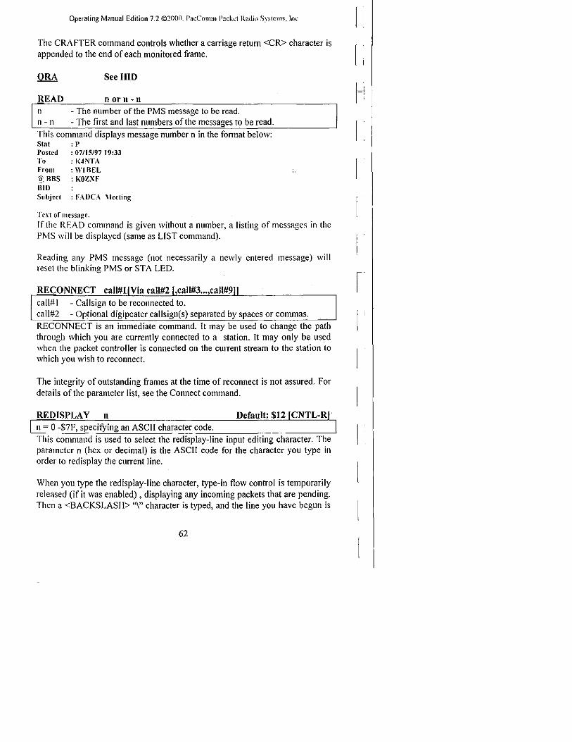
Operating Manual Edition 7.2 ©~OOD. P;lcComm P:Kkd RadiI) S~·stem~.lnc
The CRAFTER command controls whether a carriage retum <CR> character is [ 'I
appended to the end of each monitored frame,
See HID
READ n orn- 0
n - The number of the PMS message to be read. n - n - The first and last numbers of the messages to be read,
This command displays message number n in the format below: Stat : P Postcd : 07115/97 19:33 To : K4NTA From : WI BEL ~, RRS : KOZXF DID Subject : FA DCA \lccting
Text ofmcssage. If lhe READ command is given without a number, a listing of messages in the PMS will be displayed (same as LIST command).
Reading any PMS message (not necessarily a newly entered message) will reset the blinking PMS or STA LED.
call# I - Callsign to be reconnected to. call#2 - Optional digipeater callsign(s) separated by spaces or commas. RECONNECT is an immediate command. It may be used to change the path through which you are currently connected to a station. It may only be used when the packet controller is connected on the current stream to the station to which you wish to reconnect.
The integrity of outstanding frames at the time of reconnect is not assured. For details of the parameter list, see the Connect command.
REDISPLAY n Default: $12 n = a -$7F, specifYing an ASCII character code. This conrnland is used to select the redisplay-line input editing character. The parameter n (hex or decimal) is the ASCII code for the character you type in order to redisplay the current line.
When you type the redisplay-line character, type-in flow control is temporarily released (if it was enabled) , displaying any incoming packets that are pending. Then a <BACKSLASH> "\" character is typed, and the line you have begun is
62

Operating Manual Edition 7.2 ©lill!O. Pa;:CllllHn PuiJ·;C"l R:ldio S):;km~. (llC
redisplayed on the next line. If you have deleted and retyped any characters, only the final fonn of the line is shown.
Use the redisplay-line character to see a "clean" copy of your input with a printing tenninal afier deleting characters. If you have set BKONDEL OFF, deletions are designated with <BACKSLASH> characters, rather than by trying to correct the input line display.
REMOTE Default: OFF ON - Remote commanding function is enabled. OFF - Remote command function is disabled. This command enables and disables the Remote Commanding feature, which allows complete setup and control of a packet controller over an RF link.
When REMOTE is set ON and RMTCALL is set, a remote connection may be made to the TNC's RMTCALL to issue and view the output from TNC commands. All commands may be executed remotely except:
• No callsign changes for MYCALL or RMTCALL will be honored. • PMS should not be accessed. Some PMS commands may function
properly under these conditions, others may fail. The proper way to access all PMS commands is by connecting to the PMS callsign and using the Remote SYSOP function.
• You should avoid use of the DISPLAY command and instead lise subsets of that command, such as DlSP H, DlSP T, etc. If you use the DISPLAY command you will get approximately 300 bytes of data and then nothing else. Sending a <CR> (empty frame) will restore the cmd: prompt.
• The HELP command (not available on all products) is subject to the same constraints as the DlSPLA Y command.
REMSYSOP Default: OFF ON - The MYPCALL is allowed SYSOP privileges over the air. OFF - The MYPCALL is not allowed SYSOP privileges over the air. When REM SYSOP is ON, the callsign contained in MYPCALL is allowed to
READ and KILL any message via the radio port. This allows the SYSOP to remotely manage the message base in the PMS equipped packet controller.
RENUMBER RENUMBER is an immediate command which allows the PMS SYSOP to renumber the messages currently in the PMS message base. The messages will be renumbered starting with the number I.
63

Operating Manual Edition 7.2 ©~O(JO. P:1cColTIm Packt.:( Radin S\"~lelm.lnc.
RESET This an immediate command. lt resets all parameters to factory default settings and re-initializes the packet controller.
NOTE: All customized parameters, heard lists, and PMS messages will be lost when the TNC is RESET.
To re-initialize the packet controller using battery-backed RAM parameter values, use RESTART or tum the controller off and on.
RESPTIME n Default: 0 n ~ ° -250, specitying lOOms increments.
This command sets a minimum delay imposed on acknowledgement packets. This delay runs concurrently with DWAIT and any random wait in effect.
This delay may be used to increase throughput during file transfers when the sending packet controller usually sends the maximum number of full-length packets. If the sending packet controller does not llave a packet ready in time to prevent transmission ITom being stopped temporarily, the acknowledgement of earlier packets may collide with the final packet of the series. If the receiving packet controller sets RESPTlME to 10, these collisions will be avoided.
RESTART RESTART is an immediate command which re-initializes the packet controller [ !
using the bbRAM parameters. The effect of this command is the same as turning the packet controller OFF then ON. RESTART does not change the parameters in bbRAM. See RESET.
RETRY n Default: 10 n = 0 - 15, specifying the number of retransmissions. Unacknowledged frames are re-transmitted n times Cn tries) before the operation is aborted. A value of ° for n specifies an infinite number of retries. If the number of retries is exceeded, the packet controller goes to the disconnected state and the following message is presented:
***retry count exceeded ***DISCONNECTED
The current number of tries is given by the TRIES command.
64

Operating Manual Edition 7.2 ©2i)0(J. PacC,lIllJTI Pac her n.ldio Sy"t.:nb. Inc
RFNPMS call# I - Call sign of PMS station to be connected to. call#2 - Optional callsign of station to be digipeated through.
This command causes the PMS to connect to a switch or node (call# I) via no more than one digipeater (call#2). The callsign string may not exceed 23 characters. Once the connection exists, the PMS sends the node the connect string contained in NODETEXT to cause the node to connect to the desired PMS station. Once the connection to the slave PMS is established, the slave PMS is commanded to upload all messages marked for forwarding.
If the station connected to by the RFPMS command is not a PMS station capable of forwarding messages, or if a forwarding protocol error is detected, automatic disconnection occurs.
RFPMS call#1 - Callsign ofPMS station to be connected to. call#2 - Optionalcallsign of station to be digipeated through. This command causes the PMS to connect to another PMS station (call# I) via no more than one digipeater (call#2). The callsign string may not exceed 23 characters.
Once the connection to the slave PMS is established, the slave PMS is commanded to upload all messages marked for forwarding. If the station connected to is not a PMS station capable of forwarding messages, or if a forwarding protocol error is detected, automatic disconnection occurs .
. _ RMT<:A'(,!; __ . ______ ~_~_!!I~_!'L ________________ .. _ .. __ . _____________________ J)_eX~IJI_t: __ b_'alll< _________________ _ ! call - Callsign of the packet controller. ! ! n - 0-15, an optionally specified sub-station ID (SSID). i l _____________________________________________________ • ____________________ > _______ •• ____________________ • ______________________________ J
This command sets the call sign of the Remote Command Function of the packet controller. It should NOT be identical to MYCALL.
The password protected remote commanding allows complete setup and control of the packet controller over the RF link. See the REMOTE command.
RTCSYNC Default: OFF ON - Packet controller seconds are updated fi'om GPS sentence. OFF - Packet controller seconds are updated by controller finnware. The RTCSYNC (Real Time Clock Synchronization) command updates the seconds field of the packet controller's software clock to match the time received from GPS satellites. The minutes and hours are not affected thus preserving the local time zone entered by the packet controller operator.
65

(Jper;lling \ltllllIU[ Ediiion 7.2 '~20(jO. Pac('ollllH P<lckd Radin S .... :-itcm". Inc
The clock is updated to GPS time once per minute if GPSSLEEP is OFF, and on every fix ifGPSSLEEP is ON. RTCSYNC uses the $GPGGA sentence, but it is not necessary for any of the GPS capture buffers to be scanning for the GGA sentence. Of course the GPS receiver must output the GGA sentence.
If a hardware clock chip is installed it is automatically updated ITom the b" software clock by the packet controller finn ware. I ;
RXBLOCK Derault: OFF ON - The controller sends data to the tenninal in RXBLOCK fonnat. OFF - The controller sends data to the tenninal in normal formal. RXBLOCK is designed for automated operations, such as packet bulletin board stations. It helps such systems discriminate between data received from the connected station and packet controller generated messages.
Correct operation of RXBLOCK is dependent on the A WLEN parameter being set to 8 bits because the character FF hex marks the beginning of a received data un it header.
When RXBLOCK is on, data ITom other stations will be sent ITom the packet I' controller in the following format:
................ 1 $FF LO 1 Ll PIDI DATA
................ The fields above are defined as follows:
Prefix .............. $FF::= A character with all 8 bits set Length ............. LO::= The high order data length, length and PID fields ........................ logically ORed with $FO ........................ LI ::=The low order data length, length, and PID fields PID ................. PID::= The Protocol Identifier byte received for the ........................ following data field Data ................ DATA::=[Optional], variable data length
For best operation, parameters like AUTOLF, MFILTER, etc should be set to OFF to prevent uncertainties in the size of the data field.
SB This is an extension of the PMS SEND command. SB causes the message status to be marked with a B designator denoting BULLETIN.
Refer to the SEND command for detailed instructions.
66

Operating Manual Edition 7.2 ©2000. Pm::ClllllTTI Packc! R:ldiu S)'skn;~. 1Il(_
SCREENLN n Default: 0 n = 0 - 255, specifYing the character with ofthe tenninal screen.
This command fonnats tenninal output by specifYing the length of each line of text displayed. A <CR><LF> sequence is sent to the tenninal in Command and Converse Modes after n characters have been sent. N = 0 inhibits this action.
If the computer automatically fonnats output lines, leave SCREENLN set to O.
SEND to-call-o fa) call-n $ BID to-call - Callsign to which you wish the message addressed. @-call - The "home BBS" callsign of the station to which the message is sent
(if known). n - Optional SSID. $ BID - Optional Bulletin Identifier.
This command begins the procedure for creating a message addressed to "tocall". Addressing messages to "ALL" is pennitted. If the operator does not enter a callsign, the message will be addressed to MYPCALL, the PMS callsign. The HOMEBBS callsign (if known) should be included as shown above in the command fonnat as @call. The @ symbol must be typed between the callsigns, as it is not automatically provided.
The BID (Bulletin Identifier) is entered beginning with a US Dollar Sign ($). The remainder of the BID is tree-form and is filled according to local practice.
Subject: A maximum of 70 characters may be entered with a <CR>. If too long a subject is entered, the PMS will truncate the part exceeding 70 characters. Only 28 characters of the subject are displayed when the messages are listed, therefore users accessing the PMS will only see the first 28 characters of the subject until they read the message.
Text: End each line with a <CR>. End the message by typing <CR>, lex, or CNTL-Z at the beginning of a new line.
Message size is limited only by the unused memory space available in the PMS message storage area. [fthat space is exceeded, the PMS will display:
-Buffer overflow
When the message has been saved, the PMS will display:
Message saved as Msg#n
67

Operating Manual EdiLion 7.2 ©:!O(Jf). PaCCOrTIlll PJcb':l Radio S~·slcm~. lnc
SENDPAC n Default: SOD <CR> n ~ 0 - $7F, specitying an ASCII character. This command selects the ASCII code (parameter n) for the character that will force input to be packetized and queued for transmission in Converse Mode. You may enter the code in either hex or decimal.
For conversation, set SENDPAC ~ $00 and CR ON. This causes packets to be sent at natural intervals, and causes the <CR> to be included in the packet. If CPACTIME is ON, set SENOPAC to some value not ordinarily used (i.e. <CNTL-A», and set CR OFF. This allows forcing packets to be sent, but will not result in extra <CR> characters being transmitted in the text.
• SILENT Default: OFF ON - The packet controller does not output prompts or messages. OFF - The packet controller sends all sign-on messages and prompts. This command disables all the initialization (sign-on) messages, error messages and prompts for applications which would be disturbed if the messages were sent.
This is useful when the packet controller is attached to a serial printer, data logger, or other device which expects to receive no control commands or informational messages and treats all output from the controller as 'user data.'
SILENT does not affect the echo function which must still be separately be controlled by the ECHO command.
SLOTS Discontinued Command The SLOTS command is no longer supported in PacComm firmware. The command may be present in some finnware versions, but is not operative.
SLOTTIME n Default: 1 n ~ 0 - 255, specitying lOOms increments. SLOTTIME is part of the P-Persistence channel access technique selected by the PPERSIST command.
SLOTTIME selects the length of the delay between attempts to access the channel. Larger SLOTTIME values lower the packet controller's priority in accessing the channel.
.SOFTDCD Default: See Below ON - The OCD signal is derived tram firmware OFF - The OCO obtained tram the modem hardware. This parameter should be set to ON when using a TNC-220 which is NOT equipped with a tuning indicator.
68

Operating Manual Edition 7.2 ©2flOfl. Pacl...\ll1lm P<tc!,:cr Radiu Sy~h:I1l~ Inc
SOFTDCD MUST be set to OFF for proper operation of all models which do not use the 8530 SCC. Use of the SOFTDCD command is not recommended for any model except the TNC-220.
SP This is an extension of the PMS SEND command. SP causes the message status to be marked with a P designator for personal or private. Refer to the SEND command for detailed instructions.
SR n n = Number of PMS message which is replied to. SR stands for Send Reply. The message number must be included. The SR command is not used to send a reply to the most recently read message. If no message number is included, the following message is displayed:
parameters are missing
SR automatically reverses the TO and FROM callsigns ITom message number n and enters the same subject in the reply message, preceded by "re:". The proper entry is made in the @BBS field if this information can be determined ITom the received message. When the proper entry for the @BBS field can not be reliably determined, use the EDITHDR command to edit the @BBS callsign if one is needed.
In the example below, message 12 was generated by giving the command:
SR 11
Msg# Stat Dale Time To It PR OS/28/97 10:04 N4UQR 12 PR 05128/97 t2:49 W4DPII 11206 Bytes free Next message Number 13
ST
From W4DPII N4(;QR
@DBS @W4DPII @W4DPII
Subject Meeting Meeting
This is an extension of the PMS send command. ST causes the message status to be marked with a T designator for National Traffic System (NTS) traffic. The text of such a message should be filled with an NTS formatted message. Refer to the SEND command for detailed instructions.
START n Default: $11 {CNTL-Q}
I n = 0 - $7F, specifYing an ASCII character code. The START command selects the terminal Restart character, which is used by the terminal to restart the output ITom the TNC to the terminal after it has been halted by receipt of the terminal Stop character. The code may be entered in either hexadecimal or decimal.
69

Operating Manual Edition 7.2 ©2000. PacComrn Pa:.;k~l Radifl ~y:'(Clll<;;. In~.
If the terminal Restart (START) and terminal Stop (STOP) characters are set to SOO, software flow control to the packet controller is disabled, and the packet controller will only respond to hardware flow control.
If START and STOP are set to the same character, the packet controller will alternately start and stop data flow upon receipt of the character.
STATUS
$00 - Disconnected state. SO I - Connect in progress. $03 - Discormect in progress. $04 - A connection exists and all fi'ames are acknowledged. $06 - A connection exists and unacknowledged trames exist.
STA TUS is an immediate command which returns a hexadecimal value indicating selected link parameters on the current stream.
STEXT text Default: blank text - a string of up to 80 characters ending with a carriage return. STEXT contains the text which is sent as the PMS custom sign-on message. If STEXT is blank, no message is sent. The default text is blank, i.e. no message. You can send multiple-line messages in the beacon by including carriage return <CR> characters in the text preceded by the PASS character.
If you enter a text string longer than 80 characters, an error message wiII appear and the command wiII be ignored.
LOGONMSG controls the standard sign-on message and is not related to STEXT.
STOP n
n ~ 0 - $7F, specifying an ASCII character.
The STOP command is used to set the value of the character used as the ternlinal Stop character. The terminal Stop character stops output from the packet controller to the terminal, i.e. halts scrolling. The code may be entered in either hexadecimal or decimal.
Output is restarted with the terminal Restart character, which is set by the START command. If the terminal Restart (START) and terminal Stop (STOP) characters are set to $00, software flow control to the packet controller is disabled and the controller wiII only respond to hardware flow control. If START and STOP are set to the same character, the packet controller will alternately start and stop data flow upon receipt of the character.
70
I i I

Operating Manual Edition 7.2 ©2tWO. PW:Clll111n Pad.CI f{~dju Sysienb. [ni:.
Default: OFF
- callsign of other station is displayed. - callsign of other station is not displayed.
The STREAMCA command is used to enable the display of the connected-to station callsign after the stream identifier. This option is useful for operators attempting to operate multiple simultaneous connections. In the example below, the characters inserted by enabling STREAMCA are shown in bold type: STREAMCA ~ ON STREAMCA ~ OFF
IA hi howie IA:K4NTA:hi howie hello ted how goes it? Hello ted how goes it? IB:N7CL:*** CONNECTED to N7CL IA Ted, AZ on other stream
IB *** CONNECTED to N7CL IA Ted, AZ on other stream
What looked like "IB" appears as "IB:<callsign>:" with STREAMCA ON.
.STREMCALL Default: OFF
An alternate spelling of STREAMCA LL in some fimnware versions.
See STREAMCA above .
• STREMX Default: OFF
ON - Enable streamswitch character display at the start of each line. OFF - Disable streamswithc character at the start of each line. When STREMX is ON, each text lille of a received packet will have the streamswitch character (I) and the letter denoting which stream is active.
With STREMX ON: ICThis is an example ofSTREMX ON. With STREMX OFF: This is an example ofSTREMX OFF.
STREAMDB Default: OFF
ON - double all received STREAMSW characters. OFF - do not double received STREAMSW characters. This command is used to display received STREAMSW characters by "doubling" them. This is useful for distinguishing between STREAMSW characters received from other stations and those generated by the packet controller. With STREAMDB ON, and STREAMSWitch set to "I", the following is an example of what may be displayed by your packet controller:
II this is a test.
In this case the sending station actually transmitted: I this is a test.
This same stream with STREAMDB OFF would appear as: I this is a test.
71

Operating Manual Edition 7.2 ©~O(jO. PacColTIm Packet R(ldil) "iystt:1ll5. Inc.
STREAMSW n Default: $7C <I> [ n - 0 -$FF, specitying an ASCII character.
This command selects the character to indicate a new stream is being addressed. Set it to a value seldom used in normal text. NOTE: The STREAMSW character MUST NOT be the letters A through Y.
The character can be PASSed in Converse Mode but flows through as data in Transparent Mode. Thus the outgoing stream cannot be changed while "online" ill Transparent Mode. You must enter Command Mode to switch streams.
Also see the STREAMDB and STREAMCA commands.
TKILLOK Default: OFF
ON - traffic messages may be killed byanyone. OFF - traffic messages follow normal rules. The TKILLOK ON corrunand allows any user on the radio port to kill an NTS (T) type of message in the PMS.
TKILLOK OFF requires the connected PMS user's callsign to match the message callsign before it will allow the message to be killed. This command does not affect the ki II function on the terminal port.
TPERSIST Discontinued Command The TPERSIST command is no longer supported in PacComm firmware. The command may be present in some finnware versions, but is not operative.
TRACE Default: OFF ON - Trace mode is enabled. OFF - Trace mode is disabled.
TRACE enables the protocol debugging function. TRACE ON displays alI received frames in their entirety including all header information. A trace display will appear in four columns on an 80 column display.
IRANSPARENT TRANSPARENT is an immediate command which causes the packet controller to enter Transparent conmode. The current link state is not affected.
Transparent Mode is primarily useful for computer communications. In this mode the "human interface" features such as input editing, echoing of input characters, and type-in flow control are disabled and all control characters are passed without action.
To exit the Transparent Mode, enter <CNTL-C> if the link state is disconnected, and three <CNTL-C>'s if the link state is connected.
72

Operating Manual Edition 7.2 ©2l10tL Pa;:CllllllTI PHd:!?! f{:ldiu SySh:ms. [ll~·.
TRFLOW Default: OFF ON - Transparent Mode tenninal flow control can be enabled. OFF - Transparent Mode software flow control is disabled. TRFLOW allows software flow control to be used in Transparent Mode on data received over the serial port ftom the tenninai.
If TRFLOW is ON, and START and STOP are non-zero, Transparent Mode software flow control is enabled for the serial port. The packet controller will look for the START and STOP characters in the data stream and treat them as flow control commands. Thus truly transparent operation is not possible.
IfTRFLOW is OFF, or START and STOP are set to $00 (disabling response to the tenninal's Stop and Start characters) hardware flow control must be used by the tenninal and all characters received by the packet controller are transmitted as data resuiting in completely transparent operation.
Unless TXFLOW is ON, only hardware flow control is available to the packet controller to control output from the tenninal.
TRIES n Default: none I n = value to force tries counter to.
This command is used to retrieve the count of the "RETRIES" on the currently selected input stream. Ifis useful in obtaining statistics on the perfonnance ofa given path or channel.
If the packet controller has an outstanding, unacknowledged frame, TRIES will return the current number of tries (or attempts at delivery of the packet); ifthe packet controller has no outstanding, unacknowledged frames, it will return the number of tries that were required for the previous frame. If RETRY is set to zero (0), the value returned by issuing a TRIES command will always be zero.
If followed by an argument, TRIES will force the "TRIES" counter to the entered value. This IIsage is NOT recommellded .
• TRMAX n Default: 3 n - 0-255 specifYing the number of seconds to wait for channel allocation. This command is part of the support for trunked radios. See TRUNK for a complete explanation ..
In trunking systems where PTT is held on continuously until a channel is allocated, (which requires the command TRSTYLE ~ OFF) TRMAX sets the length of a timeout period for the PTT in case no channel allocation signal is received.
73

Operating Manual Edition 7.2 ©:!(J(Jli. P.1cComm f'il.:kcl Radio .\~·stcm<;.. 1rlC-
+TRSENSE
ON OFF
- Johnson/Uniden (active low) - Motorola (active high)
Default: OFF
This command is part of the support for tronked radios. See TRUNK. I
This command selects whether the channel allocation signal received via the b RFDCD input is to be active high or active low. I .
+ TRSTYLE Default: ON
ON - PTT is off while waiting for channel allocation. OFF - PTT is on continuously until a channel is allocated.
This command is part of the support for trunked radios. See TRUNK.
TRSTYLE selects the type of keying algorithm used when TRUNK is ON.
TRSTYLE OFF holds the PTT line active while the radio is undergoing channel allocation. If the channel allocation signal is not received before TRMAX expires. the keying line is released and the cycle is reinitiated.
TRYSTYLE ON activates the PTT line to request a channel, then drops the PTT until a channel allocation signal is received.
+ TRUNK Default: OFF ON - Use the radio keying algorithm selected by TRSTYLE. OFF - Use conventional PTT protocol. This command activates special keying algorithms to support trunked radio systems (Specialized Mobile Radio - SMR). The TRSTYLE parameter determines which keying algorithm is enabled by TRUNK.
Set TRUNK OFF for conventional radios.
TXDELAY n Default: 15 I n = 0 -120, specifying IOms intervals.
This value tells the packet controller how long to wait after keying up the transmitter before sending data. Some startup time is required by all transmitters to put a signal on the air; some need more, some less.
The correct value for a particular rig should be determined by experimentation. The proper setting of this value may also be affected by the equipment of the station being communicating with. If loud, clear signals are not decoded, suspect the TXD of the transmitting station is set too low (or the station is overdeviating!)
74

Operating Manual Edition 7.2 ©2fl(lO. PacClllllm Pachcl R;,Jiu S;.sI-..::nl~. !lk
TXDELAYC n Derault: 12 n ~ 0 - 120 specifying additional transmit delay character times. TXDELA YC is used to "fine tune" the transmit delay. It is used in conjunction with TXDELA Y to allow a link to be set for maximum perfonnance.
The sum of TXDELA Y and TXDELA YC will automatically adjust the radio key-up time for various RF data rates. With this method of transmit delay timing, a user may operate at various RF data rates without have to alter TXDELA Y, as long as the same radio equipment is used.
TXDELAY should be set for the longer of the times it takes the radio to switch from receive to transmit or vice versa. That setting should be the slower of the originating TNC's radio and the remote TNC's radio.
During TXDELAY, zero bytes are sent. This allows the remote TNC to synchronize with the data stream. Flags are sent for TXDELA YC character times to start the frame.
IfTXDELA YC ~ 0, the mc will respond as ifTXDELA YC ~ I.
TXFLOW Default: OFF
ON - Transparent Mode software flow control is enabled. OFF - Transparent Mode software flow control is disabled. TXFLOW controls whether Transparent Mode software flow control is enabled for data being transmitted from the packet controller to the temlinal.
If TXFLOW is ON, the setting of XFLOW is used to detennine the type of flow control used in Transparent Mode. If TXFLOW is OFF, the packet controller will use hardware flow control and all data sent to the terminal remains fully transparent.
IfTXFLOW and XFLOW are ON, the packet controller will use the TNC Start and Stop characters (specified by XON and XOFF respectively), to control to control input to the terminal.
Unless TRFLOW is ON, only hardware flow control is available to the computer Itenninal to control output from the packet controller. If the mc Start and Stop characters (XON and XOFF are set to $00, hardware flow control is always selected regardless of the setting ofTXFLOW.
75

Operating Manual Edition 7.2 ©200n. P:lCCOlTIllI Packt:{ Radi\1 Systems. Inc_
TXUIFRAM ON OFF
- UI frames may be transmitted. - No UI frames wiII be transmitted.
Default: ON
This command eliminates the dumping of un sent frames as UI (Unnumbered
I i
Infonnation or Unprotocol) frames when a connection fails. lt is useful to 1_'.' operators of Packet Bulletin Board Systems (BBS).
TXUIFRAM ON will also prevent sending UI frames from the keyboard in Converse Mode, but will not interfere with the sending of beacons.
UIBEACON Default: OFF ON - The packet controller sends BTEXT in response to a UI poll. OFF - The controller does not respond to a UI poll. When UlBEACON is ON, and a UI frame is received addressed to MYCALL, the BTEXT will be sent immediately and the beacon timer (if enabled) will be reset to the full beacon period.
UILOC Default: OFF ON - The TNC sends the GPS capture buffers in response to a UI poll. OFF - The TNC does not send buffers in response to a UI poll.
When UILOC is ON and UIBEACON is ON, and a UI frame is received addressed to MYCALL, the GPS capture buffers (L TEXT etc.) will be sent immediately and the Location timer (if enabled) will be reset to the full location period.
oUIMODE Default: OFF ON - The packet controller enters CONMODE on power up. OFF - The packet controller enters Command Mode on power up. The UIMODE controls the initial state of the packet controller when power is first applied. When UIMODE is OFF, the packet controller initializes to the Command Mode and waits for a command from the asynchronous serial port.
When UIMODE is ON, the packet controller initializes into the CONMODE without any commands from the serial port. Any characters received from the serial port will be packetized and transmitted as UI frames.
In other words, the TNC wiII not come up with a CMD: prompt ifUIMODE is ON, but will instead be in either CONYERS or TRANS mode as specified by. CONMODE. The TNC wiII be ready to send UI frames generated by APRS or a telemetry source without any operator intervention or additional setup.
Note: The DATAMODE command replaces UIMODE in some models.
76

Operating Manual Edition 7.2 ©200(J. PacCllllHn Pach.c1 Radio S:'st<.::ms. Inc.
omWlndow Default: OFF
ON - The UIWINDOW function is enabled. OFF - The UIWTNDOW function is disabled.
This command enables or disables the UIWINDOW function i.e. the WINOpen and WINClose commands.
UIWINDOW allows setting of time bands when location beacons will be sent. When UIWIndow is ON, location beacons will be sent at the rate specified by the LOC command beginning at the first time specified in WINOPEN and ceasing at the first time specified in WIN CLOSE, beginning again at the second time in WINOPEN until the second time in WINCLOSE, etc.
For example if WINOPEN ~ 0730 1700 and WTNCLOSE ~ 0830 1800 location beacons will be transmitted during daily commuting hours of 0730-0830 and 1700-1800.
,call#3, ... ,c.II#9 Default:C call#1 - Cailsign to be placed in the TO address field. call#2-9 - Optional digipeater call list, up to eight calls. This command sets the digipeat and destination address fields of packets sent in the unconnected (UNPROTOcol) mode.
Unconnected packets are sent as Unnumbered Information (UI) fi-ames with the destination and digipeat fields taken fi-om call# I through call#9 options. The default destination for unconnected packets is CQ. Callsigns may be separated by either spaces or commas. See the CONNECT command for greater detail about entering a callsign and digipeater string.
It is not nOimally important what callsign is set into UNPROTO for UIMODE/DATAMODE communication. However see the commands DGPSCALL, QRA, UlBEACON, UILOCATION which are dependent on the UNPROTO callsign.
USERS n Default: 1 n ~ 0 - 5, the total number of connections allowed. USERS sets the maximum number of connections allowed. USERS affects only the manner in which incoming connect requests are handled, it has BO
effect on the number (or handling) of connections initiated by the packet controller. For example:
USERS 0 allows incoming connections on any free stream USERS I allows incoming connections on stream A only USERS 2 allows incoming connections on streams A & B
77

Operating Manual Edition 7.2 ©20{Jii. P:](;Comm P:1.ckd Radu) ";.r~tclll'". Inc.
USERS 5 allows incoming connection on steams A-E.
The number of possible streams varies among products.
UTC ONIOFf or 'yeslNo Default: OFF The UTC command enables the TNC time of day clock to be updated with GPS UTC time in the HHMMSS fields. If F1XTYP is set to 5 for the $GPRMC sentence then the date is also updated to the GPS UTC date.
The R TCSYNC command must be set to ON for UTC to take effect.
YERSION The VERSION command causes the entire packet controller firmware sign-on banner to be displayed, including the features supported, firmware release number and date .
• WATCHDOG n Default: 0 n ~ 0-65536 specifying the number of seconds between automatic restarts.
If no station has connected for n seconds, the packet modem will initiate a RESTART command using the parameters saved in RAM. Ifn ~ 0 the function is disabled.
This command is useful for packet modems installed at limited access sites and when using remote commanding. If the packet modem fails to accept a connection for n seconds, it will restart itself. This may overcome difficulties experienced as a result of power supply transients, RF fields, or inappropriate remote commands.
'WINOPEN text Default: blank WINOPEN works with the command UlWINDOW.
WINO PEN text is one or more times expressed in 24hour format which denote the beginning times for actuation of LOCATION beacons controlled by the UIWINDOW command. Times should be separated by a single space. For example: 1030120014001700 .
• WINCLOSE text Default: blank WINOPEN works with the command UIWINDOW.
WINCLOSE text is one or more times expressed in 24hour format which denote the ending times for actuation ofLOCA TlON beacons controlled by the UIWINDOW command. Times should be separated by a single space. For example: 1040121014301900.
78
I :
r

Operating Manual Edition 7.2 ©2noo, »ilCCtlmm Pad:.;:! R;ldiu !)~:-;h:m~, Inc,
XFLOW Default: ON ON - XON/XOFF (software) flow control is enabled. OFF - XON/XOFF flow control is disabled. If XFLOW is ON, the computer or terminal is presumed to respond to the packet controller START and STOP characters, set by XON and XOFF.
If XFLOW is OFF, the packet controller will communicate flow control commands via RTS.
XMITOK Default: ON ON - Transmit functions are enabled. OFF - Transmit functions are disabled. When XMITOK is OFF, transmitting is inhibited. All other functions of the packet controller remain the same, i.e. the packet controller generates and sends modulated audio to the radio, but does not key the radio PTT line.
This command is useful for safety purposes. It ensures that the packet controller does not transmit during the adjustment of radio equipment, but allows the controller to continue to monitor the channel.
XOFF n Default: $13 n ~ 0 -$7F, specifying an ASCII code character. This command selects the TNC STOP character (hexadecimal or decimal), which is set from the packet controller to the computer to stop input from that device. This character would normally be set to <CNTL-S> for computer data transfers. If you want notification when the buffers are filled in Converse Mode, set this character to <CNTL-G> ($07), which rings the terminal bell.
See also XFLOW.
XON n n ~ 0 -$7F, specifying an ASCII code character. This command selects the TNC START character (hexadecimal or decimal), which is set from the packet controller to the computer to stop input from that device.
This character would normally be set to <CNTL-Q> for computer dOla transfers. If you want notification when the buffers are filled in Converse Mode, set this character to <CNTL-G> ($07), which rings the terminal bell.
See also XFLOW.
79

(Jper:Hing \.fallual Edltion 7.'2 ::~:W{Ji), P;lI.:{'omlli P:lck<
Operating Manual Edition 7.2 ©2000. Pw::Clll11m Pade! R:1diu Syst~ms. IIli,'
you will receive this message if you attempt to enter one of these data transfer modes before some of the packets have been successfully transmitted.
Command Mode Error Messages
When a mistaken command is given to the packet controller, one of the following messages may be displayed.
? parameter The command was typed correctly, but the remainder of the line couldn't be interpreted.
? call The callsign argument does not meet the packet controller requirements for call signs. A cal1sign may be any string of numbers and letters, including at least one letter. Punctuation and spaces are not allowed. The sub-station 10, if given, must be a (decimal) number from 0 to 15, separated from the call by a hyphen.
? clock not set The command DAYTIME was given to display the date and time but the clock is not set. DAYTIME sets the clock if used with the daytime parameters, and displays the date and time if used alone.
? unknown command The first word typed is not a command or a command abbreviation.
? not enough Not enough arguments (parameters) for the command given.
? range A numeric argument for a command was too large.
? too long Too long a command line was entered, and was ignored. This might happen when you exceed the maximum number of allowed characters in a text field. If this error appears, the previous value of the text field has not been changed.
?too many You gave too many arguments (parameters) for a command.
Link Status Messages
The following messages give the status ofAX.25 connections the packet controller is involved in. You may check the link status by giving the CONNECT command without parameters. If you do this when your packet
81

Operating Manual Edition 7.2 ©:!(J(jo. P:lCCOrnlll P:1ckd Radio S~·stcms. Inc.
controller is not in the disconnected state, the packet controller will display the link status but will take no other action.
The packet controller will infonn you whenever the link status changes. The link status may change in response to a command (CONNECT or DISCONNECT), a connect or disconnect request ITom another station, a disconnect due to the retry count being exceeded, an automatic time-out disconnect (CHECK) , or a protocol error.
?VIA This message appears if you attempt to enter more than one call sign for the CONNECT or UN PROTO commands without the VIA keyword.
? not while connected An attempt to change MYCALL, AX25L2V2 or PORT was made while in a connected or connecting state.
? not while disconnected Attempting to perfonn an operation that can only be done while connected. This message may appear when issuing a RECONNECT or CON PERM command.
? already connected to that station An attempt was made to connect to a station to which a connection exists or is being built. The multi-connect software will not pennit you to connect to the same station on different streams.
Link state is: CONNECTED to call#1 (VIA cal1#2 (.call#3 .... call#9]( This display shows the station your packet controller is connected to and the digipeater route if any. The callsign sequence is the same sequence you would enter to initiate the connection.
*** LINK OUT OF ORDER, possible data loss (optional daytime stamp) This message is issued upon failure of a CON PERMed link.
Link state is: DISCONNECTED No connection currently exists. You may issue the CONNECT command to initiate a connection.
Link state is: CONNECT in progress You have issued a connect request, but the acknowledgment from the other station has not been received. If you issue a DISCONNECT command, the connect process witI be aborted.
82

Operating Manual Edition 7.2 ©20(lU. Pac(':Lllllln Pader l~aJjo S) "t~lll;;. Ille.
Link state is: DISCONNECT in progress A DISCONNECT command was issued, but the acknowledgment has not been received. Giving a second DISCONNECT command will cause the packet controller to go immediately to the disconnected state.
Link state is: FRMR in progress The packet controller is connected but a protocol error has occurred. An improper implementation of the AX.25 protocol could cause this state to be entered. The packet controller will attempt to re-synchronize frame numbers with the TNC on the other end, although a disconnect may result. Connects are not legal in this state, and a disconnect will start the disconnect process.
*** CONNECTED to: call#1 (VIA call#2 (,call#3 ... ,call#9]] This message appears when the packet controller goes from the "disconnected" or "connect in progress" state to the connected state. The connection may be a result of a CONNECT command you issued, or of a connect request packet received from another station.
*** connect request: coll#1 (VIA coll#2 (,call#3 ... ,call#9]] This message indicates that the packet controller has received a connect request from another station which it has not accepted. This can happen if you have set CONOK OFF or if you are already connected to another station. When the packet controller types this message it also sends a DM packet (busy signal) to the station that initiated the connect request. If the packet controller rejects a connect request because you have set CONOK OFF, you can issue your own request to the station that called.
*** DISCONNECTED This message is displayed whenever the packet controller goes to the disconnected state from any other link state. This message may be preceded by a message explaining the reason for the disconnect.
*** retry connt exceeded *** DISCONNECTED This message is given if the disconnect was caused by a retry failure rather than by a disconnect request from one of the stations.
*** callsign busy *** DISCONNECTED This message indicates that your connect request was rejected by a DM packet (busy signal) from the other station. That might mean CONOK is OFF or the station is already connected to another station.
83

Operating Manual Edition 7.2 ©20(Jn. PacCom!ll Packet Radin Sy~lC1ll5. Inc_
FRMR frame jusl senl: FRMR senl:slring The packet controller is connected, and a protocol error has occurred. The packet controller has sent a special FRMR packet to attempt to re-synchronize ITame numbers with the TNC on the other end. The string is replaced with the ~ .•. hex codes for the three bytes sent in the information part of the FRMR ITame. I: Th is message will not appear if your packet controller is in Transparent mode.
FRMR rcvd: This message is followed by a display of the FRMR packet received in the trace display format. (See the TRACE command.) This message will not appear if your packet controller is in Transparent Mode.
PMS Response Messages This section describes messages generated by the Personal Message System (PMS). The term USER is applied 10 an over-the-air PMS user, and SYSOP 10 the packet operator.
[PMS-3.2-C$] SlDstring sent by PMS during forwarding sessions to the HOMEBBS.
*** CONNECTED TO (PMS cansign) Logged 00 10 (pMS cansign)'s Personal Message Syslem (optional message line copied from STExt - may be blank) CMD(BIH/JIKIKMILIMIRIS/SRNI?» This text is sent when a user connects to the PMS. Either or both of the message lines may be displayed based on PMS parameter settings.
*** PMS-callsigo busy *** DISCONNECTED If the Sysop is entering a message, or PMS is OFF, a user attempting to connect over the air will receive a 'busy' message.
PMSIS BUSY This message is sent if the PMS is in use by an over-the-air user, and the system operator attempts to enter or kill a message or any other action which would alter the contents of the PMS memory area.
MYPCALL's Personal Message Syslem Sent to the connecting station if the PMS parameter LOGONMSG is ON.
You have mail wailing. Sent to a user after PMS log on if mail is addressed TO that callsign.
84

Operaling Manual Edition 7.2 ©21l(lO. Pa;;:Clllllln Pad.c"1 fbdio 5~st~nb. Inc:.
The following display is sent in response to the Help or ? command 1T0m a PMS user. B(ye) H(elp) J(log)
K(iII) KM(ille) L(ist) M(ine) R(ead) S(end)
SB SP SRn ST V(ersion)
Message erased
B [CR] disconnects you from PMS. H [CR] or? [CR] displays this help file. J[CR] displays a list of callsigns heard (optional date/time). K n [CR] deletes message n (only to/from your callsign). KM [CR] deletes all READ messages addressed to your call. L [CR] lists the 10 latest messages. M [CR]lists the 10 latest messages to/from your call sign. R n [CR] reads message number n. S (callsign) [CR] begins a message addressed to (callsign). Subject: max 28 characters ending with [CR]. Text: End each line with <BS>[CR]<D>. End message by typing lex [CR] or CTRL-Z [CR] at the beginning of a new line. Send Bulletin Send message marked Personal SR n [CR] Sends a reply to message n . Send message ill NTS format. V[CR] displays the software version of the PMS system.
This message is sent or displayed in response to the Kill command which originates from either the Sysop or user.
Message marked for forwarding Response to the Sysop command to mark a message for reverse forwarding.
Message forwarding reset Response to the Sysop command to 'unforward' a message previously marked for forwarding.
Message has been sent to the printer queue Response to the PPRint Sysop command to print a PMS message on the packet controller printer port.
Message saved as Msg # n Response sent or displayed after the completion of 'Sending' a message by either the Sysop or user.
nnnnn Bytes free, Next message Number n Displayed at the end of the LIST display.
85

Operating Manual Edition 7.2 ©~()(Jl). PacCoJnm Packt:! Rmlil..) SY:"lellL~. Inc.
-Logged off *** DISCONNECTED This message as a result of the BYE command being issued by a PMS user.
PMS Error Messages
[PMS CMD ERR] This message is issued when a PMS user sends a command in an improper format, commonly using more than one character of the command name. Sysop command errors receive the nonnal ? unknown command response.
Message not found This message is issued whenever a READ or KILL command is given with an invalid message number by either a user or Sysop.
YOU CANNOT KILL THIS MESSAGE This message is issued when a user attempts to kill a message not to or from his callsign.
YOU CANNOT READ THIS MESSAGE This message is issued when an attempt is made to read a message not addressed to or fi-om the user's callsign, or ALL.
No third party mail allowed When 3RDPARTY is OFF, this message is issued when a user attempts to send a message to other than the PMS (Sysop) callsign.
- Buffer overflow This message is issued when the PMS memory capacity is exhausted and the message being sent has been truncated.
Parameters are missing This message is issued when the EDlTHDR command is used by the Sysop with improper parameters.
You cannot forward a bulletin This message is issued when an attempt is made by the Sysop to mark a bulletin for forwarding.
Entry too long, try again Displayed whenever too many characters are entered at a prompt i.e. too long a BID or Subject entry.
86

Packet Radio Tutorial This chapter shows commands and packet controller responses in boldface type. Commands are boldfaced the first time used in a section and in normal typeface thereafter. The short form of the command is underlined when in text, but not when used in example comman\ts.
First Steps Connect the packet controller to the computer with a properly configured serial cable. Tum the computer on and start the terminal program. Follow the directions for the program you are using to set the computer's baud rate to the speed and settings for the terminal indicated on the Software Release Notes. See the Technical Reference Manual for details.
Tum on the packet controller. You should see the following display.
IA PacComm [modell Packet Controller (c) Copyright 1985-2000 PacComm
AX.25 Level 2 Version 2.0 Features: Release n.n.n Month, Day, Year (Optional custom message line here) cmd:
The first five lines are the sign-on message, which you will normally see Dilly when you power up the packet controller. The line following Features: will contain a list of optional firmware features included in this EPROM. See the Errata for values of n.n.n and the release date for your model of packet controller.
The Command Mode prompt, cmd: will appear when the packet controller is in Command Mode and is ready to accept commands. If you see nothing, switch off the packet controller for a few seconds, then on again. If you still see nothing, verify the wiring and restart the terminal program.
You may use either UPPER CASE (capital letters) or lower case (small letters) when you enter commands. The shortest acceptable form of each command will be shown underlined in Command List of this manual. You must finish each command line with a <CR>, or carriage return character. This may not be mentioned again in the examples below. Before you type the final<CR> of the command, you can correct typing mistakes or cancel the line completely.
87

Operaling Manual Edilion 7.2 ©20011, P;ICCoJnm Pad:''':l Rudill S\·'<;ICJll~_ Inc
\Vhenever the packet controller accepts a command, which changes a value, I ' it displays the previous value to remind you of what you have done, and show the value has been successfully changed. For example, if you type:
emd: XFLOW OFF
you might see the display
XFLOW wasON emd:
If you type something the packet controller can't understand you will get the unrecognized command error message:
?unknown command
If you get a command name correctly, but the arguments are wrong, you will see the message:
?parameter
Beginning Packet Operation This section wiII guide you throngh the basics of packet radio operation with the packet controller. Packet radio has a great deal of power and flexibility, and this section only scratches the surface of the packet station's capabilities. However, it contains the basic infonnation required to begin operation.
Setup Type the text, "MYCALL XXXXXX" following the Command Mode prompt. Of course, you should substitute your station CALL SIGN for XXXXXX. Don't forget the <CR>at the end of the line.
emd:MYCALL XXXXXX was NOCALL emd:
Your callsign wiII be used by the packet controller as its' "address". The packet controller responds with the previous value of the MYCALL parameter, and gives a new Command Mode prompt. Now try typing just the command by itself:
emd:MYCALL MYCALL XXX XXX
88

Operating Manual Edition 7.2 ©20L!(J. PflCCllllln Pnc"ct R:1dio Sys!~m:-.. [nco
This verifies that the packet controller accepted your CALLSIGN. You can see the current value of most parameters by typing the command that sets the parameter followed by a <CR>.
Most commands can be abbreviated. The minimum abbreviation for each command is given in the Commands chapter in this manual. Full length command names are used in this chapter for clarity.
Connected Mode vs. Connectionless Mode Packet communication may be conducted using a 'connection' or in a 'connectionless' mode. Both may be used simultaneously, if desired.
A connection is sometimes called a virtual circuit. It is analogous to dialing a telephone number on the public switched telephone system. Once established, all outgoing information rrom each station is automatically routed to the station at the 'other end' of the connection. By its nature, a connection is a one-an-one mode between two packet stations. In connected mode, data packets are tracked, correct reception is confirmed and lost or corrupted data is resent until received correctly.
Connection less mode, also called broadcast or Ul mode (for Unnumbered Information frame) allows simultaneous communication from one station to many other stations. The receiving station is able to determine if a corrupted rrame is received (and discards it) but is not able to detennine if a rrame was missed entirely. There is no mechanism in the packet controller for retransmitting a lost or corrupted rrame using this mode.
Establishing a Packet Connection Although there are still a number of features you should be familiar with for comfortable packet operation, you are probably eager to try out the packet controller. Have another packet operator help you get started. Make sure that he will be close enough to ensure solid signals, with no FM "popcorn" noise. Try to have both stations in the same room and operate on low power or into dummy toads.
Tum on the computer and the packet controller. Be sure you have adjusted the packet controller and radio according to the methods described in Technical Reference Manual. When the other station transmits, the DCD LED on the packet controller should glow steadily for the duration of the transmission. You can work through the remainder of the examples in this chapter while you try out the packet controller on the air. Remember to set the radio squelch control so no noise is being heard from the radio except during packet transmissions.
Packet radio connections are started by a connect process, which sets up the "handshaking" between the two stations that insures en'or-free
89

Operating Manual Edilion 7.2 ©2(J()Ci, P3cComm P:l~kl.
Operating Manual Edilion 7.2 ©2i.iLlO. PaCC(llllJn hlChcl f~adio S) sh:nb. !11C_
NOTE: If <CTRL-C> causes the computer to do something unwanted, such as halting the terminal program, and you can't send a BREAK signal, you will have to change the Command Mode character. See "Special Input Characters" below.
Now type a <CTRL-C>. The packet controller doesn't echo the <CTRL-C>, but you should immediately see a Command Mode prompt. To terminate the connection, you must type the DISCONNECT command. The packet controller will transm it packets terminating the conversation and notify you when the disconnect is complete:
cmd: [)JSCONNECT *** [)JSCONNECTED
An actual connection might be ended by the other station. You would see the *** [)JSCONNECTED message without issuing the disconnect command.
In Case of Difficulty If there is difficulty getting a connection established, make sure the microphone drive level is set properly. It may be helpful to have an experienced packet operator listen to the signal. You can also try the following procedure. Both stations should set MONITOR ON, then enter Converse Mode and send some packets. Each station should display the packets sent by the other. If only one station is "hearing" properly, you can concentrate 011 the modulator and transmitter of that station and the demodulator and receiver of the other station. You can try experimenting with the TXDELAY timing parameter for the sending packet controller. Set TXDELA Y 64 for a long delay. If this solves the problem, try shorter and shorter delays and use the smallest value that works consistently.
Digital Repeating (Digipeatingl You may wish to have a connection with another packet station that is beyond direct radio range. If a third packet station is on the air, that station can relay your packets. You set up the packet routing when you initiate the conllection. Your packet controller wiII then automatically include the routing infonnation in the packets it sends. The diagram below shows a situation in which digipeating is useful.
AD?I N2WX ___ ~f\,-__ KE8CW
You are station N2WX, and you want to have a packet connection with KE8CW, who is not in direct range. However there is a station AD?I, which is
91

Operating Manual Edition 7.2 ©2000. PacCoTnm P:lcb::t Radio S~·.sIC11l~. Inc.
in range of both you and KE8CW. You direct the packet controller to set up a connection to KE8CW using AD7I as a digipeater as follows:
cmd:CONNECT KE8CW VIA AD7I
You can specifY a routing list of up to eight intermediate stations. For example, consider a modification of the example above:
N2WX fI KE8CW<R> K4NTA W2VY
You can contact KE8CW by going through K4NTA and W2VY. This time you issue the connect command like this:
cmd:CONNECT KE8CW VIA K4NTA, W2VY
You specifY the digipeaters in the order you would encounter them going from your station to the station to which you wish to connect.
Your station can also act as a digipeater for other stations. This doesn't require any special actions on your part. Digipeating may be disabled by the DIGIPEAT OFF command.
The commands MY ALIAS, MYIALIAS, MY2ALIAS, and MY3ALIAS wiH allow setling of alternate callsigns for digipeater identification in your packet controller. When an alias callsign is set, the controller will digipeat frames addressed to either MYCALL or MY ALIAS callsigns, but will accept connections only to MYCALL.
Now that you are on the air, you can try out the packet controller's digipeating capabilities. This is more realistic if you have at least three stations participating, but you can get the reel for it with two stations.
Return to Command Mode and DISCONNECT from the other station and issue a new connect command:
<CNTL-C> cmd:DJSCONNECT *** DISCONNECTED cmd:CONNECT KP4DJT VIA K04KS
(Remember to use actual callsigns, not the ones in the examples). You are initiating a connection to your own packet controller. You transmit packets to the other station's packet controller, which relays (repeats) them back to your controller. When the connection is established you see
92

Operating Manual Edition 7.2 ©2fitlO. PaCCI)lllln Packet Radii] SysI.:nb. Inc.
*** CONNECTED to KP4DJT VIA K04KS
and you will be in Converse Mode. Monitor the radio transmit indicators and listen to the speaker audio. See if you can follow the packets and the acknowledgments back and forth. The other operator won't see anything displayed on his computer and his packet controller's state won't be affected at all by your connection. In fact, the other station could carryon a separate conversation completely independently.
Unsuccessful Connections You may initiate a connect sequence that can't be completed. The station may not be on the air, or it may not be within range of your station. You may have even mis-typed the other call sign. If the packet controller does not get a response to its first connect packet, it will tl)' again. You can control the number of attempts the packet controller will make with the command RETRY. The default number of ret I)' attempts is 10. If the packet controller doesn't get an answer after this number of transmissions, it will give up and display the message:
*** retry count exceeded *** DISCONNECTED
The ret"1)1 cOtmt is also used once the connection has started. Each transmission sent to the other station "acknowledged", or ACKed by the other station, and vice versa. The ACK means that the packet was received and that the CRC checksum indicated that it was received without errors. This is the means by which packet radio can ensure error-free communications. Sometimes a packet won't be received correctly by the other station, either because of accidental interference ITom another packet station (a collision), or because of other channel noise. If your packet controller doesn't get an ACK soon enough, it retransmits the packet and increments the retry count. If the count set by RETRY is exceeded, the packet controller will automatically disconnect and send the message shown above.
The number of tries may be determined at any time by entering the command TRIES.
The automatic disconnect feature keeps a packet controller ITom indefinitely re-transmitting a packet and tying up the channel under hopeless conditions. If you are operating under special conditions you can set RETRY 0 to disable automatic disconnects (the retty limit is never reached).
93

Operating Manual Edition 7.2 ©'20f)(l, P3cComm I'ackl:t Radill S.v:.telll~, Inc
If unacknowledged data packets existed at the time of the disconnection, the packet controller will send all of these data packets as Unnumbered Information (UI) frames. To prevent the dumping of these frames over the air, set the command TXUIFRAM OFF.
If you have a connection established but wish to change the path being used (the sequence of stations listed after the VIA in the connect command) use the RECONNECT command. This command is used while already eOimeeted. For example, if a connection exists to W2VY via N2DSY and you wish to change the path to be W2VY via KD6TH, N2DSY, issue the command
cmd:RECONNECT W2VY via KD6TH, N2DSY
Monitoring Channel Activity Monitoring packet activity on the channel is enabled or disabled by the MONITOR command.
cmd:MONITOR 2 cmd: MONITOR was I
If you also want to see any intermediate digipeater stations being used, you can set MRPT ON. This feature would be useful if you later want to connect to one of the stations you are monitoring and will need a digipeater route in order to reach it. For example:
KF4EF>KF4LG,W40RA:Hello, Bill!
This packet was sent from KF4EF via W40RA to KF4LG.
If there are several digipeaters, or if the message lines are long, the display may be difficult to read. You can put the address header on a separate line from the text by setting HEADERLINE ON:
KF4EF>KF4LG,W40RA: Hello, Bill!
Ordinarily, the packet controller will stop displaying monitored packets if you connect to another station, pennitting you to converse without interruption. If you want to monitor activity while connected to a packet station, set MCON ON.
If you want to monitor without the display of any callsigns, set ADRDISP OFF. This would cause the last example above to be displayed as:
Hello Bill!
94
I I I I .
I I

Operating Manual Edition 7.2 ©2ilOfJ. PucC.mHn PacJ.,cl [~:ldio Syskm:-i. [nco
The ADRDISP command is mainly useful to monitor the packets from a single station. Use the commands LCALLS and BUD LIST to limit monitored packets to those of one station. If monitored frames seem to be double-spaced when using ADRDlSP, set CRAFTER OFF.
To display a list of stations heard since the last time the packet controller was powered up, type the command MHEARD. The last eighteen packet stations heard by the packet controller are displayed. The entry "K4NT A *" means that K4NTA was heard via a digipeater rather than directly.
If the time-of-day clock is set, the date and time each station was most recently heard will also be displayed.
The Heard Log format includes the type of station heard. If the received frames can be identified properly, the term NODE, BBS, or PMS will be added to the Heard Log entry following the callsign.
Nodes are identified by the transmission of a level 3 type of frame. BBS and PMS stations are identified by an identification field of the fonnat [XXXxxxx], e.g. [PMS-3.2-C$]. Some BBS programs do not confOIm to this format and will not be identified in the Heard Log. Nodes may be misidentified when handling BBS or PMS messages.
cmd:MHEARD
W4DPH-15 KOZXF W8DUV* CLW5 W4MUA-l
BBS BBS BBS NODE
04/30/97 04/30/97 04/30/97 04/30/97 04/30/97
You can clear the "heard log" with the command MHCLEAR.
17:31:12 17:31:11 17:26:14 16:55:00 16:46:23
You can see the settings of the monitor parameters described above by typing DISPLAY MONITOR.
Special Characters
The packet controller recognizes a number of special characters for input editing, flow control, and other control functions. You may change any of these special characters. Most of the characters are set by commands which specify the ASCII character code for the desired character. You can disable any special character feature by setting the character value to O. Input editing characters may be disabled with no serious effects. You should use caution in disabling
95

Operating Manual Edition 7.2 ©~O(JO. POlcCOrntl1 P;1d:d Raditl S~'SLcrm. lnc.
the now-control or Command Mode entry characters_ Also be careful not to set two special characters to the same value.
Special characters are normally set to various control characters. Control characters are entered by holding down the control key while pressing the other key. For example, control-C, or <CTRL-C> is entered by holding down the control key while pressing C. If your computer doesn't have a control key you will have to consult the computer's documentation to see how to enter these characters. If you have difficulty entering control characters, you can change the special characters to, for example, seldom used punctuation.
ASCII Codes for Control Characters
I\c, )iDi!cilfiilt!J.fi'tfi l;(*«~lJetlmqJS1~ t~'~i.~i~ ;',€Qnttolj;;;'/!Ni. !iY;k2Miianliiliclc.';i; 0 SOO <CNTL-@> NUL I SOl <CNTL-A> SOli 2 S02 <CNTL-B> STX 3 S03 <CNTL-O ETX 4 S04 <CNTL-D> EOT 5 S05 <CNTL-E> ENQ 6 S06 <CNTL·F> ACK 7 S07 <CNTL-G> BEL 8 S08 <CNTL·H> as 9 S09 <CNTL-I> liT 10 SOA <C:'IITL·J> LF 11 SOB <CNTL·K> VT 12 SOC <CNTL·L> FF 13 SOD <CNTL·M> CR 14 SOE <CNTL-N> SO 15 SOF <CNTL-O> SI 16 SIO <CNTL-P> DLE 17 SII <CNTL-Q> DCI 18 SI2 <CNTL-R> DC2 19 SI3 <CNTL-S> DC3 20 SI4 <CNTL-T> DC4 21 SI5 <CNTL-U> NAK 22 SI6 <CNTL-V> SYN 23 SI7 <CNTL·W> ETB 24 SI8 <CNTL-X> CAN 25 SI9 <CNTL-Y> EM 26 SIA <CNTL.Z> SUB 27 SIB <CNTL-I> ESC 28 SIC <CNTL-I> FS 29 SID <CNTL-I> GS 30 SIE <CNTL·"> RS 31 SIF <CNTL-> US 127 S7F <DELETE> DEL
The action of each special character is described in detail under the entry in the Commands and Messages Section for the command that sets that character.
96
[ \
~!

Operating Manual Edition 7.2 ©2fl\)O. Pw::C\)!)UTI Padc; R;'1Ji,) S)~h:m~. In<:.
You can enter the code for a character in either hexadecimal (HEX, base 16) or decimal notation. The packet controller displays character codes in hex. A number of hex notation is indicated by beginning the number with a"$" symbol. The "digits" ofa hex number represent multiples of the powers of 16. The values 10 through 15 are represented by the letters A through F, which may be upper or lower case. For example: $IB ~ 1 x 16 + 11 ~ 27. A table of ASCll codes for control characters appears above.
Special Inpnt Characters The character used to return to Command Mode tram Converse Mode is by default a <CTRL-C>. (Sending a BREAK signal also works). This character does nothing in Command Mode, so if you accidentally enter it twice you won't mess up the next command line. You can change the Command Mode character with the command COMMAND. You can choose any character for this function, by entering the ASCll character code for the key. For example, you can use a <CTRL-E> to enter Command Mode by setting
cmd:COMMAND 5 was $03
The packet controller displays the previous value in hexadecimal notation (hex). All of the special characters described below can be changed in the same way as COMMAND. If you set DELETE ON, you can erase characters by typing the <DELETE> character; setting DELETE OFF returns to using <BACKSPACE>. <BACKSPACE>is more commonly used than <DELETE> by personal computers. If you aren't sure whether the rubout key produces <DELETE> or <BACKSPACE> characters, try both settings and see which works.
When you rub out a mis-typed character, (he packet controller will (lUempl (Q
correc[ the screen display. If the display doesn't look right after you rub out a character, try setting BKONDEL OFF. The packet controller will not Iry 10
correct the display but will indicate the rubout with a "\" chm acter «BACKSLASH». You can restore display correction by setting BKONDEL ON.
If you want to cancel a whole line rather than rubbing out the characters one at a time, type <CNTL-X>. The controller will display a <BACKSLASH> followed by <CR> and (in Command Mode) a new prompt:
cmd:Hi John. how ar<CNTL-X> \ cmd:
l\'ou started typing text while in Command Mode.J
The cancel-line character can be changed to any ASCll character by the command CAN LINE.
97

Operating Manual Edition 7.2 ©::!O{J(l. P;JI;Colnm P;lckd Radio Sy;<;lC1l15-. Inc
I f you have changed the input by rubbing out and retyping characters, you may want to see a "fresh" copy of the input, especially ifBKONDEL is set to OFF. Type <CNTL-R> to have the controller retype the line you are entering.
cmd:CONNECT KB7\\\WA7<CTRL-R>\ crnd:CONNECT WA 7
(Call sign mis-typed.'
Here the user mis-typed the first three characters of the call sign and rubbed them out. The packet controller displayed "\" for each character rubbed out. The user then retyped the characters correctly and redisplayed the line. He finished typing the call sign on the new line. The redisplay-line character can be changed to any ASCII character by the command REDISPLAY.
If the packet controller displays information faster than you can read it before it scrolls off the screen, you may halt the display by typing <CNTL-S>. To resume, enter <CNTL-Q>. These characters can be changed to any ASCII character by the commands STOP and START.
You can include any character or special character in a packet by prefixing it with the pass character, <CTRL-V>. For example:
I wasn't at lhe meeting.<CNTL-V><CR> What happened?
Ordinarily, this message would be sent as two packets. By prefixing the first <CR> with <CTRL-V>, it is sent all at once, but maintains the <CR> in the text. The pass character can be changed to any ASCII character by the command PASS.
Operating Modes
The packet controller has five operating modes. Command Mode and Converse Mode were previously mentioned. Transparent Mode, is a datatransfer mode like Converse Mode but is intended primarily for computer data interchange rather than conversation. The KISS data-transfer mode is a specialized data-transfer mode for use for packet satellite access and with the TCP/IP protocol. The GPS mode is a specialized mode for use with a Global Positioning System receiver.
NOTE: Some PacComm packet controllers have a sixth operating mode, the WA8DED Host Mode. A push button switch on the rear panel of the packet controller, if installed, selects this mode. The WA8DED Host Mode is described in an appendix to this manual.
98 I I I

Operating Manual Edition 7.2 ©2ill)O. Pa;;C.l1IlJn Pad:Ci Hadiu S;·~I.::nb. Inc.
Command Mode Command Mode is used to enter commands, which alter the packet controller's operating parameters. The other modes are entered from Command Mode. When the packet controller is in Command Mode, the Command Mode prompt, "cmd:" is printed at the beginning of each input line. Note that if the packet controller has received and displayed packets, the prompt may have scrolled offthe screen.
The packet controller will be in Command Mode when power is turned on. (Exception: See the UIMODE command). After a power-off, power-on sequence, RESTART command all operating parameters of the packet controller are re-initialized to the parameter stored in battery backed-up RAM (bbRAM). After the RESET is issued all operating parameters are reset to the default values stored in EPROM. The packet controller will automatically reload the bbRAM from EPROM at power up if it finds that the data is bad.
The following commands set special characters, which are active in Command Mode.
Command Description CANLINE Cancel current line CANPAC Cancel outDut (Command Mode onlv) DELETE Character deletion PASS Insert followin;s;)ecial characLer REDISPLAY Re.d~' current line START, STOP User's flow control (senl from comnuter) XOFF,XON Packet unil flow control (sent to comnmer)
The following commands enable display features that are active in Command Mode.
Command
i I
99

Operating Manual Edition 7.2 ©2000. PaCl'OrTltll P:u;k..::t Rmlicl Sv.<.(l'llls. Inc.
Entering Data-Transfer Modes There are several ways to enter a data-transfer mode ITom Command Mode.
You can type the command CONVERSE (or the single-letter command "K") to enter Converse Mode or the command TRANSPARENT to enter the Transparent Mode, and the packet controller will immediately enter the specified mode.
If the UIMODE (DATAMODE on some models) command is set to ON, (he packet controller will enter CONMODLimmediatelyat poweLup, skipping Command Mode.
The packet controller will automatically enter a data-transfer mode when a conllection is made. You specify the data-transfer mode for automatic entry with the command CON MODE.
cmd:CONMODE Transparent cmd:CONMODE Converse
specify Transparent Mode and Converse Mode respectively.
The timing of the automatic entry into data-transfer mode depends on whether you or the other station initiated the connection. If you receive a connect request which your packet controller accepts, you will enter data-transfer mode when the packet controller sends the connect acknowledgment (ACK) and displays the message:
*** CONNECTED TO <callsign>
If you initiate the connection with the CONNECT command, you can control the timing of the mode change by using the commands NEWMODE or NOMODE. If NOMODE is OFF and NEWMODE is OFF, the mode will change when the connect ACK is received and the *** CONNECTED TO: callsign message is displayed. If NOMODE is OFF and NEWMODE is ON, you will enter data-transfer mode immediately, without waiting for a successful connection. Any text sent to the packet controller at this point will be queued up in packets that will wait for a successful connection before being sent. If the connect attempt fails, you will be returned to Command Mode. You will also be returned automatically to Command Mode when either station disconnects and ends the QSO.
If the command NOMODE is ON, no mode changes will be made automatically. This insures control by software in the host computer.
100
/,

Operating Manual Edition 7.2 ©2o[lo. PacC\llllJll Pad,c( i{;JJiu S~Sl':fll::i In..:.
Converse Mode The CONVERSE data mode used for ordinary keyboard conversation. In Converse Mode, the send-packet character causes the input to be packetized for transmission. If you type a full packet-length of characters without typing the send-packet character, your input will be packetized and transmitted anyway. The default send-packet character is <CR>, but you can specity any character with the command SENDPAC. You may choose to have the sendpacket character transmitted in the packet. If the send-packet character is <CR> it is natural to include it in the packet as part of the text as well as interpreting it as a command. This is accomplished by setting CR ON. If you use another character to force packet transmission, you may set CR OFF and inhibit transmission of the send-packet character. If you set the send-packet character to something other than <CR>, you can cancel packets of more than one line with the cancel-packet character, which is set with the command CANPAC. Single-line packets can be canceled with either the cancel-line character or the cancel-packet character.
The following commands set special characters which are active in Converse Mode:
CANLtNE Cancel cllrrentline CANPAC Cancel current packet COMMAND Command Mode entry DELETE Character deletion MFILTER Monitored characters to be filtered PASS Insert followino sDecial character REDISPLA Re-display currenlline SEND PAC Send current packet START. STOP User's flow Control (sent to packet unit) XOFF. XON Packet unit flow control (sent to computer)
The following commands enable display features that are active in Converse Mode:
8BITCONV Retain all serial port bits in Converse Mode AUTOLF Add <LF> after <CR> BKONDEL Echo after character deletion ECHO Automatic echo of serial input ESCAPE <ESCAPE> translation FLOW Type-in flow control LCOK Lower case translation LFIGNORE Line feed characters are ignored NUCR Null characters after <CR> NULF Null characters after <LF> NULLS Null counl SCREENLN Automatic <CR> insertion
101

Opera ling Manual Edition 7.2 ©20{Jf), jl:1cl'(~rnlll P:1ckd Radii) 5y~lc111~.ln(;
Transparent~ode Converse Mode will often work well for computer data transfer, but files such as a .EXE file on a MS/DOS system, a BASIC program, or even a wordprocessor text file, may contain characters which conll ict with special characters in Converse Mode. If you transfer such files you will have to use Transparent Mode.
Transparent Mode recognizes no special characters; everything you type (or everything the computer sends to the packet controller) is sent over the radio exactly as the packet controller received it. There are no input editing features and there is no send-packet character. Packets are sent at regular time intervals or when a full packet of information is ready. The time interval at which data is packetized is set by PACTIME.
The display characteristics of the packet controller are also modified in Transparent Mode. Data is sent to the computer exactly as it is received over the radio, including all 8 bits of each byte received. Features such as autoIinefeed insertion and screen wrap are disabled, and echoing of input characters is disabled. The parameters that control these features in the Command Mode and the Converse Mode are not changed by entering the Transparent Mode, and all display features are re-enabled when the packet controller is returned to Command Mode. Most of the link status messages that appear as the packet controller moves between disconnected and connected states are also disabled in Transparent Mode.
In order to permit the Command Mode entry character to be transmitted ITeely in Transparent Mode, you utilize the Command Mode entry character in the following way: You must wait for a time period after typing the last character to be sent. This time is set by the command CMDTIME. Following this wait, you must type three Command Mode entry characters (default <CTRL-C» within an interval CMDTIME of each other. After a final CMDTIME interval in which no characters are typed, you will see the "cmd: 11 prompt.
If any characters are typed during these CMDTIME intervals (even Command Mode entry characters) the escape will be aborted and all the Command Mode entry characters that have been typed will be sent as packet data. If you set CMDTIME to zero you will not be able to escape from Transparent Mode using this procedure.
You can also enter the Command Mode from the Transparent Mode by sending a BREAK signal. If the computer sending data to the packet controller can inadvertently send a data signal interpreted as a BREAK, set BREAK OFF to disable the packet controller's response to the signal.
102
[-

Operaling Manual Edition 7.2 ©21111IJ. PacCulllln Pm:k("1 fbdiu Sysll.!m~. Inc.
KISS Mode The KISS mode is a simple data transfer mode controlled by the attached host computer. This is used when using Transmission Control ProtocollInternet Protocol (TCP/IP), or other communication software that interfaces with KISS, such as that used for accessing the MicroSat packet satellites. There is no value in entering the KISS mode unless such operation is contemplated.
There are two ways to enter the KISS mode. Enter the command;
cmd:KISSON
followed by the command
cmd:RESTART
or use the immediate command
cmd: MKISS
The packet controller will stay in KISS mode despite USe of the RESET command or turning the controller OFF. This 'pennanent' activation of the KISS mode allows the USer to access the KISS function reliably despite power outages or other problems. The batte!), backed RAM parameters· for conventional packet operation are retained for later use.
To exit the KISS mode, the TCPIJP computer must issue the command PARAM AXO 255, or the packet controller must be given a hard reset by removing the backup power from the RAM, or you can do the following from an MS-DOS PC keyboard with most communication programs:
I) Hold down the ALT key, 2) Press keys 1,9, and 2 on the numeric keypad, 3) Release the AL T key, 4) Hold down the AL T key again, 5) Press keys 2, 5, and 5 on the numeric keypad, and 6) Release the AL T key.
GPSMode There is a set of commands designed especially to configure the packet controller to interface with an NMEA-0183 compatible Global Positioning System (GPS) or LORAN receiver for transmitting position infOImation. The GPS mode is useful for tracking the location of a vehicle containing the packet controller and GPS receiver. The GPSTEXT command contains a user entered initialization string that is sent to the GPS receiver when the packet controller is powered on.
103

Operating Manual Edition 7.2 ©2000. P;'[cComm P:lch:l RadiI' S~·~lcm5. Jn~.
Note that one ofwo levels ofGPS support may appear in a firmware release.
The standard level of support contains the commands: GPS GPSEXIT GPSTEXT GPSTYPE LOCATION LPATH LTEXT UIMODE
The advanced (APRS) command set includes the above plus
EBEACON ELOCATION GPSLIMIT GPSSLEEP LITEXT,L2TEXT,L3TEXT LGETCHAR LGITEXT,LG2TEXT,LG3TEXT RTCSYNC UIBEACON UILOCATION
The GPSTEXT command contains the identifier of the NMEA-OI83 GPS string which is to be transmitted. The default is $GPGGA. To change the string to value SXXXXX, type the command
cmd:GPSTEXT $XXXXX
Any value may be entered in this field. There is no format checking. Each data string specified by GPSTEXT from a properly configured GPS receiver is automatically inserted into the Location Text (LTEXT), Connect Text (CTEXT), and PMS connect text (STEXT) fields.
Once all GPS commands are correctly set, type the command GPS ON. Then transfer the data cable from the computer tenninal to the GPS output connector. M'Ilell ill GPS mode, allllormal TNC commands are illoperative.
To escape from the GPS mode, the back slash "\" must be sent over the packet controller serial input port.
104

Operating Manual Edition 7.2 ©2(l(lO. Pn;,:Clllll1n Pa;,:hcr RadlU Syst..;ms. In(:.
L TEXT is transmitted at the interval specified by LOCATION via the path contained in LPATH. The default path is to the GPS with no digipeater addresses set. Note that this path and the interval set by LOCATION are completely separate from the UNPROTO and BEACON commands that operate in a similar manner.
If CMSGDlSC and CMSC are turned ON, a connection to MYCALL will result in the transmission of CTEXT (containing the latest position information) followed by an immediate disconnect. If CMSGDlSC is OFF, (and CMSG is ON) then the CTEXT will be sent as the first data transmission after a connection is established.
Each connection to MYPCALL (the PMS) will have the STEXT containing the latest position information sent as part of the PMS sign-on banner.
The BEACON command may also be used to periodically broadcast the station identification or other in fan nation without interfering with the position data transmissions.
The UIMODE (DATAMODE) command may be used if a continuous stream of GPS output is desired. Set UIMODE ON and leave CPS OFF. The packet controller will enter CONMODE immediately after power up and all characters output by the attached GPS will be transmitted via the path 111
UNPROTO.
Flow Control The packet controller's input buffer may fill up in Command Mode if you try to type too long a command. In Converse Mode the buffer may fill up because you are using a faster serial port baud rate than the radio data rate, or radio data transmission may have slowed down because of noise or other users on the channel, or the person or computer at the other end may have stopped output from that packet controller. The packet controller will signal the computer to stop sending data 'when there is room remaining for about 80 characters in the buffer. When the buffer fills up entirely, data will be lost. When the buffer empties so that there is room for at least 270 characters, the packet controller will signal the computer to start sending data again.
There are two methods of providing flow control which are supported by the packet controller. XONIXOFF flow control, sometimes called "software flow control," is accomplished by sending a special character (usually <CTRL-S» to request that the output stop and another special character (usually <CTRLQ» to restart output. Hardware flow control may be used if both computers use the Clear To Send (CTS) and Request To Send (RTS) lines of the RS-232C standard.
105

Operating Manual Edition 7.2 ©~O(JO. i'acCornlll Pa.cKel Radin "iYS(CLl1~. Inc
Some commonly used terminal programs and file transfer programs for horne computers do not implement flow control in software, and many serial ports do not support hardware flow control. Although the RTS and CTS lines appear at the connector, they may not be used unless the software reads the state of the CTS line. If you find that the packet controller seems to lose data during file transfers, you should immediately suspect a flow control problem.
XONIXOFF Flow Control If the computer or terminal does not support RTS/CTS flow control, you should use XONIXOFF flow control, which is enabled by setting XFLOW ON. The special flow control characters are set to <CTRL-S> and <CTRL- Q> by default. The commands XON and XOFF set the characters that will be sent to the terminal by the packet controller, and the commands START and STOP set the characters to be sent to the packet controller by the terminal. The computer may receive as many as 4 characters from the packet controller after sending a STOP character, since some characters may already be "enroute" through serial [/0 chips.
If you send a STOP (or START) character to the packet controller when it is already stopped (or started), the character will be ignored. If the STOP and START character are the same character, this character will "toggle" the output, turning it off if it is on, and on if it is off.
You can disable XONIXOFF flow control in one direction only by setting the appropriate flow control characters to O. If you do this, the packet controller will automatically use CTS flow control to stop input ITom the terminal. XON/XOFF flow control is normally disabled in Transparent Mode, since all characters are treated as data. If you cannot use RTS/CTS flow control, you may enable the XON and XOFF characters (the commands ITom the packet controller to the terminal) by setting TXFLOW ON and XFLOW ON.
The START and STOP characters (the commands to the packet controller ITom the terminal) can be enabled in the Transparent Mode by setting TRFLOW ON, however the mode will no longer be truly transparent.
Hardware Flow Control Hardware flow control is less likely to depend on the programming of a particular communications program. RTS and CTS are normally used for flow control signals in Transparent Mode. The command XFLOW OFF enables hardware flow control in Converse Mode and Command Mode. The computer may receive as many as 2 characters after it signals the packet controller to stop sending, since some characters may already be "en route" through serial I/O chips. Refer to the Technical Reference Manual for details on the interface required for hardware flow control.
106

Operaling Manual Edition 7.2 ©2001L Pa;::Cllmm Pa;:ke! RaJio S~·skm:;. Inc.
Type-in Flow Control Type-in flow control, enabled with the command FLOW, is really a display feature which keeps the packet controller from interrupting you with incoming packets. As soon as you type the first character of a line, the packet controller will put a "hold" on all output (except for echoing your input). The "hold" remains in effect until you type a <CR> to end the command line or a sendpacket character to mark the end of a packet, or until you erase or re-display the line you have started. This is most helpful if you are not using a split screen communication program.
Station Identification
Your station identification (callsign) is set with the MYCALL as previously described. If you have more than one station on the air operating with the same callsign, they must be distinguished --- no two stations can have identical station identifications, or the packet protocol will fail. You can distinguish additional stations by setting the "secondary station IO", or SSID. This is a number from 0 to 15, appended to the callsign with a dash:
cmd:MYCALL K3AAX-3
If you don't specifY the SSID extension, it will be 0, however the packet controller won't explicitly display SSIOs that are O. If you want to connect to a station with a ssm other than 0, or use such a station as a digipeater, you must specifY the SSIO:
cmd:CONNECT N4KPU-2 VIA N7CL-S
The packet controller can send an automatic identification packet every 9-1/2 minutes. You can enable this with the command HID ON. An IO packet is displayed as follows by a monitoring station:
K4RHD-3»ID:K4RHDIR
You can request a final identification as you take your station off the air with the command IO. The packet controller will only send identification packets if it has been digipeating.
Automatic Operations
Unattended (automatic) operation is legal in the USA on tTequencies above 30 MHz. Check the latest FCC rulebook or the governing authority in your country.
107

Operating Manual Edition 7.2 ©::!(J()(]. Pncl"nmm P;h;kl:!( Rm!il) S~~lcllls.lnc
Unattended Connections YOllr station will nonnally accept a connect request from another station if it isn't already connected or ifmultiple connections are enabled. You can disable this capability by setting CONOK OFF. If a connect request is received when CONOK is OFF, the packet controller will display the message:
*** connect request: <callsign>
and send a "busy signal" rejection packet to the other station. If you receive a rejection packet from a station you try to connect to, the packet controller will display
*** <callsign> busy *** DISCONNECTED
If you want to have a special 'connect message' sent automatically to stations conllecting to you, you can specifY the message with the command CTEXT. This message can consist of any text string up to 120 characters, and you may include <CR>'s by prefixing them with the pass character: (CTRL-V)
cmd:CTEXT Sorry, I can't talk right now. <CTRL-V><CR> I'll be on the air again after 8 P.M. Joe<CR>
in order for this message to be sent, CONOK must be ON so that the connection takes place (default) and CMSG ON. You can cause the packet controller to issue a disconnect request as soon as the connect message is acknowledged by issuing the command CMSGDISC ON.
NOTE: Tum CMSGDISC off when you resume in-person operation of the station to prevent premature disconnects.
If you want to leave the station on but inhibit transmitting, you can set XMITOK OFF. If you do this, you should set CONOK OFF as weil.
Beaconing You can have the station periodically send an automatic message by enabling "beacons." The beacon message is set with the command BTEXT, which works the same way as the CTEXT command. You enable beacon transmission and set the frequency at which beacons are sent with the BEACON command. To transmit the beacon at 30-minute intervals, give the command
cmd:BEACON EVERY 180
108

Operating Manual Edilion 7.2@20tl(J. PacC\JHlm Pad,('! HaJJo S)Sh!I1J:,. [nc.
The beacon function also has a transmit-after mode, enabled by using the ke)~vord AFTER in place of EVERY, in which a beacon packet is only transmitted after activity is heard on the channel. This feature might be used to leave an announcement for other packet users. If someone transmits on an otherwise idle channel, a beacon can be sent a short time later. No beacons are sent in this mode if there is a lot of packet activity on the channel, since the required period of quiet will not occur.
NOTE: Use the Beacon feature with caution since much needless interference may be caused to other users of the channel by careless beaconing.
Connect Alarm The command CBELL ON will cause a 'bell' character (AG, $07) to be sent to the terminal each time a connection is established.
Packet Formatting The maximum length of a packet is determined by the command PACLEN. If you type more than the maximum number of characters without entering a send-packet character, the packet controller will transmit a maximum-length packet. In the Transparent Mode, a packet will be sent if the maximum number of characters is entered before the delay conditions set by PACTlME force a packet to be sent. Older controllers may not accept packets longer than 128 characters.
If you have set the send-packet character to <CR>, you probably want the <CR> to be included in the packet for display at the other end. If you set the send-packet character to a special non-printing character, you probably want the character to be treated as a command only. The command CR conlrols whether the send· packet character is to be echoed and included in the packet.
You can add a <LF> after each <CR> included in your packets bJ selling LFADD ON. If the other station reports that lines are overprinted on his display, and he can't remedy the situation at his end, you can enable this function.
The packet controller implements AX.25 Level 2 Version 2 protocol, a set of rules for fonnatting messages to other packet controllers. This may be set to Version I with the command AX25L2V2 OFF. Digipeating may not be successful if some packet controllers are running Version 1.0 and some are running Version 2.0.
NOTE: Many operators prefer using Version 1.0 protocol, especially on marginal or noisy links in order to eliminate some of the overhead ofAX.25 Level 2 Version 2.0 protocol.
109

Operating Manual Edition 7.2 ©2000. P;l~Comlll JJ;l~kd Radin S~·:;tC:1l15. In~.
You can speci/)' the "address" to be used for unconnected packets, as well intemlediate digipeaters with the UN PROTO command. The format is similar to that of the CONNECT command:
cmd:UNPROTO QST Via WU4W
The default address for unconnected packets is CQ.
The following functions may be helpful in tracking down protocol problems. They are seldom useful for ordinary packet operations. The error-checking function of the protocol is disabled for monitored packets with the command PASSALL. If you set PASSALL ON, any "packet" will be displayed if it meets the following conditions: It must start with a flag sequence; and it must contain an integral number of 8-bit bytes. The TRACE command enables the display of the address and control fields of packets, as well as the text. The trace function displays all b}1eS in hex as well as ASCII equivalents.
Following is an example ofa compressed trace display. The frame shown in the example would be monitored as follows:
KV7B>CQ,KF7B*:this is a test message<D>
b~ Ie hex display 000: 86"2404040406096 010: 6E844040 EI03F074
shifted ASCII ASCII CQ OKV7B OKF @@ •.. n.@@· .. 78 P.x:449.49.0 n.@@ Ih i sis
The byte column shows Ihe offsel into the packet of the beginning b}1e of the line. The hex display column shows the next 16 b)1es of the packet, exactly as received, in standard hex format. The shifted ASCII column attempts to decode the high order seven bits of each byte as an ASCII character code. The ASCII column attempts to decode the low order seven bits of each byte as an ASCII character code. In a standard AX.25 packet, the callsign address field will be displayed correctly in the shifted ASCII column. A text message will be displayed correctly in the ASCII column. Non-printing characters and control characters are displayed in both ASCII fields as ".". You can examine the hex display field to see the sub-station ID byte and the protocol control bytes.
Packet Transmit Timing
Radio equipment requires a time delay for switching between transmit and receive modes. If the packet controller starts sending data before the transmitter is operating or before the receiver has had time to switch from transm itting and lock up on the incoming signal, the packet will not be received properly. The delay between transmitter keyup and data transmission is controlled by the command TXDELA Y. During the time the packet controller is keying the transmitter but not sending data, it will transmit a synchronizing signal (flags).
110

Operating Manual Edition 7.2 ©20(lU, PacCLllllJn Packet Radiu Syst.:m:-.. [nl.:.
The command TXDELAY is used to fine-tune transmit delay after a transmit command is issued and before data is sent. The timing specified by TXDELA YC is calculated in character-times for the transmit speed in use. Used in conjunction with TXDELA Y, it allows a link to be set for maximum performance. TXDELA Y should be used to account for the time it takes the radio (the slower of this TNC's radio and the remote TNC's radio) to switch between receive and transmit and allow the receiving unit's data carrier detect (DCD) circuitry to respond. "0" bytes are sent to allow the remote TNC to synchronize to the data stream sent during TXDELA Y. TXDELA YC then sends flags to start the frame. If TXDELA YC ~ 0 is selected, the TNC will act as ifTXDELA YC I had been chosen.
With this method of transmit delay timing, a user may operate at various radio data rates without having to reset TXDELA Y (if the same radios are used). The summation of TXDELA Y and TXDELA YC will automatically adjust the keyup time for the varying rates.
If you are transmitting packets through a voice repeater, you may require a considerably greater key-up delay than is required for direct communications. Furthermore, the extra keyup delay is not required if the repeater has not had time to "drop" since the last transmission. The command AXDELA Y allows you to specity an additional key-up delay to allow the repeater receiver and transmitter to lock up. The conunand AXHANG sets the time the packet controller will assume is required for the repeater to drop. If the packet controller has detected channel activity recently enough that the repeater transmitter should still be on, it will wait only the TXDELA Y time before sending data, rather than adding an AXDELA Y time as well. The commands TXDELA Y, AXDELA Y, and AXHANG all set times in units of I 0 ms.
Alternate Transmit Timing
P-Persistence Timing The P-Persistence method of timing may be enabled by the command PPERSIST ON. (This disables the retry timing using FRACK.) This timing method is most effective if all userS on a channel use it.
PPERSIST uses the parameters PERSIST and SLOTTIME. When a frame is queued for transmission and the DCD is not active, a transmit/wait decision will be made based comparing a random number between 0 and 255 to the value of PERSIST. If the random number is less than the PERSIST value, the channel is seized. If not, then a delay of SLOTTIME is timed, and the random number/PERSIST calculation is repeated. Thus large values for PERSIST and small values for SLOTTIME produce the most aggressive channel access, and
III

Operating Manual Edition 7.2 ©200fi. PacCom!\) P:1ckd RadiL1 .')~·:-.tl:IH5:. In<:
small values for PERSIST and large values for SLOTTIME produce the most relaxed channel access.
Packet Retransmission Timing The AX.25 protocol provides for re-transmlttmg packets if no acknowledgment is heard ITom the intended destination station within a certain period of time. A packet might not be acknowledged due to channel noise or "collision" with another packet transmission, and since there may be other stations on the channel, the receiving station may not be able to acknowledge the received packet immediately. The time lapse before the originating station retransmits the packet is set by the command FRACK (frame acknowledge time). Do not set FRACK to a small value, as this will cause unnecessary retries. especially on HF.
The maximum number of retransmissions before the originating station temlinates the connection is set by the command RETRY. The maximum number of transmissions of a packet is RETRY+I, since the initial transmission does not count as a retransmission. Setting RETRY to 0 specifies an infinite number of retries.
Acknowledgments of digipeated packets are made from end to end, and digipeaters do not acknowledge the packets they relay. If there are several intermediate relays, the chance of either the original packet or the acknowledgment to be lost increases drastically. An automatic wait time can be imposed 011 any station not transmitting a digipeated packet. This usually gives the digipeater a clear chance at the channel. The wait time is set by the command DWAIT, which specifies 40 ms intervals. If no digipeating is beiIlg done in the local area, this parameter can be set to 0, but in any event all members of a local packet group should set it to the same value. In order to avoid unnecessary packet retries, the packet controller implements a collision-avoidance strategy which applies to all packets except those being digipeated. On the second and subsequent transmissions of a particular packet, the packet controller waits an additional random time after detecting a clear channel before beginning transmission. This prevents repeated collisions of transmissions by the same two stations. The random time is a multiple (0-15) of the TXDELA Y time. The interval, in milliseconds, between the packet controller detecting carrier-drop and beginning to transmit is
• Wait time = DWAIT * 10
for the first transmission of a packet. For subsequent transmissions of the same packet the interval is
• Wait time = DWAIT * 10 + (r * TXDELAY) * 10
112
! I

Operating Manual Edition 7.2@2ilt1(J. Pacl.llllllTI PHd"l r~;IJi(l SysI.:n,:". Illi:.
where r is a random number ITom 0 to 15. Thus, if the packet controller is forced to retransmit packets, you wi II occasionally hear a fairly long delay before transmission begins.
Acknowledgment Priority To reduce collisions on busy channels set the command ACKPRIOR to ON, which lets acknowledgment ITames have priority. As the packet controller receives a ITame that it must acknowledge (ACK), it will immediately send the ACK if the channel is clear. If other stations are running with ACKPRIOR ON, they will not access the channel until time has elapsed for transmission of the ACK, even if they cannot hear the station transmitting the ACK. When ACKPRlOR is OFF, acknowledgments are queued up for transmission the same as any other frame.
ACKTIME specifies the time required to send an acknowledgment to an ITame at the radio port data rate. This corresponds to about 510 mSec at 1200 bps with 8 digipeaters and about 140 mSec at 1200 bps with no digipeaters. The default of 140 mSec (ACKT 14) does not allow for any digipeaters in the path.
Multiple packets may be transmitted before waiting for an acknowledgment. This penn its more efficient charmel use when large amounts of data are being transferred. The maximum number of packets that the packet controller will send before waiting for acknowledgment is specified by the command MAXFRAME. MAXFRAME in combination with PAC LEN, which sets the maximum number of characters in a packet, detennines how much information can be sent in a single transmission.
Special Protocol Times You can set up a connection timeout with the command CHECK, which specifies a time in multiples of 10-second intervals. This function prevents the packet controller ITom getting stuck in a connection when the other station disappears for longer than the specified time.
The packet controller uses this time somewhat differently depending on the setting ofAX25L2V2. For Version 2 (AX25L2V2 ON), a Receive Ready (RR) frame is sent after no activity for CHECK time. If no response is received, the connection is disconnected; otherwise the CHECK timer is restarted.
IfAX.25 Version I is being used, after CHECK time with no activity a disconnect ITame will be sent without a previous status inquiry.
The command CHECKV I provides the same function for Version I as CHECK does for Version 2 even though the T3 timer is not defined for
113

Operating Manual Edition 7.2 ©20{JO. P:l.cl'omtll Packd Radin Sv~(cm5. Inc
Version I. When CHECKV! is ON, the CHECK (T3) timer is used to automatically poll an AX.25 Level 2 Version 1.0 link when data hasn't flowed [I for CHECK time. When CHECKVI is OFF, T3 is ignored and nonnal Version 1.0 procedures apply.
The command RESPTlME sets a delay between the receipt of a packet and the transmission of the acknowledgment packet. This delay is used to prevent collision between an acknowledgment and another packet ITOm the sending station. This is primarily necessary during file transfers; otherwise the delay is [I best set to 0 (default). During file transfers the receiving stations should set RESPTlME to 10 or 12.
The timing of packet transmission in Transparent Mode is detennined by the command PACTIME. You can choose the way packet transmission is timed. If you are typing input to a remote computer it is usually best to have packets transmitted at regular intervals. If the computer is operating a remote host or bulletin board program you should send packets after an interval with no further input ITom the computer. You can enable the use of PACTIME in Converse Mode with the command CPACTIME.
Monitor Fnnctions
Monitoring of packets not addressed to your station is controlled by the MONITOR command. Separate monitor functions are individually enabled.
The command MALL OFF causes the packet controller monitor function to ignore connected packets.
To be able to monitor packet activity when your station is not connected, but have all monitoring automatically cease when you connect to someone, set MCONOFF.
To monitor stations selectively. you can set up a list of up to eight callsigns with the command LCALLS. The calisigns in this list are regarded as buddies," i.e., the only stations you want to listen to if BUD LIST is ON. Otherwise, the stations in the list will be ignored, and all other stations will be monitored.
You can have a group conversation with some data integrity by having the stations connect in pairs and setting MALL ON and MCON ON. This does not insure that every packet is received at every station, but it does insure that a packet involved in a collision will be retried. If you have an odd number of stations participating in this sort of conversation, one station can connect to itself via another station as digipeater.
114
[I
[ ,

Operating Manual Edition 7.2 ©2ilO(J. PacCtlllUTI Pilcher RadIo S)Sh:m~. lil>::
Ordinarily, only text packets are displayed. [fyou desire to monitor all packet activity on frequency including all of the 'supervisory' frames that contain no user data, set MCOM ON. This allows every con'ectly received frame to be displayed. For example:
WA 7GXD>KV7D <I C SO RO>: Hi Dan, WA7GXD>KV7D <I C P SI RO>: been on HF? KV7D>WA7GXD <RR R F R2> KV7D>WA7GXD <I C P SI R2>: no, 10 meters is dead.
The abbreviations are explained in the Protocol Chapter.
You can cause the packet controller to "filter" certain characters from monitored packets with the command MFILTER. This allows you to remove, for example, fonn-feeds, bell characters, or clear-screen characters that may be necessary to the stations involved in a connection, but which may interfere with the display. You can specity up to four characters by giving the ASCll character codes in hex or decimal. Refer to the ASCll Codes for Control Characters Table.
The MONITOR command controls the display of unconnected (Unnumbered Infonnation or UI) frames when the packet controller is not in Transparent Mode. Monitoring is automatically disabled when in Transparent mode unless the MTRANS command is ON. The monitored callsigns, if shown, are separated by commas.
• MON[TOR ~ 0 disables monitoring. • MON[TOR ~ I monitors all types of data frames but outputs no non
printable ASCll characters above 7F (decimal value 127). • MONITOR ~ 2 (equivalent to ON in older firmware) monitors all
received frames.
The command PIDCHECK ON will eliminate the display of received frames whose Protocol Identifier (PID) is not $FO. This should prevent most unwanted 'NODE' transmissions from being displayed.
"Health" Features The command HEALLED ON will cause the CON and STA LEOS to tum on and off in a sequential pattern if the processor is properly executing the software. HEALLED OFF restores the LEDS to their nonnal functions. Twenty-five sixteen-bit counters are provided to monitor a number of parameters in the packet controller. They are ALWAYS initialized to 0000 on power up or RESTART. The counters and the setting of HEALLED (HEALTH LED) are displayed in response to the command DlSPLA Y
1[5

Operating Manual Edition 7.2 ©:!(j(ji1. PacComm P:1ckd Radil1 SySIClll~. Inc
HEALTH. The counters are defined in the Commands List Section of the Packet Controller Commands Chapter.
Clock Operations The packet controller clock is maintained in software by the microprocessor.
You enable the packet controller's real-time clock by setting the date and time with the command DAYTIME. Once you have set the clock, you request the time by entering DAYTIME with no parameters. The date and time will be lost each time the packet controller is powered off. The command CLKADJ is used to 'tweak' the software clock toward better accuracy. If the clock loses time, increase the value of the CLKADJ parameter, n. Large values have a small effect on the time, while small values of n have a large effect on the time.
Since the clock accuracy varies with the amount of activity on the radio channel, it may be impossible to get complete clock accuracy.
NOTE: Some PacComm packet controllers have an optional hardware clock which retains the date and time even if the packet controller is powered off.
The format of date and time display is controlled by the commands DA YUSA and AMONTH. DA YUSA allows selection of a US or intemational date format and AMONTH allows selection of alphabetic or numeric month format. The AMONTH command does not affect the date format of the Personal Message System.
Time Stamping Monitored packets can be time-stamped if DAYTIME has been set. To enable this function, set MSTAMP ON. You can also time-stamp connect and disconnect messages with the command CONSTAMP ON.
Special Operations If you are operating a full-duplex radio station (simultaneous transmit and receive), you should set FULLDUP ON. The packet controller is always electrically capable of full duplex operation, but this parameter causes the packet controller to ignore carrier detect status.
For satellite and other full duplex modes of operation you should set DWAIT to ° and ACKPRIOR OFF. The random wait before retry transmissions can be disabled by setting TXDELA Y ~ 0, AXHANG ~ 0, and using AXDELAY to set the required keyup delay.
116
II

Operaling Manual Edition 7.2 ©20()O. PaCCLllllln Pudel rbdio .s~ c;kms. rn.:.
Computer Operations The BBSMSGS command is particularly useful when the packet controller is used with a host computer. When ON, the command causes all packet controller messages to either be suppressed or to begin on a fresh line.
The RXBLOCK command should be used when the packet controller is serving a host computer. RXBLOCK is designed for automated operations, such as packet bulletin board stations. It is intended to help such systems discriminate between data received from the connected station and packet controller-generated messages.
If unacknowledged data packets exist at the time of a disconnection, the packet controller will send all of these data packets as Unnumbered Information (UI) frames. To prevent the dumping of these frames over the air, set the command TXUIFRAM OFF.
The STATUS command is useful for allowing a host computer to obtain information about whether a connection exists, whether there are any unacknowledged frames, and whether a pending connection or disconnection exists.
HF Operation Some PacComm packet controllers are equipped with both VHF and HF optimized modems. See the Technical Reference Manual for a description of the controller'S capabilities. Dual-modem boards have several additional commands to support HF operation.
The PORT command selects which radio POlt is in use. The PORT command causes most parameters except callsign to be changed to correspond with the use of the selected port, including the radio baud rate, modem tones, and link timing parameters. If the PORT command is given without an argument, the packet controller responds with the number of the currently selected port. If PORT is given followed by a port number such as:
cmd: PORT 2
the packet controller switches to the specified port and responds with the number of the previously selected port.
PORT was 1 cmd:
117

Operating Manual Edilion 7.2 ©~O(J(i. PacComm P.1ckd RadiI) Syslem<:. Inc.
Only packet controllers termed 'DUAL PORT' in the Technical Reference Manual are capable of simultaneous operation of the radio ports. Dual-radio or dual-modem models disconnect the port not currently selected.
Some PacComm packet controllers allow selection of the carrier detect signal (DCD) from either the modem circuit (hardware) or a software algorithm software). The command SOFTDCD ON selects the software type of DCD, while SOFTDCD OFF selects the hardware signal for DCD. Consult the Technical Reference Manual to determine if this command applies.
Remote Commanding The REMOTE command enables and disables the Remote Commanding feature, which allows complete setup and control of a packet controller over an RF link. The following definitions apply:
• Remole TNC is the TNC which will be controlled over the RF link. • Base TNC is the TNC trom which the operator sends commands to the
Remote TNe. • Operator is the person at the keyboard of the Base TNe. • Password is the value stored in the Remote TNC in the PASSWD
parameter. • Password Qllery Strillg is the authorization verification request /i'om the
Remote TNC to the Operator. • Respollse Stfillg is the stream of characters sent by the Operator in reply
to the Password Query String.
The Remote Commanding feature is implemented by the REMOTE, RMTCALL, and PASSWD commands.
• REMOTE enables or disables the Remote Commanding feature in the Remote TNC.
• RMTCALL is the command to enter the Remote Commanding callsign in the Remote TNe.
• PASSWD sets the password in the Remote TNC that is used in Remote Commanding operations.
NOTE: The first two commands above must be initially set from the terminal attached to the Remote TNC. Once set, the REMOTE command may be changed over the RF link. If you remotely set REMOTE OFF, and disconnect, then another remote connection may not be established. PASSWD may be set over the RF link. The RMTCALL (and the TNC's MYCALL) cannot be changed over the air.
118

Operating Manual Edition 7.2 ©2noo. PacCumm Padcl Radiu !-\yst('m~. Illc
When REMOTE is set ON and RMTCALL is set, a remote connection may be made to the TNC's RMTCALL to issue and view the output fiom TNC commands. All commands may be executed remotely except:
• No callsign changes for MYCALL or RMTCALL will be honored. • PMS should not be accessed. Some PMS commands may functioll
properly under these conditions, others may fail. The proper way to access all PMS commands is by connecting to the PMS callsign and using the Remote SYSOP function.
• You should avoid use of the DISPLAY command and instead use subsets of that command, such as DISP H, DISP T, etc. If you use the DISPLAY command you will get approximately 300 b)1es of data and then nothing else. Sending a <CR> (empty fTame) will restore the cmd: prompt.
• The HELP command (not available on all products) is subject to the same constraints as the DISPLA Y command.
The PASSWD command is used to set the password in the remote TNC. If the PASSWD field is blank, then the TNC will function without any password protection. The default value of PASSWD is: PASSWORD. If this field is set over the RF link, the entire password must be sent and received in a single packet, in other words PACLEN must be greater than 80 for it to work.
When a connection is made to the remote TNC's RMTCALL callsigll, the TNC selects five random leners fiom the stored password (PASSWD), alld sends the Remote Operator a Password Query String which consists of five decimal numbers that correspond to the position of these letters in the stored password. The Remote Operator must respond with the corresponding five leners to gain access to the TNC.
If the correct Response String to the Password Query String is entered, the TNC will respond by sending a cmd: prompt. If an incorrect response is entered, the TNC will disconnect. The Response String may contain leading and trailing camouflage characters. However, the correct five characters must be included in the entered sting in the order specified by the Password Query String. The password search is case sellsitive.
For example, if using the default password of PASSWORD, the Remote TNC might send a Password Query String of 01 08 05 06 02. The operator would enter PDWOA to gain access to the INC. The operator may elect to append leading and trailing camouflage characters, if desired, and thus enter: ojJitPDWOAkjhNHCYfa and also gain access to the Remote TNC.
119

Multiple Connections
With multiple connections, 'OU ma: <!stablish simultaneous CQnnections with several stations, and th~ p2,ke: ,0crrulkr will keep the data to and from each connection segregated, ne packer controller defaults the multi-connecHelated parameters to the following 'single connection' vaJues:
The key to enabling multiple CQnneClions is to set USERS to a value greater than I, If USERS is not 1, the packet controller will allow multiple connections (as many as the value of USERS) to your station from other stations, In addition, Transparent mode will operate differently, in that incoming data will be prefixed with the current STREAMSW character and identifier (such as "IA"), Thus, truly transparent operation is not possible while supporting multiple conne<:tions),
The STREAMSW character, defaulted to "I", should be set to a character you won't nomlally use, Note !hat this character may be set to a hex value between $80 and $FF. This may allow you to use 8"bit characters (A WLEN 8) if your terminal or computer is capable of generating such "characters:' This could help prevent confusion in interpreting incoming data from other stations if they happen to send data that includes your selected STREAMSW character, When operating a single user MailBox (BBS) system or other host computer application, it is highly recommended that STREAMSW be set to $00 (disabled),
Although not foolproof, enabling STREAMDB may also help in sorting out STREAMSW characters included in the received data from valid stream switches generated by your packet controller. STREAMCA should be especially helpful when manually operating a station using multiple connections, This command prefixes each new stream of data from the packet controller with the stream identification,
When in the Command Mode the stream may be switched by entering the STREAMSW character (default ''i''), followed by a stream identifier ("A" through "J"). followed by the command you wish to give,
cmd: EC I E Connect in Progre;s COld:
120

When in the Converse Mode1 you may switch streams by entering the STREAMSW character (default ":"), followed by a stream identifier ("A" through "J"), followed by the data you wish to send to the station on that stream. See the example in the description of STREAMCA for an illustration of this. Note that the stream identifier must be in upper case (A through J) unless LCSTREAM is set to ON.
\Vhen the packet controller firmware contains the Personal Message System (PMS). stream K is used for PMS functions and is displayed as part of the CST ATUS command display.
Personal Message System . ' The PacComm Personal Message System (PMS) is a self·contained message system contained in the EPROM along with the regular packet firmware. The PMS allows the packet controller to support all standard packet functions while simultaneously allowing messages to be entered or read by an over-theair user. Approximately 12-15k of battery backed RAM is allocated for messages, Messages are retained when the packet controller is pO\vered off.
The PMS features complete compatibility with current BBS message standards, Message headers are optionally generated to allow rrad.lng of the message in the BBS system. Message headers may be edited to alia" message fe-addressing,
To improve operator convenience the PMS supports forwarding trOD. anj reverse forwarding to the local (home) BBS. Automatic fOr\\arding b~ the PMS is NOT supported to reduce channel congestion. If the P\lS 15 inst"lk~ on a PacComm controller that is equipped with a printer port. messages ma;, be printed directly to the printer at keyboard command.
PMS Configuration Commands The packet controller operator is referred to as the PMS Sysop (system operator). The commands that the Sysop uses to configure the PMS are:
31WPA :TV jTE: I MVPCALl I
II(
PMS
~~=i-.::::..~/ffiT@EX(T~=, To enable the Personal Message System. set P'\1S ON and enter a callslgn in MYPCALL. The calisign must NOT be identical to MY CALL. however the
121

Operating Manual Edition 7.2 ©~O()(J. PacCornlll Pilckd Rodin S~·::,,(cill~.lnc.
same call letters may be used with a different ssm. Check with other PMS operators in the area to detennine what SSID is nonnally used to identify personal BBSs.
If the Sysop desires to allow messages to and from other stations to be left on his PMS, set 3RDPARTY ON. Setting 3RDPARTY OFF will cause users to be prevented from leaving messages to other than ALL or the PMS callsign. The Sysop may address messages to any callsign regardless of the setting of 3RDPARTY. HOM EBBS is used to set the callsign of the local BBS that forwards mail to your PMS. The PMS uses BBS forwarding protocol when sending messages to the HOM EBBS, but uses a user protocol for all other message transfers.
HOM EBBS <callsign> is used to set the callsign of the local BBS that forwards mail to your PMS. The PMS uses BBS forwarding protocol when sending messages to the HOMEBBS, and uses a user protocol for all other message transfers.
CLKSET ON allows the HOM EBBS to automatically set the packet controller to the correct time during a fonvarding session.
AUTO FWD causes any messages entered by the sysop to be automatically marked for forwarding.
KILONFWD ON causes all messages that have been reverse forwarded to be deleted rrom the PMS to preserve memory capacity for incoming messages.
NODETEXT <text> command accepts a connect string for use by the FNPMS command. This connect string is used by the local node to connect to the desired forwarding station. LOGONMSG ON causes the standard PMS logon message to be sent: Logged on to (PMS Callsign)'s Personal Message System If the Sysop does not desire the standard PMS logon message to be sent, then set LOGONMSG OFF.
A custom logon message of up to 80 characters may be entered in STEXT and will be sent each time that a station connects to the PMS. If LOGONMSG is ON and STEXT contains a message, both will be sent. If LOGONMSG is OFF and STEXT is blank, neither message will be sent. Note that if the GPS functions are enabled (GPS ON) then the STEXT field will be overwritten with the currently selected location string.
If you are using the reverse forwarding capability of the PMS, set MSGHDR to insert a message header in outgoing messages.
122
/i
'fl
'/1
'Ii , ,
'/1 , J
I:
/
i , , 1
I' i

Operating Manual Edition 7.2 ©2CiL10. PaCCLll1lHl Pac"c[ Radio Syst~m~ Inc.
The MSGROUTE command allows reducing the size of stored PMS messages by eliminating lengthy lists ofBBS routing history. PMS messages contain the complete BBS routing history which can often exceed the size of the message content. When MSGROUTE is ON, all lines of BBS routing history are retained in the PMS message. When MSGROUTE is OFF, only the first and last lines of the history are retained in the PMS message.
The REMSYSOP command set to ON causes the PMS to allow the same privileges (read or kill any message) to the sysop's callsign over the air as well as from the keyboard.
If you desire to allow any user of the PMS to have permission to kill NTS traffic messages, set TKILLOK to ON.
See the individual command descriptions in the Packet Controller Commands chapter for further information.
PMS Sysop Operating Commands The commands used by the Sysop to operate the PMS are:
EDITHDR RFNPMS FORWARD RFPMS FPMS S8 FNPi\lS SEND KILL SP LIST SR MINE ST PPRINT VERSION REAl)
Note that some of these commands take a different form than used by an overthe-air PMS user (below).
The Sysop may list all messages currently stored in the PMS by entering the LIST command at his computer keyboard. If only messages addressed to or from the sysop's PMS station (MYPCALL) are of interest, use the MINE command. Messages may be read by entering READ n, where n is the message number of in teres!. If the packet controller is equipped with a printer port, then messages may be sent direct to the printer attached to the packet controller with the command PPRINT n. Messages are deleted by the command KILL.
If any station has left a message in the PMS since the last time the Sysop accessed it, the PMS LED (STA LED on some models) will blink slowly to indicate that a message is waiting.
123

Operating Manual Edition '7 2 ~-::
To send a message, use the command SEND or SP. Either command generates a private message. If the message is to be sent via the amateur packet BBS system, use the form of the command:
SEND callsign @ bbs-callsign Soptional BID.
The PMS supports the Bulletin ID (BID). A BID may be entered following the TO call sign field when using the SEND (or SB or SP or ST) command. The dollar sign character must be present, but the following field may contain up to 28 characters of any type.
In standard practice the Dollar sign is followed by a BID number, an Underbar character and a call sign. The line must tenninate with a carriage return. An example of the BID format:
SP N~UQQ @ KOZXF S53_N4UQR
The BID does not appear in the message display header in response to the LIST command but does appear in the presentation of each individual message in the following format:
Stat: Posted: To: BID: Subject:
The command SB is an alternate form of the SEND command that marks the message as a bulletin.
The command SR creates a reply message addressed to the sender of message n. The @BBS field is also generated as part of the address.
The command ST marks the message as official National Traffic System (NTS) traffic and the text of the message should be entered in NTS format.
I f an error is made in entering the callsign header, or if a message is to be readdressed. use the EDITHDR command to change the TO or @ callsigns.
T (' :-:lark a message for automatic reverse forwarding, use the command FORWARD. If a message is already marked for forwarding the command FOR \\"ARD n will "unmark" the message.
\larking messages for forwarding causes no forwarding to take place unless the HOMEBBS connects to the PMS or the operator uses either the FPMS or
124

FNPMS command. The FPMS is used when the station is reached via a direct connection Or via a digipearer string. The FNPMS is used in conjunction with NODETEXT when a node exists in the forwarding path.
You may force reverse forwarding to your packet controller of the mail in another PacComm PMS by using the RFPMS and RFNPMS commands These correspond in usage to the FPMS and RFPMS commands respecth ely.
The VERSION command displays the packet controller sign·on message for verification of software release version, date, and fearures without powering the packet controller off and on.
See the individual command descriptions in the Command List chapter for further infonnation.
PMS User Commands The commands used by the over-the-air user of PMS are listed below:
PMS User Commands Corrtspondin~ PMS SYSOp Commaud$ R)VE
(H )ELP (J !LOG +~)ILL KILL (KM) ----_ .
• {L)IST LIST ---{~I )lNE MI"E (R)EAD READ (S8 ) S8 ( S END SEND
. (SP) SP ---(SR) SR 1ST! ST (V) ERSIO~ \'ERSIO~
All user commands consist of one or two letters that are shown in parenthesis. The commands with entries in the PMS Sysop Command column operate exactly the same as those Sysop Commands.
Use of more than the designated letters of the command will result in the message:
(PMS CMD ERR]
To use the PMS, the user simply connects to the PMS callsign. IfPMS is ON and no other station is using the PMS, the following messages will be sent after the connection is established:
125

Operating Manual Edition 7.2 ©~(Jon. P'l!.,:Colnm P:1ckd Radio S,,':.tCIllS. Inc.
*** CONNECTED TO (PMS callsign) Logged on to (PMS Callsign)'s Personal Message System This line may contain an optional custom PMS message (STEXT)
CMD(B/H/JIKlKM/LIMIRIS/SRlVI?»
BYE causes the user to be logged off from the PMS and disconnected.
HELP or ? causes the PMS to send a 'one screen' list of command instructions.
JLOG causes a copy of the heard log to be sent to the user.
KM kills all messages addressed to or from the user's callsign.
See the individual command descriptions in the Command List chapter for further infonnation.
126
Ii
11
Ii
f:
I:
I:
II
I:
I:
I:
I I

Operating Manual Edition 7.2 ©2ntlo. PaCCLltllln P[ldc! r~::lJilJ S)Skn1:-.. 111<:.
Packet Radio Protocol
The following material is intended to supply an overview of the protocol used to transmit data by the packet controller. It is somewhat tutorial in nature for those who have not had previous exposure to layered network protocols, but it presumes some knowledge of general communications hardware and software. Persons already well versed in networking may want to skip this chapter and refer to the primary defining document, Amateur Packet-Radio Link-Layer Protocol, AX.25 Version 2.0 available from the ARRL, 225 Main Street, Newington, CT 06111.
The PacComrn packet controller hardware and software architecture is organized in accordance with the International Standards Organization (ISO) layered network model. The model describes seven levels and is officially known as the ISO Reference Model of Open Systems Interconnection, or simply the [SO Model. Andrew S. Tanenbaum discusses the model and many other interesting topics in Computer Networks.
The [SO model provides for layered processes, each supplying a set of services to a higher level process. The PacComrn packet controller currently implements the first two layers, the Physical layer and the Data Link layer.
Physical Layer The duty of the Physical Layer, layer one, is to provide for the transmission and reception of data at the bit level. It is concerned only with how each bit is physically transmitted, i.e., voltages on a cable or modem tones on phone or RF links.
The physical layer of the packet controller is described in the Technical Reference Manual. It is compatible with the various packet controllers cUITently available. The actual [200 baud modem interface is compatible with the Bell 202 standard which is similar to the CC[TT V.23 standard. Any other hardware device, which is compatible with the Sell 202 standard, should be compatible with the PacComm 1200 baud packet controller, at least at level one of the ISO reference model.
Data Link Layer The duty of the Data Link layer is to supply an error-free stream of data to higher levels. Since level one simply passes any bits received to level two and is unaware of the content or overlying structure of the data, transmission errors are not detectable at level one. Level two carries the responsibility of detecting and rejecting bad data, re-transmitting rejected data, and detecting the reception of duplicate data.
127

Operating Manual Edition 7.2 ©~(JOo. P.lc('omm P:l,kd Radin S~·:;tCIll~. Inc.
Level two accomplishes this task by partitioning data to be transferred by level one into individual frames, each with its own error detection field and frame identification fields. The packet controller supports two versions of a level-two layer, AX.25 Version 1.0 and AX.25 Version 2.0. Each of these protocols is based on HDLC, the High-Level Data Link Control protocol defined by the ISO. Version I is supported for compatibility with older packet controllers only.
HDLC Frames
I FLAG I ADDRESS I CONTROL I PID & DATA I FCS I FLAG I
FLAG is a unique bit sequence (01111110) used to detect frame boundaries. A technique called "bit stuffing" is used to keep all other parts of the frame from looking like a flag.
ADDRESS is a field normally specitying the destination address. AX.25 uses a minimum of 14 bytes and a maximum of 70 bytes containing the actual call signs of the source, destination, and optionally up to eight digipeaters.
CONTROL is a byte which identifies the frame type. In the AX.25 protocol, the control field may include frame numbers in one or two 3-bit fields.
PID is a Protocol Identification byte that appears as the first byte oftbe HDLC DA TA field in AX.25 Level Two information frames, and identifies which Level 3 protocol is implemented, if any. In the case where no Level 3 protocol is implemented, PID ~ $FO.
DATA, this field contains the actual information to be transferred. This field need not be present. Most frames used only for link control do not have data fields.
FCS, (Frame Check Sequence), a 16-bit error detection field.
The communications chip recognizes the opening and closing flags and passes the address, control, and data (including PID) fields to the software. The FCS field is a Frame Check Sequence computed by the transmitting chip and sent with the frame. The receiving chip re-computes the FCS based on the data received and rejects any frames in which the received FCS does not match the computed FCS. There is virtually nO chance of an undetected bad frame using this method. This satisfies the level two task of bad data detection. The circuitry used in the packet controller encodes the transmitted data in NRZI form, which encodes a "0" data bit as a transition in the encoded bit stream and a" I" data bit as no transition. This, in combination with the "bit-stuffing"
128

Operating Manual Edition 7.2 ©2000. P,lCCllllHTI Pa;:ht;r R;ldio SY"h:nl~. Ill;,',
which ensures that no more than five" I"s occur in a row except when FLAG bytes are being transmitted, guarantees that a logic level transition occurs at least once every 5 bit times. These frequent transitions allow the receiver to synchronize its clock with the transmitter.
While the HDLC format supplied by the communications chips is used by the AX.25 protocol, there are several other Layer Two concerns. These are duplicate frame detection, connection and disconnection of the level two layers on different packet controllers, and buffer overrun avoidance. The AX.25 protocol solves these problems as described below.
AX.2S Level Two
AX.25 is based on the Balanced Link Access Procedure (LAPB) of the CCITT X.25 standard. LAPB in turn conforms to the HDLC standard. Two extensions are made to LAPB in AX.25. These are the extended address field and the unnumbered information (UI) frame. In LAPB, addresses are limited to eight bits, while AX.25 uses from 112 to 560 bits, containing the originator's call sign, the destination call sign and an optional list of one to eight digipeater (simplex digital repeater) call signs.
The UI frame is used to send information bypassing the normal flow control and acknowledgment protocol. The UI frame is not acknowledged but can be transmitted at layer two without fear of disturbing higher layers. It is used for beacon frames. for automatic identification packets, and for sending inf01mation frames when the packet controller is not connected to another packet controller.
The following table lists the frame types used by AX.25 and describes their purpose. This material is provided to give a general understanding of the protocol, and is not intended to replace the published specification. The byte fields are given as they appear in memory after data is received, i.e., the high order bit is at the left and the low order bit is at the right. This is also the format of the display provided by the TRACE command. Some texts, including the AX.25 protocol specification, list the bits in the order in which they are transmitted, which is low order bit first.
The table also lists the format of the display of the interpretation of the MCOM command byte in each monitored frame when MCOM is turned ON. The basic structure of the MCOM information is:
< cmd_type [(qR) (PIF)) [Sn) [Rn) > The" <" and" > " characters are always present, and serve to delimit the new MCOM information. Cmd_type may take any of the values in the right column of the table.
129

Operating Manual Edition 7.2 ©2000. P;]..;Comm P.1d:1!1 Rmlil) S~·.'o(cm5.ln..;.
• qR, PIF The C(ommand), R(esponse), P(oll) and F(inal) frame types are only used in AX.2S level 2 Version 2.0 mode. These types are not / '] displayed for packets not using Version 2.0.
• Sn is displayed for sequenced information (I) frames. 'n' is the frame's sequence number and is an integer 0 .. 7.
• Rn is present in both I frames and RR-RNR-REJ frames. The 'n' value /' monitored shows the sequence number that the sending station expects its -; peer will use for the next new sequenced infonnation frame.
The control bytes are presented in hex with "x" used to indicate four bits /-which depend on the acknowledge functions the packet is perfonning. Usually "x"is a frame number. Frame numbers fit into three bits and are used to ensure that frames are received in order and that no frames are missed. Since only three bits are available, the frame number is counted module 8. The MAXFRAME parameter has a ceiling of 7: no more than seven frames can be transmitted but remain unacknowledged at once.
Code Abbreviation Frame Type
xl RR Receive Ready
;.;5 RNR Receive Not Ready
x9 REJ Reject
03 VI Unnumbered Information
OF DM Disconnected Mode
2F SABM Connect Request
43 DISC Disconnect Request
63 UA Unnumbered Acknowledge
87 FRMR Frame Reject
evcn I Any frame ending in an even number (including $A, $C. and $E) is an information rrame
• I This and UI frames are the only frame types containing user data. The control byte contains this frame's number, and the number of the next frame expected to be received.
130

Operating Manual Edition 7.2 ©2il()O. PacClltllln I'ache! R.1t.1iu SY:O;{;Jrlb. 11K·.
• RR Usually used to acknowledge receipt of an I frame. The RR nmction can also be perfonned by sending an I frame with an undated "expected next frame number" field.
• RNR Used when the buffer space on the receiving side is full.
• REJ Used to request retransmission of frames starting from" x ". Missed trames are detected by receiving a frame number different from that expected.
• DM Sent in response to any frame received other than a connect request (SABM) when the packet controller is disconnected. Sent in response to an SABM whenever the packet controller can't connect to the requesting user, e.g., ifthe packet controller is already connected or CONOK is OFF.
• SABM Set Asynchronous Balanced Mode - initiates a connect.
• DISC Initiates a disconnect.
• VA Sent to acknowledge receipt of an SABM or DISC.
• FRMR Sent when an abnonnal condition occurs, i.e., the control byte received is undefined or not proper protocol at the time received.
• VI An I frame without a frame number. It is not acknowledged.
Channel Use and Timing An important part of any packet radio protocol is the means by which many stations make efficient use of an RF channel, achieving maximum throughput with minimum interference. The basis for this time domain multiplexing is Carrier-Sensed Multiple Access (CSMA) with collision detection and collision avoidance.
CSMA means simply that no station will transmit if the frequency is in use. The packet controller continually monitors for the presence of packet frame flags on frequency and transmits only if there is no activity present. In order to make detection of a busy channel more reliable, the packet controller sends an audio signal (continuous flags) any time the transmitter is keyed and a packet is not being sent, as during the transmitter keyup delay (TXDELA V), or while a slow audio repeater is being keyed (AXDELA V).
By itself, CSMA is not enough to insure a minimum, or even low, interference rate, due to the likelihood of simultaneous keyup by two or more stations. This is where collision detection and collision avoidance come in. The packet
131

Operating Manual Edition 7.2 ©200fl, P:lcColTIm fl;]ckd Ra{li!l Sy:-.Lem~. Jnc.
controller detects a collision by the absence of an ACK fi·om the station it is sending to. The receiving station does not acknowledge the frame that suffered the collision, since either the FCS was incorrect or the packet was not heard. There are other possible reasons for non-receipt of the packet, but the packet controller's response is based on the assumption ofa collision.
After transmitting a packet, the packet controller waits a "reasonable" length of time (FRACK) for an acknowledgment. "Reasonable" is determined by the link activity, frame length, whether the packet is being digipeated, and other time-related factors. [f no ACK is received, the packet must be re-sent. [f the unACKed frame was lost due to a collision, the assumption is that there is at least one other packet station out there that also lost a frame and will probably have exactly the same criterion for deciding when to retry the transmission as this station is using.
[n order to avoid a second collision, the collision avoidance protocol calls for the stations retrying transmissions to wait a random time interval after hearing the frequency become clear before they key their u·ansmitters. There must be enough different random wait times to provide a reasonable chance of two or more stations selecting different values. The difference between adjacent time values must be similar to the keyup time delay (TXDELAY) of typical stations on the frequency. The random time is a multiple (0-15) of the transmitting station's keyup delay (TXDELA V). This is reasonable if one's own keyup delay is similar to that of other stations on the channel.
The above frame retry timing technique does not address the collisions which occur when a packet controller attempts to access the channel for an initial transmission. On a lightly loaded channel, the simple procedure of listening for a clear channel before an initial transmission successfidly interleaves most transmissions. On a heavily loaded channel, however, an increasing source of collisions comes from the reservoir of stations monitoring the channel for an initial transmit opportunity. Once the channel clears, numerous stations immediately '~ump on the channel."
To reduce this problem, several alternative channel access methods have been incorporated in the cun·ently provided firmware. These alternative methods of channel access attempt to reduce the number of collisions and thus improve channel throughput. When enabled, these alternate timing methods also are used to control retry timing. Either of the alternate timing methods may be enabled in place of the traditional techniques described above.
Both alternate techniques apply randomness to the initial channel access. When a frame needs to be transmitted, the channel is monitored to see if it is available. If available, a gaming algorithm is applied to determine if the free channel opportunity will be exploited.
132
['
[~
I I I

Operating Manual Edition 7.2 ©2noO. PUCCll1lln Pac"c{ [bdiu Syskfll:;. Inc.
P-Persistence access timing uses two parameters, PERSIST and SLOTTlME, to specify aggressiveness in initially accessing the channel and in subsequent retransmission attempts.
PERSIST is a threshold setting which is applied to a random number between o and 255 generated when a frame needs to be sent. If the random value is greater than the PERSIST value, no transmission is made. If the random value is less than or equal to PERSIST, an attempt is made. A value of 127 equates to a 50% probability that channel access will be attempted. Persist ~ 255 provides 100% probability of attempting to seize the channel. The default value of200 provides approximately an 80% probability.
SLOTTIME selects the length of the delay between generating random numbers as part of the PERSIST transmit timing. Larger SLOTTIME values lower the packet controller's priority in accessing the channel.
The T-Persistence slotting technique is functionally equivalent to the PPersistence technique, but the parameters are defined in different terms. SLOTS specifies the number of "slots" from which to choose when deciding to access the channel. SLOTS is roughly equivalent to the PERSIST parameter. Effectively, slots are the inverse of the probability of channel access, i.e. SLOTS ~2 is equivalent to a 112 or 50% channel access probability. DEADTIME is the time between attempts to access the channel. This is equivalent to the SLOTTIME parameter in the P-Persistence technique.
One other factor must be taken into consideration in optimizing data throughput. The currently implemented link protocols provide for relaying (digipeating) of packets. The aCknowledgment procedure for such packets is that the relay station simply repeats packets without acknowledgment to the sending station. The receiving station sends its ACK back through the same digipeaters to the originating station. Since the digipeated packets are not acknowledged to the digipeater, an unsuccessful transmission must be retried from scratch by the originating station. In order to help alleviate the congestion of the frequency that tends to result when digipeated packets suffer collisions, the digipeater is given first shot at the frequency every time it becomes clear. Other stations, instead of transmitting as soon as they hear the channel clear, nIl/sl wait a short time (DWAIT). This restriction applies to all stations except the digipeater, which is pemlitted to transmit relayed packets immediately. This prevents digipeated packets from suffering collisions except on transmission by the originating station.
A special time delay (RESPTIME) is used as the minimum wait time prior to transmitting acknowledgment frames, to prevent packet controllers accepting data at high speed from the asynchronous port from colliding with
133

Operating Manual Edition 7.2 ©~OOO, PacComm P:lckel Radit1 S~·slcm~.lnc.
acknowledgment frames when fewer than MAXFRAME packets are outstanding. The receiving packet controller will wait long enough before sending the ACK so that it will hear the data packet which would have caused the collision, thus avoiding a fairly frequent source of delay in versions of AX.2S prior to 2.0.
Finally, priority acknowledgement (ACKPRIOR) may be activated with any of the channel access timing methods. When a frame is transmitted which requires an acknowledgement is heard, the packet controller with prIOrIty acknowledgement enabled will wait an adequate time for the acknowledgment to take place, even if the acknowledging station cannot be heard.
Channel Flow Control Flow control of data through the link is detemlined by the rate at which data is being supplied to a sending packet controller and accepted from a receiving packet controller.
A packet controller receiving data from the link will send an RNR when the next I frame successfully received will not fit into the buffer for output to the serial port.
\Vhenever a packet controller transmitting data received from the serial port
1-.
over the link runs out of temporary buffer space, an XOFF character or CTS I· , signal will halt the serial port. In one packet controller model implementation this happens whenever there are 7 packets bnilt and less than 210 characters left in the buffer for input from the serial port.
When the packet controller receiving data from the link clears out its buffers, it sends an RR to the transmitting packet controller. In order to guard against the possibility of the RR being lost and the link becoming permanently locked, the transmitting packet controller will periodically re-transmit the packet that provoked the RNR. The receiving packet controller will continue to respond with RNR until it can accept the packet.
134

PIco Pocket Radio Cable Pi ... Out
I Top View 01 RJ4Ii Plug
6 Nle·WHITE ? 5 RXA· BLACK
4 PIT RED I~ 3 GND - GREEN
~ 2, TXA - YELLOW 1 R-PTT· BLUE
Side View 01 RJ4Ii Plug ~ __ _

• • ...... ~ .. ==, ~. ~r===~. === I
~ I· ·,Ir ~ 0,i
i
'," ~~ I· f'_I_ ~ I'
-;,i) I~ • ~ I', !
''Ii' < IIll .
." " Ill' 1-
~
"'li :! ~ ~~ .-r. .~.:;;~ ~;l" i' :llmt
• ,
.

r.~.".~~·:::::~":::::.·:",·:~~::.:~:.·~·." .. ·::.::: .. · .. ".",".::::.:::::~::.~::::.':: ... ::::.4:.: .. ~.:,':::.":.' ::.·.·4~.·.·.· .. ·.·:::.·::::.·:::.·:::.·: .. ·:.·.·::.·.·.:':::~':: ............ :.': •. : .••. : .... ::~ .. ~:: ::: ::.'~':.'.'::: :: ... ,,::,::: ..... :: .• ::: •... ::: .• ::::::: ::: ::::."::: ::::: ....•. : •. : .':: :: .. : •. :::: ..•. ; '1 ! ~ . : i : i Par1:s L.ist : • : = : : '. ( , • I :: 1~ 3* Section of BLACK 29 Caug8 Wlre (WR-29CS-BLK) : : !, (1) 3' SectIon of B~UE 29 Gauge WIre (WR-29GS-9~U) N IT TA OUT OF ! i Ii (1) 3' Se~tLon or YE~~OW 28 Gauge Wire (WR-29GS-YE~) , I !: (1) 3.Smm STEREO Phoneplug (P~UG-3.S-STEREO) i : l} (1) 4" Sec::"tlon of' 3/32" H •• t.hrJ.nk CHSHRK-332) 1 i ! 1 !iElLI.Batla!1U_..Q!!!a...ltlT.lL.Ill~Ii!LU~b II ; : . i t : • t • i : Cut the h •• t.htink into 1'/4" .actlon. and : i : r pt .. e. them .pproJo(imatev eve,.. 2" alonQ the : ~ : : length or the wir •• to bind rham tOQetherw GROUND (eLK) Iii ! ! 5t,..i.p and tJ.n ."proximatel w 1/4" at the end I : ! : or each .1ndJ.vldu.l w1re. ! i : : ! t : i 3.Smm STEREO PHONEPLUG : i · . . . II THIS CABLE IS SUPP~IED WITH EVERY P1coPaeket T>lAT IS SOLD WITH A 2nd SERIAL PORT. 1\ · . ~ . : ; i : : ; ; i l.~:::~·:~· .. "::,:.~.~:~·.·:."::.:·::::,.·,.:· .. :": .. :· .. ·.: .... : ... :~: .. ·:.·:: .. : ... ::.~.:·~:: .. ::~ .. ::: .. 7~·~·~·:: .. :.: .... ·.~ .. '::,. .... :.": .. ~:.".~.~~.: .. "::: .. " ... :,,~::::: ..... : .. '.':: .. "'."' .. "' .. ::.:'.'~':::::::::::.:'::::."':.":.' ....... " .. ': .. :_._":.".::'.'~':::_ ... ::::' .. ::' .. ::::: .. ::.,:' .. : ...... :: .. :::: .. : ........ ~:: .. ~ .. -.~ ..... :,.: .. _.:::::_-: ..... -:~ .. : ..... :.1 i··:·:::: .. · ...... :::~· .. ~4"'~:."'.M.4 .. :::.. .. : .................... : .. ::,: .. :.:: ........ :.::,: ...... ~ .. :.:::.~.:":."' ...... :: .. ::: ..... :::::~ .. ~ ... : .. ~*:.t:' .. ":: .. _:~:.::::*~~.::.: .... :".:~ ......... _:.~:_ ... :~4~".~: .. ~: .. ::::.~::_.~.: ............. : ... ~.: ..... ~ ... ::::::: .. : ... ::.-::::::::::: .. :::.:.:: ... ::.:.: ....... ::: ... : .. "::".,,::::::.":::: .. ,,:-::::.".:'.: .. " .. ,,-::."'.::::~-1 ! i THIS CA9~E IS SUPP~IED WITH EVERY PleoPac"et SOLD WITH A CO.,PANION GlPS. I· 1 • : P 1 : ! : 3.Smm STEREO Phoneplug ! ! : i ! ! : ; :> Parts L.ist : : : : i i ! I (2) 3.S .... STEREO Phoneplug (PHONEP~UGI-3.S-STEREO) i 1 t: (i) eo, Sectlon of" 9LACK 28 Giaug. Wlre (IoIR-28GS-SLK) : %1 : ! 0) 9" Sectlon of B~UE 29 Gau"e WIre (I-lR-28G1S-9LU) : • : : RX ( (1) a" S.ction of" YELI...OW 28 \';111."9. Wi,..e (WR-28GS-YEL.) i : :: (i) 8 u Section or 3.1'32'" Heat.hrink (HSHRK-332) I: i: XC:! : : : i i i Feed ylr·.a thr'ouoh the heilltahrlnh. and ylr. i i : : •• c:h end to.. phonap 1"'10 a. ahoun.. : i : i DO NOT HEAT THE HEATSHRINI(. ! : : . ; :
t ,: ! i 1 P2 .~~ •• " ••••••. '.''''''''.'''''''''''''''''.'''''' .• n.'' __ •• ''''.U.'' •• '''''''''' ......... _ .............. H .. U ..... U! f I
. •• ; J 3.Srrun 5tE:RE:O Phonaplug : r···· .. ~*· .. ·u ....................... - .............. n ................................ u ........... • ..... ••• .. H
: i ~ ! PacComm Pac::ket Radio Sw.tenur.. Inc:.
i ~ ; ~ 44i4 N .. Hesperi,a •• St. · . . . i l ~ i ~~~a# ~tL3~~!~;~6~~5 RVED i: :: itt. i ~ i i PicoPack.t 2nd S.,..ial port,/GPS Cable , . . . ~ i ! i :Z. oc::umfU"I u ttl'" ; . ' : . • •••••••••• _ •••••••••••••••••••••••••••••••••••••••••••••••••••• _ ........................ __ ........................................... : A liS 1103-OlCU9 12U6~DV9-o 1A t~ .... ",. ...................................................................... ,.._ ..................................................... n •••• u"' .................. ~ ............ u ................ 1
a"ta: oyember 99 ·he. o