PICO Valve - dsglobal.bizdsglobal.biz/p/Nordson-EFD-PICO-Valve-Manual.pdf · material, the life of...
34
Electronic pdf files of EFD manuals are also available at www.nordsonefd.com IMPORTANT! Save this Sheet. Forward to Maintenance or Tool Crib Supervisors PICO ™ Valve Operating Manual The PICO VALVE and PICO DRIVER are used for dispensing various free-flowing fluids. Please read this operating manual thoroughly prior to the initial operation of this dispensing system.
Transcript of PICO Valve - dsglobal.bizdsglobal.biz/p/Nordson-EFD-PICO-Valve-Manual.pdf · material, the life of...

Electronic pdf files of EFD manuals are also availableat www.nordsonefd.com
IMPORTANT!Save this Sheet.
Forward toMaintenance orTool Crib Supervisors
PICO™ ValveOperating Manual
The PICO VALVE and PICO DRIVER are used fordispensing various free-flowing fluids. Please read this operating manual thoroughly prior tothe initial operation of this dispensing system.

2
Contents
1 Safety Guidelines ..................................................................................................3
2 Dispensing Valve ..................................................................................................5
2.1 Intended Use ..................................................................................................5
2.2 Functionality ................................................................................................6-8
2.3 Installation of the Needle Adapter ..................................................................9
2.4 Schematics of the Basic Design ..................................................................10
2.5 Standards and Guidelines ............................................................................11
2.6 Technical Specifications ..........................................................................12-13
3 Initial Operation ..................................................................................................14
3.1 Bubble-Free Installation of the Dispensing Needles ....................................15
4 Cleaning ..............................................................................................................16
4.1 Cleaning from the Exterior ............................................................................16
4.2 Cleaning from the Interior ........................................................................16-21
4.3 Sterilization of Dispensing Valves with FDA-Compliant Materials ................22
A Appendix ............................................................................................................23
A.1 Drawings..................................................................................................23-28
A.2 Dispensing Specifications........................................................................29-30
Service Adress ..........................................................................................Back Cover
Warranty ....................................................................................................Back Cover

3
1 Safety Guidelines• The described electrical devices and machines are resources for use in industrial
systems.• The PICO VALVES and the PICO DRIVER are manufactured according to
currently valid engineering standards and are operationally safe. Hazards mayarise if handled improperly by unqualified personnel. Thorough review ofoperating instructions are recommended for the operating personnel.
CAUTION!
• Due to the special arrangement of the piezo drive, the PICO VALVE is not fullyclosed when there is no voltage. In case of a malfunction, i.e. an unintended lossof power to the PICO DRIVER, the valve will remain temporarily closed(approximately 5 minutes) if the battery in the PICO DRIVER is fully charged.This will prevent the immediate discharge of fluid. After this time, fluid may leak.To avoid contamination of parts or production machines, the fluid pressure mustbe released immediately upon the loss of voltage at the power supply of the PICODRIVER! This also applies when turning off the production machine, e.g.overnight or on weekends.Before first operation please check to see if fluid flows out of the valve when thevalve has no power and no fluid pressure is being applied. If this occurs, it couldbe due to the fact that the pressure tank is positioned higher than the valve andthe hydrostatic pressure allows the fluid to flow from the unclosed valve. In thiscase, please position the pressure tank low enough that no fluid escapes whenthe valve does not have power.This does not include dispensing valves of the types LV and CV. These are
completely closed when there is no power.
• In case of damage to the valve actuator or the control device for all PICOdispensing valves, the valve may become incapable of fully closing. As a result,fluid can escape unintentionally. We recommend continuous monitoring of thestatus signals of the control device to automatically and immediately release theair from the pressure tanks in the event of an error status of these signals.
• The PICO VALVE may only be operated with the appropriate PICO DRIVER. Themanufacturerʼs parameters specified in this operating manual must be compliedwith.
• The PICO DRIVERS may not be opened.• The PICO VALVE may only be connected to the control electronics with the cable
specified by PICO Dosiertechnik.
CAUTION!
• The connecting cable may only be removed or attached when the PICO DRIVERis not delivering voltage to the valve. To ensure this, turn off the main switch onthe front of the analog PICO DRIVER CON or select ʻMenu Process Data / ValvePower / Valve X / Power offʼ if using the digital PICO DRIVER DCON. Warning:Upon turning off the control device the valve opens immediately (except for LVand CV type valves).

4
Therefore, it is absolutely necessary to remove the fluid pressure, otherwise fluidwill escape.
• The devices may only be connected to each other in a depressurized state andwhen the PICO DRIVER is shut off. The same applies when performingmaintenance and servicing.
CAUTION!
• With the PICO DRIVER CON, starting with revision status 5.4, there is anidentified ground terminal with a flat plug 6.3 mm on the back of the device. Tomeet the protective grounding regulations, this terminal must be connected toprotective ground. For devices with a lower hardware revision status, the groundwire of the 24 V DC power supply must be connected to protective ground.
• With the PICO DRIVER DCON, there is also a respectively identified groundterminal with a flat plug 6.3 mm on the back of the device for connecting toprotective ground.
CAUTION!
• To divert static charges of the dispensing valve, it must be connected to theelectrostatic potential of the machine. To achieve this, unused fastening threadscan be used.
• To clean the valve exterior, it is necessary to use a soft cotton or cellulose cloth.For heavier contamination, this cloth can be slightly moistened with alcohol.
• The connection of products from other manufacturers and in-house designs is atthe risk of the user!
• Repairs and modifications to the device may only be performed by themanufacturer!
• The valve may not be operated without fluid! The nozzle plate can be damagedwhen dispensing without fluid and leaks can occur as a result. Precise dispensingis no longer guaranteed at that point.
CAUTION!
Important: Qualified personnel are persons who, due to their training, experienceand instruction, as well as their knowledge of relevant standards,provisions, accident prevention regulations and operating conditions,have been authorized by the person responsible for the safety of thesystem to perform the required tasks and, in the process, can identifyand prevent potential risks (definitions for specialists according to VDE105 or ICE 364). The warranty for the products from PICO Dosiertechnik GmbH is basedexclusively on the general terms and conditions in their current form.

5
2 Dispensing Valve
2.1 Intended UseThe PICO VALVE must be used exclusively in connection with the PICO DRIVERand, if necessary, with the associated connecting cable extension!
The PICO VALVE can precisely dispense a variety of fluids of differing viscositiesand filler content.
Types of dispensing capable with PICO valves are:
1. Non-contact dispensing of individual, free-flowing drops
2. Non-contact dispensing of a fluid stream
3. Dispensing of a precise bead with attached needle adapter
4. Dispensing of the smallest amounts of fluid with a equalization through a relativemovement of the tip of the dispensing needle
PICO valves with a permanently-integrated dispensing needle adapter are onlysuited for dispensing with a dispensing needle.
The respective needle type is determined through the demands and tasks of theclient.
The integration in complex systems is easy to implement through the extensivefastening possibilities. In this case, it is not necessary to follow the technicallimitations regarding the mounting position.
CAUTION!
Important: Fluids that could damage the valves wetted parts (stainless steel1.4305, ceramic, FFKM, FKM) may not be dispensed.If using dispensing valves with FDA-compliant materials, the wettedparts are stainless steel 1.4404, stainless steel 1.4434, ceramic (ZrO2),FFKM and EPDM (FDA-approved). A list including the consistency willbe provided upon request. Not recommended are anaerobic methacrylate and pre-mixed 2-partadhesives with a short pot life as these can harden in the valve andcause valve damage. Dispensing cyanoacrylates is possible only uponmeeting certain requirements and following consultation with PICODosiertechnik.

6
2.2 FunctionalityThe PICO VALVE is driven by twopiezoelectric actuators. Their movementis imparted to a rod via a lever. A sealingball made of wear-resistant ceramic isfixed to the lower end of the rod. Theceramic valve seat, also known as thenozzle plate, is closed by the sealing ball,preventing fluid flow from the valve.
When the sealing ball is raised, fluid flowsthrough the nozzle and is jetted /dispensed.
The nozzle plate can be removed forcleaning.
The piezo drive is maintenance-free. Dueto the extremely fast piezoelectric actuatorand type of valve selected, it is possible todispense with a frequency of up to 1000Hz. Precision engineered PICO valvescan dispense dots as small as 2nL(depending on the fluid PICO valve type). Due to the incremental amount of 10 μʼs,it is possible to set a very exact dispensing quantity.
The combination of the precision piezo actuators and the applied ceramic sealingmaterial, the life of the drive and the valve seat is extremely long. Maintenance andinspection of wearing parts (e.g. valve seat) is recommended after 10 milliondispensing cycles. This figure can vary depending on the type of valve and fluid!
The first inspection interval of the drive is 100 million cycles up to 350 million cycles.This figure depends on the frequency of dispensing and the set temperature on thevalve.
The piezo actuators are energized via a specially developed power amplifier locatedin the PICO DRIVER. The temporal sequence of dispensing processes can bespecified externally via an interface. This is possible through the direct control withthe process electronic units PICO CONTROLLER 1+1, PICO CONTROLLER 2+2 orthrough a PLC. The temperature for the PICO VALVE can be set with thepotentiometer on the PICO DRIVER CON, via the software in the PICO DRIVERDCON, via the software of the PICO CONTROLLER 2+2 or via the interface.
Through a temperature bridge, the fluid path of the valve is tempered. This protectsthe drive from an unnecessary temperature strain and increases both the reliabilityand the life expectancy.
When a temperature of +45 °C is exceeded, the user must provide an appropriateidentification and protection against contact!
Micro-dispensing valve closed
Micro-dispensing valve open

7
CAUTION!
Note: The temperature control affects the target temperature of the main body ofthe valve and thus only indirectly the temperature of the fluid to bedispensed. If the temperature of the fluid needs to equal the temperature ofthe valve, depending on its heat capacity, the fluid must sit in the temperedvalve body.The fluid to be dispensed is pneumatically conveyed to the valve through apressure tank or pump.
CAUTION!
The valve may not be operated without fluid! The nozzle plate can be damagedwhen dispensing without fluid and leaks can occur as a result. Precise dispensingis no longer guaranteed at that point.
The nozzle orifice diameter can be determined via the identification on the side ofthe nozzle plate. Depending on the model of the valve, various nozzle diametersare available. In this case, a dispensing valve with a nozzle diameter of 300μm isshown:
Explanation in the order of the identification of the valve:
MV: Index for the type of valve (here MV)
100: Index for the maximum temperature of the valve (here 100 °C)
5: Index for the variable of the applied ceramic ball (here 1.5 mm)
0: Index for the adjusted position of the ball
S: Index for the applied stainless steel of the main body (here 1.4305)
F0: Index for the type of nozzle plate (above)

8
CAUTION!
Warning: The identification of the label (here “5.0S-F0”) must match theidentification on the nozzle plate (here “5.0S-F0”). After the nozzle plateis worn, it can be ordered separately as a spare part for a multitude ofvalve variations.
Incorrect pairing of valve and nozzle plate can damage the valve. If boththe ceramic ball and the ceramic valve seat in the nozzle plate are worn,replacing the nozzle plate alone is not sufficient!
CAUTION!
Warning: Because of the very short stroke and the extremely tight tolerancesrequired for accuracy and function, replaceable nozzle plates for type LV
and CV valves is not possible. This warning also applies to all othervalve types with stainless steel nozzles (normally – nozzle diameter 100μm or smaller) and the valve type MV-200. With these valve types, thevalve must be paired with a matched nozzle plate. The associationbetween a valve and nozzle plate can be indentified through the serialnumber ”XXXXXXXXXX” etched on the side of the nozzle plate and inlabel form on main valve body.
NPXXXXXXXXXX = serial number of the nozzle plate is identical on the valve andnozzle plate

9
2.3 Installation of the Needle Adapter
For conventional contact dispensing via a dispensing needle, a needle adapter mustbe installed on the PICO VALVE.
This is an optional accessory.
The following steps must be completed:
– Install the needle adapter on the PICO valveʼs fluid outlet port.
CAUTION!
Warning: Pay close attention to the correct positioning of the sealing element!
- Fastening the needle adapter with (3) M2.5 bolts
CAUTION!
Warning: Use a 3.5mm wrench to avoid damage to the bolts!
– Hand-tighten the bolts
Nordson EFD dispensing tips available in various diameters can be used with aLuer-Lock connector.

10
2.4 Schematics of the Basic Design

11
2.5 Standards and GuidelinesThe PICO VALVE module conforms to the following harmonized standards andguidelines:
– 2006/95/EG EC Low-Voltage Guideline
– 89/336/EWG EC Guideline for Electromagnetic Compatibility
– DIN EN 61010-1 (VDE 0411) Safety regulations for electronic, measurement,control and laboratory equipment
– DIN EN ISO 12100-1 und DIN EN ISO 12100-2 Safety of Machines, GeneralRequirements
– DIN EN 60204-1 (VDE 0113) Safety of Machines, Electrical Equipment ofMachines, Part 1; General Requirements
– DIN EN 982 Safety Requirements to Installations and Elements, Hydraulicsbased on Fluid Technology
– 2002/95/EG Directive on the restriction of the use of certain hazardoussubstances in electric and electronic devices (RoHS 2003-27-01)

12
2.6 Technical Specifications
PV-100-X.XX-XX(non-contactdispensing)
MV-100-X.XX-XXMV-180-X.XX-XXMV-200-X.XX-XXHV-100-X.XX-XX(non-contactdispensing)
MV-020-X.XX-TLMV-100-X.XX-TL(Needledispensing)
LV-020-X.XX-XXLV-100-X.XX-XXCV-180-X.XX-XX(non-contact dispensing)
Dimensionswithout needleadapter (LxWxH)
72 x 14 x 60 mm 72 x 14 x 60 mmat MV-200-X.XX-XX:83 x 70 x 14 mm
72 x 16 x 75 mm(withoutdispensingneedle)
72 x 14 x 60 mmatCV-180-X.XX-XX:72 x 14 x 62 mm
Dispensable fluids
Lubricants (oils and greases), varnishes and colors,hydrous solutions, organic solvents, adhesives andadhesive components, liquid polymers and polymericsolutions and many other fluids
Low viscosity fluids,such as various oils,alcohol, octane, organicsolutions
Dispensableviscosity range
> 5000 mPas(thixotropic)
Approx. 50 – 200,000 mPas (thixotropic) at HV-100-X.XX-XX: approx.1000 – 500,000 mPas (thixotropic)
approx. 50 – 1000 mPas(thixotropic)
Dispensable filler in themedium
Quartz powder, iron oxide, aluminum oxide, aluminumnitrite, nickel, silver, glass and polymeric particles up to afill ratio of max. 50 % and particle size of max. 50 µm,warning: at PV-100-X.XX-XX particle size: max. 20 µm
none
Minimal cycletime for maximum stroke
200 µs (open and close once)
250 µs (open and close once)at HV-100-X.XX-XX: 500 µs
220 µs (open and closeonce) at CV-180-X.XX-XX: 400 µs
Maximum cycletime
Infinite (permanent dispensing)
Maximum pausetime
Infinite (stop)
Maximumdispensingfrequency
1000 Hz (thoughnot more than 25dispenses / s)
1000 Hz (though notmore than 150dispenses / s)
150 Hz in permanent operation
Dispensingaccuracy
Maximum 2% (with constant pressure and constant temperature)
Maximumoperatingpressure
100 barat HV-100-7.XX-XX: 60 bar
at MV-020-X.XX-TL and MV-100-X.XX-TL: 10 bar
Throughput withstandard nozzle
At least100 g / min at1000 mPas and60 bar
At least300 g / min at1000 mPas and60 bar
--- ---
Ambient temp.range
Up to +45 °C

13
Fluid temp. range Up to +100 °C Up to +100 °CMV-180-X.XX-XX:to +180 °C atMV-200-X.XX-XX:to +200 °C(non-boiling fluid)
atMV-020-X.XX-TL:room temperatureat MV-100-X.XX-TL:to +100 °C
atLV-020-X.XX-XX:room temperatureatLV-100-X.XX-XX:to +100 °C atCV-180-X.XX-XX:to +180 °C
Valve seat ball /nozzle
Self-adjusting, from hard ceramic, removable for cleaning
Diameter - standard nozzle
150 µm light-proof(others uponrequest)
300 µm, light-proof (others upon request) at HV-100-7.XX-XX: 400 µm, light-proof (others upon request)at CV-180-X.XX-XX: 150 µm, light-proof (others upon request)
Maintenance andinspection interval -wearing parts
approx. 1 x 10⁷ cycles to 5 x 10⁸ cycles (depending upon fluid)
30,000,000 atOctane Puriss. p. a.99.5%
Maintenance andinspection interval -piezo drive
approx. 1.0 – 3.5 x 10⁸ cycles (depending on the dispensing frequency and temperature)
Materials with fluid contact
Stainless steel (1.4305), ceramic, o-ring (FFKM and FKM)at FDA-compliant PICO VALVE: stainless steel (316L); ceramic (ZrO2), o-ring
(FFKM and EPDM FDA approved)Electrical connection
0.5 m cable with 10 pol. round plug; optional extension cable
Minimum radius to bend theconnection cable
Steady one time 35 mm, continuous motion 100 mm
Fluid connector M 10 x 1 at MV-200-X.XX-XX: M 8 x 1
Fastening thread on the body of thevalve
M4; 6mm depth, Torque 2.5 NcmFor MV-200-X.XX-XX: M 8x1 M5, 6mm depth
Protection class valve IP 54 plug IP 40at MV-200-X.XX-XX: valve IP 54 plug IP 65
at FDA-compliant PICO VALVE: valve IP 67 plug IP 65
Explosion protection no
Storage temp. -10 °C to +85 °C
Weight incl. cable approx. 290 gat PV-100-X.XX-XX: approx. 350 gat CV-180-X.XX-XX: approx. 310 g
Suitable valvecontroller
PICO DRIVER
Suitable processcontroller
PICO CONTROLLER

14
3 Initial Operation1 Check for the integrity of the outer packaging of the individual components to
identify potential shipping damages.2. Inspection of the completeness of the delivery. Only immediate claims can be
accepted.3. Fasten the PICO valve to respective mounting in the machine.
CAUTION!
Warning: Avoid pinching or tensile stress of the connecting cable!
CAUTION!
Warning: To divert static charges, the valve must be connected to the electrostaticpotential of the machine. In doing so, unused fastening threads can beused.
4. Produce an electrical connection between the PICO DRIVER and PICO VALVE.If the length of the connecting cable of the valve is not long enough, please useonly an extension cable offered by PICO Dosiertechnik! To prevent unintentionalremoval of the plug connection, be certain to secure it with the screw coupling.
5. The other necessary connections for the PICO DRIVER can be found in theoperating manuals of the associated devices.
6. If the PICO VALVE is connected and ready for operation, the respective fluidsupply should then be connected (e.g. small cartridge connection). In this case,please refer to the operating manual of the respective fluid supply.
CAUTION!
The valve may not be operated without fluid! The nozzle plate can be damagedwhen dispensing without fluid and leaks can occur as a result. Precise dispensingis no longer guaranteed at that point.
Due to the special arrangement of the piezo drive, the PICO VALVE is not fullyclosed when there is no voltage. In the case of a malfunction, i.e. an unintendedloss of power to the PICO DRIVER, the valve will remain temporarily closed(approximately 5 minutes) if the battery in the PICO DRIVER is fully charged. Thiswill prevent the immediate discharge of fluid. After this time, fluid may leak. Toavoid contamination of parts or production machines, the fluid pressure must bereleased immediately upon the loss of voltage at the power supply of the PICODRIVER! This also applies when turning off the production machine, e.g. overnightor on weekends.
This does not affect LV and CV type PICO valves. These are completely
closed when there is no power.

15
Before operation, please check if fluid flows out of the valve when no power andfluid pressure are being applied (except for types LV and CV). If this occurs, it couldbe the pressure tank is positioned higher than the valve and the hydrostaticpressure allows the fluid to flow from the unclosed valve. Please position thepressure tank low enough that no fluid escapes when the valve does not havepower.
In case of damage to the PICO valve actuator or the PICO DRIVER for all valvetypes, the valve may become incapable of fully closing. As a result, fluid canescape unintentionally. We recommend continuously monitoring the status signalsof the control device and automatically and immediately releasing the air from thepressure tanks in the case of an error status of these signals.
3.1 Bubble-Free Installation of Dispensing NeedlesFor needle dispensing, air bubbles in the dispensing needle can cause poordispensing results. For dispensing needles with a Luer-Lock needle connector,there are small chambers in which residual air can get wedged during normal washcycles of the needle. Therefore, after purging the valve it is essential to mount thedispensing needle without air pockets.
– Needle cone on the valve must be facing down.
– With a dismounted dispensing needle: Wash the residual air out of the valve. Todo this, select the menu option “Cleaning” on the PICO CONTROLLER or thePICO DRIVER DCON, select the correct valve channel and keep the valve openuntil the fluid runs clean. With some applications, the applied pressure must beincreased for this. When washing, no more crackling should be audible (cracklingduring washing is a sign of air bubbles in the fluid).
– If the conveying pressure is low, release the fluid from the valve so that a drop ofliquid forms underneath the needle cone.
– As with the assembly, insert the needle into the locknut, wash out with a solvent and finally, fill with thesolvent.
– Place the needle filled with the solvent on the needlecone and fasten with the lock nut.
– Keep the valve open for cleaning until all solvent isrinsed through the needle and dispensing fluid flowsundiluted.

16
4 Cleaning
4.1 Cleaning from the ExteriorTo clean the valve exterior, please use a soft, cotton or cellulose cloth. If extremelydirty, this cloth can be slightly moistened with alcohol.
CAUTION!
Warning: Do not use dripping wet cloths and do not pour solvents, alcohol, wateror other liquids directly on the valve. As well, do not submerge the valvein the cleaning agent. Otherwise, liquid can get into the drive anddestroy it.
4.2 Cleaning from the InteriorThe PICO VALVE is a very precise valve for dispensing very precise and smallestamounts of fluid. To accomplish this, the dispensing valve has an extremely smalldimension in the area of the opening gap. This opening can become clogged by thesmallest contaminates or become blocked when closing which will adversely affectsdispensing results.
Contamination of the valve can manifest itself, for example, through the followingsymptoms:
– Unclean dispensing
– Residual flow of the fluid after closing the valve, whereby a film or drops form onthe exterior side of the nozzle
– Interrupting the dispensing process where the fluid can no longer escape thenozzle
– Dispensing and cleaning is not possible if the nozzle or the opening gap areclogged
A non-functioning dispensing does not have to be the result of a contamination ofthe valve. Please check the following first:
– Is the valve properly connected? Check the cable connection between thedispensing valve – PICO DRIVER – PICO CONTROLLER – SPS or othercontrollers and ensure that power is supplied. Is the PICO CONTROLLERdisplay ON? Is the ON LED illuminated on the PICO DRIVER CON or is thedisplay on the PICO DRIVER DCON ON?
– Is the valve supplied with fluid? Check the fluid amount. Check the pressuresupply.
– Are the set parameters correct? Check the dispensing parameters, settemperature on the valve and conveying pressure.
– Does an error message appear on the PICO DRIVER? Observe the LED displayon the PICO DRIVER.

17
– Does the valve work when dispensing is activated? The mechanical opening andclosing is normally audible. (Depending on the fluid and ambient noise level thismay not be possible).
If other errors were able to be ruled out upon inspecting these points, the valveshould be cleaned.
Purging the ValveFirst, we recommend checking whether the contamination can be cleaned out with abrief purge. To perform this, select the menu option “Cleaning” on the PICOCONTROLLER or on the PICO DRIVER DCON. Then select the respective valveand keep it open until the fluid stream flows clean. With some fluids, the appliedpressure must be increased to improve flow. Finally wipe off the exterior of thenozzle plate and reactivate the dispensing mode.
If this is not necessary, in the next step, the valve should be rinsed with a solvent:
CAUTION!
Warning: First, please clarify with the fluid manufacturer which solvent is bestsuited for the cleaning the dispensed fluid.
– Depressurize and open the system. Replace the dispensing fluid with a suitablecleaning solution. Use an appropriate receptacle for the cleaning solution toprevent unnecessary contamination!
– Apply pressure to the pressure tank or fluid container.
– Open the valve until cleaning fluid flows.
CAUTION!
Warning: The valve may not be operated without fluid!Dispensing without fluid can damage the nozzle seat and result in valveleakage. Precise dispensing can no longer be guaranteed at that point.
– To best clean the valve, allow the cleaning solution to soak in a closed valve forapprox. 5 minutes.
– In conclusion, reopen the valve in continuous mode until all the cleaning solutionis purged.
CAUTION!
Warning: If there is no more cleaning solution in the pressure tank, compressed airis then released. This may cause a contamination of the workstation.Hold a cloth in front of the nozzle!
– Depending on the dispensing fluid, this cleaning cycle may have to be repeatedmultiple times to completely rinse out the fluid. In many cases the followingapplies: the higher the viscosity of the fluid, the longer it is necessary to clean.

18
– Depressurize the system.
– Exchange the solvent container with a new dispensing fluid container.If the valve still does not function properly, it must be cleaned manually.
Manual Cleaning of the Dispensing Valve– Purge the valve with a solvent as described above to remove the dispensing fluid.
– Depressurize the system.
– Remove the container with cleaning solution.
– Turn off the PICO DRIVER CON or disable the valve via software on the PICODRIVER DCON
– Remove the valve.
– Unscrew the nozzle plate (and, if necessary, unscrew the needle adapter prior tothat) and place in the solvent.
CAUTION!
Warning: When releasing the nozzle plate from the valve, do not use tools as theymay cause damage to it! After removing the bolts, the nozzle plate must be pulled downwardvertically to prevent risk of bending the ceramic ball shaft. If the nozzleplate cannot be easily removed by hand, install the three M2.5 bolts ofthe nozzle plate into the M2.5 threads that are available for mounting theneedle adapter. Once installed, these M2.5 bolts can be used to graspand pull the nozzle plate straight and evenly away from the main body ofthe valve.

19
Cleaning the Fluid Channel
CAUTION!
Warning: When releasing the nozzle plate from the valve, do not use tools as theymay cause damage to it! After removing the bolts, the nozzle plate must be pulled downwardvertically to prevent risk of bending the ceramic ball shaft. If the nozzleplate cannot be easily removed by hand, install the three M2.5 bolts ofthe nozzle plate into the M2.5 threads that are available for mounting theneedle adapter. Once installed, these M2.5 bolts can be used to graspand pull the nozzle plate straight and evenly away from the main body ofthe valve.
CAUTION!
Warning: When cleaning the valve after removal of the nozzle plate, be very carefuland gentle in handling the unprotected needle with ceramic ballassembly! Any inadvertent bending or repositioning of the needle /ceramic ball assembly can cause the valve to leak!
– Clean the valve with a lint-free brush and a solvent. Brushes for the fluid channelfastening thread, the fluid channel and the front area on the closure needle canbe found in the PICO VALVE CLEANING KIT.

20
– Thoroughly clean the fluid channel with a solvent and blow out with compressed air.
– Inspecting the cleanliness with a magnifying glass or with a microscope ifavailable. Lint, particles, remnants of hardened fluid or other contaminatescannot remain in the valve.
Example images from the inner valve chamber: The area around the closure needle in a new or cleaned condition
Closure needle
Main body of the valve
Sealing ring (white)

21
Area around the closure needle that is insufficiently cleaned
Closure needle bent during cleaning. Inspection of the straightness with the PICOCONTROL PLATE
Main body of the valve covered to alarge extent with hardened adhesive
Hardened adhesive covers the whitesealing ring completely
Closure needle
Closure needle with ceramic ball
Scale of the control gauge PICOCONTROL PLATE

22
Cleaning the Nozzle Plate– Clean the nozzle plate with cotton swabs and solvent
– Carefully clear the nozzle, if clogged, with a mini-reamer from the PICO VALVECLEANING KIT.
– Wash the nozzle plate with a solvent and blow dry with compressed air.
– Inspect the cleanliness with a magnifying glass or with a microscope if available.Lint, particles, remnants of hardened fluid or other contaminates may not be in thenozzle plate.

23
Example images from the interior of the nozzle plate:The interior of the nozzle plate in a new or cleaned condition
Interior of the nozzle plate that is insufficiently cleaned.
Nozzle plate
Valve seat ceramic (white)
Nozzle bore
Valve seat ceramic largelycovered with remnants ofadhesive
Particle deposits on the valve seatceramic

24
Assembly:Carefully place the nozzle plate and fasten with (3) M2.5 bolts.
CAUTION!
Warning: Pay attention to the closure needle. It must not be bent under anycircumstances.
Further Cleaning Processes:To exclude the possibility of contaminants entering into the valve, the power supplycords, connections, etc. must also be thoroughly cleaned. For needle dispensing,the needle adapter and the dispensing needle must additionally be cleaned.
CAUTION!
Note: The cleaning effort is based on the dispensed fluid. The higher theviscosity and the worse the solubility, the more cleaning solvent and timeare needed.

25
4.3 Sterilization of Dispensing Valves with FDA-CompliantMaterials
PICO dispensing valves with FDA-compliant materials are capable of sterilizationwith ethylene oxide or steam. Only the wetted valve parts require sterilization. Donot expose the non-wetted upper body parts of the valve to the sterilization processor fluids.
To achieve this, attach a supply line of ethyl oxide or steam to the fluid inletconnection of the valve (M10x1). To avoid injuries, please check all screwconnections and lines for tightness prior to starting! Fill the valve with thesterilization gas or the steam. When sterilizing with steam, the heater built into thevalve can be used to heat the valve to the sterilization temperature of approx.+121°C and to actively facilitate this process. The maximum temperature for thevalve is +180°C. The valve can be briefly opened (e.g. 5 seconds) in regularintervals (e.g. every 2 minutes) during the sterilization process so that thesterilization gas, ethylene oxide or the steam, can flow through the very small areaof the ceramic nozzle behind the valve seat.
CAUTION!
Warning: Warning: During steam sterilization, the valve may not be opened forlonger periods as the permanent flow of steam can damage the valveseat.
In addition, the nozzle plate can also be removed and individuallysterilized following the sterilization of the wetted components of the valve.In doing so, all areas of the nozzle and the valve seat are thoroughly andcompletely sterilized.
The user is advised to inspect the results of the sterilization processfollowing its completion.

26
A Appendix
A.1 DrawingsPICO VALVE MV-100 for non-contact dispensing (example shown: MV-100-5.0S-FO-D15-RC-Z1-XX-N)

27
PICO VALVE MV-100 for non-contact dispensing as a special construction with a2 mm protruding nozzle (example shown: MV-100-5.0S-P2-D15-SC-Z1-XX-N)

28
PICO VALVE MV-100 with a mounted needle adapter for dispensing with adispensing needle (example shown: MV-100-5.0S-F0-D20-SC-X1-XX-N with TIPADAPTER LL-360DEG-F0-SS and TIP LL-NF-SS-PICO 0.40MMX8.40MM)

29
PICO VALVE MV-020 with a permanently integrated needle adapter for dispensingwith a dispensing needle (example shown: MV-020-5.0S-TL-D30-SC-Z1-XX-N)
30
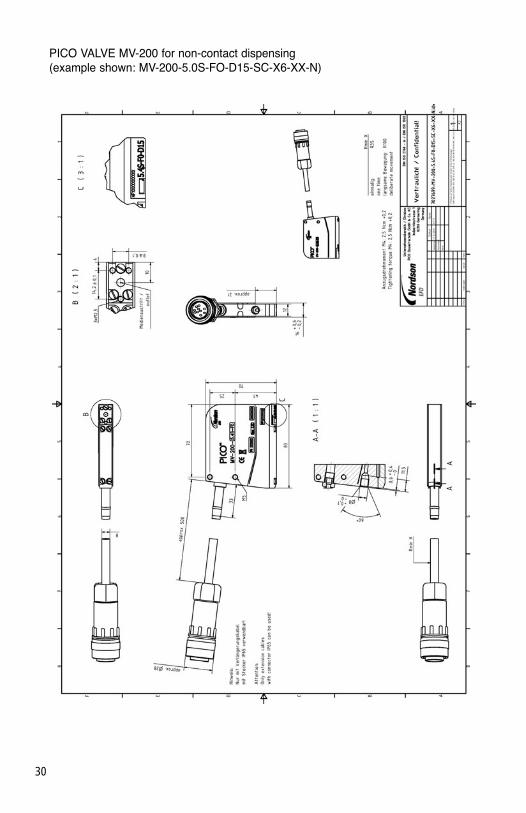
PICO VALVE MV-200 for non-contact dispensing (example shown: MV-200-5.0S-FO-D15-SC-X6-XX-N)

31
PICO VALVE CV-180 with FDA-compliant wetted materials and a 2 mm protrudingnozzle for non-contact dispensing (example shown: CV-180-5.0C-P2-D15-RC-X6-03-N)

32
A.2 Drawing
Data compiled using various fluids
Fluid Viscosity[mPas]
Pressure[MPa]
Cycle time[µs]
Distance to the substrate[mm]
Valvetemperature[°C]
Dispensingvolume [µl]
Motor oil SAE 10W-40 0.1 250 10 50 0.070
1-part acrylicUVB-hardened
165,000thixotropic
2.5 250 7 40 0.030
1-part siliconeheat-hardened
750 1 260 10 30 0.004
1-part epoxy resin
4,000 4.2 250 13 30 0.100
1-part epoxy resin
36,000thixotropic
4.6 250 11 45 0.060
1-part acrylicpaint dispersion-based
50 0.5 250 6 30 0.002
1-part acrylicUVB-hardened
80 0.6 260 11 30 0.002
1-part acrylicheat-hardened
8,000 3 250 4 30 0.006

33
Characteristics f(t); f(p)

34
For Nordson EFD LLC sales and service in over 30 countries, contact Nordson EFD or go towww.nordsonefd.com
East Providence, RI USAUSA & Canada: 800-556-3484 [email protected]
Dunstable, Bedfordshire, UK0800 585733; +44 (0) 1582 666334Ireland 00800 8272 [email protected]
Germering, Germany +49 (89) 8493 6660 [email protected]
China: +86 (21) 3866 [email protected]
Singapore: +65 6796 [email protected]
The Wave Design is a trademark of Nordson Corporation.©2012 Nordson Corporation 7015892 v030412
This equipment is regulated by the EuropeanUnion under WEEE Directive (2002/96/EC). Seewww.nordsonefd.com for information about howto properly dispose of this equipment.
NORDSON EFD ONE YEAR LIMITED WARRANTYNordson EFD PICO products are warranted for one year from date of purchase to be free from defects inmaterial and workmanship (but not against damage caused by misuse, abrasion, corrosion, negligence,accident, faulty installation or by dispensing material incompatible with equipment) when the equipmentis installed and operated in accordance with factory recommendations and instructions. Nordson EFD willrepair or replace free of charge any part of the equipment thus found to be defective, on authorized returnof the part prepaid to our factory during the warranty period. In no event shall any liability or obligation ofNordson EFD arising from this warranty exceed the purchase price of the equipment. This warranty is validonly when oil-free, clean, dry, filtered air is used.
Nordson EFD makes no warranty of merchantability or fitness for a particular purpose. In no event shallNordson EFD be liable for incidental or consequential damages.