
PICO HAND AUGER
34
PICO 3-inch and 4-inch Hand Auger - Operations and Maintenance Manual Document #: 8507-0009 Version: 3.0 PICO HAND AUGER Operations and Maintenance Manual October 7, 2019 U.S. Ice Drilling Program University of Wisconsin-Madison Space Science & Engineering Center All Rights Reserved.
Transcript of PICO HAND AUGER

PICO 3-inch and 4-inch Hand Auger - Operations and Maintenance Manual
Document #: 8507-0009 Version: 3.0
PICO HAND AUGER Operations and Maintenance Manual
October 7, 2019
U.S. Ice Drilling Program
University of Wisconsin-Madison Space Science & Engineering Center All Rights Reserved.

PICO 3-inch and 4-inch Hand Auger - Operations and Maintenance Manual
Document #: 8507-0009 Version: 3.0
TABLE OF CONTENTS:
1.0 PURPOSE ........................................................................................................................................................... 1
2.0 SCOPE ................................................................................................................................................................ 1
3.0 REFERENCES ................................................................................................................................................... 1
4.0 DEFINITIONS ................................................................................................................................................... 1
5.0 RESPONSIBILITIES ........................................................................................................................................ 2
6.0 OPERATORS MANUAL .................................................................................................................................. 2
6.1 Introduction ..................................................................................................................................................... 2
6.2 Inspection ........................................................................................................................................................ 2
6.3 Assembly ......................................................................................................................................................... 3
6.4 Operation ....................................................................................................................................................... 10
6.4.1 Introduction.......................................................................................................................................... 10
6.4.2 Drill Site Preparation ........................................................................................................................... 10
6.4.3 Taking the First Core Sample .............................................................................................................. 11
6.4.4 Taking the Second Core Sample .......................................................................................................... 12
6.4.5 Breaking The Drill String .................................................................................................................... 12
6.5 Disassembly and Packing .............................................................................................................................. 13
Appendix A: Field Maintenance ............................................................................................................................... 14
Appendix B: Sharpening Cutters ............................................................................................................................. 21
Appendix C: Penetration Screw Adjustment .......................................................................................................... 22
Appendix D: Special Drilling Conditions ................................................................................................................ 25
Appendix E: Problem Solving .................................................................................................................................. 27
Appendix F: Inspection Procedures and Forms ..................................................................................................... 28
Appendix G: Quick Guide ........................................................................................................................................ 32

PICO 3-inch and 4-inch Hand Auger - Operations and Maintenance Manual Page 1 of 32
Document #: 8507-0009 Version: 3.0
1.0 PURPOSE The objective of this document is to provide the operator a working knowledge of how the drill is assembled, tuned and operated under a variety of conditions. Step-by-step instructions are included for those with no experience with hand coring drills. Those who have experience are encouraged to scan the Tips, Notes, Cautions and Warnings. The appendices section may be useful should problems arise, or unique ice conditions be encountered.
2.0 SCOPE 2.1 This document applies to the:
2.1.1 PICO 3-inch hand auger coring drill.
2.1.2 PICO 4-inch hand auger coring drill.
3.0 REFERENCES 3.1 1008-0002 SSEC Document Control Procedure
3.2 1008-0004 SSEC Change Control Procedure
3.3 8501-0001 SSEC Project List 3.4 8501-0002 IDP Field Project Support Procedure
3.5 8507-0010 Sidewinder Power Unit Operations and Maintenance Manual
4.0 DEFINITIONS 4.1 ECN – Engineering Change Notice. 4.2 Event – Any project requiring IDP support. 4.3 Firn – The porous snow more than one year old. Its transition to ice is dependent
on pressure, time and temperature. The firn/ice transition in cold ice is usually from 60-120m deep, and is where the pores close off to form air bubbles.
4.4 IDP – U.S. Ice Drilling Program, formerly IDDO/ICDS 4.5 Drill Engineer – The IDP Engineer assigned responsibility for repair and
maintenance of the drill system. 4.6 IDP Staff – Any individual employed under the IDP contract. 4.7 Insert – The replaceable piece of the cutter assembly that does the cutting. 4.8 NSF – National Science Foundation. 4.9 Operator – Any person involved in the assembly and use of the drills described
in this document. 4.10 Penetration – The rate at which the drill advances into the hole (mm/revolution). 4.11 PICO – Polar Ice Coring Office, IDP’s predecessor. 4.12 Principal Investigator – The researcher responsible for the science project. 4.13 SideWinder – A motorized accessory package for the PICO and SIPRE hand
augers. It provides power for rotating as well as lifting and lowering the drill string.
4.14 UW-SSEC – University of Wisconsin-Space Science & Engineering Center.

PICO 3-inch and 4-inch Hand Auger - Operations and Maintenance Manual Page 2 of 32
Document #: 8507-0009 Version: 3.0
5.0 RESPONSIBILITIES 5.1 IDP Management is responsible for ensuring that IDP operators are provided
with accurate, up-to-date operator procedures.
5.2 IDP Engineering is responsible for the creation and maintenance of this manual.
5.3 Operators are responsible for ensuring these procedures are followed and any safety warnings contained herein are heeded.
5.4 SSEC QAS is responsible for ensuring that the proper procedures of document creation, review, approval, maintenance and updating are followed.
6.0 OPERATORS MANUAL 6.1 Introduction
6.1.1 The PICO hand auger drill system is a small lightweight, portable drill system. It is designed primarily to take cores from firn ice, but has been successful taking cores from many kinds of solid ice.
6.1.2 The PICO hand auger will take cores 3-inches or 4-inches in diameter depending on which PICO system you have chosen.
6.1.3 The PICO hand auger produces a roughly ½-meter long core sample (1-meter long if the optional 2-meter core barrel is used).
6.1.4 The basic PICO hand auger kit contains everything needed to take core to a depth of 6-meters.
6.1.5 The optional 2-meter core barrel package also contains enough extensions to take core to a depth of 20 meters.
6.1.6 Additional extensions will be provided on request for deeper coring requirements.
6.1.7 The PICO hand auger may be hand or power driven. If power is desired, request the Sidewinder power kit.
6.2 Inspection 6.2.1 If possible, before leaving for the field, inspect the PICO hand auger to
make sure all the parts, tools and spares are there and in good condition. An inspection form (appendix F) will be included in the kit to assist you in this inspection.
6.2.2 Using the inspection form as a guide, make sure the drill is complete and in good condition.
Note: Contact IDP if the drill is incomplete or in poor condition. 6.2.3 It is also a good idea to assemble the drill in order to familiarize yourself
with the assembly and function of the parts.

PICO 3-inch and 4-inch Hand Auger - Operations and Maintenance Manual Page 3 of 32
Document #: 8507-0009 Version: 3.0
6.3 Assembly CAUTION! THE CUTTERS AND CORE DOGS ARE SHARP. THE USE OF GLOVES IS RECOMMENDED.
6.3.1 Open the 1-meter long bag and remove the following items: 6.3.1.1 The core barrel (Item 1, Figure 1) (core head (Item 2, Figure 1)
attached).
6.3.1.2 The drive adapter with adapter pin (½ inch diameter X 3-1/2 inch or 4-1/2 inch long) (Item 3, Figure 1).
6.3.1.3 The short (14-inches to 18-inches) extension (Item 5, Figure 1).
6.3.1.4 The “T” handle (Item 6, Figure 1) The Tool Bag (Small red or blue bag).
6.3.2 Assemble the drive adapter to the core barrel :
TIP! Keep the protective cover on the core head while assembling the PICO hand auger. This will protect the cutters and minimize the chance of injuries.
6.3.2.1 Remove the adapter pin from the drive adapter. 6.3.2.2 Place the drive adapter into the end of the core barrel (Figure 2).
Align the hole in the core barrel with the hole in the adapter and replace the adapter pin.
Figure 1: PICO Hand Auger Assembly Parts
!

PICO 3-inch and 4-inch Hand Auger - Operations and Maintenance Manual Page 4 of 32
Document #: 8507-0009 Version: 3.0
Figure 2: Drive Adapter Installation
6.3.3 Assemble and Attach the “T” Handle:
6.3.3.1 Remove the bolt from the center fitting of the “T” handle. 6.3.3.2 Insert the un-reinforced fiberglass end of the short extension into
the center fitting of the “T” handle (see Figure 3). Align the hole in the short extension with the hole in the “T” handle center fitting, and replace the bolt.
Figure 3: Assembled “T” Handle

PICO 3-inch and 4-inch Hand Auger - Operations and Maintenance Manual Page 5 of 32
Document #: 8507-0009 Version: 3.0
6.3.3.3 Open the tool bag and remove 1 each drive adapter bolt (1/2-13 X 3-1/2 inch long with Nylock® nut).
6.3.3.4 Slide the aluminum-reinforced end of the short extension over the end of the drive adapter (see Figure 4).
Figure 4: Assemble “T” Handle and Core barrel
6.3.3.5 Align the hole in the drive adapter with the hole in the short
extension. 6.3.3.6 Insert the drive adapter bolt into the hole. 6.3.3.7 Using an Allen wrench and adjustable wrench (provided in the tool
bag) screw the Nylock® nut onto the drive adapter bolt.
Note: It is not necessary to completely tighten the Nylock® nut. Leave about 2mm of slop. Note: As you drill deeper into the ice you will need to add extensions to the drill.
PICO 3-inch and 4-inch Hand Auger - Operations and Maintenance Manual Page 6 of 32
Document #: 8507-0009 Version: 3.0
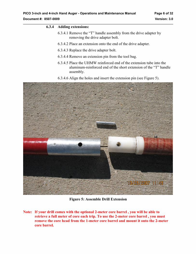
6.3.4 Adding extensions: 6.3.4.1 Remove the “T” handle assembly from the drive adapter by
removing the drive adapter bolt. 6.3.4.2 Place an extension onto the end of the drive adapter. 6.3.4.3 Replace the drive adapter bolt. 6.3.4.4 Remove an extension pin from the tool bag. 6.3.4.5 Place the UHMW reinforced end of the extension tube into the
aluminum-reinforced end of the short extension of the “T” handle assembly.
6.3.4.6 Align the holes and insert the extension pin (see Figure 5).
Figure 5: Assemble Drill Extension
Note: If your drill comes with the optional 2-meter core barrel , you will be able to
retrieve a full meter of core each trip. To use the 2-meter core barrel , you must remove the core head from the 1-meter core barrel and mount it onto the 2-meter core barrel.

PICO 3-inch and 4-inch Hand Auger - Operations and Maintenance Manual Page 7 of 32
Document #: 8507-0009 Version: 3.0
6.3.5 Removing the core head from the core barrel : 6.3.5.1 Tools needed for removing the core head:
6.3.5.1.1 3/16 inch Allen wrench 6.3.5.1.2 Dead blow mallet
6.3.5.2 Using the 3/16 inch Allen wrench, loosen (but do not remove) the four dog point set screws until they are clear of the core barrel (Figure 6).
Figure 6: Loosening the Dog Point Set Screws
6.3.5.3 Using the dead blow mallet, tap the core head free from the core
barrel. If the drill is warm, you may be able to simply pull the core head off by hand.
6.3.6 Mounting the core head to the core barrel : 6.3.6.1 Tools needed for mounting the core head:
6.3.6.1.1 3/16 inch Allen wrench 6.3.6.1.2 Dead blow mallet

PICO 3-inch and 4-inch Hand Auger - Operations and Maintenance Manual Page 8 of 32
Document #: 8507-0009 Version: 3.0
6.3.6.2 Carefully align the core head to the core barrel so the core dogs line up with the notches cut in the end of the core barrel (Figure 7, Figure 8 & Figure 9).
6.3.6.3 Carefully slide the core head onto the core barrel.
Figure 7: Alignment of the Core Dogs with the Core Dog Slots in the Core Barrel
6.3.6.4 Using the dead blow mallet, tap the core head so the four dog point
set screws are in alignment with the four holes in the core barrel. Using the 3/16 inch Allen wrench, tighten the dog point set screws until the ends of the set screws are just flush with the inside surface of the core barrel (see Figure 9).

PICO 3-inch and 4-inch Hand Auger - Operations and Maintenance Manual Page 9 of 32
Document #: 8507-0009 Version: 3.0
WARNING! BE CERTAIN ALL FOUR DOG POINT SET SCREWS PASS THROUGH THE HOLES IN THE CORE BARREL. IF THE DOG POINT SET SCREWS ARE NOT ENGAGED IN THE CORE BARREL HOLES, YOU RUN THE RISK OF LEAVING THE CORE HEAD AT THE BOTTOM OF THE HOLE.
WARNING! DO NOT OVER TIGHTEN THE DOG POINT SET SCREWS. THIS WILL DEFLECT THE FIBERGLASS BARREL WALL AND WEAKEN THE MATERIAL SURROUNDING THE HOLES.
Figure 8: Assembly of the Core Head And The Core Barrel
!
!

PICO 3-inch and 4-inch Hand Auger - Operations and Maintenance Manual Page 10 of 32
Document #: 8507-0009 Version: 3.0
Figure 9: Final Position of the Dog Point Set Screws
6.4 Operation 6.4.1 Introduction
The PICO hand auger was designed to take core samples from firn ice. Therefore, the operation instructions in this section describe how one would take core samples from firn ice. The PICO hand auger will also take core samples from many other ice types. Refer to Appendix B Special Drilling Conditions for tips on drilling other ice types.
6.4.2 Drill Site Preparation 6.4.2.1 It is best to drill on a level surface. It is easier to move around the
drill, and it is less likely the hole will become contaminated by material that slides or rolls down the slope into the hole.
6.4.2.2 When drilling on a sloped surface, consider cutting a shelf into the slope large enough for the drilling operation. Place barriers uphill from the drill site to minimize the chance of contamination.
6.4.2.3 Set up your core handling area away from, but convenient to the drill site.

PICO 3-inch and 4-inch Hand Auger - Operations and Maintenance Manual Page 11 of 32
Document #: 8507-0009 Version: 3.0
6.4.2.4 If possible, erect tarps to shade the core handling area. This is to prevent the sun from heating up the drill, and melting the core samples.
6.4.2.5 Keep insulated core boxes close at hand for safe storage of the core. Consider burying filled core boxes in the snow for extra protection. If core boxes are not available, bagged core samples can be buried in the snow for safekeeping until core boxes arrive.
6.4.3 Taking the First Core Sample 6.4.3.1 Remove the casing (Item 7, Figure 1) from the kit, and pound it
into the surface with the dead blow mallet. Leave about 6-inches above the surface to minimize the chance of hole contamination. The casing also stabilizes the top of the hole and prevents crumbling around the hole.
WARNING! BE CAREFUL NOT TO DROP ANYTHING DOWN THE HOLE! THIS CAN CONTAMINATE THE SAMPLES, AND MAY DAMAGE THE CUTTING EDGES OF THE DRILL.
6.4.3.2 Scoop the snow out of the casing.
6.4.3.3 Remove the protective boot from the core head.
6.4.3.4 Place the core head end of the drill inside the casing centering it as well as possible.
6.4.3.5 Turn the drill clockwise, while applying slight downward pressure on the drill. Continue until the top of the core barrel is approximately 6-inches above the surface (even with the top of the casing.
TIP! When taking the first sample, have someone standing off to your right or left to verify you are not leaning the drill toward or away from you.
TIP! When first starting a hole, it may be easier to keep the drill stable by turning the core barrel with your hands on the barrel. Once the drill is about a foot or so in, use the “T” handle
6.4.3.6 Stop turning the drill, and grasp the “T” handle with both hands. Give the “T” handle a sharp jerk upward to break the core sample free from the bottom of the hole.
6.4.3.7 Remove the drill from the hole.
6.4.3.8 Remove the drive adapter pin.
6.4.3.9 Remove the drive adapter from the core barrel.
6.4.3.10 Carry the core barrel to the core handling area. 6.4.3.11 Push the core sample (from the head end of the core barrel) out
of the core barrel using a core pusher.
!

PICO 3-inch and 4-inch Hand Auger - Operations and Maintenance Manual Page 12 of 32
Document #: 8507-0009 Version: 3.0
6.4.3.12 The core must be supported by a core tray. There are many designs in use. You may have a preference for one type or another. Most find a piece of PVC sewer pipe cut in half lengthwise works well.
6.4.4 Taking the Second Core Sample TIP! Clean the snow and ice off the core dogs, and make sure they swing freely. Ice and
snow may pack into the core dog windows. This will cause the core dogs to perform poorly.
6.4.4.1 Remove the “T” handle assembly from the drive adapter. 6.4.4.2 Add an extension (Item 4, Figure 1) to the drive adapter and
replace the “T” handle assembly. 6.4.4.3 Attach the core barrel to the drive adapter. 6.4.4.4 Place the core barrel into the hole and turn clockwise until the core
barrel is full.
CAUTION! DO NOT OVER DRILL! IF YOU SEE ICE CHIPS PILING UP ON TOP OF THE DRIVE ADAPTER , YOU ARE OVER DRILLING. THIS MAY CAUSE THE DRILL TO BECOME STUCK IN THE HOLE. IF THE DRILL BECOMES STUCK, REFER TO APPENDIX C PROBLEM SOLVING.
Note: The first sample should be about 1-meter long. The chips that were in the flights of the core barrel when the first sample was removed fall to the bottom of the hole. When the second core sample is taken you must first drill through these chips. The core barrel will be partially filled with these chips, which leaves less room for core. Also, while drilling the second core, chips travel up the flights and fall into the core barrel on top of the core sample. For these reasons, you will only get about ½ meter core the second trip (and all subsequent trips) down the hole.
Note: If your drill kit has the optional 2-meter core barrel , now would be the time to remove the core head from the 1-meter barrel, and mount it on the 2-meter barrel. The 2-meter core barrel will collect about 1-meter long core samples.
6.4.4.5 Break the core free from the bottom of the hole and deliver it to the core handling area.
6.4.4.6 Continue adding extensions as you get deeper.
Note: Once you have reached a depth of about 5 meters, you will find the drill string is getting a bit unwieldy. At this point, you will need to break the string, in order to take the drill out of the hole in more manageable sections.
6.4.5 Breaking The Drill String 6.4.5.1 Pull the drill string out of the hole so only a manageable number of
extensions are clear of the hole. 6.4.5.2 Place the extension clamp (Figure 10) onto the string just below
the point the string will be broken. 6.4.5.3 Lower the drill string until the extension clamp rests on the casing. 6.4.5.4 Remove the drill string above the extension clamp.
!

PICO 3-inch and 4-inch Hand Auger - Operations and Maintenance Manual Page 13 of 32
Document #: 8507-0009 Version: 3.0
6.4.5.5 Remove the “T” handle and attach it to the drill string remaining in the hole.
6.4.5.6 While supporting the weight of the drill by the “T” handle , remove the extension clamp.
Figure 10: The extension clamp.
Note: It is not necessary to remove the extension clamp if you do not intend to break the string again.
WARNING! NEVER BREAK THE STRING WITHOUT USING THE EXTENSION CLAMP! NEVER REMOVE THE EXTENSION CLAMP UNLESS THE “T” HANDLE IS ATTACHED! IF THE DRILL STRING SLIPS OUT OF YOUR HANDS, IT WILL FALL DOWN THE HOLE.
6.5 Disassembly and Packing 6.5.1 Disassembly of the drill is done in the reverse order it was assembled. 6.5.2 It is not necessary to remove the core head from the 2-meter core barrel
and remount it on the 1-meter core barrel. 6.5.3 Be sure the protective boot is firmly attached on the core head. 6.5.4 Before putting the parts back into the bag, remove as much snow as you
can. 6.5.5 Use the inspection form (Appendix F) to make sure everything gets back
into the kit. 6.5.6 Use the inspection form to note any missing or damaged items. 6.5.7 Once everything is back in the kit, tighten the black webbing straps as
tightly as you can.
!

PICO 3-inch and 4-inch Hand Auger - Operations and Maintenance Manual Page 14 of 32
Document #: 8507-0009 Version: 3.0
Appendix A: Field Maintenance 1.0 Cutters
1.1 Removing Cutters: 1.1.1 Tools required to remove the cutters:
1.1.1.1 3/16-inch Allen wrench 1.1.1.2 Vice Grip Pliers 1.1.1.3 Dead Blow Mallet
1.1.2 Using the 3/16-inch Allen wrench, remove the ¼-20 flat head cutter binding screw (Figure A.1).
Figure A.1: Removing the cutter screws
1.1.3 Grip the cutter with the vice grip pliers, and pull the cutter off (it may help
to lightly tap the vice grip with the dead blow mallet while pulling) (Figure A.2).
1.1.4 The alignment pins may cling to the core head, or to the cutter. If they cling to the cutter, remove them using the vice grip, and tap them into the core head.

PICO 3-inch and 4-inch Hand Auger - Operations and Maintenance Manual Page 15 of 32
Document #: 8507-0009 Version: 3.0
Figure A.2: Removing the cutter.
1.2 Installing the cutters: 1.2.1 Tools required to install the cutters:
1.2.1.1 3/16-inch Allen wrench 1.2.1.2 Dead blow mallet
1.2.2 Align the cutters with the alignment pins on the core head. 1.2.3 Tap the cutter down into the cutter pocket using the dead blow mallet. 1.2.4 Install the flat head ¼-20 cutter binding screw and tighten it with the 3/16-
inch Allen wrench.
1.3 Inserted Cutters: 1.3.1 The PICO hand augers now come equipped with inserted cutters. 1.3.2 The PICO hand auger will be set up with inserted cutters when you
receive it. 1.3.3 If you choose to use the non-inserted cutters, follow the instructions in
Appendix A: 1.1 and 1.2 to remove the inserted cutters and install the non-inserted cutters.
1.3.4 The inserted cutters are an assembly of three parts (Figure A.3).
1.3.4.1 Part A: Insert Holder

PICO 3-inch and 4-inch Hand Auger - Operations and Maintenance Manual Page 16 of 32
Document #: 8507-0009 Version: 3.0
1.3.4.2 Part B: Insert 1.3.4.3 Part C: Insert screw
Figure A.3: Inserted Cutter Parts
1.3.5 The inserts can be replaced without removing the insert holders from the core head.
1.3.5.1 Removing the inserts: 1.3.5.1.1 Using a 5/64 inch Allen wrench, loosen and remove the
insert screw (Figure A.3, Part C and Figure A.4). 1.3.5.1.2 Remove the insert (Figure A.3, Part B) from the insert
holder (Figure A.3, Part A) 1.3.5.1.3 Repeat Steps 1.3.5.1.1 and 1.3.5.1.2 for both cutters.
1.3.5.2 Replacing the inserts: 1.3.5.2.1 Insert a new insert (Figure A.3, Part B) into the insert
holder (Figure A.3, Part A). 1.3.5.2.2 Using a 5/64 inch Allen wrench, replace and tighten the
insert screw (Figure A.3, Part C). 1.3.5.2.3 Repeat steps 1.3.5.2.1 and 1.3.5.2.2 for both cutters.

PICO 3-inch and 4-inch Hand Auger - Operations and Maintenance Manual Page 17 of 32
Document #: 8507-0009 Version: 3.0
Figure A.4: Removing and replacing the insert screw.
1.4 Core Dogs: Note: The configuration of the coring head is such that one should be able to capture the
core WITHOUT core dogs; therefore, one might try using core dogs only after failed attempts to catch the core.
1.4.1 Removing core dogs 1.4.1.1 Tools required:
1.4.1.1.1 Allen wrench 1.4.1.1.2 Needle nosed pliers
1.4.1.2 Using an Allen wrench, loosen the core dog set screw. 1.4.1.3 Using a needle nose pliers, pull the core dog pin out (see Figure
A.5).

PICO 3-inch and 4-inch Hand Auger - Operations and Maintenance Manual Page 18 of 32
Document #: 8507-0009 Version: 3.0
Figure A.5: Removing the Core Dogs
1.4.1.4 Remove the core dog and core dog spring.
1.4.2 Installing core dogs 1.4.2.1 Tools required:
1.4.2.1.1 Allen wrench 1.4.2.1.2 Needle nose pliers 1.4.2.1.3 Side cutting wire cutters
1.4.2.2 Insert the core dog pin partway into its hole in the core head. 1.4.2.3 Insert the core dog into the core dog window and slide the core
dog pin part way into the core dog. 1.4.2.4 Press the core dog spring into the slot in the core dog, and push
the core dog pin the rest of the way into its hole. The pin should pass through the coil of the core dog spring.
Note: It is best to use a new core dog spring each time the core dogs are replaced. 1.4.2.5 Using the Allen wrench, tighten the core dog set screw. 1.4.2.6 Bend the end of the core dog spring that is resting on the core
dog back against the core dog (see Figure A.6)

PICO 3-inch and 4-inch Hand Auger - Operations and Maintenance Manual Page 19 of 32
Document #: 8507-0009 Version: 3.0
Figure A.6: Core Dog Spring Bend
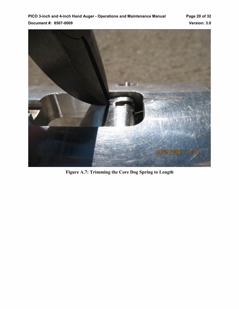
1.4.2.7 Using the side cutting wire cutters, snip off the long ends of the
core dog spring (see Figure A.7).
PICO 3-inch and 4-inch Hand Auger - Operations and Maintenance Manual Page 20 of 32
Document #: 8507-0009 Version: 3.0
Figure A.7: Trimming the Core Dog Spring to Length

PICO 3-inch and 4-inch Hand Auger - Operations and Maintenance Manual Page 21 of 32
Document #: 8507-0009 Version: 3.0
Appendix B: Sharpening Cutters 1.0 The short answer to how to sharpen the cutters is to not do it in the field. If you expect
dirty, sandy or rocky ice, request carbide inserted cutters, and plenty of spares. In clean ice/firn, the standard kit spares should suffice. If you must sharpen cutters in the field, read on.
2.0 Tools Required: Diamond hone
3.0 The cutting edge of the cutter is made up of two intersecting angles. The rake angle (see Figure B.1) may vary from 30º to 45º. The relief angle (see Figure B.1) may vary from 10º to 15º. When sharpening the cutters, care should be taken to avoid changing either of these angles, particularly the relief angle. Changing the relief angle will adversely affect the penetration rate of the drill.
Figure B.1: Rake and Relief Angles
4.0 It is also very important that all cutters are sharpened equally. If one is sharpened more than the other(s), the high cutter will do all the cutting. Also, it may cause the drill to wobble in the hole. This may adversely affect core quality.
5.0 Place the diamond hone on a firm level surface. 6.0 Place the rake angle surface flat on the diamond hone and slide it along the hone’s length.
Slight pressure will be required. At the end of the stroke, repeat the process. Count the number of strokes, and repeat them on the other cutter(s).
7.0 Turn the cutter over and place the relief surface flat on the diamond hone. To do this you will have to hang the tail of the cutter over the edge of the hone. Repeat the process described in Appendix B, Paragraph 6.0.
8.0 Repeat this process until all nicks are removed and the cutter is razor sharp.

PICO 3-inch and 4-inch Hand Auger - Operations and Maintenance Manual Page 22 of 32
Document #: 8507-0009 Version: 3.0
Appendix C: Penetration Screw Adjustment 1.0 Tools required:
1.1 3/16 inch Allen wrench 1.2 Dial caliper
2.0 Using the dial caliper, measure the distance between the cutting edge of the cutter, and the base of the core head. Do this for both cutters (see Figure C.1).
Note: There should be no more than 0.005 inches difference between cutters. If there is a difference greater than 0.005 inches, check to make sure the cutters are seated properly in the cutter pocket. If not, remove the cutter and clean the mating surfaces. Reinstall the cutter. If the cutters are seated well, and there is still more than a 0.005 inch difference, replace the cutters.
Figure C.1: Measuring Cutter Height

PICO 3-inch and 4-inch Hand Auger - Operations and Maintenance Manual Page 23 of 32
Document #: 8507-0009 Version: 3.0
Figure C.2: Measuring the Penetration Screw Height
3.0 The difference between the height of the cutting edges and the penetration screws may
vary between 0.025 inches to 0.060 inches depending on the drilling conditions (see appendix B). Once you know what difference is required for your drilling conditions, subtract that amount from the distance measured in Appendix C, paragraph 2. The height of the penetration screws may be measured from the base of the core head (see Figure C.2).
4.0 Using the 3/16 Allen wrench, adjust the penetration screw in or out to achieve the desired height (Figure C.3)
Tip: One full turn of the penetration screw will raise (or lower) the screw 0.050 inches.

PICO 3-inch and 4-inch Hand Auger - Operations and Maintenance Manual Page 24 of 32
Document #: 8507-0009 Version: 3.0
Figure C.3: Adjusting the height of the Penetration Screws

PICO 3-inch and 4-inch Hand Auger - Operations and Maintenance Manual Page 25 of 32
Document #: 8507-0009 Version: 3.0
Appendix D: Special Drilling Conditions 1.0 Firn
1.1 Firn is the easiest ice to core. The surface will probably be harder, with softer ice underneath. Normally core dogs are not required to break the core when drilling firn. In fact, you may want to remove the core dogs to prevent them from damaging the surface of the core. In very soft ice, the core dogs can actually mill the core down as you drill. If this happens, definitely remove the core dogs.
1.2 The penetration screws do not have enough surface area to have much effect in firn. Therefore, it’s safe to ignore penetration screw adjustments.
2.0 Solid Ice which includes: 2.1 Blue Ice is ice that is formed at depth but comes up as the glacier moves to an
area where sublimation occurs, such as near an exposed land mass that absorbs sunlight and warms the air. The sublimation removes the upper layers of firn and snow and ice over time exposing the ice. It will probably have a near uniform temperature profile in its upper few meters and should be straightforward to core with a hand corer. It may have some residual stresses from its movement and so may be a bit brittle.
2.2 Lake Ice can be multiple years in age and many meters thick or just annual ice only a few centimeters thick. If it is near exposed land, it may have dirt and dust in layers or throughout. Its surface may have a different temperature than its solid/liquid interface. It also may have snow accumulated on its surface. Any embedded dirt/dust will dull the cutters and slow drilling but don’t give up. NOTE: You will almost certainly get stuck with a hand corer if the ice temperature reaches 0°C (snowball packing temperature).
2.3 Sea Ice is ice that forms on the surface of salt water. The ice contains varying degrees of salinity, and may contain pockets of liquid salt water. The freezing temperature of salt water is lower than that of fresh water, and varies with the level of salinity.
3.0 Ice with Dirt, Sand or very small Rocks 3.1 Penetration screw adjustment will be based more on what kind of ice it would be
without the dirt and/or sand. However, in ice with dirt, sand and rock, the height of the penetration screws may change as they wear down. Check them occasionally and make adjustments as needed.
3.2 Whether or not core dogs are required also depends upon what kind of ice it would be without the sand. Core dogs will wear rapidly in ice with dirt, sand or rock and may require frequent replacement. Dirt and sand can build up in the spaces around the core dogs and prevent them from moving freely. Clean them after each trip down the hole.
Note: Request carbide cutters, and plenty of spares. 4.0 Rocky ice
Success drilling in ice embedded with rocks has mostly been achieved with powered rotation and a controlled feed rate, using carbide cutters. If you hit a rock, ease up on the downward force you are applying to the drill. Lightly scrape away at the rock until

PICO 3-inch and 4-inch Hand Auger - Operations and Maintenance Manual Page 26 of 32
Document #: 8507-0009 Version: 3.0
through. Continue drilling for a few cm, and pull up the drill. Examine the core. If the core quality is good below the rock, return to drilling. If not, replace the cutters/inserts.
Note: Request carbide cutters, and plenty of spares. 5.0 Temperate Ice/Snow
Core drilling in temperate ice (ice that is at or very near 0°C) should NOT be attempted with the PICO hand augers. The chips will pack to form near solid ice around the auger flights and coring head and will become so stuck that one will have to dig the drill out or abandon it. Only drills with both inner and outer core barrels may be considered for core drilling temperate ice and snow.

PICO 3-inch and 4-inch Hand Auger - Operations and Maintenance Manual Page 27 of 32
Document #: 8507-0009 Version: 3.0
Appendix E: Problem Solving 1.0 Stuck drill
1.1 Try turning the drill backwards while pulling up on the “T” handle. If the flights are packed with snow, you may be able to screw it out.
1.2 Pour 1 or 2 liters of alcohol down the hole. Let it sit for two or three hours and try removing the drill. Do not use alcohol mixes less than 25%.
1.3 If all else fails, start digging.
2.0 Item Dropped Down The Hole 2.1 This is a tricky one. It depends on what is down the hole. If its magnetic, try
fishing it out with a magnet. If its small and non-magnetic, try to carefully drill beyond it and bring it up with the chips. This may damage the cutters so be prepared to replace them. If you have a generator and a shop vacuum, you can try to vacuum it out.
2.2 If a core barrel has been dropped down the hole, try fishing it out with a wire hook on the end of some parachute or “P” cord. If you can hook one of the chip holes, you should be able to pull it out. If you have a couple of bungee cords, hook one end in the holes at the bottom of the extension tubes (remove the core barrel adapter first). Trip the extension tube string down the hole. Wiggle it around a bit and see if you can hook the core barrel on the bungee cords.
2.3 If there are extension tubes attached to the core barrel. Try this: 2.3.1 Assemble enough extension tubes to reach the down hole drill string. 2.3.2 Trip the assembly down the hole and slip the bottom end over the mating
down hole extension tube. 2.3.3 Make a slip knot in the end of a length of “P” cord. 2.3.4 Loop the slip knot over the extension assembly and work it down the hole
until it is below the coupling on the uppermost dropped extension tube. 2.3.5 Pull up on the “P” cord. The slip knot should synch down and grip below
the coupling. 2.3.6 Remove the extension tube assembly from the hole (to minimize the
weight of the drill string). 2.3.7 Pull the remaining drill string out of the hole using the “P” cord.

PICO 3-inch and 4-inch Hand Auger - Operations and Maintenance Manual Page 28 of 32
Document #: 8507-0009 Version: 3.0
Appendix F: Inspection Procedures and Forms 1. Upon arrival of any parts in Madison, IDP staff will:
a. Clean, test, and store all components.
i. Track quantities through the Hand Auger Inventory spreadsheet at C:\EPDM\IDDO\Hand Augers\.
ii. Any parts that are out of spec or broken will be removed from the general inventory until they are repaired or replaced.
2. Prior to any parts leaving Madison, IDP staff will:
a. Pack the kit per the PI’s field request.
b. Fill out a Fit Checklist and an Inventory Checklist, including a paper copy in the kit.
c. Update the Hand Auger Inventory spreadsheet.
d. If sending part designs that have not been field tested, proven backup methods will be included as well.
3. Upon arrival of any parts in the field, field personnel will:
a. Verify that all components arrived undamaged.
4. Prior to any parts leaving the field, field personnel will:
a. Clean and dry all components as best as possible.
b. Use the Inventory Checklist to verify that the correct components are being returned.
IDP Staff Fit Checklist - PICO Hand Auger Season: User: Where Used: PICO Hand Auger ID #_______ Size: __________
Done? Task Fit tee handle to all extensions Fit tee handle to core barrel adapter Fit all extensions to each other Fit extension clamp to all extensions Fit all extensions to core barrel adapter Fit core barrel adapter to each barrel Fit cutter head(s) to each barrel Fit cutters and holders to cutter head(s) and install one set Fit core dogs to cutter head(s) Fit inserts to holders Install penetration shoes in cutter head(s)

PICO 3-inch and 4-inch Hand Auger - Operations and Maintenance Manual Page 29 of 32
Document #: 8507-0009 Version: 3.0
PICO 3 inch Hand Auger Inventory Checklist Season: User: Where Used: PICO 3-inch Hand Auger ID #_______ Contents of the Short Bag (including bag): Item Standard Qty Qty Packed Notes
1 Short Bag 1 Each 2 3” X 1-meter core barrel 1 Each 3 1-meter extensions 6 Each 4 3” Core Head (complete) 1 Each 5 “T” Handle (complete) 1 Each 6 3” Core Barrel Adapter 1 Each 7 Extension Clamp 1 Each 8 Tool Bag 1 Each 9 Magnet with cord 1 Each
Contents of the Tool Bag: Item Standard Qty Qty Packed Notes 10 3-13/16 long Pin 1 Each 11 Dead Blow Mallet 1 Each 12 3/16-inch Standard Screwdriver 1 Each 13 1/4-inch Standard Screwdriver 1 Each 14 SAE Allen Wrench Set 1 Each 15 Diamond Hone 1 Each 16 Duct Tape 1 Roll 17 2-13/16” Extension Pins 25 Each 18 Adjustable Wrench 1 Each 19 Dial Caliper 1 Each 20 Kevlar Gloves 1 Pair 21 PICO Hand Auger Manual 1 Each 22 Phillips Screwdriver 1 Each 23 Vice Grip 1 Each 24 Needle Nose Pliers 1 Each 25 Slip Joint Pliers 1 Each 26 Side Cutters 1 Each 27 Flat Bastard File 1 Each 28 Plano Case 1 Each
Contents of the Plano Case: Item Standard Qty Qty Packed Notes 29 Core Dogs (3 sizes) 2 Each/size 30 Core Dog Set Screws 6-32 x 1/8” 4 Each 31 Core Dog Springs 10 Each 32 Bellville Washers 10 Each 33 ¼-20 x ¾” Flat Head Cap Screws 2 Each 34 ¼-20 x ¾” Socket Head Cap Screws 2 Each 35 3/8-16 x 3/8” Dog Point Set Screws 4 Each 36 1/8” x 1-1/2” Dowel Pins 4 Each 37 1/8” x 3/4” Spring Pins 4 Each 38 3” Cutters 2 Each 39 3” Insert Holders 2 Each 40 3” Inserts 10 each 41 Insert Screws 6-40 x ¼” 10 each
Long Bag (including bag): Item Standard Qty Qty Packed Notes
42 Long Bag 1 Each 43 3” X 2-m Core Barrel 1 Each 44 2-m Extensions 6 each 45 Extendable Push Rod 1 Each 46 Casing 1 Each 47 Back Pack Harness 1 Each

PICO 3-inch and 4-inch Hand Auger - Operations and Maintenance Manual Page 30 of 32
Document #: 8507-0009 Version: 3.0
PICO 3 inch Hand Auger Inventory Checklist PICO 4 inch Hand Auger Inventory Checklist Season: User: Where Used: PICO 4-inch Hand Auger ID #_____ Contents of the Short Bag (including bag): Item Standard Qty Qty Packed Notes
1 Short Bag 1 Each 2 4” X 1-meter core barrel 1 Each 3 1-meter extensions 6 Each 4 4” Core Head (complete) 1 Each 5 “T” Handle (complete) 1 Each 6 4” Core Barrel Adapter 1 Each 7 Extension Clamp 1 Each 8 Tool Bag 1 Each 9 Magnet with cord 1 Each
Contents of the Tool Bag: Item Standard Qty Qty Packed Notes
10 4-13/16 Pin 1 Each 11 Dead Blow Mallet 1 Each 12 3/16-inch Standard Screw Driver 1 Each 13 ¼-inch Standard Screw Driver 1 Each 14 SAE Allen Wrench Set 1 Each 15 Diamond Hone 1 Each 16 Duct Tape 1 Roll 17 2-13/16” Pins 25 Each 18 Adjustable Wrench 1 Each 19 Dial Caliper 1 Each 20 Kevlar Gloves 1 Pair 21 PICO Hand Auger Manual 1 Each 22 Philips Screwdriver 1 Each 23 Vice Grip 1 Each 24 Needle Nose Pliers 1 Each 25 Slip Joint Pliers 1 Each 26 Side Cutters 1 Each 27 Flat Bastard File 1 Each 28 Plano Case 1 Each
Contents of the Plano Case: Item Standard Qty Qty Packed Notes
29 Core Dogs (3 sizes) 2 Each/ size 30 Core Dog Set Screws 6-32 x 1/8” 4 Each 31 Core Dog Springs 10 Each 32 Bellville Washers 10 Each 33 ¼-20 x 7/8 Flat Head Cap Screws 2 Each 34 ¼-20 x ¾ Socket Head Cap Screws 2 Each 35 3/8-16 x ½ Dog Point Set Screws 4 Each 36 3/16 x 1-1/4 Dowel Pins 4 Each 37 3/16 x ¾ Dowel Pins 4 Each 38 4” Cutters 2 Each 39 4” Insert Holders 2 Each 40 4” Inserts 10 Each 41 Insert Screws 6-40 x ¼” 10 Each 42 Penetration Shoes (not all kits) 2 Each/ Size
Long Bag (including bag): Item Standard Qty Qty Packed Notes
43 Long Bag 1 Each 44 4” X 2-m Core Barrel 1 Each 45 2-m Extensions 6 Each 46 Casing 1 Each 47 Extendable Push Rod 1 Each

PICO 3-inch and 4-inch Hand Auger - Operations and Maintenance Manual Page 31 of 32
Document #: 8507-0009 Version: 3.0
(This page intentionally left blank.)

PICO 3-inch and 4-inch Hand Auger - Operations and Maintenance Manual Page 32 of 32
Document #: 8507-0009 Version: 3.0
Appendix G: Quick Guide 1. Verify that the kit is complete and that all critical pieces fit together before use. 2. It is significantly easier to drill on a level surface, so if drilling on a sloped area, consider
cutting a level shelf into the snow to operate on. 3. To start drilling a vertical hole, press the starting casing firmly into the snow, place the
cutters against the surface and turn clockwise while applying slight downward pressure. It is good habit during the first meter of drilling to periodically check for plumbness with a carpenter level as the first meter determines the orientation of the entire hole.
4. Depending on the ice conditions, the hole may be able to be started by simply rotating the barrel without the T handle. If this is the case, a 2-meter barrel may be used on the first run.
5. For most ice conditions (especially firn), the use of core dogs is not beneficial as the internal taper of the head is sufficient to break and retrieve the core.
6. To drill, rotate the handle clockwise while applying minimal (ideally zero) downward pressure. As the depth increases, add extensions to the drill stem.
7. On the first run, the drill will be able to recover a full barrel of core, but on every subsequent run, it will only be able to obtain half the barrel length of core because of chips.
8. Do not over drill. Doing so will cause the chips to overflow on top of the barrel and wedge it firmly in place. Measure/mark a stop point before beginning each drill run. If there are any unexpected changes to cutting resistance, stop drilling and break the core.
9. Break the core free by giving a quick, sharp jerk upwards on the T handle. Do not gradually apply force, as this will only serve to compact the chips in the flights and stick the barrel.
10. Remove the core from the barrel by disconnecting the barrel adapter from the barrel and then sliding the core out the top of the barrel.
11. When raising or lowering the drill to depths greater than 6 meters, use the extension clamp to support the drill while breaking the stem into smaller sections (~4m). Be careful when using the clamp to pull the drill out of the hole as it can slip, slide down the stem and pinch fingers.
12. In between runs, it is a good idea to brush off and/or dry the core barrel and head as water accumulation may freeze the barrel in the hole, making it near impossible to remove.
13. Be careful when the cutter head is exposed, as the cutters are very sharp. Consider wearing gloves when dealing with the head.
14. When finished using the PICO drill, be sure to dry off all parts and remove snow/ice chunks from the bags to prevent rusting during transport and/or storage.