PIC18F87J72 Single-Phase Energy Meter Calibration User's Guide
62
© 2011 Microchip Technology Inc. DS51964A PIC18F87J72 Single-Phase Energy Meter Calibration User’s Guide
Transcript of PIC18F87J72 Single-Phase Energy Meter Calibration User's Guide

© 2011 Microchip Technology Inc. DS51964A
PIC18F87J72 Single-PhaseEnergy Meter Calibration
User’s Guide
Note the following details of the code protection feature on Microchip devices:• Microchip products meet the specification contained in their particular Microchip Data Sheet.
• Microchip believes that its family of products is one of the most secure families of its kind on the market today, when used in the intended manner and under normal conditions.
• There are dishonest and possibly illegal methods used to breach the code protection feature. All of these methods, to our knowledge, require using the Microchip products in a manner outside the operating specifications contained in Microchip’s Data Sheets. Most likely, the person doing so is engaged in theft of intellectual property.
• Microchip is willing to work with the customer who is concerned about the integrity of their code.
• Neither Microchip nor any other semiconductor manufacturer can guarantee the security of their code. Code protection does not mean that we are guaranteeing the product as “unbreakable.”
Code protection is constantly evolving. We at Microchip are committed to continuously improving the code protection features of ourproducts. Attempts to break Microchip’s code protection feature may be a violation of the Digital Millennium Copyright Act. If such actsallow unauthorized access to your software or other copyrighted work, you may have a right to sue for relief under that Act.
Information contained in this publication regarding deviceapplications and the like is provided only for your convenienceand may be superseded by updates. It is your responsibility toensure that your application meets with your specifications.MICROCHIP MAKES NO REPRESENTATIONS ORWARRANTIES OF ANY KIND WHETHER EXPRESS ORIMPLIED, WRITTEN OR ORAL, STATUTORY OROTHERWISE, RELATED TO THE INFORMATION,INCLUDING BUT NOT LIMITED TO ITS CONDITION,QUALITY, PERFORMANCE, MERCHANTABILITY ORFITNESS FOR PURPOSE. Microchip disclaims all liabilityarising from this information and its use. Use of Microchipdevices in life support and/or safety applications is entirely atthe buyer’s risk, and the buyer agrees to defend, indemnify andhold harmless Microchip from any and all damages, claims,suits, or expenses resulting from such use. No licenses areconveyed, implicitly or otherwise, under any Microchipintellectual property rights.
DS51964A-page 2
Trademarks
The Microchip name and logo, the Microchip logo, dsPIC, KEELOQ, KEELOQ logo, MPLAB, PIC, PICmicro, PICSTART, PIC32 logo, rfPIC and UNI/O are registered trademarks of Microchip Technology Incorporated in the U.S.A. and other countries.
FilterLab, Hampshire, HI-TECH C, Linear Active Thermistor, MXDEV, MXLAB, SEEVAL and The Embedded Control Solutions Company are registered trademarks of Microchip Technology Incorporated in the U.S.A.
Analog-for-the-Digital Age, Application Maestro, chipKIT, chipKIT logo, CodeGuard, dsPICDEM, dsPICDEM.net, dsPICworks, dsSPEAK, ECAN, ECONOMONITOR, FanSense, HI-TIDE, In-Circuit Serial Programming, ICSP, Mindi, MiWi, MPASM, MPLAB Certified logo, MPLIB, MPLINK, mTouch, Omniscient Code Generation, PICC, PICC-18, PICDEM, PICDEM.net, PICkit, PICtail, REAL ICE, rfLAB, Select Mode, Total Endurance, TSHARC, UniWinDriver, WiperLock and ZENA are trademarks of Microchip Technology Incorporated in the U.S.A. and other countries.
SQTP is a service mark of Microchip Technology Incorporated in the U.S.A.
All other trademarks mentioned herein are property of their respective companies.
© 2011, Microchip Technology Incorporated, Printed in the U.S.A., All Rights Reserved.
Printed on recycled paper.
ISBN: 978-1-61341-305-0
© 2011 Microchip Technology Inc.
Microchip received ISO/TS-16949:2002 certification for its worldwide headquarters, design and wafer fabrication facilities in Chandler and Tempe, Arizona; Gresham, Oregon and design centers in California and India. The Company’s quality system processes and procedures are for its PIC® MCUs and dsPIC® DSCs, KEELOQ® code hopping devices, Serial EEPROMs, microperipherals, nonvolatile memory and analog products. In addition, Microchip’s quality system for the design and manufacture of development systems is ISO 9001:2000 certified.

PIC18F87J72 SINGLE-PHASEENERGY METER CALIBRATION
USER’S GUIDE
Table of Contents
Preface ........................................................................................................................... 5Introduction............................................................................................................ 5Document Layout .................................................................................................. 5Conventions Used in this Guide ............................................................................ 6Recommended Reading........................................................................................ 7The Microchip Web Site ........................................................................................ 7Customer Support ................................................................................................. 7Document Revision History ................................................................................... 8
Chapter 1. Product Overview1.1 Introduction ..................................................................................................... 9
Chapter 2. Meter Calibration2.1 Introduction ................................................................................................... 112.2 Types of Calibration ..................................................................................... 112.3 Closed Loop Calibration ............................................................................... 122.4 Multipoint Calibration .................................................................................... 302.5 Single Point Calibration ................................................................................ 482.6 Creep Threshold Calibration ........................................................................ 492.7 Meter Specifications And Calibration Parameters ........................................ 51
Chapter 3. Microchip Energy Meter Software3.1 Introduction ................................................................................................... 533.2 Main Screen ................................................................................................. 533.3 Debug Mode ................................................................................................. 56
Chapter 4. Communication Protocol4.1 Protocol ........................................................................................................ 59
Worldwide Sales and Service .................................................................................... 62
© 2011 Microchip Technology Inc. DS51964A-page 3

© 2011 Microchip Technology Inc. DS51964A-page 4

PIC18F87J72 SINGLE-PHASEENERGY METER CALIBRATION
USER’S GUIDE
Preface
INTRODUCTIONThis chapter contains general information that will be useful to know before using the Microchip Single-Phase Energy Meter Calibration Tool. Items discussed in this chapter include:• Document Layout• Conventions Used in this Guide• Recommended Reading• The Microchip Web Site• Customer Support• Document Revision History
DOCUMENT LAYOUT This document describes how to use the Single Phase Energy Meter Calibration toolin energy meter design. The manual layout is as follows: • Chapter 1. Product Overview provides a brief overview of the calibration tool, its
features and uses.• Chapter 2. Meter Calibration provides detail on calibration implementation and
how to calibrate the meter. The PC calibration software, included with thereference design manual, automates the steps and calculations described in thischapter.
• Chapter 3. Microchip Energy Meter Software provides a detailed description offeatures of the calibration software tool, which is provided with the Single-PhaseEnergy Meter Calibration Reference Design User’s Guide.
• Chapter 4. Communication Protocol provides the details on the protocol used to communicate with the meter for accessing the internal registers.
NOTICE TO CUSTOMERS
All documentation becomes dated, and this manual is no exception. Microchip tools and documentation are constantly evolving to meet customer needs, so some actual dialogs and/or tool descriptions may differ from those in this document. Please refer to our web site (www.microchip.com) to obtain the latest documentation available.
Documents are identified with a “DS” number. This number is located on the bottom of each page, in front of the page number. The numbering convention for the DS number is “DSXXXXXA”, where “XXXXX” is the document number and “A” is the revision level of the document.
For the most up-to-date information on development tools, see the MPLAB® IDE on-line help. Select the Help menu, and then Topics to open a list of available on-line help files.
© 2011 Microchip Technology Inc. DS51964A-page 5
PIC18F87J72 Single-Phase Energy Meter Calibration User’s Guide
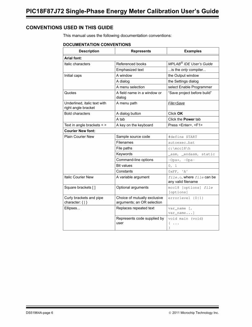
CONVENTIONS USED IN THIS GUIDEThis manual uses the following documentation conventions:
DOCUMENTATION CONVENTIONSDescription Represents Examples
Arial font:Italic characters Referenced books MPLAB® IDE User’s Guide
Emphasized text ...is the only compiler...Initial caps A window the Output window
A dialog the Settings dialogA menu selection select Enable Programmer
Quotes A field name in a window or dialog
“Save project before build”
Underlined, italic text with right angle bracket
A menu path File>Save
Bold characters A dialog button Click OKA tab Click the Power tab
Text in angle brackets < > A key on the keyboard Press <Enter>, <F1>Courier New font:Plain Courier New Sample source code #define START
Filenames autoexec.bat
File paths c:\mcc18\h
Keywords _asm, _endasm, static
Command-line options -Opa+, -Opa-
Bit values 0, 1
Constants 0xFF, ‘A’
Italic Courier New A variable argument file.o, where file can be any valid filename
Square brackets [ ] Optional arguments mcc18 [options] file [options]
Curly brackets and pipe character: { | }
Choice of mutually exclusive arguments; an OR selection
errorlevel {0|1}
Ellipses... Replaces repeated text var_name [, var_name...]
Represents code supplied by user
void main (void){ ...}
DS51964A-page 6 © 2011 Microchip Technology Inc.

Preface
RECOMMENDED READINGThis user’s guide describes how to use the Microchip Single-Phase Energy MeterCalibration Tool. Other useful documents are listed below. The following Microchipdocuments are available and recommended as supplemental reference resources:User’s Guide – “PIC18F87J72 Energy Meter Reference Design”(DS51931A)This user’s guide contains the details of energy meters internal registers and hardware design descriptions.PIC18F87J72 Family Data Sheet – “80-Pin, High-Performance Microcontrollerswith Dual Channel AFE, LCD Driver and nanoWatt Technology” (DS39979)This data sheet provides detailed information regarding the PIC18F87J72 device.AN994 – “IEC61036 Meter Design using the MCP3905A/06A Energy MeteringDevices” (DS00994)This application note describes the design decisions related to the meter design usingthe MCP390X devices and IEC compliance. These are directly related to thePIC18F87J72 and other PIC® based energy meter designs.
THE MICROCHIP WEB SITEMicrochip provides online support via our web site at www.microchip.com. This website is used as a means to make files and information easily available to customers.Accessible by using your favorite Internet browser, the web site contains the followinginformation:• Product Support – Data sheets and errata, application notes and sample
programs, design resources, user’s guides and hardware support documents,latest software releases and archived software
• General Technical Support – Frequently Asked Questions (FAQs), technicalsupport requests, online discussion groups, and the Microchip consultant programmember listing
• Application and Market Support – Specific information on Microchip’s latestsolutions for targeted vertical markets and hardware solutions, includingready-to-use application libraries to support the latest hardware
• Business of Microchip – Product selector and ordering guides, latest Microchippress releases, listing of seminars and events, listings of Microchip sales offices,and distributors and factory representatives
CUSTOMER SUPPORTUsers of Microchip products can receive assistance through several channels:• Distributor or Representative• Local Sales Office• Field Application Engineer (FAE)• Technical SupportCustomers should contact their distributor, representative or field application engineer(FAE) for support. Local sales offices are also available to help customers. A listing ofsales offices and locations is included in the back of this document.Technical support is available through the web site at: http://support.microchip.com
© 2011 Microchip Technology Inc. DS51964A-page 7
PIC18F87J72 Single-Phase Energy Meter Calibration User’s Guide
DOCUMENT REVISION HISTORY
Revision A (June 2011)Initial Release of this Document.
DS51964A-page 8 © 2011 Microchip Technology Inc.
PIC18F87J72 SINGLE-PHASEENERGY METER CALIBRATION
USER’S GUIDE
Chapter 1. Product Overview
1.1 INTRODUCTIONEnergy meters are part of electricity distribution networks, which measure electricityconsumption. Usage of the energy meter in the electricity distribution network requiresthe energy meters to be adaptable to various configurations. This depends on the partof the distribution network and the type of end consumer for which the energy metersare installed. These configurations include a wide range of voltage and current, acrosswhich the meter should be functional, as per the specifications. The aboverequirements demand the metering engine to be adaptable, so that the transducersconverting the input signal are selectable, depending on the specification, while stillrecording the actual values of the input line signal. The meter design is comprised of many components, which may vary in theircharacteristics due to the various factors across the meter design. The components that form part of the circuitry include:• Current Transformer (CT) or Shunt used as a current transducer• Resistive voltage divider as voltage transducer• Resistors • Capacitors• InductorsThese variations in characteristics have an impact on measured signals, which mayresult in offset addition, amplitude alteration and change in signal phase. Considering all the above factors, the standard value calibration needs to be carriedout to achieve meter output. Calibration is the process where the line parameters areset to known values and the various signal conditioning parameters such as gain, offsetcompensation, and phase compensation factors are calculated.The calibration process should be comprehensive. The process should aid meterdesign by selecting the various transducers, and should be fast enough to reduce theproduction line assembly time. The calibration should be accountable for thespecifications like accuracy, class, and various parameters that need to be measuredby the meter. The above requirements necessitate that the calibration process shouldbe:• Fast to aid production line calibration• Achieve required meter specifications in one iteration• Give information about the value of transducers required for a particular specifica-
tion of the meter, aiding meter design• Modular such that only required meter output parameter can be calibrated to
desired level of accuracyDifferent types of calibrations, considering all the above factors, are described in thefollowing chapters.
© 2011 Microchip Technology Inc. DS51964A-page 9

PIC18F87J72 Single-Phase Energy Meter Calibration User’s Guide
NOTES:
DS51964A-page 10 © 2011 Microchip Technology Inc.

PIC18F87J72 SINGLE-PHASEENERGY METER CALIBRATION
USER’S GUIDE
Chapter 2. Meter Calibration
2.1 INTRODUCTIONThis chapter describes the method to calculate calibration parameters. It includesvarious types of calibration suitable for different stages of meter design.
2.2 TYPES OF CALIBRATIONBased on the type of meter accuracy class, and the stages of meter development, thedifferent types of calibration options provided are: • Closed Loop Calibration• Multipoint Calibration• Single Point CalibrationDuring the calibration process, the following register values are computed:• Gain registers
- GAIN_V_RMS- GAIN_I_RMS- GAIN_POWER_ACT- GAIN_POWER_REACT- GAIN_NUMR_ENERGY_ACT- GAIN_DENR_ENERGY_ACT- GAIN_NUMR_ENERGY_REACT- GAIN_DENR_ENERGY_REACT
• Offset registers- OFFSET_I_RMS- OFFSET_V_RMS- OFFSET_POWER_ACT- OFFSET_POWER_REACT
• Phase compensation register- PHASE_COMPENSATION
• Creep threshold for No Load condition- CREEP_THRSHOLD_MINUTE- CREEP_THRSHOLD_SECOND
The calibration flow charts, procedures and equation presented in this section are all automated using Microchip’s “Single Phase Energy Meter Calibration Software”, downloadable from the Energy Meter product page. The calibration software features multiple tabs, offering three different calibration processes.
Note: For descriptions on these registers, refer to User’s Guide – “PIC18F87J72 Energy Meter Reference Design”(DS51931)
© 2011 Microchip Technology Inc. DS51964A-page 11

PIC18F87J72 Single-Phase Energy Meter Calibration User’s Guide
2.2.1 Calibration RequirementsThe calibration requirements for the Closed Loop, Multipoint and Single PointCalibration process are:• Requirement for Closed Loop CalibrationClosed loop calibration requires a reference meter. The reference meter is an accuratemeasurement source capable of measuring the line parameters and the output of themeter under calibration simultaneously, and gives the percentage difference.Calibration using a reference meter is common practice in the industry, which isadopted in the Closed Loop Calibration. To measure the output of the meter undercalibration, the calibration pulse rate (CF pulse) is used, which is proportional to theenergy accumulated by the meter. The rate of CF pulse of the meter and the referencemeter are compared to calculate this percentage error (Error %). This Error % is usedas feedback to calibrate the meter. The Closed Loop Calibration method reads themeter output as an average value over a period. Therefore, even if the line input is notfrom a highly accurate input source, it will not be a limitation during the closed loopcalibration.• Requirement for Multipoint and Single Point CalibrationThe accurate source that feeds the line parameters precisely is used in the multipointand single point calibration. In this calibration process, the parameter under calibrationis measured over a definite period, under the condition that the input is precisely set toa known value without any fluctuations. Based on this, various calibration registervalues are computed theoretically. As the calibration does not involve any feedback,the source feeding the line parameters must be highly accurate to achieve the desiredaccuracy class.
2.3 CLOSED LOOP CALIBRATIONThe Closed Loop Calibration process involves taking feedback from the meter outputand comparing it with the reference meter for the given parameter values. Error % inthe meter output with respect to the standard reference meter is calculated, and theregister values are adjusted until the desired level of accuracy is achieved. Closed Loop Calibration includes two configurations, offered as a modular process:• Power Calibration• Energy Calibration During these stages, various meter outputs are calibrated, and include:• RMS Voltage• RMS Current• Active Power• Reactive Power• Apparent Power• Active Energy• Reactive EnergyAll the above meter outputs can be calibrated independently, with the fewdependencies based on the accuracy class of the meter under calibration. The method of calibrating these separate signal flows can be combined into fivedifferent stages in the power calibration tab, and three different stages in the energycalibration tab. These stages consist of supplying specific voltage and current atspecific phase angles to the meter and input the Error % in energy registered in thereference meter.
DS51964A-page 12 © 2011 Microchip Technology Inc.

Meter Calibration
Depending on the accuracy and the meter type, all calibration stages are not requiredto calibrate a meter completely. In some cases, only a few calibration stages arerequired. The software allows individual stages to be carried out independently, duringthe calibration flow.
2.3.1 Generic Flow chart for closed Loop calibrationFigure 2-1 represents the generic calibration process followed for:• RMS Voltage• RMS Current• Active Power• Reactive Power
FIGURE 2-1: Generic Flow Chart for Closed Loop Calibration.
Start
Is Calibrate Button Pressed
Read Meter Output Line Parameter
Is Error within Specification or 5 times Iterations
Completed?
Calculate Gain using Formula (in Gain Compensation)
Write New Gain to Meter
Wait for New Gain to take Effect
NO
YES
NO
YES
Compute Error Percentage with respect to Input Line Parameter
Stop
Input to meterEnter Line Parameter Value
© 2011 Microchip Technology Inc. DS51964A-page 13
PIC18F87J72 Single-Phase Energy Meter Calibration User’s Guide
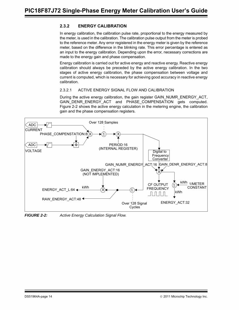
2.3.2 ENERGY CALIBRATIONIn energy calibration, the calibration pulse rate, proportional to the energy measured bythe meter, is used in the calibration. The calibration pulse output from the meter is probedto the reference meter. Any error registered in the energy meter is given by the referencemeter, based on the difference in the blinking rate. This error percentage is entered asan input to the energy calibration. Depending upon the error, necessary corrections aremade to the energy gain and phase compensation.Energy calibration is carried out for active energy and reactive energy. Reactive energycalibration should always be preceded by the active energy calibration. In the twostages of active energy calibration, the phase compensation between voltage andcurrent is computed, which is necessary for achieving good accuracy in reactive energycalibration.
2.3.2.1 ACTIVE ENERGY SIGNAL FLOW AND CALIBRATION
During the active energy calibration, the gain register GAIN_NUMR_ENERGY_ACT,GAIN_DENR_ENERGY_ACT and PHASE_COMPENSATION gets computed.Figure 2-2 shows the active energy calculation in the metering engine, the calibrationgain and the phase compensation registers.
FIGURE 2-2: Active Energy Calculation Signal Flow.
X Σ
Φ
PHASE_COMPENSTATION:8
ADC
ADC
CURRENT
VOLTAGE Digital toFrequencyConverter
GAIN_NUMR_ENERGY_ACT:16 GAIN_DENR_ENERGY_ACT:8
CF OUTPUTFREQUENCYkWh
X
GAIN_ENERGY_ACT:16
ENERGY_ACT_L:64
RAW_ENERGY_ACT:48ENERGY_ACT:32
X
PERIOD:16
Σ
Over 128 Signal
Σ 1/METER
(INTERNAL REGISTER)
Cycles
CONSTANT
Over 128 Samples
kWh
(NOT IMPLEMENTED)
kWh
X
DS51964A-page 14 © 2011 Microchip Technology Inc.

Meter Calibration
2.3.2.2 ACTIVE ENERGY GAIN COMPUTATION
Active energy gain is computed as the percentage ratio of the error recorded againstthe previous gain. The Error % is the difference between the input line active energyand the meter output as recorded by the reference meter. Active energy gain is com-puted using Equation 2-1.
EQUATION 2-1: ACTIVE ENERGY GAIN COMPUTATION
2.3.2.3 PHASE COMPENSATION
Due to reactive components in the signal flow path, the voltage and current may not bein phase at PF = 1.0. Therefore, the voltage and current samples measured will havea small phase offset, that may affect the energy accuracy. To rectify the offset, phasecompensation is introduced, which shifts the voltage/current samples by correspondingangle through an interpolation method.
2.3.2.3.1 Phase Compensation CalculationEquations 2-2 to 2-6 shows the calculation of different stages of phase compensation.
EQUATION 2-2: ENERGY WITH PHASE ERROR AT PF = 1.0
EQUATION 2-3: ENERGY WITH PHASE ERROR AT PF = 0.5 LAG
Then,
GAIN_NUMR_ENERGY_ACT (New Value) = GAIN (New Value) / 2
GAIN_DENR_ENERGY_ACT(New Value) = GAIN_DENR_ENERGY_ACT(Old Value) + 1
else,
GAIN_NUMR_ENERGY_ACT (New Value = GAIN (New Value)
GAIN_DENR_ENERGY_ACT (New Value) = GAIN_DENR_ENERGY_ACT (Old Value) )
GAIN NewValue( )
GAIN OldValue( )Error%
100------------------⎝ ⎠⎛ ⎞ 1+
--------------------------------------------=
If GAIN > 65535
Energy at PF = 1.0 ( Φ= 0o):
EUPF = VRMS x IRMS x Cos( Φ+ β) x Period = VRMS x IRMS x Cos( β) x Period
Where:
Φ = Input Phase between V and I β = Phase deviation between V and I, β Є [-90°, +90°]
Energy at PF = 0.5 lag ( Φ= 60o):
EPF0.5_error = VRMS x IRMS x Cos( Φ + β) x Period
= VRMS x IRMS x Cos( 60 + β) x Period
Where:
Φ = Input Phase between V and I β = Phase deviation between V and I, β Є [-90°, +90°]
© 2011 Microchip Technology Inc. DS51964A-page 15

PIC18F87J72 Single-Phase Energy Meter Calibration User’s Guide
EQUATION 2-4: ENERGY WITHOUT PHASE ERROR AT PF = 0.5 LAG
EQUATION 2-5: PHASE COMPENSATION ANGLE CALCULATION
EQUATION 2-6: PHASE COMPENSATION FACTOR CALCULATION
2.3.2.3.2 Phase Compensation between Voltage and CurrentTo determine the state of the signal between the two successive samples, use theinterpolation method. If x(Θ-N) and x(Θ) are known, where, “Θ” is the phase of signal that can vary between0o to 360o and “N” is the angle between two successive samples = (360 * frequency ofsignal/sampling rate), then it is possible to determine the state of the signal at any inter-val between ‘Θ-N’ and ‘Θ’ with an assumption that signal varies linearly in theintermediate region as shown in Equation 2-7. To apply this method to a line signal, the sampling rate has to be selected such that theinterval between successive samples is small. This ensures that the above statedassumption holds true.
Note 1: The Sign convention of Phase Compensation angle is:• Positive, if the current leads voltage• Negative, if the current lags voltage
Actual Energy at PF = 0.5 lag ( Φ = 60o ):
EPF0.5 = VRMS x IRMS x Cos( ø ) x Period
= VRMS x IRMS x Cos( 60 ) x Period
Where:
Φ = Input Phase between V and I
Error = (EPF0.5 - EPF0.5_error ) * 100 / EPF0.5
Error/100 = 1 – (EPF0.5_error / EPF0.5)
Substituting equations and simplify:
Error/100 = 1 – (Cos(60 + β) / Cos(60))
= 1 – (Cos(60 + β) / 0.5)
Cos(60 + β) = 0.5 x (1 + Error/100) = n
β = [COS-1 (n) – 60] in degree is the phase compensation angle
PHASE_COMPENSATION = β x 128 / Angle between samples
= β x 128 / 5.529o
Angle between samples = 360o / Samples per sine cycle
= 360o / 65.1
= 5.529o
Samples per sine cycle = Sampling rate/Frequency of Signal
= 3906 / 60Hz
= 65.1 samples per cycle
Magnitude of Phase compensation factor:
PHASE_COMPENSATION (magnitude) = |PHASE_COMPENSATION |
= PHASE_COMPENSATION x 2
DS51964A-page 16 © 2011 Microchip Technology Inc.

Meter Calibration
EQUATION 2-7: CALCULATIONS WITH THE INTERPOLATION METHOD
Equation 2-7 implements the linear interpolation on the previous sample of voltage forthe phase compensation. The present or the previous sample of current is considered,depending on the voltage lag or lead condition respectively, as explained in Case1 andCase 2, thus accounting to compensate phase by a maximum angle of ±N/2.Case 1: Current Leads Voltage by Angle βPhase correction factor “PHASE_COMPENSATION” is calculated for the correctionangle ‘β’ as explained in Equation 2-5 and Equation 2-6. In this case ‘β’ is positive, there-fore “PHASE_COMPENSATION” value will be positive as explained in Note 1.As the current leads the voltage during phase compensation, the voltage sample needsto be given a lead by an angle ‘β’. From the interpolation method, it is possible to deter-mine X(Θ + β) from X(Θ) and X(Θ - N) and achieve a lead. The lead can only be appliedto the previous sample, but not to the present sample.Therefore, keeping the above argument in consideration to compensate the currentlead:• Phase compensation is carried out on the voltage sample, introducing a lead by
using the present and the previous sample of voltage. This phase lead is appliedto the previous sample of voltage.
• As the phase lead is applied to the previous sample of voltage, the correspondingprevious sample of current is considered. This compensation brings voltage andcurrent in synchronization.
Case 2: Current Lags Voltage by Angle βThe phase correction factor “PHASE_COMPENSATION”, is calculated for thecorrection angle ‘β’ as explained in Equation 2-5 and Equation 2-6. In this case, ‘β’ isnegative, therefore the “PHASE_COMPENSATION” value will be negative asexplained in Note 1.As the current lags voltage during phase compensation, the voltage sample needs tobe given a lead by angle ‘N-β’. From the interpolation method, it is possible to deter-mine X[Θ + N - β] from X(Θ) and X(Θ-N) as Θ-N ≤ Θ+ N-β ≤ Θ and achieve a lead. Thelead can only be applied to the previous sample, but not to the present sample.Therefore, keeping the above argument in consideration in order to compensate thecurrent lag:• Phase compensation is carried out on the voltage sample, introducing a lead by
using the present and the previous sample of voltage. This phase lead is applied tothe previous sample of voltage.
• As the phase lead is applied to the previous sample of voltage, the present sample ofcurrent is considered. This compensation brings voltage and current insynchronization.
Consider, X(Θ) and X(Θ - N) as known samples
X[Θ + β] = X[Θ] + (X[Θ] - X[Θ - N] ) * PHASE_COMPENSATION (magnitude)/256
Where:
Θ - N ≤ Θ + β ≤ ΘΘ = Varies between 0 and 360°N = Angle between successive samples = (360 * frequency of signal / sampling rate)
PHASE_COMPENSATION value is derived from Equations 2-2 to 2-6.
© 2011 Microchip Technology Inc. DS51964A-page 17

PIC18F87J72 Single-Phase Energy Meter Calibration User’s Guide
2.3.2.4 ACTIVE ENERGY CALIBRATION PROCEDURE
The active energy calibration (kWh) consists of two stages:STAGE 1During Stage 1, the active energy gain compensation gets computed at PF = 1.0 lag.Depending on the type, value of voltage and current transducers, the value of gaincompensation varies to measure the standard value of energy.1. At PF = 1.0, the active energy calibration pulse output is probed. The Error % is
entered into the Stage 1 calibration software, as shown in Figure 2-3. 2. Click Calibrate to proceed with the calibration. During this stage, the gain of the
active energy will be calibrated.3. After completion of the process, the active energy pulse output is probed and the
Error % is recorded. If the meter output is within the specification, the activeenergy calibration Stage 1 can be stopped.
FIGURE 2-3: Active Energy Calibration Stage 1.
DS51964A-page 18 © 2011 Microchip Technology Inc.

Meter Calibration
STAGE 2During this stage, phase compensation will be computed at PF = 0.5 lag. Due to vari-ous components in the board design, there may be a phase delay between the voltageand the current.1. To compensate for the phase delay, the meter line inputs are set at PF = 0.5 lag
and the active energy calibration pulse output is probed.2. The Error % registered in the reference meter is entered as an input to Stage 2
calibration. Click Calibrate to initiate the phase compensation calibration asshown in Figure 2-4.
3. After completion of the process, the meter active energy pulse output is probedand the Error % is recorded. To confirm accurate phase compensation, the activeenergy at various PF can be checked, during which the accuracy must be withinthe specification. If the meter output is within the specification, active energycalibration Stage 2 can be stopped.
FIGURE 2-4: Active Energy Calibration Stage 2.
© 2011 Microchip Technology Inc. DS51964A-page 19

PIC18F87J72 Single-Phase Energy Meter Calibration User’s Guide
2.3.3 Reactive Energy Signal Flow and CalibrationDuring reactive energy calibration, the gain register GAIN_NUMR_ENERGY_REACT, GAIN_DENR_ENERGY_REACT gets computed. Figure 2-5 shows the reactive energy calculation in the metering engine and the calibration gain register.
FIGURE 2-5: Reactive Energy Calculation Signal Flow.
2.3.3.1 REACTIVE ENERGY GAIN COMPUTATION
Reactive energy gain is computed as a percentage ratio of the error recorded against the previous gain. The Error % is the difference between the input line reactive energy and the meter output, as recorded by the reference meter. Reactive energy gain is computed using Equation 2-8.
EQUATION 2-8: REACTIVE ENERGY GAIN COMPUTATION
X Σ
Φ
PHASE_COMPENSTATION:8
ADC
ADC
CURRENT
VOLTAGE Digital toFrequencyConverter
/
GAIN_NUMR_ENERGY_REACT:16 GAIN_DENR_ENERGY_REACT:8
CF OUTPUTFREQUENCYkVARh
X
GAIN_ENERGY_REACT:16
ENERGY_REACT_L:64
RAW_ENERGY_REACT:48ENERGY_REACT:32
X
PERIOD:16
Σ
Over 128 Signal
Σ 1/METER
(INTERNAL REGISTER)
Cycles
CONSTANT
Over 128 Samples
kVARh
(NOT IMPLEMENTED)
+
90° PHASE SHIFTER
Note 1: 90° PHASE SHIFTER is implemented as a low-pass filter in cutoff band and a phase compensator.2: α is a phase compensator to compensate small angles to get exact 90° phase shift in conjunction with the
low- pass filter.
kVARh
α(2)
(1)
If GAIN > 65535
Then,
GAIN_NUMR_ENERGY_REACT (New Value) = GAIN (New Value) / 2
GAIN_DENR_ENERGY_REACT(New Value) = GAIN_DENR_ENERGY_REACT(Old Value) + 1
else,
GAIN_NUMR_ENERGY_REACT (New Value = GAIN (New Value)
GAIN_DENR_ENERGY_REACT (New Value) = GAIN_DENR_ENERGY_REACT (Old Value) )
GAIN NewValue( )
GAIN OldValue( )Error%
100------------------⎝ ⎠⎛ ⎞ 1+
--------------------------------------------=
DS51964A-page 20 © 2011 Microchip Technology Inc.

Meter Calibration
2.3.3.2 REACTIVE ENERGY CALIBRATION PROCEDURE
In reactive energy calibration stage, the reactive energy calibration pulse output isprobed and the percentage error (Error %) is entered as an input to the calibrationsoftware as shown in Figure 2-6. To calibrate the reactive energy, the phasecompensation should be calibrated, which otherwise may be erroneous. The reactiveenergy calibration is similar to Stage 1 of active energy calibration, during which thegain of the reactive energy is calibrated.1. At PF = 0.5 lag, the reactive energy calibration pulse output is probed and the
percentage error (Error %) is entered as an input to the calibration software. 2. Click Calibrate to proceed with calibration. During this stage, the gain of the
reactive energy is calibrated.3. After the completion of the process, the meter reactive energy pulse output is
probed and the error percentage is recorded, in comparison with the referencemeter output. If the meter output is within the specification, the reactive energycalibration can be stopped.
FIGURE 2-6: Reactive Energy Calibration.
© 2011 Microchip Technology Inc. DS51964A-page 21

PIC18F87J72 Single-Phase Energy Meter Calibration User’s Guide
2.3.4 Power CalibrationIn Power Calibration, the line parameter measured by the reference meter, is enteredas an input to the calibration software. The difference between the output of the meterunder the calibration, and the reference meter is computed. The Error % is used asfeedback to adjust the calibration parameters accordingly. In power calibration configuration, Active power, Reactive Power, RMS Voltage andRMS Current get calibrated.
2.3.4.1 VOLTAGE SIGNAL FLOW AND CALIBRATION
During voltage calibration, the gain register GAIN_V_RMS gets computed. Figure 2-7shows the voltage calculation in the metering engine and the calibration gain register.
FIGURE 2-7: RMS Voltage Calculation Signal Flow.
2.3.4.1.1 Voltage Gain ComputationVoltage gain is computed as a percentage ratio of the error, recorded against theprevious gain. The Error % is the difference between the input line voltage and themeter output.
EQUATION 2-9: VOLTAGE GAIN COMPUTATION
2.3.4.1.2 Voltage Calibration ProcedureTo calibrate the RMS voltage output of the meter, follow this procedure:1. Enter the input line voltage value in “Calibration Voltage (V)” and click Calibrate
to initiate the calibration, as shown in Figure 2-8.2. After completion of the process, the meter output voltage will be displayed along
with the Error % in comparison with the input line voltage.3. If the meter output is within the specification, the voltage calibration can be
stopped.
X2 Σ
OFFSET_V_RMS:16
ADC
VOLTAGE X
GAIN_V_RMS:16
V_RMS:16
RAW_V_RMS:16
Σ
Over 128 SignalCycles
Average
Note: The Error % is used as an input for the calibration software.
GAIN_V_RMS NewValue( )
GAIN_V_RMS OldValue( )Error%
100------------------⎝ ⎠⎛ ⎞ 1+
------------------------------------------------------------------=
DS51964A-page 22 © 2011 Microchip Technology Inc.
Meter Calibration
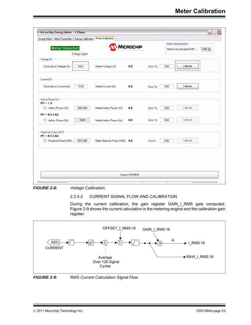
FIGURE 2-8: Voltage Calibration.
2.3.4.2 CURRENT SIGNAL FLOW AND CALIBRATION
During the current calibration, the gain register GAIN_I_RMS gets computed.Figure 2-9 shows the current calculation in the metering engine and the calibration gainregister.
FIGURE 2-9: RMS Current Calculation Signal Flow.
CURRENTX2 Σ
OFFSET_I_RMS:16
ADC XA
GAIN_I_RMS:16
I_RMS:16
RAW_I_RMS:16
Σ
Over 128 SignalCycles
Average
© 2011 Microchip Technology Inc. DS51964A-page 23

PIC18F87J72 Single-Phase Energy Meter Calibration User’s Guide
2.3.4.2.1 Current Gain ComputationCurrent gain is computed as a percentage ratio of the error recorded against theprevious gain. The Error % is the difference between the input line current and themeter output.
EQUATION 2-10: CURRENT GAIN COMPUTATION
2.3.4.2.2 Current Calibration ProcedureTo calibrate the RMS current output of the meter, follow this procedure:1. Enter the input line current value in “Calibration Current (A)” and click Calibrate
to initiate the calibration, as shown in Figure 2-10.2. After completion of the process, the meter output current will be displayed along
with the Error % in comparison with the input line current.3. If the meter output is within the specification, then the current calibration can be
stopped.
FIGURE 2-10: Current Calibration.
GAIN_I_RMS NewValue( )
GAIN_I_RMS OldValue( )Error%
100------------------⎝ ⎠⎛ ⎞ 1+
----------------------------------------------------------------=
DS51964A-page 24 © 2011 Microchip Technology Inc.

Meter Calibration
2.3.4.3 ACTIVE POWER SIGNAL FLOW AND CALIBRATION
During Active Power Calibration, the gain registers GAIN_POWER_ACT andPHASE_COMPENSATION get computed. Figure 2-11 shows the active powercalculation in the metering engine, the calibration gain and the phase compensationregisters.
FIGURE 2-11: Active Power Calculation Signal Flow
2.3.4.3.1 Active Power Gain ComputationActive Power Gain is computed as a percentage ratio of the error recorded against theprevious gain. The Error % is the difference between the input line active power andthe meter output, as shown in Equation 2-11.
EQUATION 2-11: ACTIVE POWER GAIN COMPUTATION
2.3.4.3.2 Active Power Calibration ProcedureThe Active Power (W) calibration in the meter consists of two stages:STAGE 11. During Stage 1 at PF = 1.0 lag, the active power read by the reference meter is
entered as an input, and the active power calibration Stage 1 is selected asshown in Figure 2-12.
2. Click Calibrate to proceed with calibration. During this stage, the gain of theactive power will be calibrated.
3. After the completion of the process, the meter active power output will be dis-played along with the Error %, in comparison with the reference meter output. Ifthe meter output is within the specification, the active power calibration Stage 1can be stopped.
X Σ
OFFSET_POWER_ACT:32Φ
PHASE_COMPENSATION:8
ADC
ADC
CURRENT
VOLTAGE
XkW
GAIN_POWER_ACT:16
POWER_ACT:32
RAW_POWER_ACT:64
Σ Σ
Over 128 Samples
Over 128 SignalCycles
Average
Note: Stage 2 of active power calibration includes the phase compensation factorcalculation. This calibration is also included in the second stage of activeenergy calibration. If the meter configuration includes both active energyand power calibration, then it is suggested to calibrate the phasecompensation factor in the energy calibration stage and skip this stepduring power calibration.
Note: Phase compensation is explained in Stage 2 of Energy Calibration(Equations 2-2 to 2-6).
GAIN_POWER_ACT NewValue( )
GAIN_POWER_ACT OldValue( )Error%
100------------------⎝ ⎠⎛ ⎞ 1+
----------------------------------------------------------------------------------=
© 2011 Microchip Technology Inc. DS51964A-page 25

PIC18F87J72 Single-Phase Energy Meter Calibration User’s Guide
FIGURE 2-12: Active Power Phase 1 Calibration.
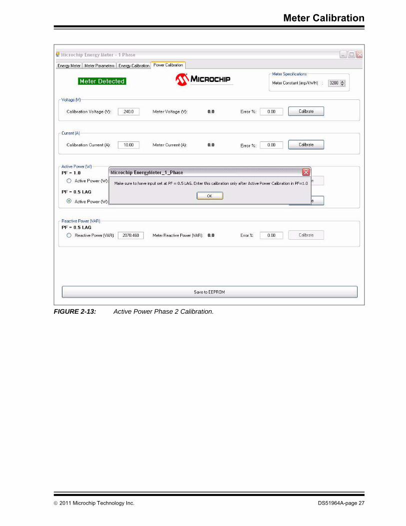
STAGE 2During this stage, phase compensation will be computed at PF = 0.5 lag.1. During Stage 2, meter line inputs are set at PF = 0.5 lag, with the active power
being exactly half of PF = 1.0.2. The phase compensation calibration is initiated by selecting Stage 2 of the active
power calibration, as shown in Figure 2-13. 3. Click Calibrate to proceed with the calibration.4. After the completion of this process, the meter active power output will be
displayed along with the Error %, in comparison with that of the reference meteroutput. After the calibration, the meter output should be exactly half of the activepower value that was calibrated at the Stage 1. If the meter output is within thespecification, active power calibration Stage 2 can be stopped.
DS51964A-page 26 © 2011 Microchip Technology Inc.
Meter Calibration
FIGURE 2-13: Active Power Phase 2 Calibration.
© 2011 Microchip Technology Inc. DS51964A-page 27
PIC18F87J72 Single-Phase Energy Meter Calibration User’s Guide
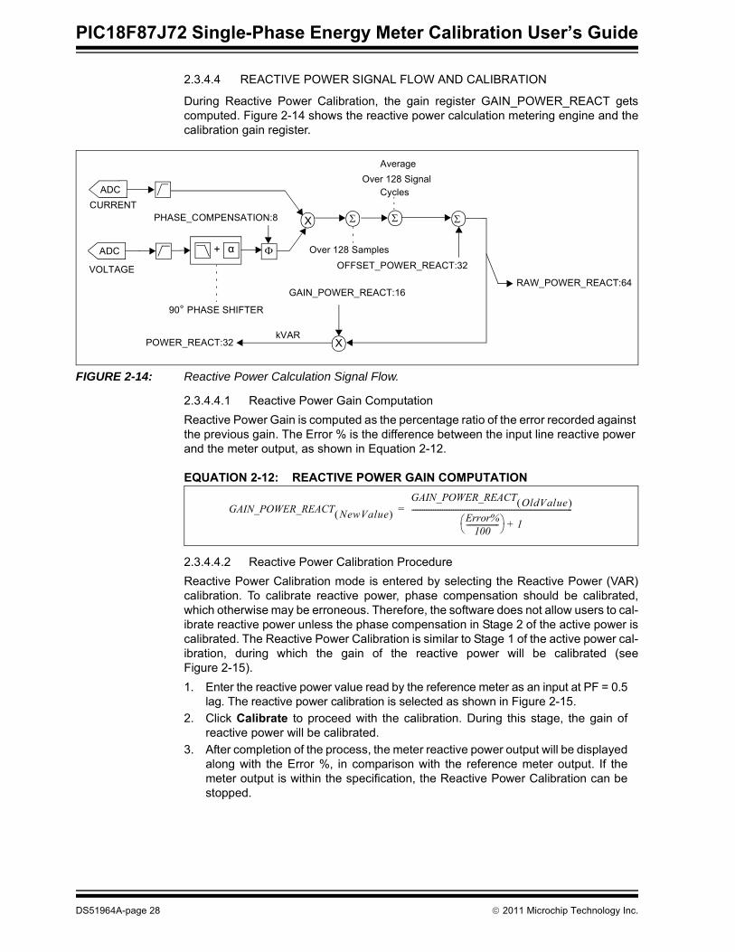
2.3.4.4 REACTIVE POWER SIGNAL FLOW AND CALIBRATION
During Reactive Power Calibration, the gain register GAIN_POWER_REACT getscomputed. Figure 2-14 shows the reactive power calculation metering engine and thecalibration gain register.
FIGURE 2-14: Reactive Power Calculation Signal Flow.
2.3.4.4.1 Reactive Power Gain ComputationReactive Power Gain is computed as the percentage ratio of the error recorded against the previous gain. The Error % is the difference between the input line reactive power and the meter output, as shown in Equation 2-12.
EQUATION 2-12: REACTIVE POWER GAIN COMPUTATION
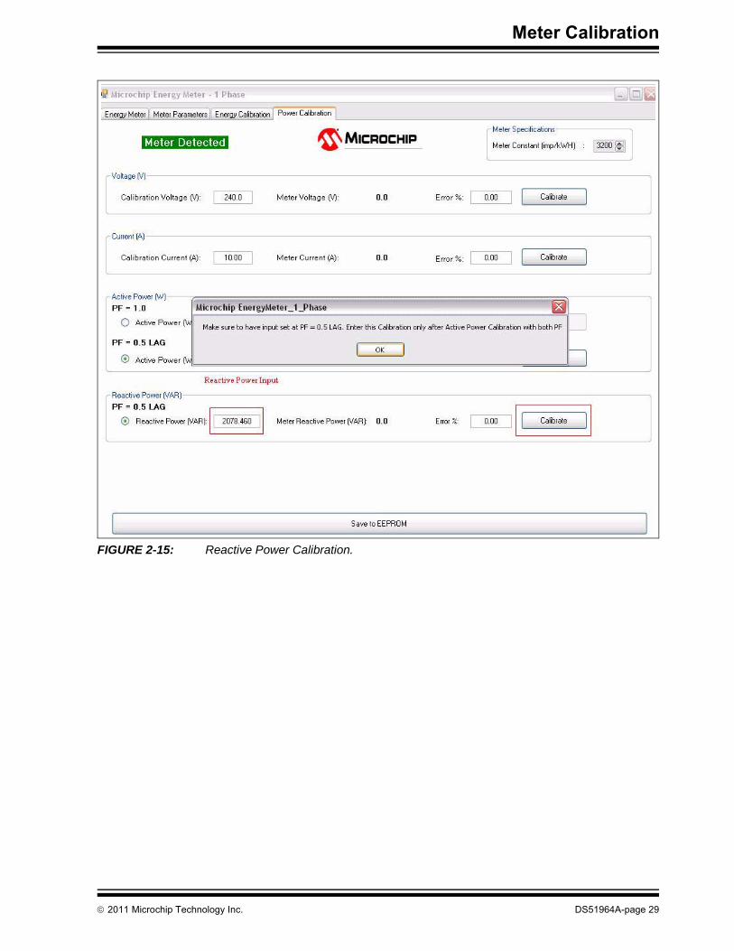
2.3.4.4.2 Reactive Power Calibration ProcedureReactive Power Calibration mode is entered by selecting the Reactive Power (VAR)calibration. To calibrate reactive power, phase compensation should be calibrated,which otherwise may be erroneous. Therefore, the software does not allow users to cal-ibrate reactive power unless the phase compensation in Stage 2 of the active power iscalibrated. The Reactive Power Calibration is similar to Stage 1 of the active power cal-ibration, during which the gain of the reactive power will be calibrated (seeFigure 2-15).1. Enter the reactive power value read by the reference meter as an input at PF = 0.5
lag. The reactive power calibration is selected as shown in Figure 2-15.2. Click Calibrate to proceed with the calibration. During this stage, the gain of
reactive power will be calibrated.3. After completion of the process, the meter reactive power output will be displayed
along with the Error %, in comparison with the reference meter output. If themeter output is within the specification, the Reactive Power Calibration can bestopped.
X Σ
OFFSET_POWER_REACT:32Φ
PHASE_COMPENSATION:8
ADC
ADC
CURRENT
VOLTAGE
XkVAR
GAIN_POWER_REACT:16
POWER_REACT:32
RAW_POWER_REACT:64
Σ Σ
Over 128 Samples
Over 128 SignalCycles
α+
Average
90° PHASE SHIFTER
GAIN_POWER_REACT NewValue( )
GAIN_POWER_REACT OldValue( )Error%
100------------------⎝ ⎠⎛ ⎞ 1+
-----------------------------------------------------------------------------------------=
DS51964A-page 28 © 2011 Microchip Technology Inc.
Meter Calibration
FIGURE 2-15: Reactive Power Calibration.
© 2011 Microchip Technology Inc. DS51964A-page 29

PIC18F87J72 Single-Phase Energy Meter Calibration User’s Guide
2.4 MULTIPOINT CALIBRATIONMultipoint Calibration calculates the gain and offset theoretically, based on the inputline parameters. The line parameters are set to defined values, which are entered asan input to the calibration software. This calibration is suitable for the development pro-cess, to get an insight on gain and offset to the gain and offset calculations for signalconditioning.
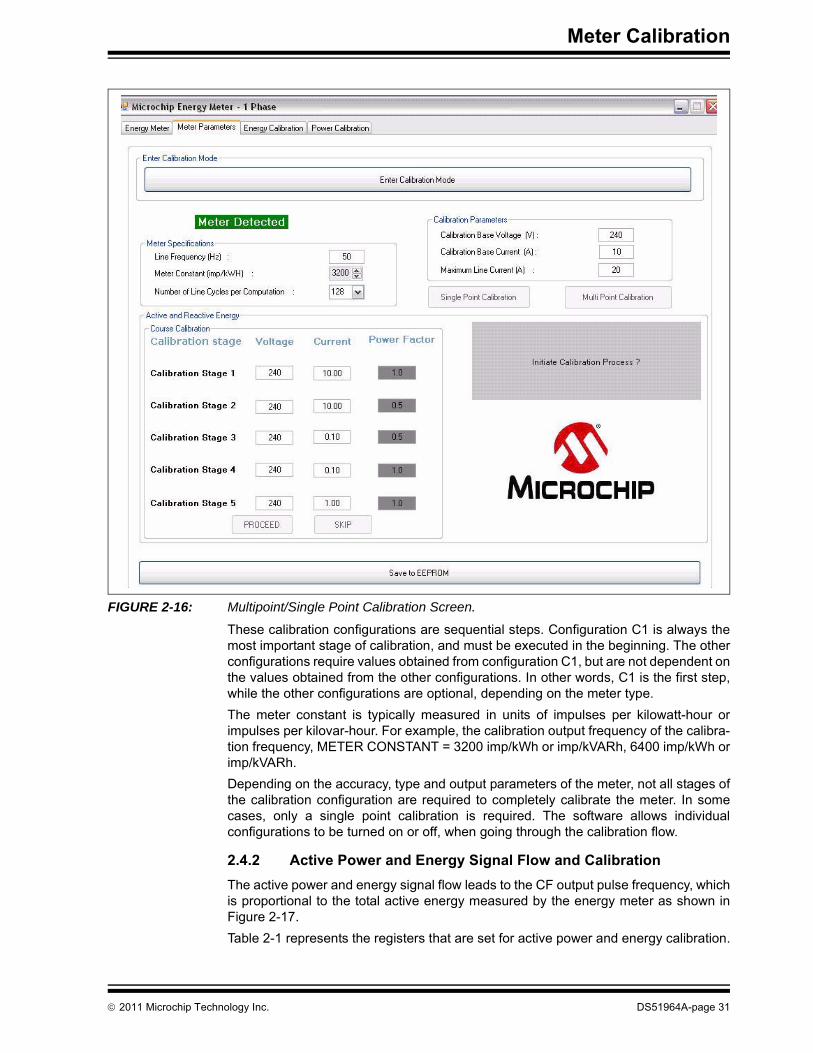
2.4.1 IB, VB, Meter Constant and Calibration ConfigurationsThe calibration of the single phase energy meter involves up to five differentconfigurations, as shown in Figure 2-16.
EXAMPLE 2-1:
1. Calibration Stage C1: Active Power, Energy and RMS Voltage Gain Calibration, Gain – Basic voltage VB and basic current IB at a power factor of 1. For example, 220V and 5A.
2. Calibration Stage C2: Phase Compensation, Reactive Power and Energy GainCalibration – Basic 220V and 5A voltage VB and basic current IB at a power factorof 0.5 lag.
3. Calibration Stage C3: Reactive Power Offset – Base voltage VB and 1/100 of base current IB at PF = 0.5 lag at 220V and 50 mA.
4. Calibration Stage C4: Active Power Offset – Basic voltage VB and 1/100 of IB at a power factor of 1. For example, 220V and 50 mA.
5. Calibration Stage C5: Current Gain and Offset Calibration – Mid-range – Basic voltage VB and 1/10 of IB at a power factor of 1. For example, 220V and 500 mA.
Meter design with base operational condition is 5(10)A, IB = 5, IMAX = 10A.
DS51964A-page 30 © 2011 Microchip Technology Inc.
Meter Calibration
FIGURE 2-16: Multipoint/Single Point Calibration Screen.
These calibration configurations are sequential steps. Configuration C1 is always themost important stage of calibration, and must be executed in the beginning. The otherconfigurations require values obtained from configuration C1, but are not dependent onthe values obtained from the other configurations. In other words, C1 is the first step,while the other configurations are optional, depending on the meter type.The meter constant is typically measured in units of impulses per kilowatt-hour orimpulses per kilovar-hour. For example, the calibration output frequency of the calibra-tion frequency, METER CONSTANT = 3200 imp/kWh or imp/kVARh, 6400 imp/kWh orimp/kVARh.Depending on the accuracy, type and output parameters of the meter, not all stages ofthe calibration configuration are required to completely calibrate the meter. In somecases, only a single point calibration is required. The software allows individualconfigurations to be turned on or off, when going through the calibration flow.
2.4.2 Active Power and Energy Signal Flow and CalibrationThe active power and energy signal flow leads to the CF output pulse frequency, whichis proportional to the total active energy measured by the energy meter as shown inFigure 2-17. Table 2-1 represents the registers that are set for active power and energy calibration.
© 2011 Microchip Technology Inc. DS51964A-page 31

PIC18F87J72 Single-Phase Energy Meter Calibration User’s Guide
TABLE 2-1: CALIBRATION REGISTERS GENERATED THROUGH THIS ROUTINE
FIGURE 2-17: Active Power and Energy Signal Path Showing Output and Calibration Registers.
Register Name Equations Configurations Required
GAIN_DENR_ENERGY_ACT Section 2.4.4.1 “Equations for Configuration C1 Calibration – Active Energy and Active
Power”
C1 ONLY
GAIN_NUMR_ENERGY_ACT Section 2.4.4.1 “Equations for Configuration C1 Calibration – Active Energy and Active
Power”
C1 ONLY
PHASE_COMPENSATION Section 2.4.7.1 “Equations for Configuration C2 Calibration – Phase Delay”
C1, C2
OFFSET_POWER_ACT Section 2.4.9.1 “Equations for Configuration C4 Calibration – Active Power Offset”
C1, C4
GAIN_POWER_ACT Section 2.4.4.1 “Equations for Configuration C1 Calibration – Active Energy and Active
Power”
C1 ONLY
GAIN_ENERGY_ACT Not Implemented Not Implemented
X Σ
OFFSET_POWER_ACT:32Φ
PHASE_COMPENSTAION:8
ADC
ADC
CURRENT
VOLTAGE
XkW
kWhX
GAIN_POWER_ACT:16
GAIN_ENERGY_ACT:16 (NOT IMPLEMENTED)
ENERGY_ACT_L:32
POWER_ACT:32
RAW_ENERGY_ACT:64
RAW_POWER_ACT:48
X
PERIOD:16 (INTERNAL REGISTER)
Digital toFrequencyConverter
/
GAIN_NUMR_ENERGY_ACT:16 GAIN_DENR_ENERGY_ACT:8
CF OUTPUTFREQUENCY
ENERGY_ACT:32
Σ 1/METER CONSTANT
kWh
kWh
DS51964A-page 32 © 2011 Microchip Technology Inc.

Meter Calibration
2.4.3 RMS Current, RMS Voltage, Signal Flow and CalibrationThe RMS current and voltage outputs require a two-point calibration at configurationsC1 and C5. The automated software performs these calibrations, suggested on thecalibration values entered in the text boxes, as shown in Figure 2-16.Table 2-2 and Figure 2-18 represent the registers that are set for RMS current and voltage calibration.
TABLE 2-2: RMS CURRENT, RMS VOLTAGE, CALIBRATION REGISTERS
FIGURE 2-18: RMS Current and Voltage Flow.
Register Equation Configurations Required
OFFSET_V_RMS Section 2.4.10.1 “Equations for Configuration C5 Calibration – RMS Voltage and Current”
C1, C5
OFFSET_I_RMS Section 2.4.10.1 “Equations for Configuration C5 Calibration – RMS Voltage and Current”
C1, C5
GAIN_V_RMS Section 2.4.10.1 “Equations for Configuration C5 Calibration – RMS Voltage and Current”
C1 ONLY
GAIN_I_RMS Section 2.4.10.1 “Equations for Configuration C5 Calibration – RMS Voltage and Current”
C1 ONLY
X2 Σ
OFFSET_I_RMS:16
X2 Σ
OFFSET_V_RMS:16
ADC
ADC
CURRENT
VOLTAGE
RMS Current
RMS Voltage X
V
XA
GAIN_V_RMS:16
GAIN_I_RMS:16
I_RMS:16
RAW_I_RMS:16
V_RMS:16
RAW_V_RMS:16
© 2011 Microchip Technology Inc. DS51964A-page 33

PIC18F87J72 Single-Phase Energy Meter Calibration User’s Guide
2.4.4 Flow Chart for C1 Configuration – Active Energy, Active Power Gain
Begin Calibration
Put meter in Calibration Configuration C1
(VB and IB at PF=1)
Set MODE1 register bits and LINE_CYC register
Enable Calibration Mode by setting bit 0 and 1 of CAL_CONTROL
register to 1
Is CAL_MODE
bit 1 low?
NO
YES
Read contents of RAW_ENERGY_ACT, RAW_POWER_ACT
Calculate and Write GAIN_NUMR_ENERGY_ACT, GAIN_DENR_ENERGY_ACT, GAIN_POWER_ACT contents
based on equations in Section 2.4.4.1 “Equations for Configuration C1 Calibration – Active Energy and Active
Power”
End
DS51964A-page 34 © 2011 Microchip Technology Inc.

Meter Calibration
2.4.4.1 EQUATIONS FOR CONFIGURATION C1 CALIBRATION – ACTIVE ENERGY AND ACTIVE POWER
Equations 2-13 to 2-17 represent the method for calculating the calibration, and thecorrection factors after configuration C1. The PC calibration software processes thesecalculations automatically.Equations 2-13 to 2-16 apply for calculating the proper output frequency of the CF output. See Section 2.4.4 “Flow Chart for C1 Configuration – Active Energy, Active Power Gain” for the meter input conditions.
EQUATION 2-13:
EQUATION 2-14:
EQUATION 2-15:
Equations 2-16 and 2-17 are used for calculating the proper Gain/LSb registers incalibration.
EQUATION 2-16:
EQUATION 2-17:
Note: Convert to a 16-bit unsigned integer for compatibility with the energy meter register and firmware calculations.
Note: Convert to a 16-bit unsigned integer for compatibility with the energy meterregister and firmware calculations.
CF_IMP_S Meter Constant3600-------------------------------------
VBIB1000-------------⋅=
LINE_CYC_NUM 2LINE_CYC=
GAIN
232 CF_IMP_S⋅Line Freq Samples per Cycle⋅--------------------------------------------------------------------------⎝ ⎠⎜ ⎟⎛ ⎞
RAW_ENERGY_ACTLINE_CYC_NUM 256⋅----------------------------------------------------------⎝ ⎠⎛ ⎞
-------------------------------------------------------------------------------- 32768⋅=
If GAIN>65535
Then,
GAIN_NUMR_ENERGY_ACT = GAIN / 2
GAIN_DENR_ENERGY_ACT = GAIN_DENR_ENERGY_ACT + 1
else,
GAIN_NUMR_ENERGY_ACT = GAIN
GAIN_DENR_ENERGY_ACT = GAIN_DENR_ENERGY_ACT
PLSb = Value from Table 2-7 based on VB and IMAX values
GAIN_POWER_ACT
VB IB⋅PLSb-------------------
⎝ ⎠⎜ ⎟⎛ ⎞
RAW_POWER_ACT64 LINE_CYC_NUM⋅-------------------------------------------------------⎝ ⎠⎛ ⎞------------------------------------------------------------- 32768⋅=
© 2011 Microchip Technology Inc. DS51964A-page 35
PIC18F87J72 Single-Phase Energy Meter Calibration User’s Guide
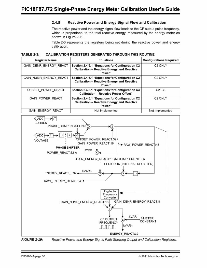
2.4.5 Reactive Power and Energy Signal Flow and CalibrationThe reactive power and the energy signal flow leads to the CF output pulse frequency,which is proportional to the total reactive energy, measured by the energy meter asshown in Figure 2-19. Table 2-3 represents the registers being set during the reactive power and energycalibration.
TABLE 2-3: CALIBRATION REGISTERS GENERATED THROUGH THIS ROUTINE
FIGURE 2-19: Reactive Power and Energy Signal Path Showing Output and Calibration Registers.
Register Name Equations Configurations Required
GAIN_DENR_ENERGY_REACT Section 2.4.6.1 “Equations for Configuration C2 Calibration – Reactive Energy and Reactive
Power”
C2 ONLY
GAIN_NUMR_ENERGY_REACT Section 2.4.6.1 “Equations for Configuration C2 Calibration – Reactive Energy and Reactive
Power”
C2 ONLY
OFFSET_POWER_REACT Section 2.4.8.1 “Equations for Configuration C3 Calibration – Reactive Power Offset”
C2, C3
GAIN_POWER_REACT Section 2.4.6.1 “Equations for Configuration C2 Calibration – Reactive Energy and Reactive
Power”
C2 ONLY
GAIN_ENERGY_REACT Not Implemented Not Implemented
X Σ
OFFSET_POWER_REACT:32Φ
PHASE_COMPENSATION:8
ADC
ADC
CURRENT
VOLTAGE
XkVAR
kVARhX
GAIN_POWER_REACT:16
GAIN_ENERGY_REACT:16 (NOT IMPLEMENTED)
ENERGY_REACT_L:32
POWER_REACT:32
RAW_ENERGY_REACT:64
RAW_POWER_REACT:48
X
PERIOD:16 (INTERNAL REGISTER)
Digital toFrequencyConverter
/
GAIN_NUMR_ENERGY_REACT:16 GAIN_DENR_ENERGY_REACT:8
CF OUTPUTFREQUENCY
ENERGY_REACT:32
Σ 1/METER CONSTANT
kVARh
kVARh
α+
PHASE SHIFTER
DS51964A-page 36 © 2011 Microchip Technology Inc.

Meter Calibration
2.4.6 Configuration C2 Flow Chart – Reactive Power and Energy
Begin Calibration
Put meter in Calibration Configuration C2
(VB and IB at PF=0.5 lag)
Set MODE1 register bits and LINE_CYC register
Enable Calibration Mode by setting bit 0 and 1 of CAL_CONTROL
register to 1
Is CAL_MODE
bit 1 low?
NO
YES
Read contents of RAW_ENERGY_REACT, RAW_POWER_REACT
Calculate and Write GAIN_NUMR_ENERGY_REACT GAIN_DENR_ENERGY_REACT, GAIN_POWER_REACT contents
based on equations in Section 2.4.6.1 “Equations for Con-figuration C2 Calibration – Reactive
Energy and Reactive Power”
End
© 2011 Microchip Technology Inc. DS51964A-page 37

PIC18F87J72 Single-Phase Energy Meter Calibration User’s Guide
2.4.6.1 EQUATIONS FOR CONFIGURATION C2 CALIBRATION – REACTIVE ENERGY AND REACTIVE POWER
Equations 2-18 to 2-22 represent the method for calculating the calibration and thecorrection factors after configuration C2. The PC calibration software processes thesecalculations automatically.Equations 2-18 to Equation 2-21 applies for calculating the proper output frequency ofthe CF output. See Section 2.4.6 “Configuration C2 Flow Chart – Reactive Powerand Energy” for the meter input conditions.
EQUATION 2-18:
EQUATION 2-19:
EQUATION 2-20:
Equations 2-21 and 2-22 are used for calculating the proper Gain/LSb registers incalibration.
EQUATION 2-21:
EQUATION 2-22:
Note: Convert to a 16-bit unsigned integer for compatibility with the energy meterregister and firmware calculations.
Note: Convert to a 16-bit unsigned integer for compatibility with the energy meter register and firmware calculations.
CF_IMP_S Meter Constant3600-------------------------------------
VBIB1000-------------⋅=
LINE_CYC_NUM 2LINE_CYC=
GAIN
232 CF_IMP_S SIN(60)⋅⋅Line Freq Samples per Cycle⋅--------------------------------------------------------------------------⎝ ⎠⎜ ⎟⎛ ⎞
RAW_ENERGY_REACTLINE_CYC_NUM 256⋅-----------------------------------------------------------⎝ ⎠⎛ ⎞
-------------------------------------------------------------------------------- 32768⋅=
If GAIN>65535
Then,
GAIN_NUMR_ENERGY_REACT = GAIN / 2
GAIN_DENR_ENERGY_REACT = GAIN_DENR_ENERGY_REACT + 1
else,
GAIN_NUMR_ENERGY_REACT = GAIN
GAIN_DENR_ENERGY_REACT = GAIN_DENR_ENERGY_REACT
PLSb = Value from Table 2-7 based on VB and IMAX values
GAIN_POWER_REACT
VB IB SIN(60)⋅⋅PLSb----------------------------------------------
⎝ ⎠⎜ ⎟⎛ ⎞
RAW_POWER_REACT64 LINE_CYC_NUM⋅---------------------------------------------------------⎝ ⎠⎛ ⎞-------------------------------------------------------------- 32768⋅=
DS51964A-page 38 © 2011 Microchip Technology Inc.
Meter Calibration
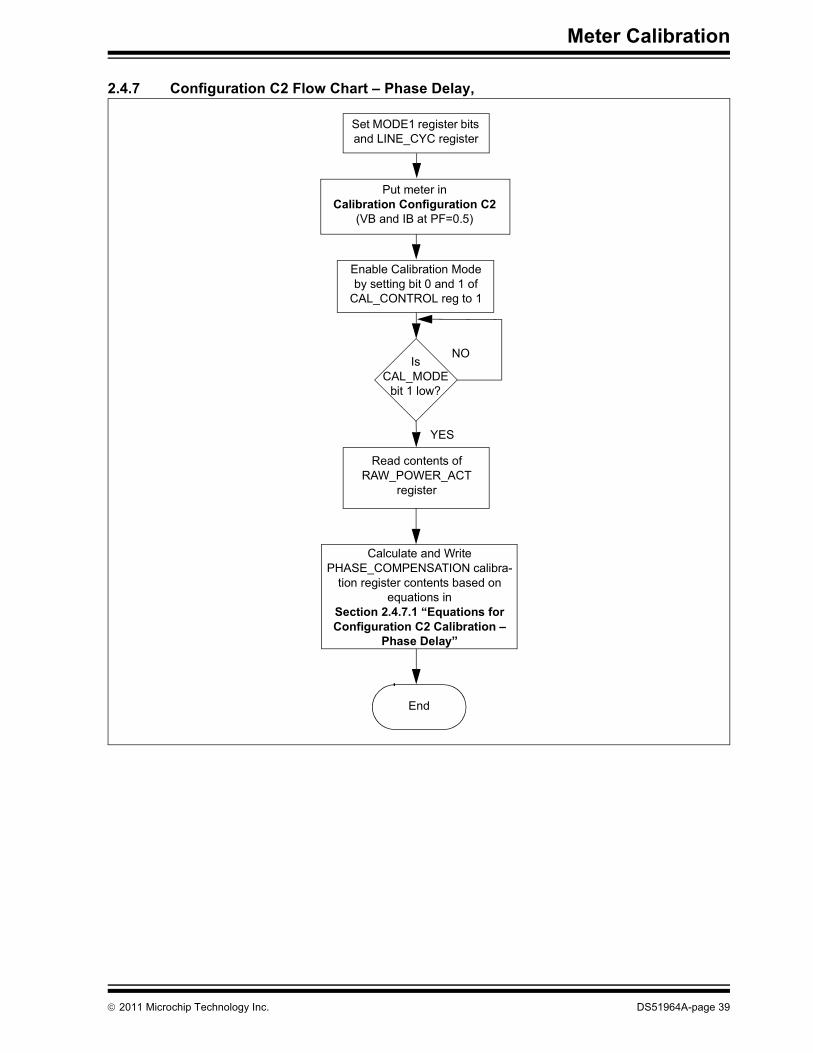
2.4.7 Configuration C2 Flow Chart – Phase Delay,
Put meter in Calibration Configuration C2
(VB and IB at PF=0.5)
Enable Calibration Mode by setting bit 0 and 1 of
CAL_CONTROL reg to 1
Is CAL_MODE
bit 1 low?
NO
YES
Calculate and Write PHASE_COMPENSATION calibra-
tion register contents based on equations in
Section 2.4.7.1 “Equations for Configuration C2 Calibration –
Phase Delay”
End
Read contents of RAW_POWER_ACT
register
Set MODE1 register bits and LINE_CYC register
© 2011 Microchip Technology Inc. DS51964A-page 39

PIC18F87J72 Single-Phase Energy Meter Calibration User’s Guide
2.4.7.1 EQUATIONS FOR CONFIGURATION C2 CALIBRATION – PHASE DELAY
For active power, Equations 2-23 to 2-27 are used to calculate the time shift delay for a given phase.
EQUATION 2-23:
EQUATION 2-24:
EQUATION 2-25:
EQUATION 2-26:
EQUATION 2-27:
Note 1: Convert to an 8-bit signed integer for compatibility with the energy meter register and firmware calculations.
2: Since the 60° (default) is being subtracted from the measured quantity,the current should lag the voltage under configuration C2.
3: In the reference design, with a sampling rate of 3906 samples/sec,Degree/Sample value will be equal to 5.529.
W1 RAW_POWER_ACT @ PF 1, Configuration C1= =
W2 RAW_POWER_ACT @ PF 0.5 Configuration C2,= =
LINE_CYC_NUM_1 LINE_CYC_NUM @ PF 1 Configuration C1,= =
LINE_CYC_NUM_2 LINE_CYC_NUM @ PF 0.5, Configuration C2= =
PHASE_COMPENSATION
COS 1– W2( ) LINE_CYC_NUM2( )⁄W1( ) LINE_CYC_NUM1( )⁄
----------------------------------------------------------------------⎝ ⎠⎛ ⎞ 180
PI---------⋅⎝ ⎠⎛ ⎞ 60–
DEGREESAMPLE-------------------------
-------------------------------------------------------------------------------------------------------------------------------------- 128⋅=
DS51964A-page 40 © 2011 Microchip Technology Inc.

Meter Calibration
2.4.8 Configuration C3 Flow Chart – Reactive Power Offset
Put meter in Calibration Configuration C3
(VB and 1/100 IB at PF = 0.5 lag)
Set MODE1 register bits and LINE_CYC register
(suggest 256 Line Cycles)
Enable Calibration Mode by setting bit 0 and 1 of
CAL_CONTROL register to 1
Is CAL_MODE
bit 1 low?
Read contents of RAW_POWER_REACT
Register
Calculate and Write OFFSET_POWER_REACT
register contents based on equations in Section 2.4.8.1 “Equations for Configuration C3 Calibration –
Reactive Power Offset”
NO
YES
End
© 2011 Microchip Technology Inc. DS51964A-page 41

PIC18F87J72 Single-Phase Energy Meter Calibration User’s Guide
2.4.8.1 EQUATIONS FOR CONFIGURATION C3 CALIBRATION – REACTIVE POWER OFFSET
For reactive power offset, Equations 2-28 to 2-32 apply for a given phase. W1 corre-sponds to the RAW_POWER_REACT register obtained during configuration C2.LINE_CYC_NUM_W1 corresponds to the LINE_CYC during this measurement. W2 corresponds to the RAW_POWER_REACT register obtained during configuration C3. LINE_CYC_NUM_W2 is the LINE_CYC during this measurement.
EQUATION 2-28:
EQUATION 2-29:
EQUATION 2-30:
EQUATION 2-31:
EQUATION 2-32:
The OFFSET_POWER_REACT registers hold a signed 32-bit value. However, themath in the microcontroller can overflow for some values near the limits. Limit checkthe resulting value to make sure the value is between -2,130,706,432 and2,130,706,431 (inclusive). Values less than -2,130,706,432 should be set to-2,130,706,432, while values greater than 2,130,706,431 should be set to2,130,706,431. If the value is limited, the user should be aware that the meter cannotcorrect the offset completely.It is expected that this value will always be negative. If the value is positive, it may indicate that the user has not provided a large enough number of line cycles for configuration C4 (where, the number of line cycles should be set to a larger value, such as 64 or 128). This may also be true if offset does not contribute a large enough percentage to W2 (for example, 10% to 50% or more).
Note: Convert to a 32-bit signed integer for compatibility with the energy meterregister and firmware calculations.
W1 RAW_POWER_REACT @ IB,Configuration C2=
W2 RAW_POWER_REACT @ 1/100 IB, Configuration C3=
LINE_CYC_NUM_W1 LINE_CYC_NUM in Configuration C2=
LINE_CYC_NUM_W2 LINE_CYC_NUM in Configuration C3=
OFFSET_POWER_REACT W1( ) 100( )⁄LINE_CYC_NUM_W1------------------------------------------------------ W2
LINE_CYC_NUM_W2------------------------------------------------------–=
DS51964A-page 42 © 2011 Microchip Technology Inc.

Meter Calibration
2.4.9 Configuration C4 Flow Chart - Active Power Offset
Put meter in Calibration Configuration C4
(VB and 1/100 IB at PF = 1)
Set MODE1 register bits and LINE_CYC register
(suggest 256 Line Cycles)
Enable Calibration Mode by setting bit 0 and 1 of
CAL_CONTROL register to 1
Is CAL_MODE
bit 1 low?
Read contents of RAW_ENERGY_ACT
Register
Calculate and Write OFFSET_POWER_ACT
register contents based on equa-tions in
Section 2.4.9.1 “Equations for Configuration C4 Calibration –
Active Power Offset”
NO
YES
End
© 2011 Microchip Technology Inc. DS51964A-page 43

PIC18F87J72 Single-Phase Energy Meter Calibration User’s Guide
2.4.9.1 EQUATIONS FOR CONFIGURATION C4 CALIBRATION – ACTIVE POWER OFFSET
For active power offset, Equations 2-33 to 2-37 apply for a given phase. W1 corre-sponds to the RAW_POWER_ACT register obtained during configuration C1.LINE_CYC_NUM_W1 corresponds to the LINE_CYC during this measurement. W2 corresponds to the RAW_POWER_ACT register obtained during configuration C4.LINE_CYC_NUM_W2 is the LINE_CYC during this measurement.
EQUATION 2-33:
EQUATION 2-34:
EQUATION 2-35:
EQUATION 2-36:
EQUATION 2-37:
The OFFSET_POWER_ACT registers hold a signed 32-bit value. However, the math in the microcontroller can overflow for some values near the limits. Limit check the resulting value to make sure the value is between -2,130,706,432 and 2,130,706,431 (inclusive). Values less than -2,130,706,432 should be set to -2,130,706,432, while values greater than 2,130,706,431 should be set to 2,130,706,431. If the value is limited, the user should be aware that the meter cannot correct the offset completely.It is expected that this value will always be negative. If the value is positive, it may indicate that the user has not provided a large enough number of line cycles for configuration C4 (where, the number of line cycles should be set to a larger value, such as 64 or 128). This may also be true if offset does not contribute a large enough percentage to W2 (for example, 10% to 50% or more).
Note: Convert to a 32-bit signed integer for compatibility with the energy meter register and firmware calculations.
W1 RAW_POWER_ACT @ IB,Configuration C1=
W2 RAW_POWER_ACT @ 1/100 IB, Configuration C4=
LINE_CYC_NUM_W1 LINE_CYC_NUM in Configuration C1=
LINE_CYC_NUM_W2 LINE_CYC_NUM in Configuration C4=
OFFSET_POWER_ACT W1( ) 100( )⁄LINE_CYC_NUM_W1------------------------------------------------------ W2
LINE_CYC_NUM_W2------------------------------------------------------–=
DS51964A-page 44 © 2011 Microchip Technology Inc.

Meter Calibration
2.4.10 Flow Chart for RMS Calibration
Put meter in Calibration Configuration C5
(VB and 1/10 IB at PF = 1)
End
Is CAL_MODE
bit 1 low?
Read contents of RAW2_I_RMS and
RAW2_V_RMS registers (referred to as IR2 and VR2
in equation set)
NO
YES
Calculate and Write OFFSET_I_RMS, OFFSET_V_RMS, GAIN_I_RMS, GAIN_V_RMS, calibration register
contents based equations in Section 2.4.10.1 “Equations for Config-uration C5 Calibration – RMS Voltage
and Current”
Fetch values from Calibration Configuration C1
Set MODE1 register bits and LINE_CYC register
© 2011 Microchip Technology Inc. DS51964A-page 45
PIC18F87J72 Single-Phase Energy Meter Calibration User’s Guide
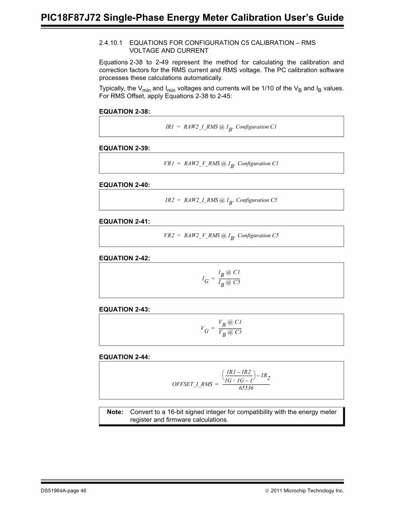
2.4.10.1 EQUATIONS FOR CONFIGURATION C5 CALIBRATION – RMS VOLTAGE AND CURRENT
Equations 2-38 to 2-49 represent the method for calculating the calibration andcorrection factors for the RMS current and RMS voltage. The PC calibration softwareprocesses these calculations automatically.Typically, the Vmin and Imin voltages and currents will be 1/10 of the VB and IB values.For RMS Offset, apply Equations 2-38 to 2-45:
EQUATION 2-38:
EQUATION 2-39:
EQUATION 2-40:
EQUATION 2-41:
EQUATION 2-42:
EQUATION 2-43:
EQUATION 2-44:
Note: Convert to a 16-bit signed integer for compatibility with the energy meter register and firmware calculations.
IR1 RAW2_I_RMS @ IB, Configuration C1=
VR1 RAW2_V_RMS @ IB, Configuration C1=
IR2 RAW2_I_RMS @ IB, Configuration C5=
VR2 RAW2_V_RMS @ IB, Configuration C5=
IGIB @ C1
IB @ C5----------------------=
VGVB @ C1
VB @ C5------------------------=
OFFSET_I_RMS
IR1 IR2–IG IG 1–⋅----------------------------⎝ ⎠⎛ ⎞ IR2–
65536-------------------------------------------------=
DS51964A-page 46 © 2011 Microchip Technology Inc.
Meter Calibration
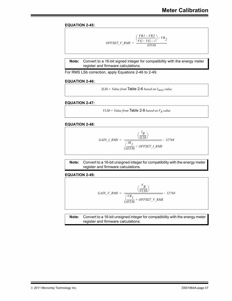
EQUATION 2-45:
For RMS LSb correction, apply Equations 2-46 to 2-49.
EQUATION 2-46:
EQUATION 2-47:
EQUATION 2-48:
EQUATION 2-49:
Note: Convert to a 16-bit signed integer for compatibility with the energy meter register and firmware calculations.
Note: Convert to a 16-bit unsigned integer for compatibility with the energy meter register and firmware calculations.
Note: Convert to a 16-bit unsigned integer for compatibility with the energy meter register and firmware calculations.
OFFSET_V_RMS
VR1 VR2–VG VG 1–⋅-------------------------------⎝ ⎠⎛ ⎞ VR2–
65536------------------------------------------------------=
ILSb = Value from Table 2-6 based on IMAX value
VLSb = Value from Table 2-8 based on VB value
GAIN_I_RMS
IBILSb------------⎝ ⎠⎛ ⎞
IR165536--------------- OFFSET_I_RMS+
------------------------------------------------------------------- 32768⋅=
GAIN_V_RMS
VBVLSb--------------⎝ ⎠⎛ ⎞
VR165536--------------- OFFSET_V_RMS+
--------------------------------------------------------------------- 32768⋅=
© 2011 Microchip Technology Inc. DS51964A-page 47

PIC18F87J72 Single-Phase Energy Meter Calibration User’s Guide
2.5 SINGLE POINT CALIBRATIONSingle Point Calibration is a subset of multipoint calibration, with the omission of a fewcalibration register value calculations. With the omission, the number of stages in cali-bration are reduced, thus speeding the calibration process. Single Point Calibration canbe carried out if the meter accuracy class is achieved, even with the omission of a fewcalibration parameter calculations, such as offset.Single Point Calibration includes only two stages of calibration, as listed below:1. Calibration Stage C1: Active power, energy and RMS voltage, current gain
calibration, gain - basic voltage VB and basic current IB at a power factor of unity.For example, 220V and 5A at PF = 1.0.
The calibration parameters calculated in this stage include:
TABLE 2-4: CALIBRATION REGISTERS GENERATED THROUGH THIS ROUTINE
2. Calibration Stage C2: Phase compensation and reactive power and energy gain calibration - basic 220V and 5A voltage VB and basic current IB at a power factor of 0.5 lag.
The calibration parameters calculated in this stage include:
TABLE 2-5: CALIBRATION REGISTERS GENERATED THROUGH THIS ROUTINE
Register Name Equations Configurations Required
GAIN_POWER_ACT Section 2.4.4.1 “Equations for Configuration C1 Calibration – Active Energy and Active Power”
C1 ONLY
GAIN_NUMR_ENERGY_ACT Section 2.4.4.1 “Equations for Configuration C1 Calibration – Active Energy and Active Power”
C1 ONLY
GAIN_DENT_ENERGY_ACT Section 2.4.4.1 “Equations for Configuration C1 Calibration – Active Energy and Active Power”
C1 ONLY
GAIN_V_RMS Section 2.4.10.1 “Equations for Configuration C5 Calibration – RMS Voltage and Current”
C1 ONLY
GAIN_I_RMS Section 2.4.10.1 “Equations for Configuration C5 Calibration – RMS Voltage and Current”
C1 ONLY
Register Name Equations Configurations Required
GAIN_POWER_REACT Section 2.4.6.1 “Equations for Configura-tion C2 Calibration – Reactive Energy and
Reactive Power”
C2 ONLY
GAIN_NUMR_ENERGY_REACT Section 2.4.6.1 “Equations for Configura-tion C2 Calibration – Reactive Energy and
Reactive Power”
C2 ONLY
GAIN_DENT_ENERGY_REACT Section 2.4.6.1 “Equations for Configura-tion C2 Calibration – Reactive Energy and
Reactive Power”
C2 ONLY
DS51964A-page 48 © 2011 Microchip Technology Inc.

Meter Calibration
2.6 CREEP THRESHOLD CALIBRATIONCreep threshold represents a state below which the energy accumulation will be sup-pressed. Due to external noise, even under No Load condition, the meter may register avery small value of energy. To inhibit registering of this unwanted energy, the meter needsto be calibrated for creep threshold. Creep Threshold Calibration also accounts for thethreshold starting current, above which the energy needs to be registered. In Creep Threshold Calibration, maximum-rated operational voltage, threshold startingcurrent and Meter Constant of the meter are used to compute the creep threshold timervalue. Using these parameters, the time for energy accumulation equivalent to1/METER CONSTANT at threshold starting current, is calculated. If the energyaccumulation is less than 1/METER CONSTANT during this creep threshold time, itrepresents either a No Load condition, or load current less than the threshold startingcurrent. In such a case, the incremental energy accumulation will be flushed, suppressingenergy accumulation.
2.6.1 Creep Threshold ComputationTo accumulate energy equal to 1/METER CONSTANT at the above specified line input, time taken is as shown in Equation 2-50.
EQUATION 2-50:
2.6.2 Creep Threshold Calibration procedureApply the following procedure for Creep Threshold Calibration:1. Enter the maximum rated voltage of the meter in “Maximum Input Voltage (V)”
field, as shown in Figure 2-20.2. Enter the least detectable current the of meter in “Starting Current”.3. Set the “Meter Constant”.4. Click Save to EEPROM to save the calibration data to EEPROM. During this
process, creep threshold values get computed and saved in the meter.
Note: Creep Threshold Calibration needs to be done irrespective of the type of above mentioned calibration process.
Time 1kWh( ) METERCONSTANT MAX_VOLTAGE LEAST_CURRENT_DETECT⋅ ⋅( )⁄=
Time is converted to equivalent minutes + secondsCREEP_THRESHOLD_MINUTE = Creep Threshold time in minutes CREEP_THRESHOLD_SECOND = Creep Threshold time in seconds
© 2011 Microchip Technology Inc. DS51964A-page 49

PIC18F87J72 Single-Phase Energy Meter Calibration User’s Guide
FIGURE 2-20: Creep Threshold Calibration.
DS51964A-page 50 © 2011 Microchip Technology Inc.
Meter Calibration
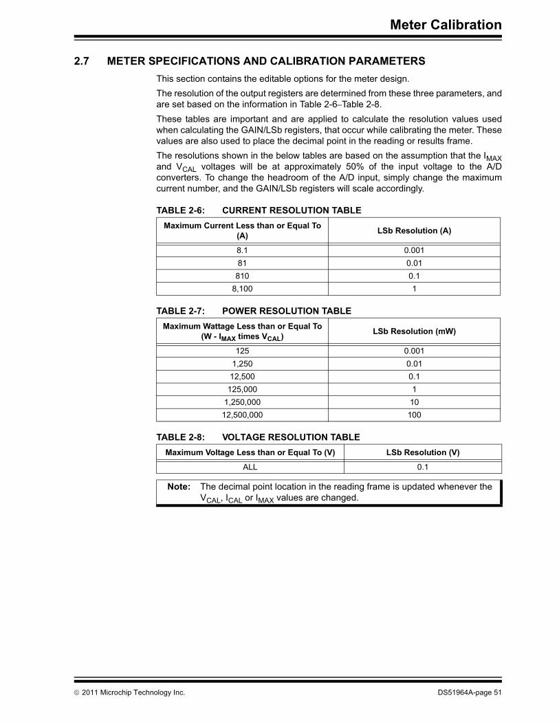
2.7 METER SPECIFICATIONS AND CALIBRATION PARAMETERSThis section contains the editable options for the meter design. The resolution of the output registers are determined from these three parameters, andare set based on the information in Table 2-6–Table 2-8.These tables are important and are applied to calculate the resolution values usedwhen calculating the GAIN/LSb registers, that occur while calibrating the meter. Thesevalues are also used to place the decimal point in the reading or results frame.The resolutions shown in the below tables are based on the assumption that the IMAXand VCAL voltages will be at approximately 50% of the input voltage to the A/Dconverters. To change the headroom of the A/D input, simply change the maximumcurrent number, and the GAIN/LSb registers will scale accordingly.
TABLE 2-6: CURRENT RESOLUTION TABLE
TABLE 2-7: POWER RESOLUTION TABLE
TABLE 2-8: VOLTAGE RESOLUTION TABLE
Maximum Current Less than or Equal To (A) LSb Resolution (A)
8.1 0.00181 0.01
810 0.18,100 1
Maximum Wattage Less than or Equal To (W - IMAX times VCAL) LSb Resolution (mW)
125 0.0011,250 0.01
12,500 0.1125,000 1
1,250,000 1012,500,000 100
Maximum Voltage Less than or Equal To (V) LSb Resolution (V)
ALL 0.1
Note: The decimal point location in the reading frame is updated whenever the VCAL, ICAL or IMAX values are changed.
© 2011 Microchip Technology Inc. DS51964A-page 51

PIC18F87J72 Single-Phase Energy Meter Calibration User’s Guide
DS51964A-page 52 © 2011 Microchip Technology Inc.

PIC18F87J72 SINGLE-PHASEENERGY METER CALIBRATION
USER’S GUIDE
Chapter 3. Microchip Energy Meter Software
3.1 INTRODUCTIONThe energy meter software is a Graphical User interface (GUI) that enables the meter to be monitored and debugged in the development phase. It also provides the calibration tool used to precisely calibrate the meter.
3.2 MAIN SCREENThe main screen contains four tabs:• Energy Meter: This tab contains the instantaneous meter output display and a
debug window, which enables access to all the internal registers of the meter.• Meter Parameters: This tab contains a calibration tool for Multipoint and Single
Point Calibration.• Power Calibration: This tab is used for feedback calibration of voltage, current
and power. • Energy Calibration: This tab is used for feedback calibration of energy.The COM port selection option on top of the window is used to select a serial port or aserial port emulator. The status of the meter connection with the computer is displayed at the top of the win-dow. This status displays the text “Meter Detected” in green if connected, and changesits status to “Meter Disconnected” in red, if disconnected. This status is present acrossall the tabs. The tool has a feature to display the “Instantaneous Parameters”, updated in real time(see Figure 3-1).
© 2011 Microchip Technology Inc. DS51964A-page 53

PIC18F87J72 Single-Phase Energy Meter Calibration User’s Guide
FIGURE 3-1: Main Screen with Active Results Frame.
The “Instantaneous Parameters” field contains the recent meter output parameters,such as Active Power, Reactive Power, Apparent Power, RMS Current, RMS Voltageand Frequency. The registers in this frame are continuously collected and refreshed onthe PC side periodically.Table 3-1 shows examples of the meter readings.
TABLE 3-1: REGISTERS READINGS OF THE METERMeter Reading Register Example
Active Power POWER_ACT 101.44WReactive Power POWER_REACT 17.2371 VARApparent Power POWER_APP 102.894 VARMS Current Phase A I_RMS 0.45ARMS Voltage Phase A V_RMS 220.6VFrequency FREQUENCY 50 Hz
DS51964A-page 54 © 2011 Microchip Technology Inc.

Microchip Energy Meter Software
3.2.1 Decimal Point LocationThe location of the decimal point, i.e., the resolution of the power quantities, isdetermined by the values introduced in the “Calibration Parameters” field on theCalibration tab. When the meter is calibrated using the calibration methods availablewith this software, the proper GAIN/LSb correction factor is calculated to ensure theLeast Significant bit (LSb), which represents the least significant digit for a givenquantity. For example, if the PHA_I_RMS register, which represents the RMS current,contains the decimal value 4523, and the ILSb is defined to be 0.01 based on the meterdesign entry, this value represents exactly 45.23A.Another example for active power is shown in Table 3-1, where the POWER_ACT register contains the value 101.44. For this example, the power resolution is 0.1 mW. Therefore, this register represents exactly 101.44W.
© 2011 Microchip Technology Inc. DS51964A-page 55

PIC18F87J72 Single-Phase Energy Meter Calibration User’s Guide
3.3 DEBUG MODEThe Debug mode feature enables access to all the internal registers of the meter. Fromthe Energy Meter tab, click on Enter Debug Mode on the lower right corner of the tool.The Debug mode screen appears as shown in Figure 3-2.Debug mode displays a complete list of all the internal registers of the meter with theiraddress, name, attribute, register length and value.Each register is available for read and write in real time, when the meter is computing.This is a convenient tool for debugging operations, giving complete access to allinternal details of the meter.
3.3.1 Monitoring Individual RegistersThe tool enables the selected registers to be monitored for their real-time updates.Monitoring can be enabled by writing “1” to column “Monitor” across a particular regis-ter, as shown in Figure 3-2. By enabling this, the GUI reads the register periodically bybringing the real-time status. Unless monitoring is enabled, the register status is notupdated with every instantaneous refresh.
FIGURE 3-2: Debug Mode in Main Screen Showing Internal Registers.
DS51964A-page 56 © 2011 Microchip Technology Inc.

Microchip Energy Meter Software
3.3.2 Refreshing Registers StatusTo update all the internal registers, click Refresh Meter Registers at the lower rightcorner, as shown in Figure 3-2. However, this will update the registers only once perclick.
3.3.3 Writing to Individual RegistersIt is possible to write to individual registers for testing certain limiting conditions and finetuning the calibration registers. To write to a register, enter the value in hex format (asstored in the registers) in the “Value” column across that particular register, as shownin Figure 3-2, and press Enter to initiate the write process.
Note: “Value” and “Monitor” are the only two user editable columns. The remaining sections are read only.
© 2011 Microchip Technology Inc. DS51964A-page 57

PIC18F87J72 Single-Phase Energy Meter Calibration User’s Guide
NOTES:
DS51964A-page 58 © 2011 Microchip Technology Inc.

PIC18F87J72 SINGLE-PHASEENERGY METER CALIBRATION
USER’S GUIDE
Chapter 4. Communication Protocol
4.1 PROTOCOLThe Universal Asynchronous Receiver and Transmitter (UART) of the PICMicrocontroller is used to communicate with the meter. In addition to the reading andwriting of the registers, there are also dedicated commands for clearing, loading andstoring calibration registers to Flash. The first byte UART data is an ASCII characterthat represents the command, and each command has a specific protocol. Eachcommand ends with the ASCII character “X”.
4.1.1 Command DescriptionThe first byte of the data (byte 0) is an ASCII character E, L, S, W and R. • E – Request for Echo Response to which meter responds with “Q” as
acknowledgment• L – Load Calibration Registers from Flash (LOAD)• S – Store Calibration Registers (STORE)• W – Write Bytes (WRITE)• R – Read Bytes (READ)• C – Load Default Calibration ValuesThe last data byte is always an ‘X’ character. All commands will result in the same com-mand being returned. The exception is the ‘R’ (READ) command which will return theadditional data in lieu of the number of bytes.
4.1.1.1 “E” ECHO: - TO DETECT THE METER CONNECTION
Example: ‘EX’.Returns: ‘QX’
4.1.1.2 “L” LOAD: LOAD CALIBRATION REGISTERS FROM FLASH
Example: ‘LX’.Returns: ‘LX’. This command is used to verify that the calibration values were actually written intoflash (or EEPROM). When the software executes a ‘SX’ command, it should verify thatthe values were stored by issuing a ‘LX’ command and then reading the calibrationvalues with an ‘R’ command.
4.1.1.3 “S” STORE: STORE CALIBRATION REGISTERS INTO FLASH
The Store command writes all the calibration values to the internal EEPROM, and thisfunction takes some time. During that time, the meter is not functional. The Storecommand should only be used after calibrating the meter, not while it is in actual use.Example: ‘SX’. Returns: ‘SX’.
© 2011 Microchip Technology Inc. DS51964A-page 59
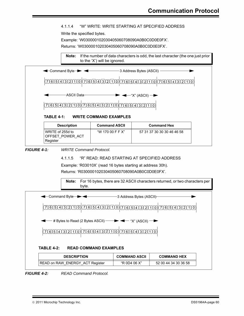
Communication Protocol
4.1.1.4 “W” WRITE: WRITE STARTING AT SPECIFIED ADDRESS
Write the specified bytes.Example: ‘W030000102030405060708090A0B0C0D0E0FX’.Returns: ‘W030000102030405060708090A0B0C0D0E0FX’.
FIGURE 4-1: WRITE Command Protocol.
4.1.1.5 “R” READ: READ STARTING AT SPECIFIED ADDRESS
Example: ‘R03010X’ (read 16 bytes starting at address 30h). Returns: ‘R030000102030405060708090A0B0C0D0E0FX’.
FIGURE 4-2: READ Command Protocol.
Note: If the number of data characters is odd, the last character (the one just prior to the ‘X’) will be ignored.
Command Byte
7 6 5 4 3 2 1 0
3 Address Bytes (ASCII)
7 6 5 4 3 2 1 0 7 6 5 4 3 2 1 07 6 5 4 3 2 1 0
7 6 5 4 3 2 1 0 7 6 5 4 3 2 1 0
ASCII Data
TABLE 4-1: WRITE COMMAND EXAMPLES
Description Command ASCII Command Hex
WRITE of 255d to OFFSET_POWER_ACT Register
“W 170 00 F F X” 57 31 37 30 30 30 46 46 58
“X” (ASCII)
7 6 5 4 3 2 1 0
Note: For 16 bytes, there are 32 ASCII characters returned, or two characters per byte.
Command Byte
7 6 5 4 3 2 1 0
3 Address Bytes (ASCII)
7 6 5 4 3 2 1 0 7 6 5 4 3 2 1 07 6 5 4 3 2 1 0
7 6 5 4 3 2 1 0
# Bytes to Read (2 Bytes ASCII)
7 6 5 4 3 2 1 07 6 5 4 3 2 1 0
“X” (ASCII)
TABLE 4-2: READ COMMAND EXAMPLES
DESCRIPTION COMMAND ASCII COMMAND HEX
READ on RAW_ENERGY_ACT Register “R 0D4 06 X” 52 00 44 34 30 36 58
© 2011 Microchip Technology Inc. DS51964A-page 60
Communication Protocol
NOTES:
© 2011 Microchip Technology Inc. DS51964A-page 61

DS51964A-page 62 © 2011 Microchip Technology Inc.
AMERICASCorporate Office2355 West Chandler Blvd.Chandler, AZ 85224-6199Tel: 480-792-7200 Fax: 480-792-7277Technical Support: http://www.microchip.com/supportWeb Address: www.microchip.comAtlantaDuluth, GA Tel: 678-957-9614 Fax: 678-957-1455BostonWestborough, MA Tel: 774-760-0087 Fax: 774-760-0088ChicagoItasca, IL Tel: 630-285-0071 Fax: 630-285-0075ClevelandIndependence, OH Tel: 216-447-0464 Fax: 216-447-0643DallasAddison, TX Tel: 972-818-7423 Fax: 972-818-2924DetroitFarmington Hills, MI Tel: 248-538-2250Fax: 248-538-2260IndianapolisNoblesville, IN Tel: 317-773-8323Fax: 317-773-5453Los AngelesMission Viejo, CA Tel: 949-462-9523 Fax: 949-462-9608Santa ClaraSanta Clara, CA Tel: 408-961-6444Fax: 408-961-6445TorontoMississauga, Ontario, CanadaTel: 905-673-0699 Fax: 905-673-6509
ASIA/PACIFICAsia Pacific OfficeSuites 3707-14, 37th FloorTower 6, The GatewayHarbour City, KowloonHong KongTel: 852-2401-1200Fax: 852-2401-3431Australia - SydneyTel: 61-2-9868-6733Fax: 61-2-9868-6755China - BeijingTel: 86-10-8569-7000 Fax: 86-10-8528-2104China - ChengduTel: 86-28-8665-5511Fax: 86-28-8665-7889China - ChongqingTel: 86-23-8980-9588Fax: 86-23-8980-9500China - HangzhouTel: 86-571-2819-3180 Fax: 86-571-2819-3189China - Hong Kong SARTel: 852-2401-1200 Fax: 852-2401-3431China - NanjingTel: 86-25-8473-2460Fax: 86-25-8473-2470China - QingdaoTel: 86-532-8502-7355Fax: 86-532-8502-7205China - ShanghaiTel: 86-21-5407-5533 Fax: 86-21-5407-5066China - ShenyangTel: 86-24-2334-2829Fax: 86-24-2334-2393China - ShenzhenTel: 86-755-8203-2660 Fax: 86-755-8203-1760China - WuhanTel: 86-27-5980-5300Fax: 86-27-5980-5118China - XianTel: 86-29-8833-7252Fax: 86-29-8833-7256China - XiamenTel: 86-592-2388138 Fax: 86-592-2388130China - ZhuhaiTel: 86-756-3210040 Fax: 86-756-3210049
ASIA/PACIFICIndia - BangaloreTel: 91-80-3090-4444 Fax: 91-80-3090-4123India - New DelhiTel: 91-11-4160-8631Fax: 91-11-4160-8632India - PuneTel: 91-20-2566-1512Fax: 91-20-2566-1513Japan - YokohamaTel: 81-45-471- 6166 Fax: 81-45-471-6122Korea - DaeguTel: 82-53-744-4301Fax: 82-53-744-4302Korea - SeoulTel: 82-2-554-7200Fax: 82-2-558-5932 or 82-2-558-5934Malaysia - Kuala LumpurTel: 60-3-6201-9857Fax: 60-3-6201-9859Malaysia - PenangTel: 60-4-227-8870Fax: 60-4-227-4068Philippines - ManilaTel: 63-2-634-9065Fax: 63-2-634-9069SingaporeTel: 65-6334-8870Fax: 65-6334-8850Taiwan - Hsin ChuTel: 886-3-6578-300Fax: 886-3-6578-370Taiwan - KaohsiungTel: 886-7-213-7830Fax: 886-7-330-9305Taiwan - TaipeiTel: 886-2-2500-6610 Fax: 886-2-2508-0102Thailand - BangkokTel: 66-2-694-1351Fax: 66-2-694-1350
EUROPEAustria - WelsTel: 43-7242-2244-39Fax: 43-7242-2244-393Denmark - CopenhagenTel: 45-4450-2828 Fax: 45-4485-2829France - ParisTel: 33-1-69-53-63-20 Fax: 33-1-69-30-90-79Germany - MunichTel: 49-89-627-144-0 Fax: 49-89-627-144-44Italy - Milan Tel: 39-0331-742611 Fax: 39-0331-466781Netherlands - DrunenTel: 31-416-690399 Fax: 31-416-690340Spain - MadridTel: 34-91-708-08-90Fax: 34-91-708-08-91UK - WokinghamTel: 44-118-921-5869Fax: 44-118-921-5820
Worldwide Sales and Service
05/02/11