Pi-SPROG 3 DCC Decoder Programmer and Command Station for ...
33
Pi-SPROG 3 User Guide 1 Draft 0.6 July 2020 © Copyright 2020 SPROG DCC Pi-SPROG 3 DCC Decoder Programmer and Command Station for Raspberry Pi User Guide
Transcript of Pi-SPROG 3 DCC Decoder Programmer and Command Station for ...
Pi-SPROG 3 User Guide 1
Draft 0.6 July 2020 © Copyright 2020 SPROG DCC
Pi-SPROG 3
DCC Decoder Programmer and Command Station for Raspberry Pi
User Guide

Pi-SPROG 3 User Guide 2
Draft 0.6 July 2020 © Copyright 2020 SPROG DCC
Revision History ............................................................................. 4
Introduction ..................................................................................... 5
Requirements ............................................................................... 5
Features ........................................................................................ 5
Specification/Operating Conditions .......................................... 6
Getting Started ................................................................................ 7
Install the Operating System ...................................................... 7
Connect the Pi-SPROG 3 to your Raspberry Pi ........................ 7
Connect the Raspberry Pi Power Supply .................................. 8
Connect the Pi-SPROG 3 Power Supply ................................... 8
Connect an Optional Track Activity LED .................................. 8
Connect the Programming Track or Layout ............................. 9
Connecting an Additional Booster ............................................ 9
Accessing the Raspberry Pi Desktop ........................................ 9
GPIO Pass-Through Connector ............................................... 10
The SPROG DCC Generation 5 Interface ................................ 11
Getting Started with JMRI (DecoderPro and PanelPro) ............ 11
Setting the Connection Preferences ........................................... 12
Introduction to Service Mode Programming with DecoderPro 12
Getting Started With PanelPro .................................................... 20
Programming with PanelPro .................................................... 21
Turnout Tables ........................................................................... 21
Power Control ............................................................................ 23
Panels ......................................................................................... 23
JMRI Tools ..................................................................................... 23
JMRI Throttles ............................................................................ 23
Connecting Throttle Devices to the Raspberry Pi Access

Pi-SPROG 3 User Guide 3
Draft 0.6 July 2020 © Copyright 2020 SPROG DCC
Point ............................................................................................ 25
SPROG DCC Generation 5 Tools ................................................ 25
Console ...................................................................................... 25
The Node Manager .................................................................... 25
The Command Station Monitor ................................................ 28
Mode Switcher ........................................................................... 28
Track Current and Track Voltage ............................................. 29
Pi-SPROG 3 Firmware Updates ................................................ 30
The JMRI System console ........................................................ 32
Known Issues at time of writing .................................................. 33
Troubleshooting ........................................................................... 33
Useful Links .................................................................................. 33
Pi-SPROG 3 User Guide 4
Draft 0.6 July 2020 © Copyright 2020 SPROG DCC
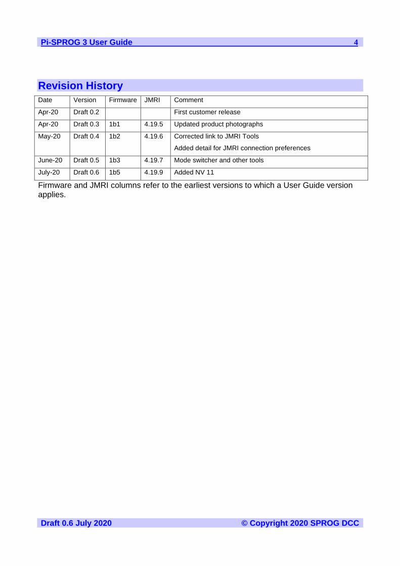
Revision History
Date Version Firmware JMRI Comment
Apr-20 Draft 0.2 First customer release
Apr-20 Draft 0.3 1b1 4.19.5 Updated product photographs
May-20 Draft 0.4 1b2 4.19.6 Corrected link to JMRI Tools
Added detail for JMRI connection preferences
June-20 Draft 0.5 1b3 4.19.7 Mode switcher and other tools
July-20 Draft 0.6 1b5 4.19.9 Added NV 11
Firmware and JMRI columns refer to the earliest versions to which a User Guide version applies.

Pi-SPROG 3 User Guide 5
Draft 0.6 July 2020 © Copyright 2020 SPROG DCC
Introduction
Pi-SPROG 3 is a DCC decoder programmer and command station for connection to a raspberry Pi single board computer. Pi-SPROG 3 is supported by DecoderPro and PanelPro, both part of the JMRI project (http://jmri.sourceforge.net/).
Pi-SPROG 3 can supply up to 2.5A to the layout with a track voltage of 12 – 18 V recommended.
The additional booster connector is no longer supported on current hardware.
Pi-SPROG 3 is based on same hardware as the orginal Pi-SPROG One with a completely re-written firmware. Pi-SPROG One owners should contact us for instructions on how to upgrade their firmware.
Requirements
• Raspberry Pi
• R-Pi 3 model B+ or R-Pi 4 model B 2GB recommended
• Raspberry Pi power supply
• Operating system and software on SD card
• Regulated DC Power Supply for Pi-SPROG 3 (see Table 1)
Features
• Programs virtually all NMRA compliant DCC decoders
• No extra hardware required for programming sound decoders (e.g. QSI, Soundtraxx)
• Easy to use graphical interface with DecoderPro
• Solder pads for optional track power activity LED
• Supports WiThrottle and EngineDriver Android apps, e.g.
• Pi 4 Model B using on-board WiFi
• Pi 3 Model B/B+ using on-board WiFi
• Pi 2 Model B with WiFi adapter
• Pi 2 Model B via wired network connection to wireless router
Pi-SPROG 3 User Guide 6
Draft 0.6 July 2020 © Copyright 2020 SPROG DCC
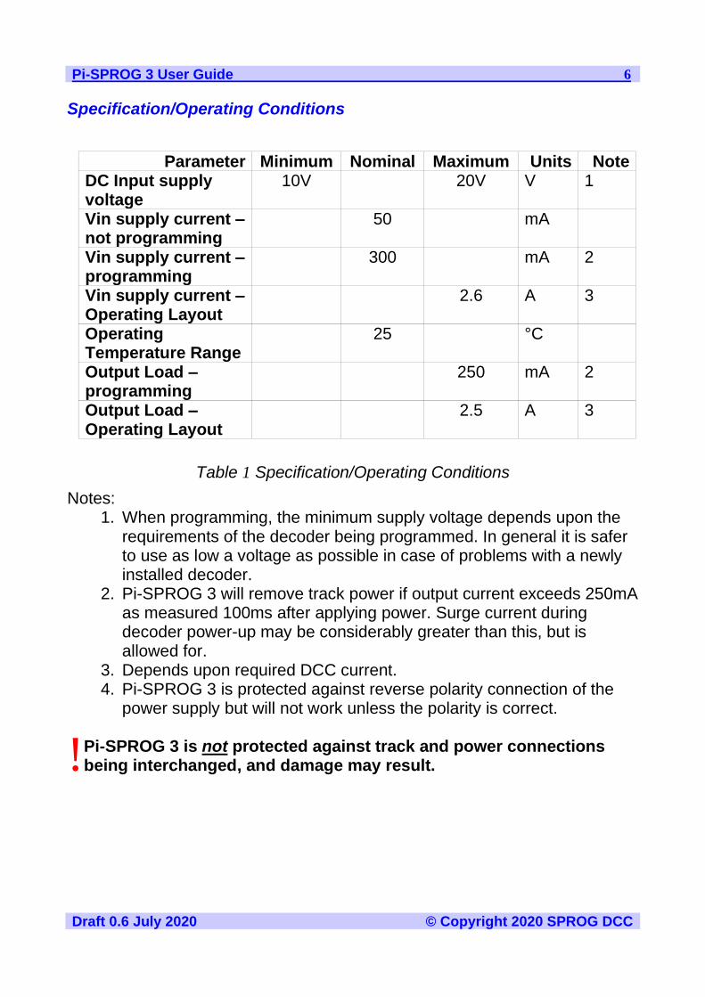
Specification/Operating Conditions
Parameter Minimum Nominal Maximum Units Note DC Input supply voltage
10V 20V V 1
Vin supply current – not programming
50 mA
Vin supply current –programming
300 mA 2
Vin supply current – Operating Layout
2.6 A 3
Operating Temperature Range
25 °C
Output Load – programming
250 mA 2
Output Load – Operating Layout
2.5 A 3
Table 1 Specification/Operating Conditions
Notes: 1. When programming, the minimum supply voltage depends upon the
requirements of the decoder being programmed. In general it is safer to use as low a voltage as possible in case of problems with a newly installed decoder.
2. Pi-SPROG 3 will remove track power if output current exceeds 250mA as measured 100ms after applying power. Surge current during decoder power-up may be considerably greater than this, but is allowed for.
3. Depends upon required DCC current. 4. Pi-SPROG 3 is protected against reverse polarity connection of the
power supply but will not work unless the polarity is correct.
Pi-SPROG 3 is not protected against track and power connections being interchanged, and damage may result.
!

Pi-SPROG 3 User Guide 7
Draft 0.6 July 2020 © Copyright 2020 SPROG DCC
Getting Started
The following steps are required to install Pi-SPROG 3 before you can use it for the first time:
Install the Operating System
Create an SD card image of the Raspberry Pi operating system and required software for your chosen application. Instructions for this are available from the SPROG DCC website download page:
SPROG DCC download page
You can follow the instructions to create your image, or purchase a pre-configured SD card from SPROG DCC.
It is strongly recommended that you make a backup of your SD card, using a tool such as win32diskimager
Connect the Pi-SPROG 3 to your Raspberry Pi
Always shutdown the Raspberry Pi and remove the power connection before connecting or disconnecting the Pi-SPROG 3.
The Pi-SPROG 3 should be plugged onto the 40 pin GPIO header, being careful to align the pins correctly. Using the plastic standoffs supplied with the Pi-SPROG 3 will ensure the correct alignment.
If you wish to remove the Pi-SPROG 3, do so carefully to avoid bending the connector pins on the Raspberry Pi.

Pi-SPROG 3 User Guide 8
Draft 0.6 July 2020 © Copyright 2020 SPROG DCC
Connect the Raspberry Pi Power Supply
Use a suitable power supply appropriate for your Raspberry Pi and any peripherals that may be attached and powered from the USB ports.
Connect the Pi-SPROG 3 Power Supply
Power supplies packaged with a Pi-SPROG 3 are already connected to the green pluggable terminal block.
For any other supply used (which must be a regulated DC power supply), connect as described below.
• Cut off the low voltage DC plug
• Separate the two conductors for about 3cm
• Strip 6-8mm of insulation from each conductor and twist the copper cores of each conductor together
• Insert the positive conductor into the +V terminal of the connector block and tighten the screw
• Insert the other conductor in the 0V terminal and tighten the screw
Pi-SPROG 3 is protected against reverse polarity connection of the power supply but will not work unless the polarity is correct.
Connect an Optional Track Activity LED
You may connect an optional track activity LED (requires soldering) to the two
Power
Connection
Track
Connection
Track
Activity LED
Connection
Pi-SPROG 3 User Guide 9
Draft 0.6 July 2020 © Copyright 2020 SPROG DCC
holes shown in the annotated picture. A current limit resistor is included on the PCB suitable for a standard red LED. The LED anode should be connected to the square pad.
The LED will illuminate steadily when the DCC power is connected.
The LED will flash slowly hen the track power is turned on, quickly when an overload is detected.
The LED is not provided by default as we felt some users may wish to mount their Pi-SPROG 3 in an inaccessible location and mount a remote LED on a front panel.
Connect the Programming Track or Layout
When using Pi-SPROG 3 as a programmer, the programming track MUST be isolated from all other DC or DCC control systems and connected only to the Pi-SPROG 3. Damage may result to the Pi-
SPROG 3 or other equipment if this rule is not followed. Connect the Pi-SPROG 3 to the programming track using the Trk A and Trk B terminals of the pluggable terminal block. There is no requirement to observe any particular polarity when connecting the programming track. The DCC output voltage will be approximately 1V below the power supply voltage, typically about 11V with the standard power supply provided.. During programming the track current is sensed 100 milliseconds after the programming track is powered up. If the current exceeds 250 milliAmps then the programming track power is removed to avoid potential damage to an incorrectly installed decoder.
Connecting an Additional Booster
The low power booster connection is not currently available. Some boosters can, however, be connected directly to the track output.
Accessing the Raspberry Pi Desktop
We recommend using remote access software from a host PC or other suitable device. SPROG DCC software images are pre-configured to disable the default desktop and run VNC server.
We recommend VNC viewer, or similar, on your PC. The server name for a SPROG DCC SD card is sprog-pi3 (pre 2020-02-13 SD card) or sprog-pi4 (2020-02-13 SD card or later). If you created your own SD card then use
!
Pi-SPROG 3 User Guide 10
Draft 0.6 July 2020 © Copyright 2020 SPROG DCC
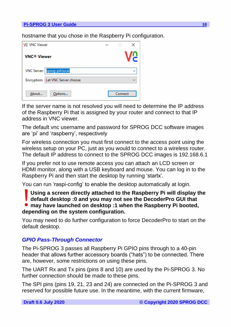
hostname that you chose in the Raspberry Pi configuration.
If the server name is not resolved you will need to determine the IP address of the Raspberry Pi that is assigned by your router and connect to that IP address in VNC viewer.
The default vnc username and password for SPROG DCC software images are ‘pi’ and ‘raspberry’, respectively
For wireless connection you must first connect to the access point using the wireless setup on your PC, just as you would to connect to a wireless router. The default IP address to connect to the SPROG DCC images is 192.168.6.1
If you prefer not to use remote access you can attach an LCD screen or HDMI monitor, along with a USB keyboard and mouse. You can log in to the Raspberry Pi and then start the desktop by running ‘startx’.
You can run ‘raspi-config’ to enable the desktop automatically at login.
Using a screen directly attached to the Raspberry Pi will display the default desktop :0 and you may not see the DecoderPro GUI that may have launched on desktop :1 when the Raspberry Pi booted,
depending on the system configuration.
You may need to do further configuration to force DecoderPro to start on the default desktop.
GPIO Pass-Through Connector
The Pi-SPROG 3 passes all Raspberry Pi GPIO pins through to a 40-pin header that allows further accessory boards (“hats”) to be connected. There are, however, some restrictions on using these pins.
The UART Rx and Tx pins (pins 8 and 10) are used by the Pi-SPROG 3. No further connection should be made to these pins.
The SPI pins (pins 19, 21, 23 and 24) are connected on the Pi-SPROG 3 and reserved for possible future use. In the meantime, with the current firmware,
!

Pi-SPROG 3 User Guide 11
Draft 0.6 July 2020 © Copyright 2020 SPROG DCC
they are connected to digital inputs and may safely be used.
The SPROG DCC Generation 5 Interface
The Pi-SPROG 3 is the first of the SPROG Generation 5 products. The interface between the host (Raspberry Pi in this case) and the Pi-SPROG 3 is based on a protocol called CBUS, develop by members of MERG. The Pi-SPROG 3 does not allow connection to a physical CBUS network and most users will not, initially at least, need to worry about the underlying operation of CBUS.
A subset of CBUS tools within in JMRI are supported by the Pi-SPROG 3 and these are described in the section JMRI Tools
Getting Started with JMRI (DecoderPro and PanelPro)
DecoderPro and PanelPro are different interface to the same underlying JMRI software. The split exists for historical reasons only. There are some differences in the functions that are available from the menus but a lot of features are available through both interfaces.
It has become customary to think of DecoderPro as the tool for programming decoders and PanelPro for controlling a layout.
DecoderPro will often be used with a dedicated programming track for ‘service mode’ programming. This allows full read and write access to all Configuration Variables (CVs) in a single decoder.
PanelPro will often be used with ‘on the main’ or ‘ops mode’ programming in conjunction with layout control. In this mode CVs may be written, but (without special hardware such as Railcom) values cannot be read back. The Pi-SPROG 3 does not support reading from decoder in ops mode. The advantage of ops mode programming is that a single loco out of all the locos on a layout me be programmed. Unlike service mode there is no single loco limit.
We will use that distinction (DecoderPro for service mode programming and PanelPro for ops mode programming) in discussing the use of the Pi-SPROG 3.
Despite this, the current Pi-SPROG 3 firmware, unlike earlier SPROG DCC products, makes little distinction between programming and operating.
Care should be taken when using the service mode programmer that only one loco is on the layout during programming, or that the layout is isolated except for a short section of track for programming. If a
programming operation is performed whilst the whole layout is
!

Pi-SPROG 3 User Guide 12
Draft 0.6 July 2020 © Copyright 2020 SPROG DCC
connected, then incorrect data may be read from CVs and all locos on the layout will be re-programmed with unpredictable results.
See the later section on the Mode Switcher tool for more information on using the Pi-SPROG 3 as a programmer or command station.
See the JMRI website https://www.jmri.org/ for any updates and latest information about JMRI.
Join the JMRI users group https://groups.io/g/jmriusers/topics for help from other JMRI users and the team who develop it.
Setting the Connection Preferences
If you have created your OS image following our instructions, or purchased it from us on SD card then you can use the desktop icons to start DecoderPro or PanelPro.
If creating your own system then please be sure to select SPROG SPROG DCC Generation 5 as the System Manufacturer and Pi-SPROG 3 as the System Connection in the connection preferences for DecoderPro or PanelPro. Our images are configured to use the ttyAMA0 serial port, rather than ttyS0.
Introduction to Service Mode Programming with DecoderPro
Start DecoderPro from the desktop icon or from a command line in a terminal window. The main window will open and show the current connection method. This merely reflects the preferences setting and does not actually indicate a physical connection.
Pi-SPROG 3 User Guide 13
Draft 0.6 July 2020 © Copyright 2020 SPROG DCC
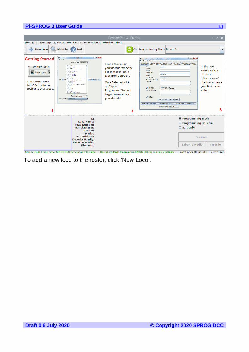
To add a new loco to the roster, click ‘New Loco’.

Pi-SPROG 3 User Guide 14
Draft 0.6 July 2020 © Copyright 2020 SPROG DCC
Clicking the control or double clicking the folder icon next to a manufacturer name will open a list of decoder types from that manufacturer. You can always manually select a decoder type in this way. In most cases, DecoderPro can determine the manufacturer and decoder type automatically.
Place a decoder equipped loco on the programming track and click on ‘Read type from decoder’.
In the example below, DecoderPro has identified a QSI Industries BLI F7.
Sometimes DecoderPro can identify the manufacturer but not exact model of decoder fitted. This is because the vendors often use the same ID version for multiple similar decoders. Often the difference is in a physical fit, e.g., a different number of function outputs available, or for the physical fit, e.g., an SD60 having a different shape from an AC44, or for a set of specific sounds for a different railroad; these do not affect the programming, and so they use a common number for that whole series of models. In these cases it will be
Pi-SPROG 3 User Guide 15
Draft 0.6 July 2020 © Copyright 2020 SPROG DCC
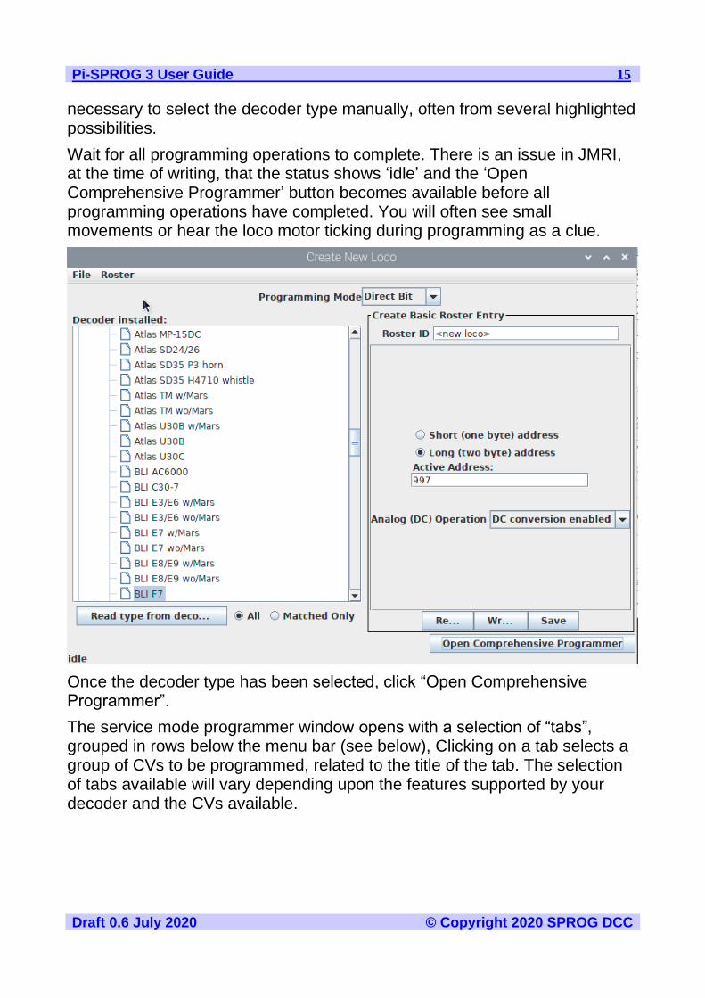
necessary to select the decoder type manually, often from several highlighted possibilities.
Wait for all programming operations to complete. There is an issue in JMRI, at the time of writing, that the status shows ‘idle’ and the ‘Open Comprehensive Programmer’ button becomes available before all programming operations have completed. You will often see small movements or hear the loco motor ticking during programming as a clue.
Once the decoder type has been selected, click “Open Comprehensive Programmer”.
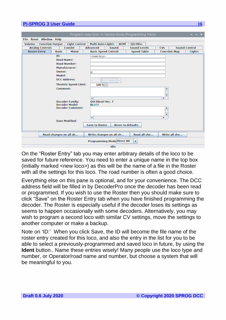
The service mode programmer window opens with a selection of “tabs”, grouped in rows below the menu bar (see below), Clicking on a tab selects a group of CVs to be programmed, related to the title of the tab. The selection of tabs available will vary depending upon the features supported by your decoder and the CVs available.
Pi-SPROG 3 User Guide 16
Draft 0.6 July 2020 © Copyright 2020 SPROG DCC
On the “Roster Entry” tab you may enter arbitrary details of the loco to be saved for future reference. You need to enter a unique name in the top box (initially marked <new loco>) as this will be the name of a file in the Roster with all the settings for this loco. The road number is often a good choice.
Everything else on this pane is optional, and for your convenience. The DCC address field will be filled in by DecoderPro once the decoder has been read or programmed. If you wish to use the Roster then you should make sure to click “Save” on the Roster Entry tab when you have finished programming the decoder. The Roster is especially useful if the decoder loses its settings as seems to happen occasionally with some decoders. Alternatively, you may wish to program a second loco with similar CV settings, move the settings to another computer or make a backup.
Note on ‘ID:’ When you click Save, the ID will become the file name of the roster entry created for this loco, and also the entry in the list for you to be able to select a previously-programmed and saved loco in future, by using the Ident button.. Name these entries wisely! Many people use the loco type and number, or Operator/road name and number, but choose a system that will be meaningful to you.

Pi-SPROG 3 User Guide 17
Draft 0.6 July 2020 © Copyright 2020 SPROG DCC
Click on the “Basic” tab and you will see the most essential settings for the decoder including the address. Initially, all of the data fields are coloured red or yellow to show that no data has been read from or written to the decoder. There are eight read and write buttons at the bottom of the window. Click “Read full sheet” to read the data for the current tab from the decoder. That will read CVs 1, 29, 17, 18, 19, 7, 8, 105 and 106 and fill in these values from the loco.
Clicking “Read all sheets” will read every CV from the decoder and may take a considerable time to complete. We recommend reading , and reviewing each sheet individually, as required.
Each data field should return to white or the background colour of the window.
Check that you see what you expected, especially if you are reading a decoder that was already programmed elsewhere!
The exact look and layout of these programming panes may vary as versions of DecoderPro or the specific decoder types are updated, but the essential information and capabilities remain consistent.
To change the locos address, type a new address in the Active Address field followed by carriage return. The address field will turn orange, indicating that the address has been changed but not yet written to the decoder. Select the
!
Pi-SPROG 3 User Guide 18
Draft 0.6 July 2020 © Copyright 2020 SPROG DCC
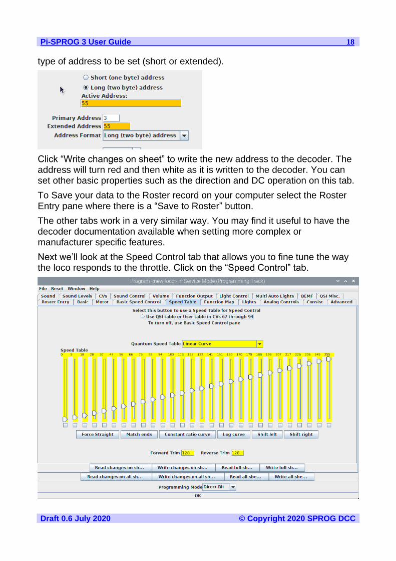
type of address to be set (short or extended).
Click “Write changes on sheet” to write the new address to the decoder. The address will turn red and then white as it is written to the decoder. You can set other basic properties such as the direction and DC operation on this tab.
To Save your data to the Roster record on your computer select the Roster Entry pane where there is a “Save to Roster” button.
The other tabs work in a very similar way. You may find it useful to have the decoder documentation available when setting more complex or manufacturer specific features.
Next we’ll look at the Speed Control tab that allows you to fine tune the way the loco responds to the throttle. Click on the “Speed Control” tab.

Pi-SPROG 3 User Guide 19
Draft 0.6 July 2020 © Copyright 2020 SPROG DCC
The decoder in this example has a choice to “Use QSI table or User table in CVs 67 through 94”. The “look and feel” of this tab will vary between decoders but most recent decoders support the use of a speed table.
It is left as an exercise for the reader to experiment with the sliders for setting the speed table and the buttons just below. The “Force Straight” option will give a linear relationship between the throttle position and the speed of the loco. “Constant ratio curve” will give little change in speed at low throttle settings, greater change at higher throttle.
Remember to write the changes on each sheet before moving to a new one.
Next, click on the “Function Map” tab.
The Function Map allows you (in those decoders that support it) to control which throttle function key is mapped to each output wire or operation (e.g. sound effect) of the decoder.
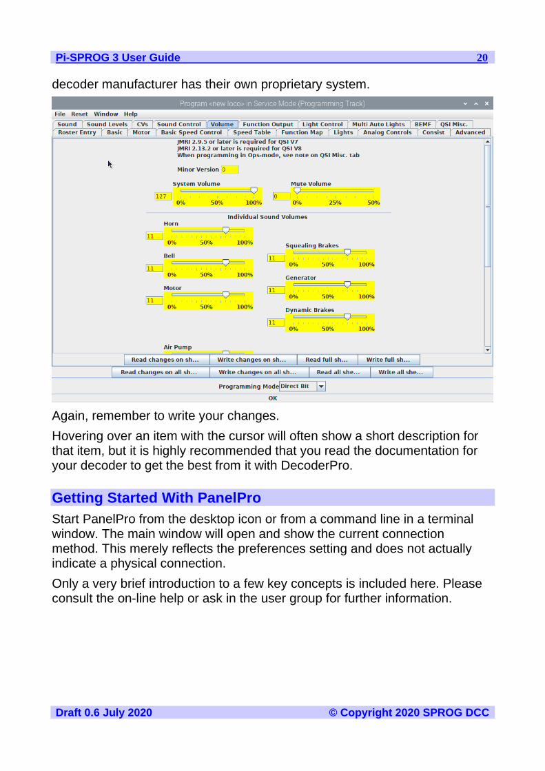
DecoderPro comes into its own for programming the many and varied options in a sound decoder. Here is an example Sound tab from the BLI F7 where the volume of individual effects may be set.
Note that it os not possible to program new sound effects or sound projects with the Pi-SPROG 3. There is no agreed standard for this, and each sound
Pi-SPROG 3 User Guide 20
Draft 0.6 July 2020 © Copyright 2020 SPROG DCC
decoder manufacturer has their own proprietary system.
Again, remember to write your changes.
Hovering over an item with the cursor will often show a short description for that item, but it is highly recommended that you read the documentation for your decoder to get the best from it with DecoderPro.
Getting Started With PanelPro
Start PanelPro from the desktop icon or from a command line in a terminal window. The main window will open and show the current connection method. This merely reflects the preferences setting and does not actually indicate a physical connection.
Only a very brief introduction to a few key concepts is included here. Please consult the on-line help or ask in the user group for further information.

Pi-SPROG 3 User Guide 21
Draft 0.6 July 2020 © Copyright 2020 SPROG DCC
Programming with PanelPro
More info TBD
Tools > Programmers > Ops Mode Programmer
Other programmers tools are also proavailable in Panelpro, but not covered in this introduction.
Turnout Tables
More info TBD.
Tools > Tables > Turnouts

Pi-SPROG 3 User Guide 22
Draft 0.6 July 2020 © Copyright 2020 SPROG DCC
Click Add.
Enter the DCC accessory address, a name and click ‘Create’.
The new turnout is added to the table.
The edit button can be used to correct mistakes. Right clicking the edit button opens a context menu with other options.

Pi-SPROG 3 User Guide 23
Draft 0.6 July 2020 © Copyright 2020 SPROG DCC
Advanced Topic: Under the hood, the CBUS protocol is used to communicate between JMRI and the Pi-SPROG 3. The turnout name ST+33 actually sends a CBUS accessory ASON event 33 to the PI-
SPROG 3. The Pi-SPROG 3 converts all CBUS accessory events directly to DCC accessory addresses, so Event 33 will operate DCC accessory 33
Power Control
Tools > Power Control
Can be used to control layout power. Changes of the layout power state will be reflected in all tools that have a power control such as the power control tool, throttles, command station monitor.
Panels
TBD
JMRI Tools
JMRI Throttles
Throttles work much as they do for any system connected to JMRI. A new throttle can be opened from the Actions > New throttle menu item in decoderPro or the Tools > Throttles > New Throttle in PanelPro.
Enter the DCC loco address and click Set. This will enable the function buttons and speed control slider.
!

Pi-SPROG 3 User Guide 24
Draft 0.6 July 2020 © Copyright 2020 SPROG DCC
Use the power control icon to control layout power (not individual locos). It must be clicked until it is green to turn on track power. If you have fitted the optional track power LED to your Pi-SPROG 3 it will flash when the track power is on.
Note: After programming using the service mode programmer, the track power is always left in the off state and must be turned on again from the throttle power control before the loco can be run.
The function keys mostly have a latching operation. Click once to turn a function on, click again to turn the function off. Right click on a function button and click ‘properties’ to change this behavior.
To control the loco speed, click and drag the slider caret (the pointy bit!). For fine control of speed, click on the slider just above or below the caret.
The “STOP!” button will stop the loco but does not turn off the track power.
To set a different loco address, click the “Dispatch” or “Release” button.
!

Pi-SPROG 3 User Guide 25
Draft 0.6 July 2020 © Copyright 2020 SPROG DCC
Connecting Throttle Devices to the Raspberry Pi Access Point
If you are using an SD card purchased from SPROG DCC, or have followed our instructions to create one, have a WiFi dongle or a Raspberry Pi with built in WiFi, then you can connect a throttle with an app such as WiThrottle or EngineDriver.
The default WiFi password is ‘pi-sprog’, unles you changed it during or after creating the SD card image.
SPROG DCC Generation 5 Tools
A number of tools are available on the SPROG DCC Generation 5 menu
These are descibed in more detail in the following sections.
Console
The console shows the traffic between the Pi-SPROG 3 and the host Raspberry Pi. It is useful for capturing diagnostic information if a problem occurs that is repeatable. It is not required for normal, everyday, operation.
The Node Manager
The node Manager allows access to internal settings in the Pi-SPROG 3. It is not required for normal, everyday, operation, unless you need to change a mode that used to be set in the SPROG mode word in earlier versions.
The node manager is started from the SPROG DCC Generation 5 > Node Manager menu item.
Pi-SPROG 3 User Guide 26
Draft 0.6 July 2020 © Copyright 2020 SPROG DCC
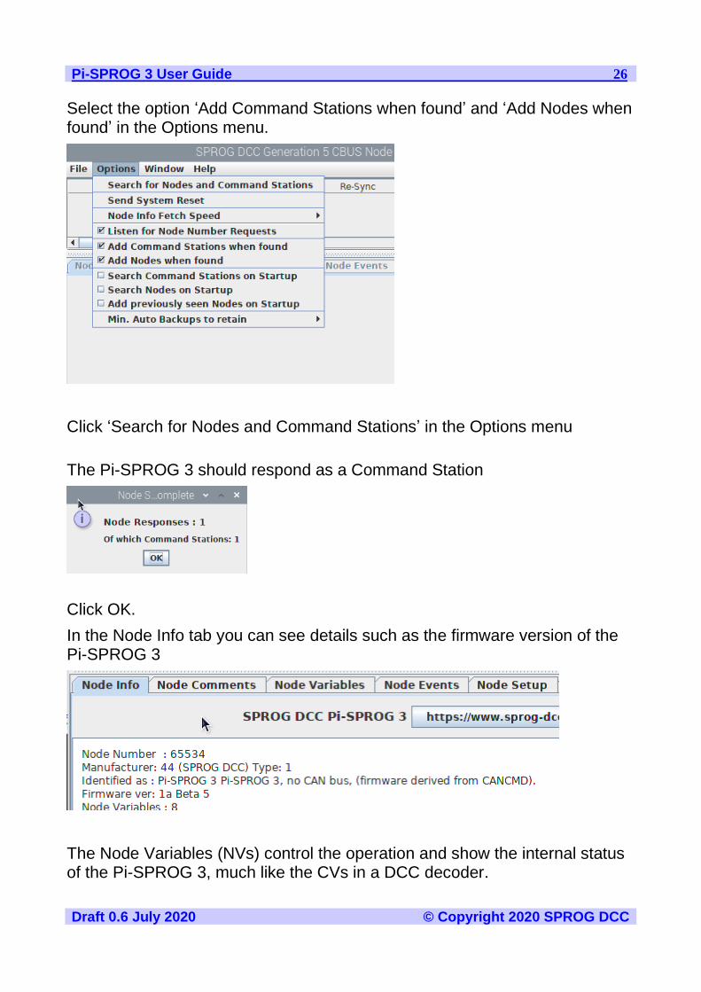
Select the option ‘Add Command Stations when found’ and ‘Add Nodes when found’ in the Options menu.
Click ‘Search for Nodes and Command Stations’ in the Options menu
The Pi-SPROG 3 should respond as a Command Station
Click OK.
In the Node Info tab you can see details such as the firmware version of the Pi-SPROG 3
The Node Variables (NVs) control the operation and show the internal status of the Pi-SPROG 3, much like the CVs in a DCC decoder.

Pi-SPROG 3 User Guide 27
Draft 0.6 July 2020 © Copyright 2020 SPROG DCC
Node
Variable
Values Default Function
1 0,1 0 Setup mode – do not use
2 0,1 0 Set to 1 for compatibility with ZTC decoders
3 0,1 0 Set to 1 for Broadway Limited decoders
4 0,1 0 Set to 1 for Zimo large scale decoders
5 0,1 0 Programmer/Command station mode – use the Mode Switcher tool
6 0 – 255 249 Track current limit in mA/10. E.g. default is 2490 mA or 2.49 A. This must always be lower than the power supply current limit.
7 0 – 255 - Read only input voltage in Vx10, e.g. 118 represents 11.8 V
8 0 – 255 - Read only track current in mA/10
9 1 – 7 1 Accessory packet repeat count.
10 0,1 0 Multimeter mode. Set to 1 to enable voltage and current reporting.
11 14 – 255 14 Number of pre-amble bits sent between packets
Voltage and current measurements are for information only and accurate to
Pi-SPROG 3 User Guide 28
Draft 0.6 July 2020 © Copyright 2020 SPROG DCC
+/-5%.
To change an NV use the spinner to select the new value, or type the new value directly, click the save button and then confirm the operation in the pop up dialog.
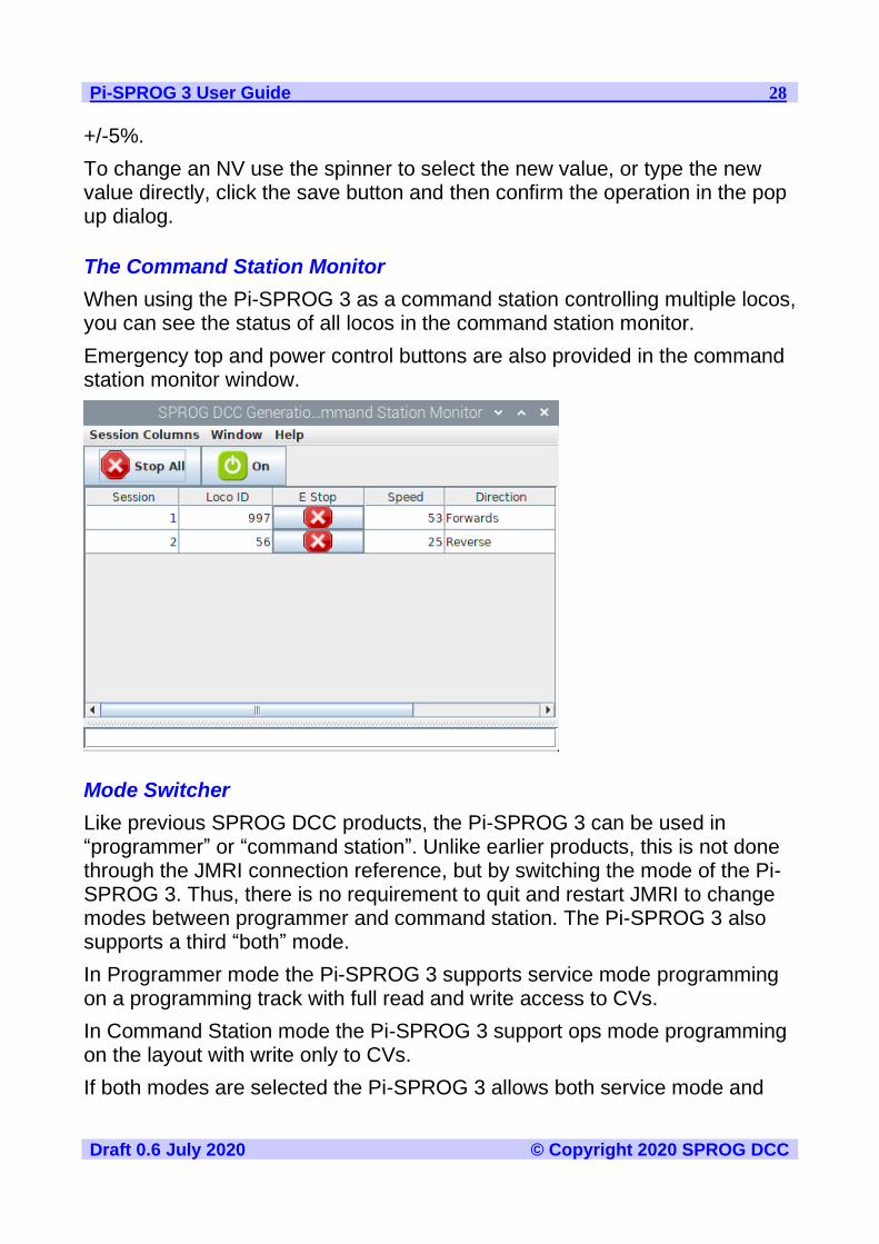
The Command Station Monitor
When using the Pi-SPROG 3 as a command station controlling multiple locos, you can see the status of all locos in the command station monitor.
Emergency top and power control buttons are also provided in the command station monitor window.
Mode Switcher
Like previous SPROG DCC products, the Pi-SPROG 3 can be used in “programmer” or “command station”. Unlike earlier products, this is not done through the JMRI connection reference, but by switching the mode of the Pi-SPROG 3. Thus, there is no requirement to quit and restart JMRI to change modes between programmer and command station. The Pi-SPROG 3 also supports a third “both” mode.
In Programmer mode the Pi-SPROG 3 supports service mode programming on a programming track with full read and write access to CVs.
In Command Station mode the Pi-SPROG 3 support ops mode programming on the layout with write only to CVs.
If both modes are selected the Pi-SPROG 3 allows both service mode and

Pi-SPROG 3 User Guide 29
Draft 0.6 July 2020 © Copyright 2020 SPROG DCC
ops mode programming. This mode shoul be used with care when the Pi-SPROG 3 is connected to a layout as all decoders will be reprogrammed is service mode is used.
The mode is changed using the mode switcher tool. Two radio buttons allow selection of Programmer, Command Station or both modes.
The status bar of the DecoderPro window will be updated to show which programmer modes are available or “on-line”.
The mode is set in the Pi-SPROG 3 and also saved as a JMRI preference so that it will be re-instated if the software is restarted. If the Pi-SPROG 3 is used on a different system, reprogrammed with the bootloader or the JMRI preferences are lost then it is possible that the modes can become out of step. In that case simply use the tool to set the desired mode.
Track Current and Track Voltage
If Node Variable 10, Multimeter Mode, is set to 1 in the Pi-SPROG 3 then it will send regular voltage and current measurements. These may be displayed

Pi-SPROG 3 User Guide 30
Draft 0.6 July 2020 © Copyright 2020 SPROG DCC
in the Track Voltage and Track Current tools.
Pi-SPROG 3 Firmware Updates
Pi-SPROG 3 firmware updates are performed using the Firmware Update tool in JMRI.
Firmware upgrade files (.hex files) will be available from SPROG DCC when an update is available.
Start the Firmware Update Tool from the SPROG DCC Generation 5 menu in JMRI.
Pi-SPROG 3 User Guide 31
Draft 0.6 July 2020 © Copyright 2020 SPROG DCC
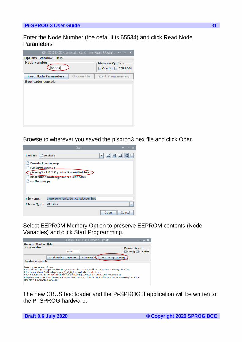
Enter the Node Number (the default is 65534) and click Read Node Parameters
Browse to wherever you saved the pisprog3 hex file and click Open
Select EEPROM Memory Option to preserve EEPROM contents (Node Variables) and click Start Programming.
The new CBUS bootloader and the Pi-SPROG 3 application will be written to the Pi-SPROG hardware.
Pi-SPROG 3 User Guide 32
Draft 0.6 July 2020 © Copyright 2020 SPROG DCC
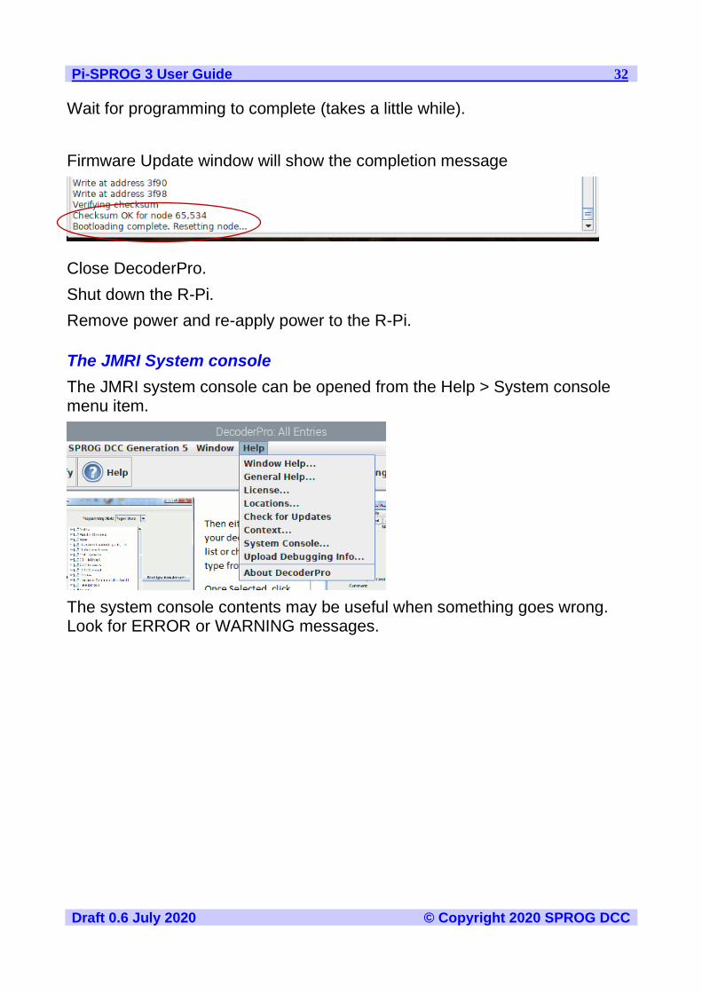
Wait for programming to complete (takes a little while).
Firmware Update window will show the completion message
Close DecoderPro.
Shut down the R-Pi.
Remove power and re-apply power to the R-Pi.
The JMRI System console
The JMRI system console can be opened from the Help > System console menu item.
The system console contents may be useful when something goes wrong. Look for ERROR or WARNING messages.
Pi-SPROG 3 User Guide 33
Draft 0.6 July 2020 © Copyright 2020 SPROG DCC
Known Issues at time of writing
Pi-SPROG 3 does not reset correctly unless power cycled after bootloading.
Troubleshooting
Before reporting any problems please check the SPROG DCC website for any bug reports or updates.
If you are experiencing intermittent faults with your Pi-SPROG 3, please ensure that you are using a good quality DC, regulated power supply.
Useful Links
SPROG homepage https://www.sprog-dcc.co.uk for the latest information, updates, downloads, etc., for Pi-SPROG 3.
North American distributor for Pi-SPROG 3 http://www.bbmgroup.com/sprog
SPROG DCC discussion group https://groups.io/g/sprog-dcc for latest news and discussion.
Java Model railroad Interface https://www.jmri.org/ for DecoderPro.
JMRI users group https://groups.io/g/jmriusers/topics for latest news and discussion.
Model Electronics Railway Group https://www.merg.org.uk/
Raspberry Pi Forums https://www.raspberrypi.org/forums/ You will find far more knowledge here, than we are able to offer!