
Physics of Magnetic Resonance Chapter 12 Biomedical Engineering Dr. Mohamed Bingabr University of...
47
Physics of Magnetic Resonance Chapter 12 Biomedical Engineering Dr. Mohamed Bingabr University of Central Oklahoma
-
Upload
amberlynn-parrish -
Category
Documents
-
view
227 -
download
2
Transcript of Physics of Magnetic Resonance Chapter 12 Biomedical Engineering Dr. Mohamed Bingabr University of...

Physics of Magnetic ResonanceChapter 12
Biomedical EngineeringDr. Mohamed Bingabr
University of Central Oklahoma

Outline
• Introduction• Microscopic Magnetization• Macroscopic Magnetization• Precession and Larmor Frequency• Transverse and Longitudinal Magnetization• RF Excitation• Relaxation• The Bloch Equation• Spin Echoes• Basic Contrast Mechanisms

Magnetic Resonance ImagingA projection of the three-dimensional volume of the body onto a two-dimensional imaging surface.MRI is the imaging of hydrogen density in tissues.
Advantage:1- High image quality2- risk-free imaging
Disadvantage: high cost
Uses: Assess Neurological effects of stroke, trauma or disease. Orthopedic scans for injuries and degeneration involving knees, shoulders, feet and ankles.

Magnetic Resonance Imaging
Magnetic Field Strength
Earth: 25 to 65 microTesla
External Magnetic field B0 = 0.5 to 7 Tesla
Gradient Magnetic Coil = 10-60 mTesla/meter
1 Tesla = 10,000 Gauss
x
y
z

Microscopic Magnetization

1.5 T vs. 3.0 T (3D MR Angiography)
1.5 T 3.0 T

Microscopic Magnetization
Nucleus with either an odd atomic number or an odd mass number has an angular momentum , and spin.
Microscopic magnetic field has a magnetic moment vector μ.
𝛍=𝛾𝚽
: gyromagnetic ratio with unit radian per second per tesla
𝛾=𝛾 /2𝜋 Hz/tesla

Microscopic Magnetization
No net magnetization in the absence of external magnetic source.

Nuclear Magnetization
PositiveOrientation
(Lower Energy)
NegativeOrientation
(Higher energy)
x
y
z
x
y
z
MagneticField (B0)
54o
126o

Macroscopic MagnetizationNet Magnetization
x
y
z
x
y
z B0 M
𝐌𝒛(𝐫 ,𝑡 )=∑𝑛=1
𝑁𝑠
𝜇𝑛
𝐌𝒙𝒚 (𝐫 , 𝑡)=0

Macroscopic Magnetization
After a while M will reach its equilibrium value M0
𝑀 0=𝐵0𝛾
2 h2
4 𝑘𝑇𝑃𝐷
PD= proton densityT: temperature from absolute value
Why can't we measure the Magnetic field M?

Macroscopic Magnetization
Equation that describes the motion of a gyroscope is
where L(t) is the gyroscope’s angular momentum, r the radius from the fixed point of rotation, m the mass, and g earth gravity.
𝑑𝐋 (𝑡)𝑑𝑡
=𝒓 ×𝑚𝐠

Precession and Larmor FrequencyM(t) is a magnetic moment and it experiences a torque at the presence of a time-varying magnetic field B(t).
𝑑𝐌(𝑡)𝑑𝑡
=𝛾𝐌(𝑡)×𝐁(𝑡)
If B(t) is a static magnetic field equal B0 at the z direction and the initial magnetization M(0) equal M0 and oriented at an angle relative to the z axis then the solution is:𝑀 𝑧 (𝑡 )=𝑀0 c 𝑜𝑠𝛼
𝑀 𝑥 (𝑡 )=𝑀0 sin𝛼 cos (−𝛾 𝐵0𝑡+𝜙 )
𝑀 𝑦 (𝑡 )=𝑀 0 sin𝛼 sin ( −𝛾 𝐵0 𝑡+𝜙 )

Precession and Larmor Frequency
These equations describe a precession of M(t) around B0 with a frequency called Larmor frequency.
𝜔0=𝛾 𝐵0 𝑣0=𝛾 𝐵0
𝑀 𝑥 (𝑡 )=𝑀0 sin𝛼 cos (− 2𝜋 𝑣0𝑡+𝜙 )
𝑀 𝑦 (𝑡 )=𝑀 0 sin𝛼 sin ( −2𝜋𝑣0 𝑡+𝜙 )𝑀 𝑧 (𝑡 )=𝑀0 c 𝑜𝑠𝛼
𝑀 𝑧 (𝑡 )=𝑀0 c 𝑜𝑠𝛼
𝑀 𝑥 (𝑡 )=𝑀0 sin𝛼 cos (−𝛾 𝐵0𝑡+𝜙 )
𝑀 𝑦 (𝑡 )=𝑀 0 sin𝛼 sin ( −𝛾 𝐵0 𝑡+𝜙 )
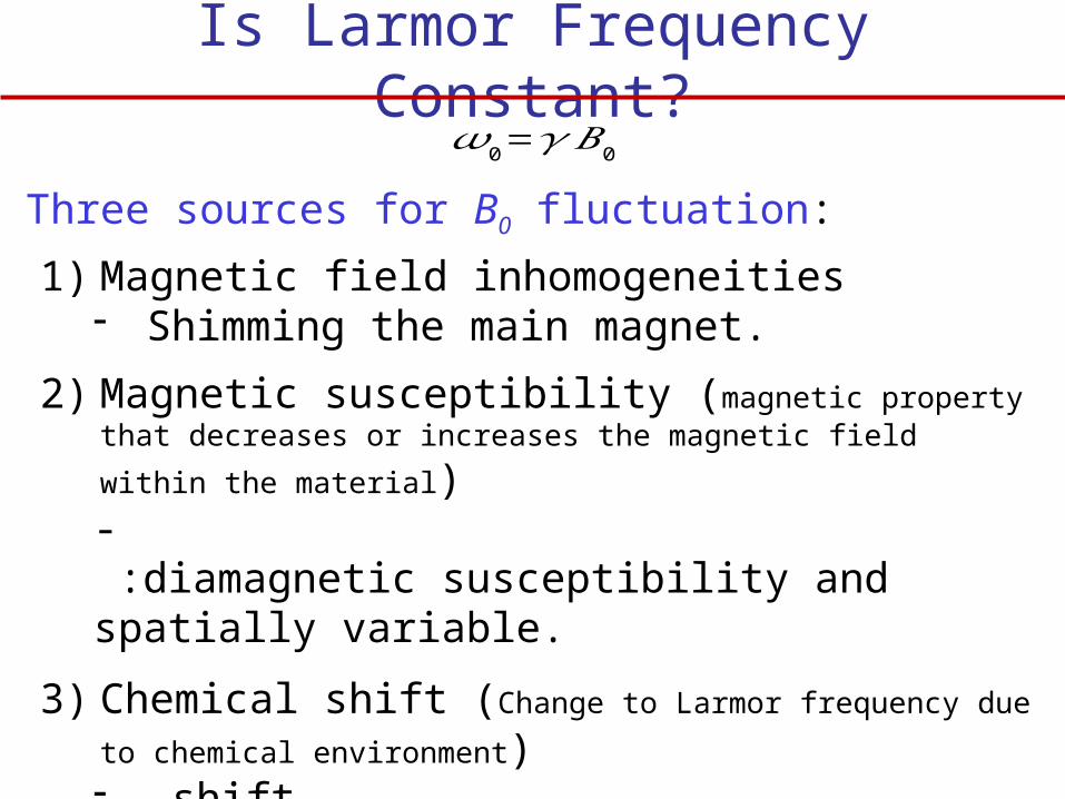
Is Larmor Frequency Constant?
Three sources for B0 fluctuation:
𝜔0=𝛾 𝐵0
1) Magnetic field inhomogeneities- Shimming the main magnet.
2) Magnetic susceptibility (magnetic property that decreases or
increases the magnetic field within the material)- :diamagnetic susceptibility and spatially variable.
3) Chemical shift (Change to Larmor frequency due to chemical
environment)- shift- :Shielding constant
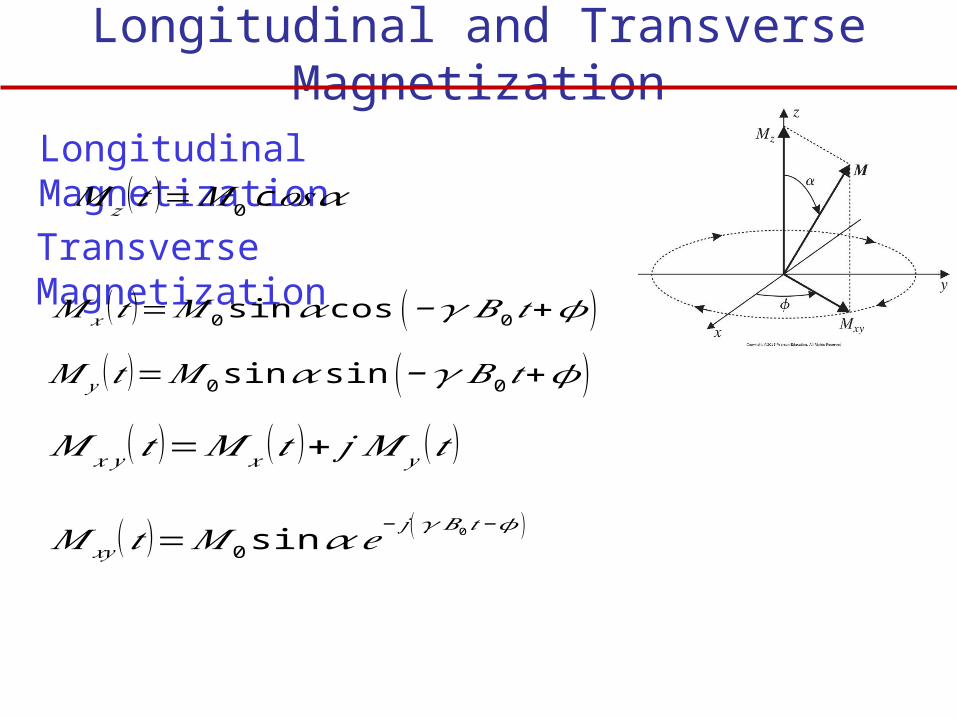
Longitudinal and Transverse Magnetization
𝑀 𝑥𝑦 (𝑡 )=𝑀 0 sin𝛼𝑒− 𝑗 (𝛾 𝐵0 𝑡 −𝜙)
Transverse Magnetization
Longitudinal Magnetization𝑀 𝑧 (𝑡 )=𝑀0 c 𝑜𝑠𝛼
𝑀 𝑥 (𝑡 )=𝑀0 sin𝛼 cos (−𝛾 𝐵0𝑡+𝜙 )
𝑀 𝑦 (𝑡 )=𝑀 0 sin𝛼 sin ( −𝛾 𝐵0 𝑡+𝜙 )
𝑀 𝑥 𝑦 (𝑡 )=𝑀 𝑥 (𝑡 )+ 𝑗 𝑀 𝑦 (𝑡 )

𝜃
NMR SignalsA coil placed next to the area need to image will experience magnetic field radiated from the subject. This magnetic field will induce electric voltage in the coil proportional to the transverse magnetic field (Faraday’s Law).
𝑉 (𝑡 )=−𝜕𝜕𝑡 ∫
o bject
❑
M (r , 𝑡 ) .𝐁𝑟 (𝐫 ) 𝑑𝐫
𝑉 (𝑡 )=−𝜕𝜕𝑡 ∫
o bject
❑
𝑀𝑥 (𝑡 )𝐵𝑥𝑟+𝑀 𝑦 (𝑡 )𝐵𝑦
𝑟 𝑑 r
𝑉 (𝑡 )=−𝑉 𝑠𝜕𝜕𝑡 [𝑀 𝑥 (𝑡 )𝐵𝑥
𝑟+𝑀 𝑦 (𝑡 )𝐵𝑦𝑟 ]
Vs is the volume of the sample
Br is the magnetic field produced by the transmitter (coil) to control the magnetization vector M.

𝜃
NMR Signals
𝑉 (𝑡 )=−𝑉 𝑠𝜕𝜕𝑡 [𝑀 𝑥 (𝑡 )𝐵𝑥
𝑟+𝑀 𝑦 (𝑡 )𝐵𝑦𝑟 ]
𝑉 (𝑡 )=− 2𝜋 𝑣0𝑉 𝑠𝑀0 𝑠𝑖𝑛𝛼 [𝐵𝑥𝑟 𝑠𝑖𝑛 (− 2𝜋 𝑣0𝑡+𝜙 ) −𝐵𝑦
𝑟 𝑠𝑖𝑛 (− 2𝜋 𝑣0𝑡+𝜙 ) ]𝑉 (𝑡 )=− 2𝜋 𝑣0𝑉 𝑠𝑀0 𝑠𝑖𝑛𝛼𝐵
𝑟 𝑠𝑖𝑛 (− 2𝜋 𝑣0𝑡+𝜙−𝜃𝑟 )
𝐵𝑥𝑟=𝐵𝑟𝑐𝑜𝑠 𝜃𝑟 𝐵𝑦
𝑟 =𝐵𝑟 𝑠𝑖𝑛𝜃 𝑟
𝑀 𝑥 (𝑡 )=𝑀0 sin𝛼 cos (− 2𝜋 𝑣0𝑡+𝜙 )Remember
𝑀 𝑦 (𝑡 )=𝑀 0 sin𝛼 sin ( −2𝜋𝑣0 𝑡+𝜙 )
The frequency v0 of V(t) will determine the location of the voxel in the body from which the NMR is radiating, and the magnitude will determine the density of the H atoms in the voxel.
The x-y components of the magnetic field Br are

Maximizing the Magnitude of NMR Signals
The goal is to maximize the magnitude of the NMR signal:
|𝑉 (𝑡 )|=2𝜋𝑣0𝑉 𝑠𝑀 0𝐵𝑟 sin𝛼
is called the tip angle or flip angle. Increasing will increase the time to obtain the NMR signal.Increasing Vs will reduce the resolution.
Example:If we want to double the resolution in all three dimensions, by how much should we increase the value of B0 if it was initially 1.5 tesla?

RF Excitation
1) RF excitation is established by a pulse of alternating current running through an antenna (coil) surrounding the sample.
2) The antenna will radiate circularly polarized magnetic field B1(t) with Larmor frequency.
3) When the frequencies of B1(t) and M(t) are the same then M(t) will be pushed away from the external magnetic field B0 by tip angle α.
4) The value of α depends proportionally on the strength of the pulse and the time duration.
When the magnetization vector M is aligned with the strong external vector B0 it is very hard to detect M by the RF antenna. RF excitation is the tool to push M vector away from the B0 in order to detect M.

RF Excitation
The circularly RF excitation pulse B1(t)
𝐵1 (𝑡 )=𝐵1𝑒(𝑡)𝑒− 𝑗 ( 2𝜋𝑣0 𝑡 −𝜑 )
Rotational plane
Common RF pulses are the (pi over 2) and the (the inversion pulse). The final tip angle after an RF excitation of duration is
𝛼=𝛾∫0
𝜏𝑝
𝐵1𝑒 (𝑡 )𝑑𝑡
For rectangular pulse

RF Excitation
Example We apply an RF pulse to a sample of protons. The sample is in equilibrium with the B0 field in the +Z direction. We need to tip the magnetization vector M into the x-y plane in 3 ms. What should the strength of RF excitation be?
𝛼=𝛾 𝐵1𝜏𝑝

Relaxation after the Excitation α PulseAt the end of the α pulse, M will precess in response to the presence of the main magnetic field B0. The received signal Mxy(t) will slowly decay due to transverse and longitudinal relaxations mechanisms.
Mxy
Mz
Mxy
Mz
Mxy
Mz
MMM
Mxy
Mz M0
Time Pass Time Pass Time Pass
transverse relaxations
transverse relaxations

Transverse (Spin-Spin) Relaxation
Transverse Relaxation (spin-spin relaxation) Perturbations in the magnetic field causes some protons to momentarily speed up or slow down, changing their phase. As a result Mxy exponentially decay to zero.

Transverse RelaxationThe decayed received signal in the antenna is called free induction decay (FID). The decay time constant is called transverse relaxation time T2.
𝑀 𝑥𝑦 (𝑡 )=𝑀 0 sin𝛼𝑒− 𝑗 (𝛾 𝐵0𝑡 −𝜙)𝑒−𝑡 /𝑇2
T2 depends on the types of tissues (causes contrast).Local perturbations in the static field B0 makes the actual decay time for FID, , shorter so < T2.

T2 of Some Normal Tissue Types
Tissue T2 (ms)gray matter 100
white matter 92muscle 47
fat 85
kidney 58liver 43
Even though the actual decay time for FID is , the T2 decay still can be measured by special RF pulsing sequence called spin echoes. Spin echoes pulse exploit the latent magnetization coherence that last T2.
1
𝑇2∗=
1T 2
+1
𝑇 2′

Longitudinal (spin-lattice) RelaxationThe longitudinal relaxation time (T1) is the time it takes for the longitudinal magnetization Mz(t) to recovers back to its equilibrium value M0. Mz(t) rises exponentially the rising time T1 depends on the tissue property.
𝑀 𝑧 (𝑡 )=𝑀0 (1 −𝑒−𝑡 /𝑇 1 )+𝑀 𝑧 ¿
𝑀 𝑧 ¿: longitudinal magnetization immediately after the pulse.
M
M
Mz M0
Mxy
Mz(0+) Mα
Time
Time

T1 and T2 for Different Tissues
250 ms < T1< 2500 ms25 ms < T2 < 250 ms
5 T2 < T1 < 10 T2

ExamplesA sample is in equilibrium if there have been no external excitation for at least 3 times the largest T1 in the sample.
Example:Suppose a sample is in equilibrium, and a /2 pulse is applied. What happens to the longitudinal magnetization of the sample?
Example:Suppose a sample is in equilibrium, and an pulse is applied. What are the transverse and longitudinal magnetizations of the sample, expressed in the rotating and non rotating frames?

The Block EquationsBlock equations describe the behavior of the magnetic spin at the presence of the forced magnetic fields and the relaxation behavior.
𝑑𝐌(𝑡)𝑑𝑡
=𝛾𝐌 (𝑡 )×𝐁 (𝑡 )− R {𝐌 (𝑡 )−𝐌0 }
𝐁 (𝑡 )=𝐁0+𝐁1(𝑡) R=(1/𝑇 2 0 00 1/𝑇2 00 0 1/𝑇1
)

The Block Equations
After pulse, the RF field B1 is shut down and only B0 is nonzero. Therefore B1x(t) = B1y(t) = 0 and B(t) = B0
𝑀 𝑥 (𝑡 )=𝑀0 sin𝛼 cos (− 2𝜋 𝑣0𝑡+𝜙 )𝑒−𝑡 /𝑇 2
𝑀 𝑦 (𝑡 )=𝑀 0 sin𝛼 sin ( −2𝜋𝑣0 𝑡+𝜙 )𝑒− 𝑡 /𝑇 2
𝑀 𝑧 (𝑡 )=𝑀0 cos𝛼 (1 −𝑒−𝑡 /𝑇1 )+𝑀 𝑧¿

Magnetization M for /2 Pulse
𝑀 𝑥 (𝑡 )=−𝑀 0 sin (2𝜋𝑣0 𝑡 )𝑒−𝑡 /𝑇 2
𝑀 𝑦 (𝑡 )=−𝑀 0cos (2𝜋𝑣0 𝑡 )𝑒−𝑡 /𝑇 2
𝑀 𝑧 (𝑡 )=𝑀 𝑧¿
For =/2 and =0, then

Spin Echoes to Measure T2
Pure transverse relaxation, characterized by the time constant T2, is a random phenomenon. Randomness is a characteristic of the tissue. A /2 RF pulse followed by pulse elicit the spin echoes transverse signal Mxy(t).
Two mechanisms that causes spin echo amplitude to decrease:1- Longitudinal relaxation T1
2- Phase of the coherent echo is never perfectly aligned.
The problem is FID decay at the rate of , which is much smaller than T2

Spin Echoes to Measure T2
TE is the echo time
𝑇 2∗
T2

Spin Echoes to Measure T2

ExampleSuppose two 1H isochromats are in different locations in a 1.5 T magnet, and the fractional difference in field strength is 20 ppm (parts per million). a) How long will it take before these isochromats are
180o out of phase?b) What will be their phase difference at TE/2 if the
echo time is 4 ms?

T1-Weighted Contrast ImageThe image intensity is proportional to the time relaxation of the longitudinal component of magnetization.

Spin-Spin Pulse to measure T1
B0
Tr
𝑀 𝑧 (𝑡 )=𝑀0 (1 −𝑒−𝑡 /𝑇 1 )+𝑀 0 cos𝛼𝑒−𝑡 /𝑇 1
T1

Spin-Spin Pulse to measure T1
• When the sample at equilibrium and excited by pulse then
• After T1 which is larger than 3 times T2, Mxy will be negligible but Mz(t) will have value
• If at time TR=T1 the tissue is excited with another pulse then the transverse magnetization
𝑀 𝑥𝑦 (𝑡 )=𝑀 0 sin𝛼𝑒− 𝑗 ( 2𝜋𝑣0𝑡−𝜙 )𝑒− 𝑡 /𝑇 2
𝑀 𝑧 (𝑡 )=𝑀0 (1 −𝑒−𝑡 /𝑇 1 )+𝑀 𝑧 ¿
𝑀 𝑥𝑦 (𝑡 )=𝑀 𝑧 (0−) sin𝛼 𝑒− 𝑗 ( 2𝜋𝑣0 𝑡 −𝜙)𝑒−𝑡 /𝑇2

Basic Contrast MechanismsThe transverse magnetization Mxy(t) produces the measurable MR signal.
Tissue contrast in MRI determined by
1. Tissue properties PD, T2, and T1.
2. Characteristic of the externally applied excitations:
a. Tip angle
b. Echo time TE
c. Pulse repetition interval TR
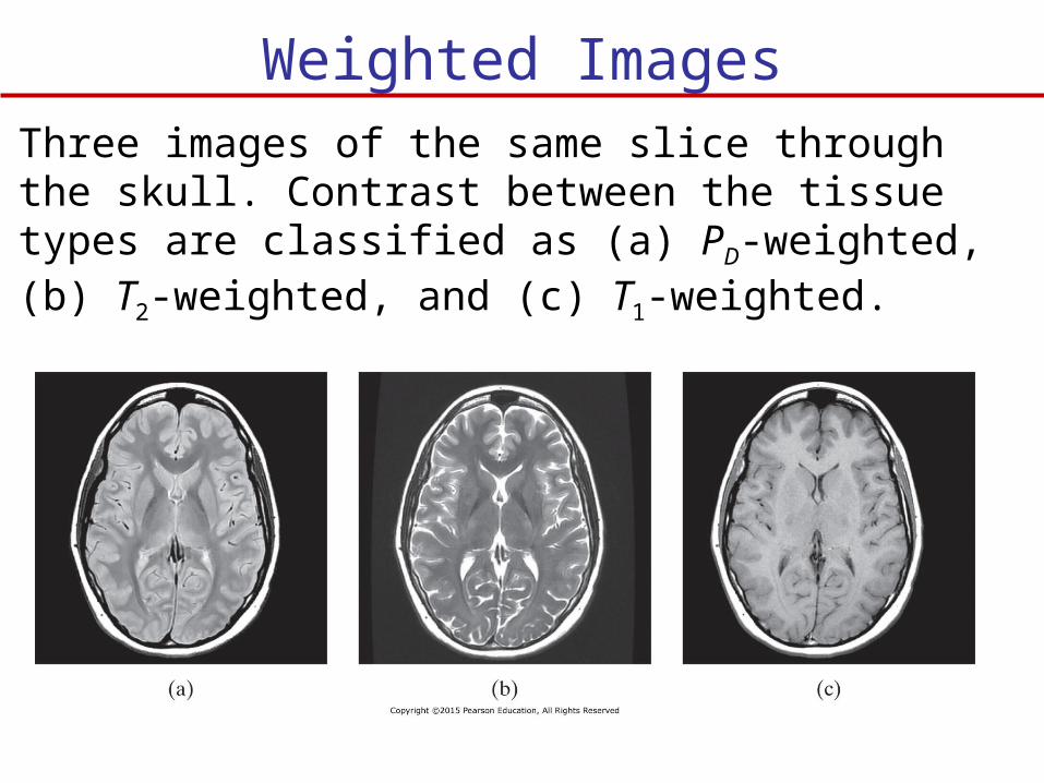
Weighted ImagesThree images of the same slice through the skull. Contrast between the tissue types are classified as (a) PD-weighted, (b) Τ2-weighted, and (c) Τ1-weighted.

Brain Tissue Parameters
Water 3000 3000Liver 45 420Fat 85 240

PD-Weighted Contrast Image
• The image intensity is proportional to the number of hydrogen nuclei in the sample.
• Need to image the sample in equilibrium before the signal has a chance to decay from T2 effects.
• RF signal: Long TR = 3500 ms, short TE=17 ms, and =/2.

T2-Weighted Contrast Image
• The image intensity is proportional to the transverse relaxation times of different tissues.
• RF signal: Long TR = 3500 ms, long TE = T2 of the tissues being imaged.
• GM and WM has small contrast with respect to each other and large contrast with respect to CSF.
• WM is slightly darker than GM because its NMR signal has decayed slightly faster.

T1-Weighted Contrast Image
• RF signal: Short TR = 600 ms, short TE = 17 ms and = /2.
• TR falls in between the T1 values for GM and WM but is much smaller than that of CSF.
• GM and WM will have recovered approximately two-thirds of their longitudinal magnetization, whereas CSF will have recovered relatively little.
• CSF signal smaller than GM and WM signals.
• GM and WM are relatively bright, while the CSF is dark in the image.

Inversion RecoveryInversion recovery uses a 180o RF pulse to establish T1 contrast.
𝑀 ¿
𝑀 𝑧 (𝑡 )=𝑀0 (1 −2𝑒−𝑡 /𝑇 1 )
Let tnull be the time when Mz = 0
tnull = T1 ln 2
After 180o RF pulse
After /2 pulse at tnull Mz = 0 and
𝑀 𝑥𝑦 ¿
Tissues of different T1 will have Mxy values and will be imaged. Inversion recovery is used to suppress certain tissues

Animation and More DetailMRI is taught as a one semester course. For more detail and animation visit the following website:
http://www.cis.rit.edu/htbooks/mri/inside.htm
Magnetic Resonance Laboratory at Rochester Institute of Technology.