Physics for Scientists and Engineers, 8th Ed · The image formed by the mirror in Figure 36.1 is...
44
1040 chapter 36 Image Formation 36.1 Images Formed by Flat Mirrors 36.2 Images Formed by Spherical Mirrors 36.3 Images Formed by Refraction 36.4 Images Formed by Thin Lenses 36.5 Lens Aberrations 36.6 The Camera 36.7 The Eye 36.8 The Simple Magnifier 36.9 The Compound Microscope 36.10 The Telescope This chapter is concerned with the images that result when light rays encounter flat or curved surfaces between two media. Images can be formed by either reflection or refraction due to these surfaces. We can design mirrors and lenses to form images with desired characteristics. In this chapter, we continue to use the ray approximation and assume light travels in straight lines. We first study the formation of images by mirrors and lenses and techniques for locating an image and determining its size. Then we investigate how to combine these elements into several useful optical instru- ments such as microscopes and telescopes. The light rays coming from the leaves in the background of this scene did not form a focused image in the camera that took this photograph. Consequently, the back- ground appears very blurry. Light rays passing though the raindrop, however, have been altered so as to form a focused image of the background leaves for the camera. In this chapter, we investigate the formation of images as light rays reflect from mirrors and refract through lenses. (Don Hammond Photography Ltd. RF) t
Transcript of Physics for Scientists and Engineers, 8th Ed · The image formed by the mirror in Figure 36.1 is...

1040
chapter 36Image Formation36.1 Images Formed by Flat Mirrors
36.2 Images Formed by Spherical Mirrors
36.3 Images Formed by Refraction
36.4 Images Formed by Thin Lenses
36.5 Lens Aberrations
36.6 The Camera
36.7 The Eye
36.8 The Simple Magnifier
36.9 The Compound Microscope
36.10 The Telescope
This chapter is concerned with the images
that result when light rays encounter flat
or curved surfaces between two media.
Images can be formed by either reflection
or refraction due to these surfaces. We can
design mirrors and lenses to form images
with desired characteristics. In this chapter,
we continue to use the ray approximation
and assume light travels in straight lines.
We first study the formation of images
by mirrors and lenses and techniques for
locating an image and determining its size.
Then we investigate how to combine these
elements into several useful optical instru-
ments such as microscopes and telescopes.
The light rays coming from the leaves in the background of this scene did not form a focused image in the camera that took this photograph. Consequently, the back-ground appears very blurry. Light rays passing though the raindrop, however, have been altered so as to form a focused image of the background leaves for the camera. In this chapter, we investigate the formation of images as light rays reflect from mirrors and refract through lenses. (Don Hammond Photography Ltd. RF)
t
36.1 | Images Formed by Flat Mirrors 1041
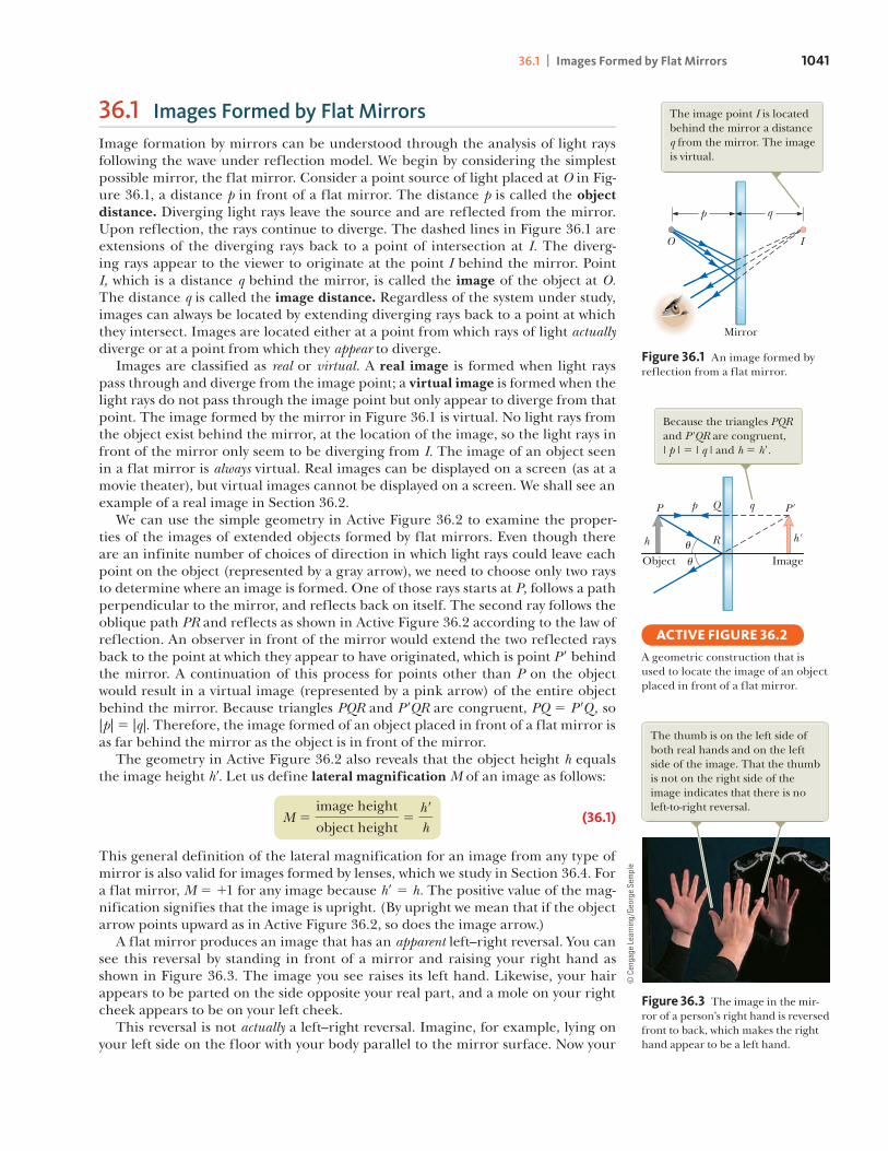
36.1 Images Formed by Flat MirrorsImage formation by mirrors can be understood through the analysis of light rays following the wave under reflection model. We begin by considering the simplest possible mirror, the flat mirror. Consider a point source of light placed at O in Fig-ure 36.1, a distance p in front of a flat mirror. The distance p is called the object distance. Diverging light rays leave the source and are reflected from the mirror. Upon reflection, the rays continue to diverge. The dashed lines in Figure 36.1 are extensions of the diverging rays back to a point of intersection at I. The diverg-ing rays appear to the viewer to originate at the point I behind the mirror. Point I, which is a distance q behind the mirror, is called the image of the object at O.The distance q is called the image distance. Regardless of the system under study, images can always be located by extending diverging rays back to a point at which they intersect. Images are located either at a point from which rays of light actuallydiverge or at a point from which they appear to diverge. Images are classified as real or virtual. A real image is formed when light rays pass through and diverge from the image point; a virtual image is formed when the light rays do not pass through the image point but only appear to diverge from that point. The image formed by the mirror in Figure 36.1 is virtual. No light rays from the object exist behind the mirror, at the location of the image, so the light rays in front of the mirror only seem to be diverging from I. The image of an object seen in a flat mirror is always virtual. Real images can be displayed on a screen (as at a movie theater), but virtual images cannot be displayed on a screen. We shall see an example of a real image in Section 36.2. We can use the simple geometry in Active Figure 36.2 to examine the proper-ties of the images of extended objects formed by flat mirrors. Even though there are an infinite number of choices of direction in which light rays could leave each point on the object (represented by a gray arrow), we need to choose only two rays to determine where an image is formed. One of those rays starts at P, follows a path perpendicular to the mirror, and reflects back on itself. The second ray follows the oblique path PR and reflects as shown in Active Figure 36.2 according to the law of reflection. An observer in front of the mirror would extend the two reflected rays back to the point at which they appear to have originated, which is point P9 behind the mirror. A continuation of this process for points other than P on the object would result in a virtual image (represented by a pink arrow) of the entire object behind the mirror. Because triangles PQR and P9QR are congruent, PQ 5 P9Q, so |p| 5 |q|. Therefore, the image formed of an object placed in front of a flat mirror is as far behind the mirror as the object is in front of the mirror. The geometry in Active Figure 36.2 also reveals that the object height h equals the image height h9. Let us define lateral magnification M of an image as follows:
M 5image height
object height5
h rh
(36.1)
This general definition of the lateral magnification for an image from any type of mirror is also valid for images formed by lenses, which we study in Section 36.4. For a flat mirror, M 5 11 for any image because h9 5 h. The positive value of the mag-nification signifies that the image is upright. (By upright we mean that if the object arrow points upward as in Active Figure 36.2, so does the image arrow.) A flat mirror produces an image that has an apparent left–right reversal. You can see this reversal by standing in front of a mirror and raising your right hand as shown in Figure 36.3. The image you see raises its left hand. Likewise, your hair appears to be parted on the side opposite your real part, and a mole on your right cheek appears to be on your left cheek. This reversal is not actually a left–right reversal. Imagine, for example, lying on your left side on the floor with your body parallel to the mirror surface. Now your
The image point I is located behind the mirror a distance q from the mirror. The image is virtual.
Mirror
p q
O I
Figure 36.1 An image formed by reflection from a flat mirror.
Because the triangles PQR and P'QR are congruent, | p | � | q | and h � h�.
Object
h h'
P P'Qp q
R
Imageu
u
A geometric construction that is used to locate the image of an object placed in front of a flat mirror.
ACTIVE FIGURE 36.2
The thumb is on the left side of both real hands and on the left side of the image. That the thumb is not on the right side of the image indicates that there is no left-to-right reversal.
Figure 36.3 The image in the mir-ror of a person’s right hand is reversed front to back, which makes the right hand appear to be a left hand.
. C
enga
ge L
earn
ing/
Geor
ge S
empl
e

1042 CHAPTER 36 | Image Formation
head is on the left and your feet are on the right. If you shake your feet, the image does not shake its head! If you raise your right hand, however, the image again raises its left hand. Therefore, the mirror again appears to produce a left–right reversal but in the up–down direction! The reversal is actually a front–back reversal, caused by the light rays going for-ward toward the mirror and then reflecting back from it. An interesting exercise is to stand in front of a mirror while holding an overhead transparency in front of you so that you can read the writing on the transparency. You will also be able to read the writing on the image of the transparency. You may have had a similar experi-ence if you have attached a transparent decal with words on it to the rear window of your car. If the decal can be read from outside the car, you can also read it when looking into your rearview mirror from inside the car.
Quick Quiz 36.1 You are standing approximately 2 m away from a mirror. The mirror has water spots on its surface. True or False: It is possible for you to see the water spots and your image both in focus at the same time.
Conceptual Example 36.1 Multiple Images Formed by Two Mirrors
Two flat mirrors are perpendicular to each other as in Figure 36.4, and an object is placed at point O. In this situation, multiple images are formed. Locate the positions of these images.
SOLUTIONThe image of the object is at I1 in mirror 1 (green rays) and at I2 in mirror 2 (red rays). In addition, a third image is formed at I3 (blue rays). This third image is the image of I1 in mirror 2 or, equivalently, the image of I2 in mirror 1. That is, the image at I1 (or I2) serves as the object for I3. To form this image at I3, the rays reflect twice after leaving the object at O.
Mirror 2
Mirror 1
I1 I3
O I2
Figure 36.4 (Conceptual Example 36.1) When an object is placed in front of two mutually perpendicular mirrors as shown, three images are formed. Follow the different-colored light rays to understand the formation of each image.
Conceptual Example 36.2 The Tilting Rearview Mirror
Most rearview mirrors in cars have a day setting and a night setting. The night setting greatly diminishes the intensity of the image so that lights from trailing vehicles do not temporarily blind the driver. How does such a mir-ror work?
SOLUTIONFigure 36.5 shows a cross-sectional view of a rearview mir-ror for each setting. The unit consists of a reflective coat-ing on the back of a wedge of glass. In the day setting (Fig. 36.5a), the light from an object behind the car strikes the glass wedge at point 1. Most of the light enters the wedge, refracting as it crosses the front surface, and reflects from the back surface to return to the front surface, where it is refracted again as it re-enters the air as ray B (for bright). In addition, a small portion of the light is reflected at the front surface of the glass as indicated by ray D (for dim).
B
D
Incidentlight
B
D1
Incidentlight
Reflectingside of mirror
a b
Day setting Night setting
Figure 36.5 (Conceptual Example 36.2) Cross-sectional views of a rearview mirror.
Pitfall Prevention 36.1Magnification Does Not Necessarily Imply EnlargementFor optical elements other than flat mirrors, the magnification defined in Equation 36.1 can result in a number with a magnitude larger or smaller than 1. Therefore, despite the cultural usage of the word mag-nification to mean enlargement, the image could be smaller than the object.

36.2 | Images Formed by Spherical Mirrors 1043
36.2 cont.
This dim reflected light is responsible for the image observed when the mirror is in the night setting (Fig. 36.5b). In that case, the wedge is rotated so that the path followed by the bright light (ray B) does not lead to the eye. Instead, the dim light reflected from the front surface of the wedge travels to the eye, and the brightness of trailing headlights does not become a hazard.
36.2 Images Formed by Spherical MirrorsIn the preceding section, we considered images formed by flat mirrors. Now we study images formed by curved mirrors. Although a variety of curvatures are pos-sible, we will restrict our investigation to spherical mirrors. As its name implies, a spherical mirror has the shape of a section of a sphere.
Concave Mirrors
We first consider reflection of light from the inner, concave surface of a spherical mirror as shown in Figure 36.6. This type of reflecting surface is called a concave mirror. Figure 36.6a shows that the mirror has a radius of curvature R, and its center of curvature is point C. Point V is the center of the spherical section, and a line through C and V is called the principal axis of the mirror. Figure 36.6a shows a cross section of a spherical mirror, with its surface represented by the solid, curved dark blue line. (The lighter blue band represents the structural support for the mirrored surface, such as a curved piece of glass on which a silvered reflecting sur-face is deposited.) This type of mirror focuses incoming parallel rays to a point as demonstrated by the colored light rays in Figure 36.7. Now consider a point source of light placed at point O in Figure 36.6b, where O is any point on the principal axis to the left of C. Two diverging light rays that originate at O are shown. After reflecting from the mirror, these rays converge and cross at the image point I. They then continue to diverge from I as if an object were there. As a result, the image at point I is real. In this section, we shall consider only rays that diverge from the object and make a small angle with the principal axis. Such rays are called paraxial rays. All parax-ial rays reflect through the image point as shown in Figure 36.6b. Rays that are far from the principal axis such as those shown in Figure 36.8 (page 1044) converge to other points on the principal axis, producing a blurred image. This effect, called spherical aberration, is present to some extent for any spherical mirror and is dis-cussed in Section 36.5.
Mirror
C V
Center ofcurvature R
Principalaxis
Mirror
I
C
O
a b
If the rays diverge from O at small angles, they all reflect through the same image point I.
Figure 36.6 (a) A concave mirror of radius R. The center of curvature C is located on the principal axis. (b) A point object placed at O in front of a concave spherical mirror of radius R, where O is any point on the principal axis farther than R from the mirror surface, forms a real image at I.
Figure 36.7 Red, blue, and green light rays are reflected by a curved mirror. Notice that the three colored beams meet at a point.
Ken
Kay/
Fund
amen
tal P
hoto
grap
hs

1044 CHAPTER 36 | Image Formation
If the object distance p and radius of curvature R are known, we can use Figure 36.9 to calculate the image distance q. By convention, these distances are measured from point V. Figure 36.9 shows two rays leaving the tip of the object. The red ray passes through the center of curvature C of the mirror, hitting the mirror perpen-dicular to the mirror surface and reflecting back on itself. The blue ray strikes the mirror at its center (point V) and reflects as shown, obeying the law of reflection. The image of the tip of the arrow is located at the point where these two rays inter-sect. From the large, red right triangle in Figure 36.9, we see that tan u 5 h/p, and from the yellow right triangle, we see that tan u 5 2h9/q. The negative sign is intro-duced because the image is inverted, so h9 is taken to be negative. Therefore, from Equation 36.1 and these results, we find that the magnification of the image is
M 5h rh5 2
q
p (36.2)
Also notice from the green right triangle in Figure 36.9 and the smaller red right triangle that
tan a 52h r
R 2 q and tan a 5
hp 2 R
from which it follows that
h rh5 2
R 2 q
p 2 R (36.3)
Comparing Equations 36.2 and 36.3 gives
R 2 q
p 2 R5
q
p
Simple algebra reduces this expression to
1p1
1q5
2R
(36.4)
which is called the mirror equation. We present a modified version of this equation shortly. If the object is very far from the mirror—that is, if p is so much greater than R that p can be said to approach infinity—then 1/p < 0, and Equation 36.4 shows that q < R/2. That is, when the object is very far from the mirror, the image point is halfway between the center of curvature and the center point on the mirror as shown in Figure 36.10a. The incoming rays from the object are essentially parallel in this figure because the source is assumed to be very far from the mirror. The
Mirror equation in terms of radius of curvature
The reflected rays intersect at different points on the principal axis.
Figure 36.8 A spherical concave mirror exhibits spherical aberration when light rays make large angles with the principal axis.
h
R
C
p
VIh'
Principalaxis
Ouu
aa
q
The real image lies at the location at which the reflected rays cross.
Figure 36.9 The image formed by a spherical concave mirror when the object O lies outside the cen-ter of curvature C. This geometric construction is used to derive Equation 36.4.
A satellite-dish antenna is a concave reflector for television signals from a satellite in orbit around the Earth. Because the satellite is so far away, the signals are carried by microwaves that are parallel when they arrive at the dish. These waves reflect from the dish and are focused on the receiver.
© iS
tock
phot
o.co
m/M
aria
Bar
ski

36.2 | Images Formed by Spherical Mirrors 1045
image point in this special case is called the focal point F, and the image distance the focal length f, where
f 5R2
(36.5)
In Figure 36.7, the colored beams are traveling parallel to the principal axis and the mirror reflects all three beams to the focal point. Notice that the point at which the three beams intersect and the colors add is white. Because the focal length is a parameter particular to a given mirror, it can be used to compare one mirror with another. Combining Equations 36.4 and 36.5, the mirror equation can be expressed in terms of the focal length:
1p1
1q5
1f
(36.6)
Notice that the focal length of a mirror depends only on the curvature of the mir-ror and not on the material from which the mirror is made because the formation of the image results from rays reflected from the surface of the material. The situ-ation is different for lenses; in that case, the light actually passes through the mate-rial and the focal length depends on the type of material from which the lens is made. (See Section 36.4.)
Convex Mirrors
Figure 36.11 shows the formation of an image by a convex mirror, that is, one silvered so that light is reflected from the outer, convex surface. It is sometimes called a diverging mirror because the rays from any point on an object diverge
Focal length
Mirror equation in terms of focal length
Pitfall Prevention 36.2The Focal Point Is Not the Focus PointThe focal point is usually not the point at which the light rays focus to form an image. The focal point is determined solely by the curvature of the mirror; it does not depend on the location of the object. In gen-eral, an image forms at a point dif-ferent from the focal point of a mir-ror (or a lens). The only exception is when the object is located infinitely far away from the mirror.
R
f
FC
When the object is very far away, the image distance q � R �2 � f, where f is the focal length of the mirror.
a b
Henr
y Le
ap a
nd J
im L
ehm
an
Figure 36.10 (a) Light rays from a distant object (p S `) reflect from a concave mirror through the focal point F. (b) Reflection of parallel rays from a concave mirror.
pq
Front
O F CI
Back
The image formed by the object is virtual, upright, and behind the mirror.
Figure 36.11 Formation of an image by a spherical convex mirror.

1046 CHAPTER 36 | Image Formation
after reflection as though they were coming from some point behind the mirror. The image in Figure 36.11 is virtual because the reflected rays only appear to origi-nate at the image point as indicated by the dashed lines. Furthermore, the image is always upright and smaller than the object. This type of mirror is often used in stores to foil shoplifters. A single mirror can be used to survey a large field of view because it forms a smaller image of the interior of the store. We do not derive any equations for convex spherical mirrors because Equations 36.2, 36.4, and 36.6 can be used for either concave or convex mirrors if we adhere to the following procedure. We will refer to the region in which light rays originate and move toward the mirror as the front side of the mirror and the other side as the back side. For example, in Figures 36.9 and 36.11, the side to the left of the mirrors is the front side and the side to the right of the mirrors is the back side. Figure 36.12 states the sign conventions for object and image distances, and Table 36.1 summa-rizes the sign conventions for all quantities. One entry in the table, a virtual object, is formally introduced in Section 36.4.
Ray Diagrams for Mirrors
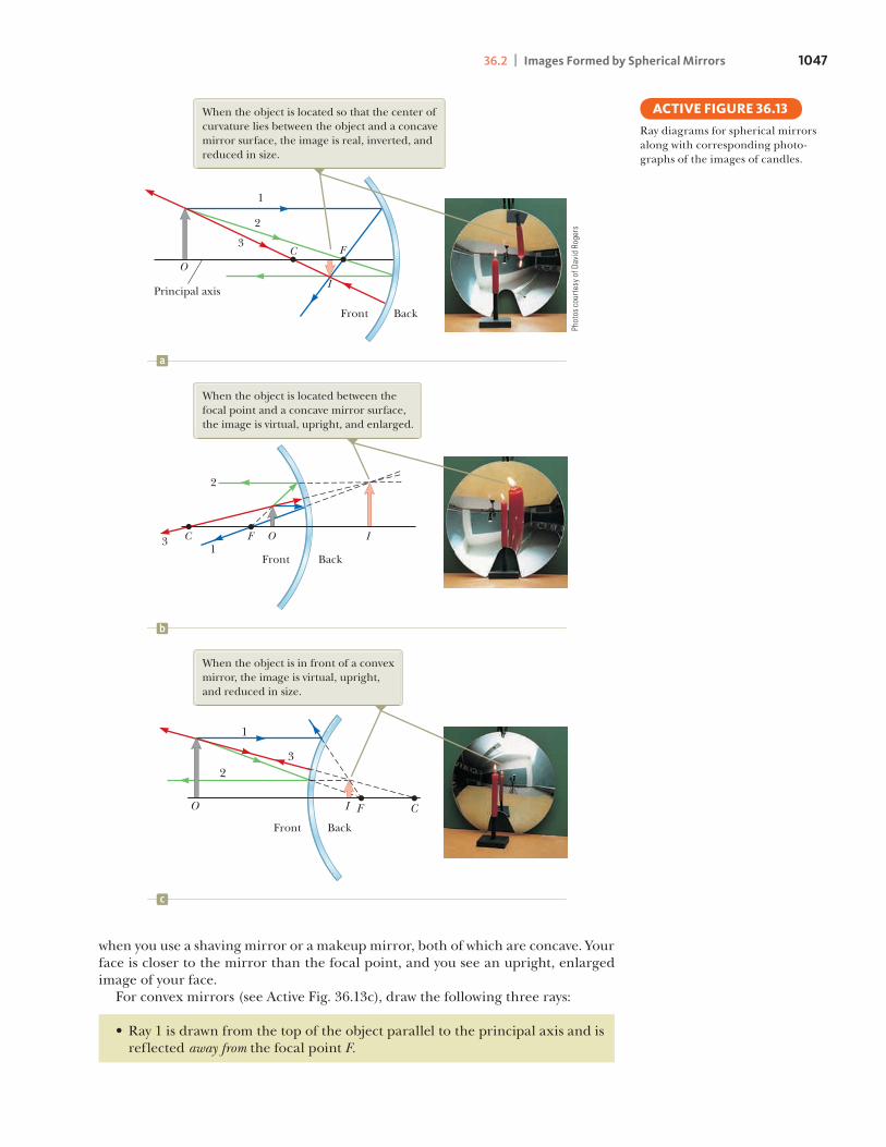
The positions and sizes of images formed by mirrors can be conveniently deter-mined with ray diagrams. These pictorial representations reveal the nature of the image and can be used to check results calculated from the mathematical represen-tation using the mirror and magnification equations. To draw a ray diagram, you must know the position of the object and the locations of the mirror’s focal point and center of curvature. You then draw three rays to locate the image as shown by the examples in Active Figure 36.13. These rays all start from the same object point and are drawn as follows. You may choose any point on the object; here, let’s choose the top of the object for simplicity. For concave mirrors (see Active Figs. 36.13a and 36.13b), draw the following three rays:
• Ray 1 is drawn from the top of the object parallel to the principal axis and is reflected through the focal point F.
• Ray 2 is drawn from the top of the object through the focal point (or as if coming from the focal point if p , f) and is reflected parallel to the principal axis.
• Ray 3 is drawn from the top of the object through the center of curvature C (or as if coming from the center C if p , f) and is reflected back on itself.
The intersection of any two of these rays locates the image. The third ray serves as a check of the construction. The image point obtained in this fashion must always agree with the value of q calculated from the mirror equation. With concave mirrors, notice what happens as the object is moved closer to the mirror. The real, inverted image in Active Figure 36.13a moves to the left and becomes larger as the object approaches the focal point. When the object is at the focal point, the image is infinitely far to the left. When the object lies between the focal point and the mirror surface as shown in Active Figure 36.13b, however, the image is to the right, behind the object, and virtual, upright, and enlarged. This latter situation applies
Front, orreal, side
Reflected light
Back, orvirtual, side
No lightIncident light
Flat, convex, or concavemirrored surface
p and q positive p and q negative
Figure 36.12 Signs of p and q for convex and concave mirrors.
Sign Conventions for MirrorsQuantity Positive When . . . Negative When . . .
Object location (p) object is in front of mirror object is in back of mirror (real object). (virtual object). Image location (q) image is in front of mirror image is in back of mirror (real image). (virtual image).Image height (h9) image is upright. image is inverted.Focal length ( f ) and radius (R) mirror is concave. mirror is convex.Magnification (M) image is upright. image is inverted.
TABLE 36.1Pitfall Prevention 36.3Watch Your SignsSuccess in working mirror prob-lems (as well as problems involving refracting surfaces and thin lenses) is largely determined by proper sign choices when substituting into the equations. The best way to success is to work a multitude of problems on your own.
Pitfall Prevention 36.4Choose a Small Number of RaysA huge number of light rays leave each point on an object (and pass through each point on an image). In a ray diagram, which displays the characteristics of the image, we choose only a few rays that follow simply stated rules. Locating the image by calculation complements the diagram.
36.2 | Images Formed by Spherical Mirrors 1047
when you use a shaving mirror or a makeup mirror, both of which are concave. Your face is closer to the mirror than the focal point, and you see an upright, enlarged image of your face. For convex mirrors (see Active Fig. 36.13c), draw the following three rays:
• Ray 1 is drawn from the top of the object parallel to the principal axis and is reflected away from the focal point F.
Ray diagrams for spherical mirrors along with corresponding photo-graphs of the images of candles.
ACTIVE FIGURE 36.13
1
2
3 C F O I
CFO I
1
23
Front Back
Front Back
Front Back
a
b
c
When the object is located between the focal point and a concave mirror surface, the image is virtual, upright, and enlarged.
When the object is in front of a convex mirror, the image is virtual, upright, and reduced in size.
FCO
IPrincipal axis
1
2
3
When the object is located so that the center of curvature lies between the object and a concave mirror surface, the image is real, inverted, and reduced in size.
Phot
os c
ourt
esy
of D
avid
Rog
ers

1048 CHAPTER 36 | Image Formation
• Ray 2 is drawn from the top of the object toward the focal point on the back side of the mirror and is reflected parallel to the principal axis.
• Ray 3 is drawn from the top of the object toward the center of curvature C on the back side of the mirror and is reflected back on itself.
In a convex mirror, the image of an object is always virtual, upright, and reduced in size as shown in Active Figure 36.13c. In this case, as the object distance decreases, the virtual image increases in size and moves away from the focal point toward the mirror as the object approaches the mirror. You should construct other diagrams to verify how image position varies with object position.
Quick Quiz 36.2 You wish to start a fire by reflecting sunlight from a mirror onto some paper under a pile of wood. Which would be the best choice for the type of mirror? (a) flat (b) concave (c) convex
Quick Quiz 36.3 Consider the image in the mirror in Figure 36.14. Based on the appearance of this image, would you conclude that (a) the mirror is con-cave and the image is real, (b) the mirror is concave and the image is virtual, (c) the mirror is convex and the image is real, or (d) the mirror is convex and the image is virtual?Figure 36.14 (Quick Quiz 36.3)
What type of mirror is shown here?
NAS
A
Example 36.3 The Image Formed by a Concave Mirror
A spherical mirror has a focal length of 110.0 cm.
(A) Locate and describe the image for an object distance of 25.0 cm.
SOLUTION
Conceptualize Because the focal length of the mirror is positive, it is a concave mirror (see Table 36.1). We expect the possibilities of both real and virtual images.
Categorize Because the object distance in this part of the problem is larger than the focal length, we expect the image to be real. This situation is analogous to that in Active Figure 36.13a.
Find the magnification of the image from Equation 36.2: M 5 2q
p5 2
16.7 cm25.0 cm
5 20.667
Analyze Find the image distance by using Equation 36.6:
1q5
1f2
1p
1q5
110.0 cm
21
25.0 cm
q 5 16.7 cm
Finalize The absolute value of M is less than unity, so the image is smaller than the object, and the negative sign for M tells us that the image is inverted. Because q is positive, the image is located on the front side of the mirror and is real. Look into the bowl of a shiny spoon or stand far away from a shaving mirror to see this image.
(B) Locate and describe the image for an object distance of 10.0 cm.
SOLUTION
Categorize Because the object is at the focal point, we expect the image to be infinitely far away.

36.2 | Images Formed by Spherical Mirrors 1049
36.3 cont.
Finalize This result means that rays originating from an object positioned at the focal point of a mirror are reflected so that the image is formed at an infinite distance from the mirror; that is, the rays travel parallel to one another after reflection. Such is the situation in a flashlight or an automobile headlight, where the bulb filament is placed at the focal point of a reflector, producing a parallel beam of light.
(C) Locate and describe the image for an object distance of 5.00 cm.
SOLUTION
Categorize Because the object distance is smaller than the focal length, we expect the image to be virtual. This situation is analogous to that in Active Figure 36.13b.
Analyze Find the image distance by using Equation 36.6:
1q5
1f2
1p
1q5
110.0 cm
21
10.0 cm
q 5 `
Find the magnification of the image from Equation 36.2: M 5 2q
p5 2a210.0 cm
5.00 cmb 5 12.00
Analyze Find the image distance by using Equation 36.6:
1q5
1f2
1p
1q5
110.0 cm
21
5.00 cm
q 5 210.0 cm
Finalize The image is twice as large as the object, and the positive sign for M indicates that the image is upright (see Active Fig. 36.13b). The negative value of the image distance tells us that the image is virtual, as expected. Put your face close to a shaving mirror to see this type of image.
WHAT IF? Suppose you set up the candle and mirror apparatus illustrated in Active Figure 36.13a and described here in part (A). While adjusting the apparatus, you accidentally bump the candle and it begins to slide toward the mirror at velocity vp. How fast does the image of the candle move?
Substitute numerical values from part (A): vq 5 2110.0 cm 22 vp
125.0 cm 2 10.0 cm 22 5 20.444vp
Differentiate this equation with respect to time to find the velocity of the image:
(1) vq 5dq
dt5
ddta fp
p 2 fb 5 2
f 2
1p 2 f 22 dp
dt5 2
f 2vp
1p 2 f 22
Answer Solve the mirror equation, Equation 36.6, for q :
q 5fp
p 2 f
Therefore, the speed of the image is less than that of the object in this case. We can see two interesting behaviors of the function for vq in Equation (1). First, the velocity is negative regard-less of the value of p or f. Therefore, if the object moves toward the mirror, the image moves toward the left in Active Figure 36.13 without regard for the side of the focal point at which the object is located or whether the mir-ror is concave or convex. Second, in the limit of p S 0, the velocity vq approaches 2vp. As the object moves very close to the mirror, the mirror looks like a plane mirror, the image is as far behind the mirror as the object is in front, and both the object and the image move with the same speed.

1050 CHAPTER 36 | Image Formation
Example 36.4 The Image Formed by a Convex Mirror
An automobile rearview mirror as shown in Figure 36.15 shows an image of a truck located 10.0 m from the mirror. The focal length of the mirror is 20.60 m.
(A) Find the position of the image of the truck.
SOLUTION
Conceptualize This situation is depicted in Active Figure 36.13c.
Categorize Because the mirror is convex, we expect it to form an upright, reduced, virtual image for any object position.
. B
o Za
unde
rs/C
orbi
s
Figure 36.15 (Example 36.4) An approaching truck is seen in a convex mirror on the right side of an auto-mobile. Notice that the image of the truck is in focus, but the frame of the mirror is not, which demonstrates that the image is not at the same loca-tion as the mirror surface.
Analyze Find the image distance by using Equation 36.6:
1q5
1f2
1p
1q5
120.60 m
21
10.0 m
q 5 20.57 m
(B) Find the magnification of the image.
SOLUTION
Analyze Use Equation 36.2: M 5 2q
p5 2a20.57 m
10.0 mb 5 10.057
Finalize The negative value of q in part (A) indicates that the image is virtual, or behind the mirror, as shown in Active Figure 36.13c. The magnification in part (B) indicates that the image is much smaller than the truck and is upright because M is positive. The image is reduced in size, so the truck appears to be farther away than it actually is. Because of the image’s small size, these mirrors carry the inscription, “Objects in this mirror are closer than they appear.” Look into your rearview mirror or the back side of a shiny spoon to see an image of this type.
36.3 Images Formed by RefractionIn this section, we describe how images are formed when light rays follow the wave under refraction model at the boundary between two transparent materials. Consider two transparent media having indices of refraction n1 and n2, where the boundary between the two media is a spherical surface of radius R (Fig. 36.16). We assume the object at O is in the medium for which the index of refraction is n1. Let’s consider the paraxial rays leaving O. As we shall see, all such rays are refracted at the spherical surface and focus at a single point I, the image point. Figure 36.17 shows a single ray leaving point O and refracting to point I. Snell’s law of refraction applied to this ray gives
n1 sin u1 5 n2 sin u2
Because u1 and u2 are assumed to be small, we can use the small-angle approxima-tion sin u < u (with angles in radians) and write Snell’s law as
n1u1 5 n2u2
n1 � n2
O I
n2n1 R
p q
Rays making small angles with the principal axis diverge from a point object at O and are refracted through the image point I.
Figure 36.16 An image formed by refraction at a spherical surface.

36.3 | Images Formed by Refraction 1051
We know that an exterior angle of any triangle equals the sum of the two opposite interior angles, so applying this rule to triangles OPC and PIC in Figure 36.17 gives
u1 5 a 1 b
b 5 u2 1 g
Combining all three expressions and eliminating u1 and u2 gives
n1a 1 n2g 5 (n2 2 n1)b (36.7)
Figure 36.17 shows three right triangles that have a common vertical leg of length d. For paraxial rays (unlike the relatively large-angle ray shown in Fig. 36.17), the horizontal legs of these triangles are approximately p for the triangle containing angle a, R for the triangle containing angle b, and q for the triangle containing angle g. In the small-angle approximation, tan u < u, so we can write the approxi-mate relationships from these triangles as follows:
tan a < a <dp
tan b < b <dR
tan g < g <dq
Substituting these expressions into Equation 36.7 and dividing through by d gives
n 1
p1
n 2
q5
n 2 2 n 1
R (36.8)
For a fixed object distance p, the image distance q is independent of the angle the ray makes with the axis. This result tells us that all paraxial rays focus at the same point I. As with mirrors, we must use a sign convention to apply Equation 36.8 to a variety of cases. We define the side of the surface in which light rays originate as the front side. The other side is called the back side. In contrast with mirrors, where real images are formed in front of the reflecting surface, real images are formed by refraction of light rays to the back of the surface. Because of the difference in location of real images, the refraction sign conventions for q and R are opposite the reflection sign conventions. For example, q and R are both positive in Figure 36.17. The sign conven-tions for spherical refracting surfaces are summarized in Table 36.2.
Relation between object and image distance for a refracting surface
n2n1
p q
O
P
R
C
d
a
I
b g
u2
u1
Figure 36.17 Geometry used to derive Equation 36.8, assuming n1 , n2.
Sign Conventions for Refracting SurfacesQuantity Positive When . . . Negative When . . .
Object location (p) object is in front of surface object is in back of surface (real object). (virtual object).Image location (q) image is in back of surface image is in front of surface (real image). (virtual image).Image height (h9) image is upright. image is inverted.Radius (R) center of curvature is center of curvature is in back of surface. in front of surface.
TABLE 36.2

1052 CHAPTER 36 | Image Formation
We derived Equation 36.8 from an assumption that n1 , n2 in Figure 36.17. This assumption is not necessary, however. Equation 36.8 is valid regardless of which index of refraction is greater.
Flat Refracting Surfaces
If a refracting surface is flat, then R is infinite and Equation 36.8 reduces to
n 1
p5 2
n 2
q
q 5 2n 2
n 1 p (36.9)
From this expression, we see that the sign of q is opposite that of p. Therefore, according to Table 36.2, the image formed by a flat refracting surface is on the same side of the surface as the object as illustrated in Active Figure 36.18 for the situation in which the object is in the medium of index n1 and n1 is greater than n2. In this case, a virtual image is formed between the object and the surface. If n1 is less than n2, the rays on the back side diverge from one another at lesser angles than those in Active Figure 36.18. As a result, the virtual image is formed to the left of the object.
Quick Quiz 36.4 In Figure 36.16, what happens to the image point I as the object point O is moved to the right from very far away to very close to the refracting surface? (a) It is always to the right of the surface. (b) It is always to the left of the surface. (c) It starts off to the left, and at some position of O, I moves to the right of the surface. (d) It starts off to the right, and at some position of O, I moves to the left of the surface.
Quick Quiz 36.5 In Active Figure 36.18, what happens to the image point I as the object point O moves toward the right-hand surface of the material of index of refraction n1? (a) It always remains between O and the surface, arriv-ing at the surface just as O does. (b) It moves toward the surface more slowly than O so that eventually O passes I. (c) It approaches the surface and then moves to the right of the surface.
p
q
O
The image is virtual and on the same side of the surface as the object.
n1 � n2n1 n2
The image formed by a flat refract-ing surface. All rays are assumed to be paraxial.
ACTIVE FIGURE 36.18
Conceptual Example 36.5 Let’s Go Scuba Diving!
Objects viewed under water with the naked eye appear blurred and out of focus. A scuba diver using a mask, however, has a clear view of underwater objects. Explain how that works, using the information that the indices of refraction of the cornea, water, and air are 1.376, 1.333, and 1.000 29, respectively.
SOLUTIONBecause the cornea and water have almost identical indices of refraction, very little refraction occurs when a person under water views objects with the naked eye. In this case, light rays from an object focus behind the retina, resulting in a blurred image. When a mask is used, however, the air space between the eye and the mask surface provides the normal amount of refraction at the eye–air interface; consequently, the light from the object focuses on the retina.
36.3 | Images Formed by Refraction 1053
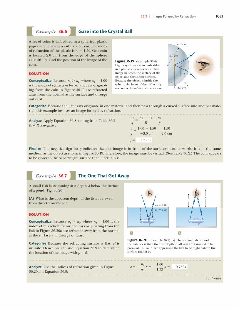
Example 36.6 Gaze into the Crystal Ball
A set of coins is embedded in a spherical plastic paperweight having a radius of 3.0 cm. The index of refraction of the plastic is n1 5 1.50. One coin is located 2.0 cm from the edge of the sphere (Fig. 36.19). Find the position of the image of the coin.
SOLUTION
Conceptualize Because n1 . n2, where n2 5 1.00 is the index of refraction for air, the rays originat-ing from the coin in Figure 36.19 are refracted away from the normal at the surface and diverge outward.
Categorize Because the light rays originate in one material and then pass through a curved surface into another mate-rial, this example involves an image formed by refraction.
3.0 cm
2.0 cm
q
n2n1
n1 � n2
Figure 36.19 (Example 36.6) Light rays from a coin embedded in a plastic sphere form a virtual image between the surface of the object and the sphere surface. Because the object is inside the sphere, the front of the refracting surface is the interior of the sphere.
Analyze Apply Equation 36.8, noting from Table 36.2 that R is negative:
n 2
q5
n 2 2 n 1
R2
n 1
p
1q5
1.00 2 1.5023.0 cm
21.50
2.0 cm
q 5 21.7 cm
Finalize The negative sign for q indicates that the image is in front of the surface; in other words, it is in the same medium as the object as shown in Figure 36.19. Therefore, the image must be virtual. (See Table 36.2.) The coin appears to be closer to the paperweight surface than it actually is.
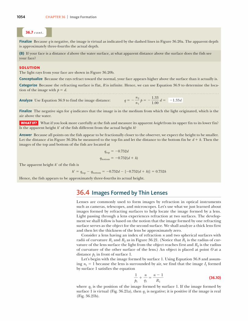
Example 36.7 The One That Got Away
A small fish is swimming at a depth d below the surface of a pond (Fig. 36.20).
(A) What is the apparent depth of the fish as viewed from directly overhead?
SOLUTION
Conceptualize Because n1 . n2, where n2 5 1.00 is the index of refraction for air, the rays originating from the fish in Figure 36.20a are refracted away from the normal at the surface and diverge outward.
Categorize Because the refracting surface is flat, R is infinite. Hence, we can use Equation 36.9 to determine the location of the image with p 5 d.
dq
d
n2 � 1.00
n1 � 1.33q
a b
Figure 36.20 (Example 36.7) (a) The apparent depth q of the fish is less than the true depth d. All rays are assumed to be paraxial. (b) Your face appears to the fish to be higher above the surface than it is.
Analyze Use the indices of refraction given in Figure 36.20a in Equation 36.9:
q 5 2n 2
n 1 p 5 2
1.001.33
d 5 20.752d
continued
1054 CHAPTER 36 | Image Formation
36.7 cont.
Finalize Because q is negative, the image is virtual as indicated by the dashed lines in Figure 36.20a. The apparent depth is approximately three-fourths the actual depth.
(B) If your face is a distance d above the water surface, at what apparent distance above the surface does the fish see your face?
SOLUTIONThe light rays from your face are shown in Figure 36.20b.
Conceptualize Because the rays refract toward the normal, your face appears higher above the surface than it actually is.
Categorize Because the refracting surface is flat, R is infinite. Hence, we can use Equation 36.9 to determine the loca-tion of the image with p 5 d.
Analyze Use Equation 36.9 to find the image distance: q 5 2n 2
n 1 p 5 2
1.331.00
d 5 21.33d
Finalize The negative sign for q indicates that the image is in the medium from which the light originated, which is the air above the water.
WHAT IF? What if you look more carefully at the fish and measure its apparent height from its upper fin to its lower fin? Is the apparent height h9 of the fish different from the actual height h?
Answer Because all points on the fish appear to be fractionally closer to the observer, we expect the height to be smaller. Let the distance d in Figure 36.20a be measured to the top fin and let the distance to the bottom fin be d 1 h. Then the images of the top and bottom of the fish are located at
qtop 5 20.752d
qbottom 5 20.752(d 1 h)
The apparent height h9 of the fish is
h9 5 qtop 2 qbottom 5 20.752d 2 [20.752(d 1 h)] 5 0.752h
Hence, the fish appears to be approximately three-fourths its actual height.
36.4 Images Formed by Thin LensesLenses are commonly used to form images by refraction in optical instruments such as cameras, telescopes, and microscopes. Let’s use what we just learned about images formed by refracting surfaces to help locate the image formed by a lens. Light passing through a lens experiences refraction at two surfaces. The develop-ment we shall follow is based on the notion that the image formed by one refracting surface serves as the object for the second surface. We shall analyze a thick lens first and then let the thickness of the lens be approximately zero. Consider a lens having an index of refraction n and two spherical surfaces with radii of curvature R1 and R2 as in Figure 36.21. (Notice that R1 is the radius of cur-vature of the lens surface the light from the object reaches first and R2 is the radius of curvature of the other surface of the lens.) An object is placed at point O at a distance p1 in front of surface 1. Let’s begin with the image formed by surface 1. Using Equation 36.8 and assum-ing n1 5 1 because the lens is surrounded by air, we find that the image I1 formed by surface 1 satisfies the equation
1p11
nq15
n 2 1R1
(36.10)
where q1 is the position of the image formed by surface 1. If the image formed by surface 1 is virtual (Fig. 36.21a), then q1 is negative; it is positive if the image is real (Fig. 36.21b).

36.4 | Images Formed by Thin Lenses 1055
Now let’s apply Equation 36.8 to surface 2, taking n1 5 n and n2 5 1. (We make this switch in index because the light rays approaching surface 2 are in the material of the lens, and this material has index n.) Taking p2 as the object distance for sur-face 2 and q2 as the image distance gives
np21
1q25
1 2 nR2
(36.11)
We now introduce mathematically that the image formed by the first surface acts as the object for the second surface. If the image from surface 1 is virtual as in Figure 36.21a, we see that p2, measured from surface 2, is related to q1 as p2 5 2q1 1 t, where t is the thickness of the lens. Because q1 is negative, p2 is a positive number. Figure 36.21b shows the case of the image from surface 1 being real. In this situation, q1 is positive and p2 5 2q1 1 t, where the image from surface 1 acts as a virtual object, so p2 is negative. Regardless of the type of image from surface 1, the same equation describes the location of the object for surface 2 based on our sign convention. For a thin lens (one whose thickness is small compared with the radii of curvature), we can neglect t. In this approximation, p2 5 2q1 for either type of image from surface 1. Hence, Equation 36.11 becomes
2nq11
1q25
1 2 nR2
(36.12)
Adding Equations 36.10 and 36.12 gives
1p11
1q25 1n 2 1 2 a 1
R12
1R2b (36.13)
For a thin lens, we can omit the subscripts on p1 and q2 in Equation 36.13 and call the object distance p and the image distance q as in Figure 36.22. Hence, we can write Equation 36.13 as
1p1
1q5 1n 2 1 2 a 1
R12
1R2b (36.14)
This expression relates the image distance q of the image formed by a thin lens to the object distance p and to the lens properties (index of refraction and radii of curvature). It is valid only for paraxial rays and only when the lens thickness is much less than R1 and R2. The focal length f of a thin lens is the image distance that corresponds to an infinite object distance, just as with mirrors. Letting p approach ` and q approach f in Equation 36.14, we see that the inverse of the focal length for a thin lens is
1f5 1n 2 1 2 a 1
R12
1R2b (36.15) Lens-makers’ equation
tp1
q1
p2q1
p1p2
O
I1
C1 C1
Surface 1 Surface 2
R1 R2 R2
nSurface 1 Surface 2
R1
tO
n
I1
n1 � 1
a b
The image due to surface 1 is virtual, so I1 is to the left of the surface.
The image due to surface 1 is real, so I1 is to the right of the surface.
n1 � 1
Figure 36.21 To locate the image formed by a lens, we use the virtual image at I1 formed by surface 1 as the object for the image formed by surface 2. The point C1 is the center of curvature of surface 1.
O
I
R1 R2
C1C2
qp
Figure 36.22 Simplified geometry for a thin lens.

1056 CHAPTER 36 | Image Formation
This relationship is called the lens-makers’ equation because it can be used to determine the values of R1 and R2 needed for a given index of refraction and a desired focal length f. Conversely, if the index of refraction and the radii of curva-ture of a lens are given, this equation can be used to find the focal length. If the lens is immersed in something other than air, this same equation can be used, with n interpreted as the ratio of the index of refraction of the lens material to that of the surrounding fluid. Using Equation 36.15, we can write Equation 36.14 in a form identical to Equa-tion 36.6 for mirrors:
1p1
1q5
1f
(36.16)
This equation, called the thin lens equation, can be used to relate the image dis-tance and object distance for a thin lens. Because light can travel in either direction through a lens, each lens has two focal points, one for light rays passing through in one direction and one for rays passing through in the other direction. These two focal points are illustrated in Figure 36.23 for a plano-convex lens (a converging lens) and a plano-concave lens (a diverging lens). Figure 36.24 is useful for obtaining the signs of p and q, and Table 36.3 gives the sign conventions for thin lenses. These sign conventions are the same as those for refracting surfaces (see Table 36.2). Various lens shapes are shown in Figure 36.25. Notice that a converging lens is thicker at the center than at the edge, whereas a diverging lens is thinner at the center than at the edge.
Magnification of Images
Consider a thin lens through which light rays from an object pass. As with mirrors (Eq. 36.2), a geometric construction shows that the lateral magnification of the image is
M 5h rh5 2
q
p (36.17)
a b
f f f f
F1 F2 F2F1 F2 F2F1F1
Figure 36.23 Parallel light rays pass through (a) a converging lens and (b) a diverging lens. The focal length is the same for light rays pass-ing through a given lens in either direction. Both focal points F1 and F2 are the same distance from the lens.
Pitfall Prevention 36.5A Lens Has Two Focal Points but Only One Focal LengthA lens has a focal point on each side, front and back. There is only one focal length, however; each of the two focal points is located the same distance from the lens (Fig. 36.23). As a result, the lens forms an image of an object at the same point if it is turned around. In practice, that might not happen because real lenses are not infinitesimally thin.
Front, or virtual, side
Incident light
Back, orreal, side
p negativeq positive
p positiveq negative
Refracted light
Converging or diverging lens
Figure 36.24 A diagram for obtaining the signs of p and q for a thin lens. (This diagram also applies to a refracting surface.)
Sign Conventions for Thin LensesQuantity Positive When . . . Negative When . . .
Object location (p) object is in front of lens object is in back of lens (real object). (virtual object).Image location (q) image is in back of lens image is in front of lens (real image). (virtual image).Image height (h9) image is upright. image is inverted.R1 and R2 center of curvature is in back center of curvature is in front of lens. of lens.Focal length (f ) a converging lens. a diverging lens.
TABLE 36.3

36.4 | Images Formed by Thin Lenses 1057
From this expression, it follows that when M is positive, the image is upright and on the same side of the lens as the object. When M is negative, the image is inverted and on the side of the lens opposite the object.
Ray Diagrams for Thin Lenses
Ray diagrams are convenient for locating the images formed by thin lenses or sys-tems of lenses. They also help clarify our sign conventions. Active Figure 36.26 shows such diagrams for three single-lens situations. To locate the image of a converging lens (Active Figs. 36.26a and 36.26b), the fol-lowing three rays are drawn from the top of the object:
• Ray 1 is drawn parallel to the principal axis. After being refracted by the lens, this ray passes through the focal point on the back side of the lens.
• Ray 2 is drawn through the focal point on the front side of the lens (or as if coming from the focal point if p , f) and emerges from the lens parallel to the principal axis.
• Ray 3 is drawn through the center of the lens and continues in a straight line.
To locate the image of a diverging lens (Active Fig. 36.26c), the following three rays are drawn from the top of the object:
• Ray 1 is drawn parallel to the principal axis. After being refracted by the lens, this ray emerges directed away from the focal point on the front side of the lens.
• Ray 2 is drawn in the direction toward the focal point on the back side of the lens and emerges from the lens parallel to the principal axis.
• Ray 3 is drawn through the center of the lens and continues in a straight line.
For the converging lens in Active Figure 36.26a, where the object is to the left of the focal point (p . f ), the image is real and inverted. When the object is between the focal point and the lens (p , f ) as in Active Figure 36.26b, the image is virtual and upright. In that case, the lens acts as a magnifying glass, which we study in more detail in Section 36.8. For a diverging lens (Active Fig. 36.26c), the image is always virtual and upright, regardless of where the object is placed. These geomet-ric constructions are reasonably accurate only if the distance between the rays and the principal axis is much less than the radii of the lens surfaces. Refraction occurs only at the surfaces of the lens. A certain lens design takes advantage of this behavior to produce the Fresnel lens, a powerful lens without great
Plano-convex
Convex-concave
Biconvex
Biconcave Convex-concave
Plano-concave
Figure 36.25 Various lens shapes. (a) Converging lenses have a positive focal length and are thickest at the middle. (b) Diverging lenses have a negative focal length and are thick-est at the edges.
a cb
O F1
Front
I
1
23
I
Front BackBack
O
1
3
2
O
Front Back
I
1
3
2F2
F1
F2 F2
F1
When the object is in front of and outside the focal point of a converging lens, the image is real, inverted, and on the back side of the lens.
When the object is between the focal point and a converging lens, the image is virtual, upright, larger than the object, and on the front side of the lens.
When an object is anywhere in front of a diverging lens, the image is virtual, upright, smaller than the object, and on the front side of the lens.
Ray diagrams for locating the image formed by a thin lens.
ACTIVE FIGURE 36.26

1058 CHAPTER 36 | Image Formation
thickness. Because only the surface curvature is important in the refracting quali-ties of the lens, material in the middle of a Fresnel lens is removed as shown in the cross sections of lenses in Figure 36.27. Because the edges of the curved segments cause some distortion, Fresnel lenses are generally used only in situations in which image quality is less important than reduction of weight. A classroom overhead pro-jector often uses a Fresnel lens; the circular edges between segments of the lens can be seen by looking closely at the light projected onto a screen.
Quick Quiz 36.6 What is the focal length of a pane of window glass? (a) zero (b) infinity (c) the thickness of the glass (d) impossible to determine
Example 36.8 Images Formed by a Converging Lens
A converging lens has a focal length of 10.0 cm.
(A) An object is placed 30.0 cm from the lens. Construct a ray diagram, find the image distance, and describe the image.
SOLUTION
Conceptualize Because the lens is converging, the focal length is pos-itive (see Table 36.3). We expect the possibilities of both real and virtual images.
Categorize Because the object distance is larger than the focal length, we expect the image to be real. The ray diagram for this situ-ation is shown in Figure 36.28a.
a b
O F1
F2 I
15.0 cm
30.0 cm
10.0 cm
O F2I, F1
10.0 cm5.00 cm
10.0 cm
The object is farther from the lens than the focal point.
The object is closer to the lens than the focal point.
Figure 36.28 (Example 36.8) An image is formed by a converging lens.
Analyze Find the image distance by using Equation 36.16:
1q5
1f2
1p
1q5
110.0 cm
21
30.0 cm
q 5 115.0 cm
Figure 36.27 A side view of the construction of a Fresnel lens. (a) The thick lens refracts a light ray as shown. (b) Lens material in the bulk of the lens is cut away, leav-ing only the material close to the curved surface. (c) The small pieces of remaining material are moved to the left to form a flat surface on the left of the Fresnel lens with ridges on the right surface. From a front view, these ridges would be circular in shape. This new lens refracts light in the same way as the lens in (a). (d) A Fresnel lens used in a lighthouse shows several segments with the ridges discussed in (c).
a c db
© O
wen
Fra
nken
/Cor
bis

36.8 cont.
36.4 | Images Formed by Thin Lenses 1059
Finalize The positive sign for the image distance tells us that the image is indeed real and on the back side of the lens. The magnification of the image tells us that the image is reduced in height by one half, and the negative sign for M tells us that the image is inverted.
(B) An object is placed 10.0 cm from the lens. Find the image distance and describe the image.
SOLUTION
Categorize Because the object is at the focal point, we expect the image to be infinitely far away.
Find the magnification of the image from Equation 36.17: M 5 2
q
p5 2
15.0 cm30.0 cm
5 20.500
Analyze Find the image distance by using Equation 36.16:
1q5
1f2
1p
1q5
110.0 cm
21
10.0 cm
q 5 `
Finalize This result means that rays originating from an object positioned at the focal point of a lens are refracted so that the image is formed at an infinite distance from the lens; that is, the rays travel parallel to one another after refraction.
(C) An object is placed 5.00 cm from the lens. Construct a ray diagram, find the image distance, and describe the image.
SOLUTION
Categorize Because the object distance is smaller than the focal length, we expect the image to be virtual. The ray dia-gram for this situation is shown in Figure 36.28b.
Analyze Find the image distance by using Equation 36.16:
1q5
1f2
1p
1q5
110.0 cm
21
5.00 cm
q 5 210.0 cm
Find the magnification of the image from Equation 36.17: M 5 2
q
p5 2a210.0 cm
5.00 cmb 5 12.00
Finalize The negative image distance tells us that the image is virtual and formed on the side of the lens from which the light is incident, the front side. The image is enlarged, and the positive sign for M tells us that the image is upright.
WHAT IF? What if the object moves right up to the lens surface so that p S 0? Where is the image?
Answer In this case, because p ,, R, where R is either of the radii of the surfaces of the lens, the curvature of the lens can be ignored. The lens should appear to have the same effect as a flat piece of material, which suggests that the image is just on the front side of the lens, at q 5 0. This conclusion can be verified mathematically by rearranging the thin lens equation:
1q5
1f2
1p
If we let p S 0, the second term on the right becomes very large compared with the first and we can neglect 1/f. The equation becomes
1q5 2
1p
S q 5 2p 5 0
Therefore, q is on the front side of the lens (because it has the opposite sign as p) and right at the lens surface.

1060 CHAPTER 36 | Image Formation
Example 36.9 Images Formed by a Diverging Lens
A diverging lens has a focal length of 10.0 cm.
(A) An object is placed 30.0 cm from the lens. Construct a ray diagram, find the image distance, and describe the image.
SOLUTION
Conceptualize Because the lens is diverging, the focal length is negative (see Table 36.3). The ray diagram for this situa-tion is shown in Figure 36.29a.
a cb
IOF1
5.00 cm
3.33 cm
F2IO F1
30.0 cm
10.0 cm
7.50 cm
F2 IO, F1
5.00 cm
10.0 cm10.0 cm
F2
The object is farther from the lens than the focal point.The object is farther from the lens than the focal point.
The object is closer to the lens than the focal point.
The object is at the focal point.
Figure 36.29 (Example 36.9) An image is formed by a diverging lens.
Categorize Because the lens is diverging, we expect it to form an upright, reduced, virtual image for any object position.
Find the magnification of the image from Equation 36.17:
M 5 2q
p5 2a27.50 cm
30.0 cmb 5 10.250
Analyze Find the image distance by using Equation 36.16:
1q5
1f2
1p
1q5
1210.0 cm
21
30.0 cm
q 5 27.50 cm
Finalize This result confirms that the image is virtual, smaller than the object, and upright. Look through the diverging lens in a door peephole to see this type of image.
(B) An object is placed 10.0 cm from the lens. Construct a ray diagram, find the image distance, and describe the image.
SOLUTIONThe ray diagram for this situation is shown in Figure 36.29b.
Analyze Find the image distance by using Equation 36.16:
1q5
1f2
1p
1q5
1210.0 cm
21
10.0 cm
q 5 25.00 cm

36.9 cont.
36.4 | Images Formed by Thin Lenses 1061
Combination of Thin Lenses
If two thin lenses are used to form an image, the system can be treated in the fol-lowing manner. First, the image formed by the first lens is located as if the second lens were not present. Then a ray diagram is drawn for the second lens, with the image formed by the first lens now serving as the object for the second lens. The second image formed is the final image of the system. If the image formed by the first lens lies on the back side of the second lens, that image is treated as a vir-tual object for the second lens (that is, in the thin lens equation, p is negative). The same procedure can be extended to a system of three or more lenses. Because the magnification due to the second lens is performed on the magnified image due to the first lens, the overall magnification of the image due to the combination of lenses is the product of the individual magnifications:
M 5 M1M2 (36.18)
This equation can be used for combinations of any optical elements such as a lens and a mirror. For more than two optical elements, the magnifications due to all ele-ments are multiplied together. Let’s consider the special case of a system of two lenses of focal lengths f1 and f2 in contact with each other. If p1 5 p is the object distance for the combination, application of the thin lens equation (Eq. 36.16) to the first lens gives
1p1
1q15
1f1
where q1 is the image distance for the first lens. Treating this image as the object for the second lens, we see that the object distance for the second lens must be p2 5 2q1. (The distances are the same because the lenses are in contact and assumed to be infinitesimally thin. The object distance is negative because the object is virtual if the image from the first lens is real.) Therefore, for the second lens,
1p21
1q25
1f2
S 21q11
1q5
1f2
Find the magnification of the image from Equation 36.17:
M 5 2q
p5 2a25.00 cm
10.0 cmb 5 10.500
Finalize Notice the difference between this situation and that for a converging lens. For a diverging lens, an object at the focal point does not produce an image infinitely far away.
(C) An object is placed 5.00 cm from the lens. Construct a ray diagram, find the image distance, and describe the image.
SOLUTIONThe ray diagram for this situation is shown in Figure 36.29c.
Find the magnification of the image from Equation 36.17:
M 5 2a23.33 cm5.00 cm
b 5 10.667
Analyze Find the image distance by using Equation 36.16:
1q5
1f2
1p
1q5
1210.0 cm
21
5.0 cm
q 5 23.33 cm
Finalize For all three object positions, the image position is negative and the magnification is a positive number smaller than 1, which confirms that the image is virtual, smaller than the object, and upright.
1062 CHAPTER 36 | Image Formation
where q 5 q2 is the final image distance from the second lens, which is the image distance for the combination. Adding the equations for the two lenses eliminates q1 and gives
1p1
1q5
1f11
1f2
If the combination is replaced with a single lens that forms an image at the same location, its focal length must be related to the individual focal lengths by the expression
1f5
1f11
1f2
(36.19)
Therefore, two thin lenses in contact with each other are equivalent to a single thin lens having a focal length given by Equation 36.19.
Focal length for a combination of two thin
lenses in contact
Example 36.10 Where Is the Final Image?
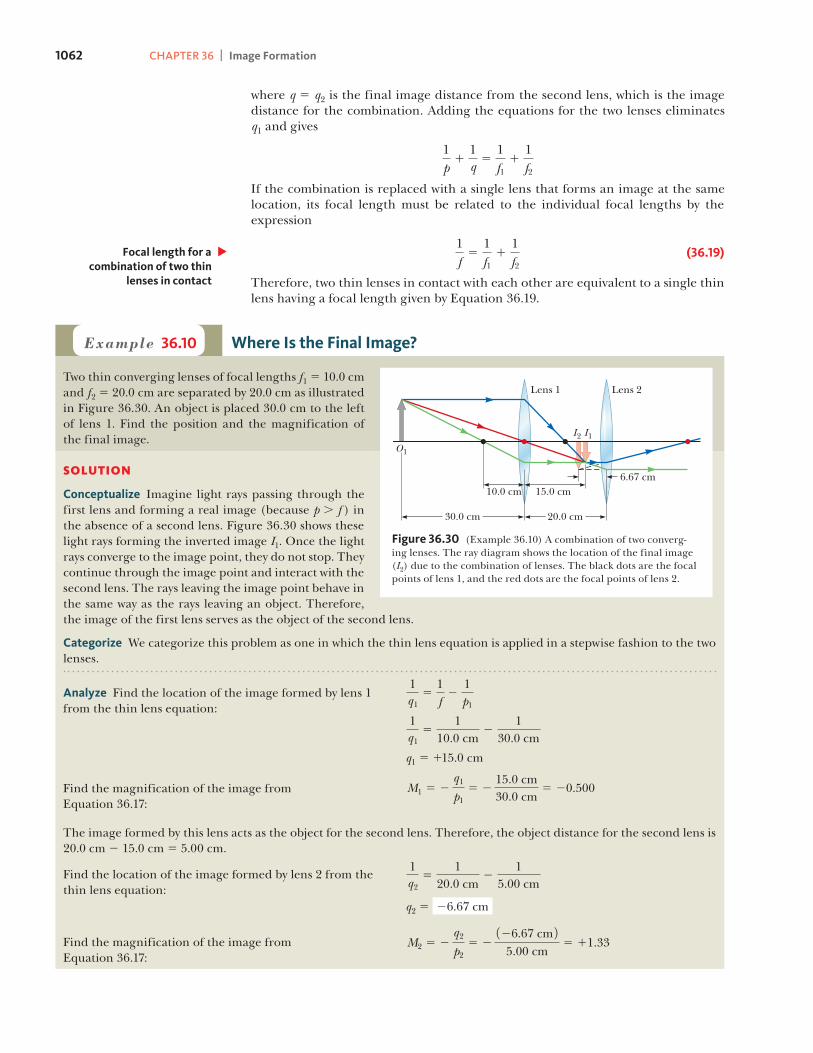
Two thin converging lenses of focal lengths f1 5 10.0 cm and f2 5 20.0 cm are separated by 20.0 cm as illustrated in Figure 36.30. An object is placed 30.0 cm to the left of lens 1. Find the position and the magnification of the final image.
SOLUTION
Conceptualize Imagine light rays passing through the first lens and forming a real image (because p . f ) in the absence of a second lens. Figure 36.30 shows these light rays forming the inverted image I1. Once the light rays converge to the image point, they do not stop. They continue through the image point and interact with the second lens. The rays leaving the image point behave in the same way as the rays leaving an object. Therefore, the image of the first lens serves as the object of the second lens.
Categorize We categorize this problem as one in which the thin lens equation is applied in a stepwise fashion to the two lenses.
O1
Lens 1 Lens 2
20.0 cm
6.67 cm15.0 cm10.0 cm
30.0 cm
I1I2
Figure 36.30 (Example 36.10) A combination of two converg-ing lenses. The ray diagram shows the location of the final image (I2) due to the combination of lenses. The black dots are the focal points of lens 1, and the red dots are the focal points of lens 2.
Find the magnification of the image from Equation 36.17:
M1 5 2q1
p15 2
15.0 cm30.0 cm
5 20.500
Analyze Find the location of the image formed by lens 1 from the thin lens equation:
1q15
1f2
1p1
1q15
110.0 cm
21
30.0 cm
q1 5 115.0 cm
The image formed by this lens acts as the object for the second lens. Therefore, the object distance for the second lens is 20.0 cm 2 15.0 cm 5 5.00 cm.
Find the location of the image formed by lens 2 from the thin lens equation:
1q25
120.0 cm
21
5.00 cm
q2 5 26.67 cm
Find the magnification of the image from Equation 36.17:
M2 5 2q2
p25 2
126.67 cm 25.00 cm
5 11.33
36.5 | Lens Aberrations 1063
36.10 cont.
36.5 Lens AberrationsOur analysis of mirrors and lenses assumes rays make small angles with the princi-pal axis and the lenses are thin. In this simple model, all rays leaving a point source focus at a single point, producing a sharp image. Clearly, that is not always true. When the approximations used in this analysis do not hold, imperfect images are formed. A precise analysis of image formation requires tracing each ray, using Snell’s law at each refracting surface and the law of reflection at each reflecting surface. This procedure shows that the rays from a point object do not focus at a single point, with the result that the image is blurred. The departures of actual images from the ideal predicted by our simplified model are called aberrations.
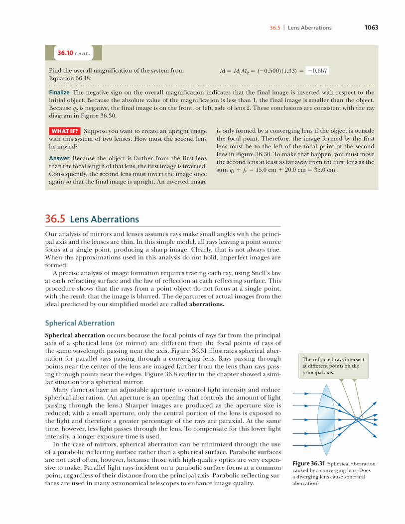
Spherical Aberration
Spherical aberration occurs because the focal points of rays far from the principal axis of a spherical lens (or mirror) are different from the focal points of rays of the same wavelength passing near the axis. Figure 36.31 illustrates spherical aber-ration for parallel rays passing through a converging lens. Rays passing through points near the center of the lens are imaged farther from the lens than rays pass-ing through points near the edges. Figure 36.8 earlier in the chapter showed a simi-lar situation for a spherical mirror. Many cameras have an adjustable aperture to control light intensity and reduce spherical aberration. (An aperture is an opening that controls the amount of light passing through the lens.) Sharper images are produced as the aperture size is reduced; with a small aperture, only the central portion of the lens is exposed to the light and therefore a greater percentage of the rays are paraxial. At the same time, however, less light passes through the lens. To compensate for this lower light intensity, a longer exposure time is used. In the case of mirrors, spherical aberration can be minimized through the use of a parabolic reflecting surface rather than a spherical surface. Parabolic surfaces are not used often, however, because those with high-quality optics are very expen-sive to make. Parallel light rays incident on a parabolic surface focus at a common point, regardless of their distance from the principal axis. Parabolic reflecting sur-faces are used in many astronomical telescopes to enhance image quality.
Find the overall magnification of the system from Equation 36.18:
M 5 M1M2 5 (20.500)(1.33) 5 20.667
WHAT IF? Suppose you want to create an upright image with this system of two lenses. How must the second lens be moved?
Answer Because the object is farther from the first lens than the focal length of that lens, the first image is inverted. Consequently, the second lens must invert the image once again so that the final image is upright. An inverted image
is only formed by a converging lens if the object is outside the focal point. Therefore, the image formed by the first lens must be to the left of the focal point of the second lens in Figure 36.30. To make that happen, you must move the second lens at least as far away from the first lens as the sum q1 1 f2 5 15.0 cm 1 20.0 cm 5 35.0 cm.
Finalize The negative sign on the overall magnification indicates that the final image is inverted with respect to the initial object. Because the absolute value of the magnification is less than 1, the final image is smaller than the object. Because q2 is negative, the final image is on the front, or left, side of lens 2. These conclusions are consistent with the ray diagram in Figure 36.30.
The refracted rays intersect at different points on the principal axis.
Figure 36.31 Spherical aberration caused by a converging lens. Does a diverging lens cause spherical aberration?

1064 CHAPTER 36 | Image Formation
Chromatic Aberration
In Chapter 35, we described dispersion, whereby a material’s index of refraction varies with wavelength. Because of this phenomenon, violet rays are refracted more than red rays when white light passes through a lens (Fig. 36.32). The figure shows that the focal length of a lens is greater for red light than for violet light. Other wave-lengths (not shown in Fig. 36.32) have focal points intermediate between those of red and violet, which causes a blurred image and is called chromatic aberration. Chromatic aberration for a diverging lens also results in a shorter focal length for violet light than for red light, but on the front side of the lens. Chromatic aber-ration can be greatly reduced by combining a converging lens made of one type of glass and a diverging lens made of another type of glass.
36.6 The CameraThe photographic camera is a simple optical instrument whose essential features are shown in Figure 36.33. It consists of a light-tight chamber, a converging lens that produces a real image, and a light-sensitive component behind the lens on which the image is formed. The image in a digital camera is formed on a charge-coupled device (CCD), which digitizes the image, turning it into binary code. (A CCD is described in Section 40.2.) The digital information is then stored on a memory chip for playback on the camera’s display screen, or it can be downloaded to a computer. Film cameras are similar to digital cameras except that the light forms an image on light-sensitive film rather than on a CCD. The film must then be chemically processed to produce the image on paper. In the discussion that follows, we assume the camera is digital. A camera is focused by varying the distance between the lens and the CCD. For proper focusing—which is necessary for the formation of sharp images—the lens-to-CCD distance depends on the object distance as well as the focal length of the lens. The shutter, positioned behind the lens, is a mechanical device that is opened for selected time intervals, called exposure times. You can photograph moving objects by using short exposure times or photograph dark scenes (with low light levels) by using long exposure times. If this adjustment were not available, it would be impos-sible to take stop-action photographs. For example, a rapidly moving vehicle could move enough in the time interval during which the shutter is open to produce a blurred image. Another major cause of blurred images is the movement of the cam-era while the shutter is open. To prevent such movement, either short exposure times or a tripod should be used, even for stationary objects. Typical shutter speeds (that is, exposure times) are 1
30 s, 1
60 s, 1
125 s, and 1250 s. In practice, stationary objects
are normally shot with an intermediate shutter speed of 160 s.
The intensity I of the light reaching the CCD is proportional to the area of the lens. Because this area is proportional to the square of the diameter D, it follows that I is also proportional to D 2. Light intensity is a measure of the rate at which energy is received by the CCD per unit area of the image. Because the area of the image is proportional to q 2 and q < f (when p .. f, so p can be approximated as infinite), we conclude that the intensity is also proportional to 1/f 2 and therefore that I ~ D2/f 2. The ratio f/D is called the f -number of a lens:
f-number ;f
D (36.20)
Hence, the intensity of light incident on the CCD varies according to the following proportionality:
I ~1
1 f/D 22 ~1
1 f -number 22 (36.21)
Rays of different wavelengths focus at different points.
VioletRed
RedViolet
FV
FR
Figure 36.32 Chromatic aberra-tion caused by a converging lens.
CCD
q
Image
Lens
Shutter
Aperturep
Figure 36.33 Cross-sectional view of a simple digital camera. The CCD is the light-sensitive component of the camera. In a nondigital camera, the light from the lens falls onto photographic film. In reality, p .. q.

36.6 | The Camera 1065
The f -number is often given as a description of the lens’s “speed.” The lower the f -number, the wider the aperture and the higher the rate at which energy from the light exposes the CCD; therefore, a lens with a low f -number is a “fast” lens. The con-ventional notation for an f -number is “ f/” followed by the actual number. For exam-ple, “ f/4” means an f -number of 4; it does not mean to divide f by 4! Extremely fast lenses, which have f-numbers as low as approximately f/1.2, are expensive because it is very difficult to keep aberrations acceptably small with light rays passing through a large area of the lens. Camera lens systems (that is, combinations of lenses with adjustable apertures) are often marked with multiple f -numbers, usually f/2.8, f/4, f/5.6, f/8, f/11, and f/16. Any one of these settings can be selected by adjusting the aperture, which changes the value of D. Increasing the setting from one f -number to the next higher value (for example, from f/2.8 to f/4) decreases the area of the aperture by a factor of 2. The lowest f -number setting on a camera lens corresponds to a wide-open aperture and the use of the maximum possible lens area. Simple cameras usually have a fixed focal length and a fixed aperture size, with an f -number of about f/11. This high value for the f -number allows for a large depth of field, meaning that objects at a wide range of distances from the lens form rea-sonably sharp images on the CCD. In other words, the camera does not have to be focused.
Quick Quiz 36.7 A camera can be modeled as a simple converging lens that focuses an image on the CCD, acting as the screen. A camera is initially focused on a distant object. To focus the image of an object close to the cam-era, must the lens be (a) moved away from the CCD, (b) left where it is, or (c) moved toward the CCD?
Example 36.11 Finding the Correct Exposure Time
The lens of a digital camera has a focal length of 55 mm and a speed (an f -number) of f/1.8. The correct exposure time for this speed under certain conditions is known to be 1
500 s.
(A) Determine the diameter of the lens.
SOLUTION
Conceptualize Remember that the f-number for a lens relates its focal length to its diameter.
Categorize We determine results using equations developed in this section, so we categorize this example as a substitu-tion problem.
Solve Equation 36.20 for D and substitute numerical values:
D 5f
f-number5
55 mm1.8
5 31 mm
(B) Calculate the correct exposure time if the f-number is changed to f/4 under the same lighting conditions.
SOLUTIONThe total light energy hitting the CCD is proportional to the product of the intensity and the exposure time. If I is the light intensity reaching the CCD, the energy per unit area received by the CCD in a time interval Dt is proportional to I Dt. Comparing the two situations, we require that I1 Dt1 5 I2 Dt2, where Dt1 is the correct exposure time for f/1.8 and Dt2 is the correct exposure time for f/4.
Solve for Dt2 and substitute numerical values: Dt 2 5 a f2-number
f1-numberb
2
Dt 1 5 a 41.8b
2
1 1500 s 2 < 1
100 s
Use this result and substitute for I from Equation 36.21: I1 Dt 1 5 I2 Dt 2 S Dt 1
1 f1-number 22 5Dt 2
1 f2-number 22
As the aperture size is reduced, the exposure time must increase.

1066 CHAPTER 36 | Image Formation
36.7 The EyeLike a camera, a normal eye focuses light and produces a sharp image. The mecha-nisms by which the eye controls the amount of light admitted and adjusts to pro-duce correctly focused images, however, are far more complex, intricate, and effec-tive than those in even the most sophisticated camera. In all respects, the eye is a physiological wonder. Figure 36.34 shows the basic parts of the human eye. Light entering the eye passes through a transparent structure called the cornea (Fig. 36.35), behind which are a clear liquid (the aqueous humor), a variable aperture (the pupil, which is an opening in the iris), and the crystalline lens. Most of the refraction occurs at the outer surface of the eye, where the cornea is covered with a film of tears. Relatively little refraction occurs in the crystalline lens because the aqueous humor in contact with the lens has an average index of refraction close to that of the lens. The iris, which is the colored portion of the eye, is a muscular diaphragm that controls pupil size. The iris regulates the amount of light entering the eye by dilating, or opening, the pupil in low-light conditions and contracting, or closing, the pupil in high-light conditions. The f-number range of the human eye is approximately f/2.8 to f/16. The cornea–lens system focuses light onto the back surface of the eye, the retina, which consists of millions of sensitive receptors called rods and cones. When stimu-lated by light, these receptors send impulses via the optic nerve to the brain, where an image is perceived. By this process, a distinct image of an object is observed when the image falls on the retina. The eye focuses on an object by varying the shape of the pliable crystalline lens through a process called accommodation. The lens adjustments take place so swiftly that we are not even aware of the change. Accommodation is limited in that objects very close to the eye produce blurred images. The near point is the closest distance for which the lens can accommodate to focus light on the retina. This distance usu-ally increases with age and has an average value of 25 cm. At age 10, the near point of the eye is typically approximately 18 cm. It increases to approximately 25 cm at age 20, to 50 cm at age 40, and to 500 cm or greater at age 60. The far point of the eye represents the greatest distance for which the lens of the relaxed eye can focus light on the retina. A person with normal vision can see very distant objects and therefore has a far point that can be approximated as infinity. Recall that the light leaving the mirror in Figure 36.7 becomes white where it comes together but then diverges into separate colors again. Because nothing but air exists at the point where the rays cross (and hence nothing exists to cause the colors to separate again), seeing white light as a result of a combination of colors must be a visual illusion. In fact, that is the case. Only three types of color-sensitive cells are present in the retina. They are called red, green, and blue cones because of the peaks of the color ranges to which they respond (Fig. 36.36). If the red and
Retina
FoveaOptic disk(blind spot)
Opticnerve
Choroid
Iris
LensPupil
Cornea
Aqueoushumor
Ciliarymuscle
Vitreous humor
Sclera
Art by Robert Demarest from Cecie Starr and Beverly McMillan, Human Biology, 5th ed., © 2003, Brooks/Cole, a Division of Cengage Learning, Inc.
Figure 36.34 Important parts of the eye.
Figure 36.35 Close-up photograph of the cornea of the human eye.
From
Len
nart
Nils
son,
in c
olla
bora
tion
with
Jan
Lin
dber
g,
Beho
ld M
an: A
Pho
togr
aphi
c Jo
urne
y of
Dis
cove
ry In
side
th
e Bo
dy, B
osto
n, L
ittle
, Bro
wn
& C
o., 1
974.
Rel
ativ
ese
nsiti
vity 420 nm
534 nm
564 nm
Wavelength
Figure 36.36 Approximate color sensitivity of the three types of cones in the retina.

36.7 | The Eye 1067
green cones are stimulated simultaneously (as would be the case if yellow light were shining on them), the brain interprets what is seen as yellow. If all three types of cones are stimulated by the separate colors red, blue, and green as in Figure 36.7, white light is seen. If all three types of cones are stimulated by light that contains all colors, such as sunlight, again white light is seen. Televisions and computer monitors take advantage of this visual illusion by hav-ing only red, green, and blue dots on the screen. With specific combinations of brightness in these three primary colors, our eyes can be made to see any color in the rainbow. Therefore, the yellow lemon you see in a television commercial is not actually yellow, it is red and green! The paper on which this page is printed is made of tiny, matted, translucent fibers that scatter light in all directions, and the resul-tant mixture of colors appears white to the eye. Snow, clouds, and white hair are not actually white. In fact, there is no such thing as a white pigment. The appear-ance of these things is a consequence of the scattering of light containing all colors, which we interpret as white.
Conditions of the Eye
When the eye suffers a mismatch between the focusing range of the lens–cornea system and the length of the eye, with the result that light rays from a near object reach the retina before they converge to form an image as shown in Figure 36.37a, the condition is known as farsightedness (or hyperopia). A farsighted person can usually see faraway objects clearly but not nearby objects. Although the near point of a normal eye is approximately 25 cm, the near point of a farsighted person is much farther away. The refracting power in the cornea and lens is insufficient to focus the light from all but distant objects satisfactorily. The condition can be cor-rected by placing a converging lens in front of the eye as shown in Figure 36.37b. The lens refracts the incoming rays more toward the principal axis before entering the eye, allowing them to converge and focus on the retina. A person with nearsightedness (or myopia), another mismatch condition, can focus on nearby objects but not on faraway objects. The far point of the nearsighted eye is not infinity and may be less than 1 m. The maximum focal length of the near-sighted eye is insufficient to produce a sharp image on the retina, and rays from a distant object converge to a focus in front of the retina. They then continue past that point, diverging before they finally reach the retina and causing blurred vision (Fig. 36.38a on page 1068). Nearsightedness can be corrected with a diverging lens as shown in Figure 36.38b. The lens refracts the rays away from the principal axis before they enter the eye, allowing them to focus on the retina. Beginning in middle age, most people lose some of their accommodation ability as their visual muscles weaken and the lens hardens. Unlike farsightedness, which is a mismatch between focusing power and eye length, presbyopia (literally, “old-age vision”) is due to a reduction in accommodation ability. The cornea and lens do not have sufficient focusing power to bring nearby objects into focus on the retina.
a b
When a farsighted eye looks at an object located between the near point and the eye, the image point is behind the retina, resulting in blurred vision.
A converging lens causes the image to focus on the retina, correcting the vision.
Converging lens
Object
Nearpoint
Nearpoint
ObjectFigure 36.37 (a) An uncorrected farsighted eye. (b) A farsighted eye corrected with a converging lens.

1068 CHAPTER 36 | Image Formation
The symptoms are the same as those of farsightedness, and the condition can be corrected with converging lenses. In eyes having a defect known as astigmatism, light from a point source pro-duces a line image on the retina. This condition arises when the cornea, the lens, or both are not perfectly symmetric. Astigmatism can be corrected with lenses that have different curvatures in two mutually perpendicular directions. Optometrists and ophthalmologists usually prescribe lenses1 measured in diopters: the power P of a lens in diopters equals the inverse of the focal length in meters: P 5 1/f. For example, a converging lens of focal length 120 cm has a power of 15.0 diopters, and a diverging lens of focal length 240 cm has a power of 22.5 diopters.
Quick Quiz 36.8 Two campers wish to start a fire during the day. One camper is nearsighted, and one is farsighted. Whose glasses should be used to focus the Sun’s rays onto some paper to start the fire? (a) either camper (b) the nearsighted camper (c) the farsighted camper
36.8 The Simple MagnifierThe simple magnifier, or magnifying glass, consists of a single converging lens. This device increases the apparent size of an object. Suppose an object is viewed at some distance p from the eye as illustrated in Figure 36.39. The size of the image formed at the retina depends on the angle u subtended by the object at the eye. As the object moves closer to the eye, u increases and a larger image is observed. An average normal human eye, however, cannot focus on an object closer than about 25 cm, the near point (Fig. 36.40a). Therefore, u is maximum at the near point. To further increase the apparent angular size of an object, a converging lens can be placed in front of the eye as in Figure 36.40b, with the object located at point O, immediately inside the focal point of the lens. At this location, the lens forms a virtual, upright, enlarged image. We define angular magnification m as the ratio of the angle subtended by an object with a lens in use (angle u in Fig. 36.40b) to the angle subtended by the object placed at the near point with no lens in use (angle u0 in Fig. 36.40a):
m ;u
u0 (36.22)
a b
When a nearsighted eye looks at an object located beyond the eye’s far point, the image point is in front of the retina, resulting in blurred vision.
A diverging lens causes the image to focus on the retina, correcting the vision.
Diverginglens
Far point Far pointObject Object
Figure 36.38 (a) An uncorrected nearsighted eye. (b) A nearsighted eye corrected with a diverging lens.
1The word lens comes from lentil, the name of an Italian legume. (You may have eaten lentil soup.) Early eyeglasses were called “glass lentils” because the biconvex shape of their lenses resembled the shape of a lentil. The first lenses for farsightedness and presbyopia appeared around 1280; concave eyeglasses for correcting nearsightedness did not appear until more than 100 years later.
The size of the image formed on the retina depends on the angle u subtended at the eye.
p
u
Figure 36.39 An observer looks at an object at distance p.

36.8 | The Simple Magnifier 1069
The angular magnification is a maximum when the image is at the near point of the eye, that is, when q 5 225 cm. The object distance corresponding to this image distance can be calculated from the thin lens equation:
1p1
1225 cm
51f S p 5
25f
25 1 f
where f is the focal length of the magnifier in centimeters. If we make the small-angle approximations
tan u0 < u0 <h
25 and tan u < u <
hp
(36.23)
Equation 36.22 becomes
mmax 5u
u05
h/p
h/255
25p5
2525f/ 125 1 f 2
mmax 5 1 125 cm
f (36.24)
Although the eye can focus on an image formed anywhere between the near point and infinity, it is most relaxed when the image is at infinity. For the image formed by the magnifying lens to appear at infinity, the object has to be at the focal point of the lens. In this case, Equations 36.23 become
u0 <h
25 and u <
hf
and the magnification is
mmin 5u
u05
25 cmf
(36.25)
With a single lens, it is possible to obtain angular magnifications up to about 4 with-out serious aberrations. Magnifications up to about 20 can be achieved by using one or two additional lenses to correct for aberrations.
a b
h
25 cm
h'
Ih
pF O
u0u
u
25 cm
Figure 36.40 (a) An object placed at the near point of the eye (p 5 25 cm) subtends an angle u0 < h/25 cm at the eye. (b) An object placed near the focal point of a con-verging lens produces a magnified image that subtends an angle u < h9/25 cm at the eye.
A simple magnifier, also called a magnifying glass, is used to view an enlarged image of a portion of a map.
. C
enga
ge L
earn
ing/
Geor
ge S
empl
eExample 36.12 Magnification of a Lens
What is the maximum magnification that is possible with a lens having a focal length of 10 cm, and what is the magnifi-cation of this lens when the eye is relaxed?
SOLUTION
Conceptualize Study Figure 36.40b for the situation in which a magnifying glass forms an enlarged image of an object placed inside the focal point. The maximum magnification occurs when the image is located at the near point of the eye. When the eye is relaxed, the image is at infinity.
Categorize We determine results using equations developed in this section, so we categorize this example as a substitu-tion problem.
continued

1070 CHAPTER 36 | Image Formation
36.12 cont.
36.9 The Compound MicroscopeA simple magnifier provides only limited assistance in inspecting minute details of an object. Greater magnification can be achieved by combining two lenses in a device called a compound microscope shown in Active Figure 36.41a. It consists of one lens, the objective, that has a very short focal length fo , 1 cm and a second lens, the eyepiece, that has a focal length fe of a few centimeters. The two lenses are separated by a distance L that is much greater than either fo or fe. The object, which is placed just outside the focal point of the objective, forms a real, inverted image at I1, and this image is located at or close to the focal point of the eyepiece. The eye-piece, which serves as a simple magnifier, produces at I2 a virtual, enlarged image of I1. The lateral magnification M1 of the first image is 2q1/p1. Notice from Active Figure 36.41a that q1 is approximately equal to L and that the object is very close to the focal point of the objective: p1 < fo. Therefore, the lateral magnification by the objective is
Mo < 2Lfo
The angular magnification by the eyepiece for an object (corresponding to the image at I1) placed at the focal point of the eyepiece is, from Equation 36.25,
me 525 cm
fe
Evaluate the maximum magnification from Equation 36.24:
mmax 5 1 125 cm
f5 1 1
25 cm10 cm
5 3.5
Evaluate the minimum magnification, when the eye is relaxed, from Equation 36.25:
mmin 525 cm
f5
25 cm10 cm
5 2.5
Objective Eyepiece
L
O
Fo
fo
p1 q1
Fe I1I2
fe
a
The eyepiece lens formsan image here.
The objective lens formsan image here.
b
The three-objective turret allows the user to choose from several powers of magnification.
.To
ny F
reem
an/P
hoto
Edi
t
(a) Diagram of a compound microscope, which consists of an objective lens and an eyepiece lens. (b) A compound microscope.
ACTIVE FIGURE 36.41

36.10 | The Telescope 1071
The overall magnification of the image formed by a compound microscope is defined as the product of the lateral and angular magnifications:
M 5 Mome 5 2Lfoa25 cm
feb (36.26)
The negative sign indicates that the image is inverted. The microscope has extended human vision to the point where we can view pre-viously unknown details of incredibly small objects. The capabilities of this instru-ment have steadily increased with improved techniques for precision grinding of lenses. A question often asked about microscopes is, “If one were extremely patient and careful, would it be possible to construct a microscope that would enable the human eye to see an atom?” The answer is no, as long as light is used to illuminate the object. For an object under an optical microscope (one that uses visible light) to be seen, the object must be at least as large as a wavelength of light. Because the diameter of any atom is many times smaller than the wavelengths of visible light, the mysteries of the atom must be probed using other types of “microscopes.”
36.10 The TelescopeTwo fundamentally different types of telescopes exist; both are designed to aid in viewing distant objects such as the planets in our solar system. The first type, the refracting telescope, uses a combination of lenses to form an image. Like the compound microscope, the refracting telescope shown in Active Figure 36.42a has an objective and an eyepiece. The two lenses are arranged so that the objective forms a real, inverted image of a distant object very near the focal point of the eyepiece. Because the object is essentially at infinity, this point at which I1 forms is the focal point of the objective. The eyepiece then forms, at I2, an enlarged, inverted image of the image at I1. To provide the largest possible magnification, the image distance for the eyepiece is infinite. Therefore, the image due to the objec-tive lens, which acts as the object for the eyepiece lens, must be located at the focal point of the eyepiece. Hence, the two lenses are separated by a distance fo 1 fe, which corresponds to the length of the telescope tube. The angular magnification of the telescope is given by u/uo, where uo is the angle subtended by the object at the objective and u is the angle subtended by the final
(a) Lens arrangement in a refracting telescope, with the object at infinity. (b) A refracting telescope.
ACTIVE FIGURE 36.42
I2
a
Fe Fo
I1
�
h�uuo
uo
Objective lensEyepiece lens
The objective lens forms an image here.
The eyepiece lens forms an image here.
Fe
fe
fo
fe
b
.To
ny F
reem
an/P
hoto
Edi
t

1072 CHAPTER 36 | Image Formation
image at the viewer’s eye. Consider Active Figure 36.42a, in which the object is a very great distance to the left of the figure. The angle uo (to the left of the objective) subtended by the object at the objective is the same as the angle (to the right of the objective) subtended by the first image at the objective. Therefore,
tan uo < uo < 2h rfo
where the negative sign indicates that the image is inverted. The angle u subtended by the final image at the eye is the same as the angle that a ray coming from the tip of I1 and traveling parallel to the principal axis makes with the principal axis after it passes through the lens. Therefore,
tan u < u <h rfe
We have not used a negative sign in this equation because the final image is not inverted; the object creating this final image I2 is I1, and both it and I2 point in the same direction. Therefore, the angular magnification of the telescope can be expressed as
m 5u
uo5
h r/fe
2h r/fo5 2
fo
fe (36.27)
This result shows that the angular magnification of a telescope equals the ratio of the objective focal length to the eyepiece focal length. The negative sign indicates that the image is inverted. When you look through a telescope at such relatively nearby objects as the Moon and the planets, magnification is important. Individual stars in our galaxy, how-ever, are so far away that they always appear as small points of light no matter how great the magnification. To gather as much light as possible, large research tele-scopes used to study very distant objects must have a large diameter. It is difficult and expensive to manufacture large lenses for refracting telescopes. Another dif-ficulty with large lenses is that their weight leads to sagging, which is an additional source of aberration. These problems associated with large lenses can be partially overcome by replac-ing the objective with a concave mirror, which results in the second type of tele-scope, the reflecting telescope. Because light is reflected from the mirror and does not pass through a lens, the mirror can have rigid supports on the back side. Such supports eliminate the problem of sagging. Figure 36.43a shows the design for a typical reflecting telescope. The incom-ing light rays are reflected by a parabolic mirror at the base. These reflected rays converge toward point A in the figure, where an image would be formed. Before
a
Eyepiece
M
A
Parabolicmirror
b
Orio
n- S
ky V
iew
Pro
Figure 36.43 (a) A Newtonian-focus reflecting telescope. (b) A reflecting telescope. This type of telescope is shorter than that in Fig-ure 36.42b.

| Summary 1073
this image is formed, however, a small, flat mirror M reflects the light toward an opening in the tube’s side and it passes into an eyepiece. This particular design is said to have a Newtonian focus because Newton developed it. Figure 36.43b shows such a telescope. Notice that the light never passes through glass (except through the small eyepiece) in the reflecting telescope. As a result, problems associated with chromatic aberration are virtually eliminated. The reflecting telescope can be made even shorter by orienting the flat mirror so that it reflects the light back toward the objective mirror and the light enters an eyepiece in a hole in the middle of the mirror. The largest reflecting telescopes in the world are at the Keck Observatory on Mauna Kea, Hawaii. The site includes two telescopes with diameters of 10 m, each containing 36 hexagonally shaped, computer-controlled mirrors that work together to form a large reflecting surface. Discussions and plans have been initiated for telescopes with different mirrors working together, as at the Keck Observatory, resulting in an effective diameter up to 30 m. In contrast, the largest refracting telescope in the world, at the Yerkes Observatory in Williams Bay, Wisconsin, has a diameter of only 1 m.
SummaryDefinitions
The ratio of the focal length of a camera lens to the diameter of the lens is called the f-number of the lens:
f-number ;f
D (36.20)
The lateral magnification M of the image due to a mir-ror or lens is defined as the ratio of the image height h9 to the object height h. It is equal to the negative of the ratio of the image distance q to the object distance p :
M ;image height
object height5
h rh5 2
q
p (36.1, 36.2, 36.17)
The angular magnification m is the ratio of the angle subtended by an object with a lens in use (angle u in Fig. 36.40b) to the angle subtended by the object placed at the near point with no lens in use (angle u0 in Fig. 36.40a):
m ;u
u0 (36.22)
Concepts and Principles
In the paraxial ray approximation, the object distance p and image distance q for a spherical mirror of radius R are related by the mirror equation:
1p1
1q5
2R5
1f
(36.4, 36.6)
where f 5 R/2 is the focal length of the mirror.
An image can be formed by refraction from a spherical surface of radius R. The object and image distances for refraction from such a surface are related by
n 1
p1
n 2
q5
n 2 2 n 1
R (36.8)
where the light is incident in the medium for which the index of refraction is n1 and is refracted in the medium for which the index of refraction is n2.
continued

1074 CHAPTER 36 | Image Formation
is virtual. (b) The image is real. (c) The image is upright. (d) The image is inverted. (e) None of those statements is always true. (ii) When the image of an object is formed by a diverging lens, which of the statements is always true?
5. A converging lens made of crown glass has a focal length of 15.0 cm when used in air. If the lens is immersed in water, what is its focal length? (a) negative (b) less than 15.0 cm (c) equal to 15.0 cm (d) greater than 15.0 cm (e) none of those answers
6. If Josh’s face is 30.0 cm in front of a concave shaving mirror creating an upright image 1.50 times as large as the object, what is the mirror’s focal length? (a) 12.0 cm (b) 20.0 cm (c) 70.0 cm (d) 90.0 cm (e) none of those answers
7. Two thin lenses of focal lengths f1 5 15.0 and f2 5 10.0 cm, respectively, are separated by 35.0 cm along a common axis. The f1 lens is located to the left of the f2 lens. An object is now placed 50.0 cm to the left of the f1 lens, and a final image due to light passing though both lenses forms. By what factor is the final image different in size from the object? (a) 0.600 (b) 1.20 (c) 2.40 (d) 3.60 (e) none of those answers
8. Lulu looks at her image in a makeup mirror. It is enlarged when she is close to the mirror. As she backs away, the image becomes larger, then impossible to identify when she is 30.0 cm from the mirror, then upside down when she is beyond 30.0 cm, and finally small, clear, and upside down when she is much farther from the mirror. (i) Is the
1. (i) When an image of an object is formed by a plane mirror, which of the following statements is always true? More than one statement may be correct. (a) The image is virtual. (b) The image is real. (c) The image is upright. (d) The image is inverted. (e) None of those statements is always true. (ii) When the image of an object is formed by a con-cave mirror, which of the preceding statements are alwaystrue? (iii) When the image of an object is formed by a con-vex mirror, which of the preceding statements are alwaystrue?
2. If you increase the aperture diameter of a camera by a fac-tor of 3, how is the intensity of the light striking the film affected? (a) It increases by factor of 3. (b) It decreases by a factor of 3. (c) It increases by a factor of 9. (d) It decreases by a factor of 9. (e) Increasing the aperture size doesn’t affect the intensity.
3. An object is located 50.0 cm from a converging lens hav-ing a focal length of 15.0 cm. Which of the following state-ments is true regarding the image formed by the lens? (a) It is virtual, upright, and larger than the object. (b) It is real, inverted, and smaller than the object. (c) It is vir-tual, inverted, and smaller than the object. (d) It is real, inverted, and larger than the object. (e) It is real, upright, and larger than the object.
4. (i) When an image of an object is formed by a converg-ing lens, which of the following statements is always true? More than one statement may be correct. (a) The image
The inverse of the focal length f of a thin lens sur-rounded by air is given by the lens-makers’ equation:
1f5 1n 2 1 2 a 1
R12
1R2b (36.15)
Converging lenses have positive focal lengths, and diverging lenses have negative focal lengths.
For a thin lens, and in the paraxial ray approximation, the object and image distances are related by the thin lens equation:
1p1
1q5
1f
(36.16)
The maximum magnification of a single lens of focal length f used as a simple magnifier is
mmax 5 1 125 cm
f (36.24)
The overall magnification of the image formed by a compound microscope is
M 5 2Lfoa25 cm
feb (36.26)
where fo and fe are the focal lengths of the objective and eyepiece lenses, respectively, and L is the distance between the lenses.
The angular magnification of a refracting telescope can be expressed as
m 5 2fofe
(36.27)
where fo and fe are the focal lengths of the objective and eyepiece lenses, respectively. The angular magnification of a reflecting tele-scope is given by the same expression where fo is the focal length of the objective mirror.
Objective Questions denotes answer available in Student Solutions Manual/Study Guide

| Conceptual Questions 1075
12. A converging lens of focal length 8 cm forms a sharp image of an object on a screen. What is the smallest possible dis-tance between the object and the screen? (a) 0 (b) 4 cm (c) 8 cm (d) 16 cm (e) 32 cm
13. The faceplate of a diving mask can be ground into a correc-tive lens for a diver who does not have perfect vision. The proper design allows the person to see clearly both under water and in the air. Normal eyeglasses have lenses with both the front and back surfaces curved. Should the lenses of a diving mask be curved (a) on the outer surface only, (b) on the inner surface only, or (c) on both surfaces?
14. An object, represented by a gray arrow, is placed in front of a plane mirror. Which of the diagrams in Figure OQ36.14 correctly describes the image, represented by the pink arrow?
mirror (a) convex, (b) plane, or (c) concave? (ii) Is the mag-nitude of its focal length (a) 0, (b) 15.0 cm, (c) 30.0 cm, (d) 60.0 cm, or (e) `?
9. A person spearfishing from a boat sees a stationary fish a few meters away in a direction about 30° below the hori-zontal. To spear the fish, and assuming the spear does not change direction when it enters the water, should the per-son (a) aim above where he sees the fish, (b) aim below the fish, or (c) aim precisely at the fish?
10. Model each of the following devices in use as consisting of a single converging lens. Rank the cases according to the ratio of the distance from the object to the lens to the focal length of the lens, from the largest ratio to the small-est. (a) a film-based movie projector showing a movie (b) a magnifying glass being used to examine a postage stamp (c) an astronomical refracting telescope being used to make a sharp image of stars on an electronic detector (d) a searchlight being used to produce a beam of parallel rays from a point source (e) a camera lens being used to photo-graph a soccer game
11. A converging lens in a vertical plane receives light from an object and forms an inverted image on a screen. An opaque card is then placed next to the lens, covering only the upper half of the lens. What happens to the image on the screen? (a) The upper half of the image disappears. (b) The lower half of the image disappears. (c) The entire image disappears. (d) The entire image is still visible, but is dimmer. (e) No change in the image occurs.
a b
c d
Figure OQ36.14
Conceptual Questions denotes answer available in Student Solutions Manual/Study Guide
1. Do the equations 1/p 1 1/q 5 1/f and M 5 2q/p apply to the image formed by a flat mirror? Explain your answer.
2. Consider a spherical concave mirror with the object located to the left of the mirror beyond the focal point. Using ray diagrams, show that the image moves to the left as the object approaches the focal point.
3. In Active Figure 36.26a, assume the gray object arrow is replaced by one that is much taller than the lens. (a) How many rays from the top of the object will strike the lens? (b) How many principal rays can be drawn in a ray diagram?
4. Explain why a mirror cannot give rise to chromatic aberration.
5. (a) Can a converging lens be made to diverge light if it is placed into a liquid? (b) What If? What about a converging mirror?
6. Explain why a fish in a spherical goldfish bowl appears larger than it really is.
7. Why do some emergency vehicles have the symbol AMBULANCE written on the front?
8. Lenses used in eyeglasses, whether converging or diverg-ing, are always designed so that the middle of the lens
curves away from the eye like the center lenses of Figures 36.25a and 36.25b. Why?
9. Suppose you want to use a converging lens to project the image of two trees onto a screen. As shown in Figure CQ36.9, one tree is a distance x from the lens and the other is at 2x. You adjust the screen so that the near tree is in focus. If you now want the far tree to be in focus, do you move the screen toward or away from the lens?
2xImage ofnear tree
Screen
x
Lens Near tree Far tree
Figure CQ36.9
10. Explain this statement: “The focal point of a lens is the loca-tion of the image of a point object at infinity.” (a) Discuss the notion of infinity in real terms as it applies to object

1076 CHAPTER 36 | Image Formation
hand to make the drawing.) Such a globe reflection collects almost one’s whole surround-ings in one disk-shaped image. The whole room, four walls, the floor, and the ceiling, everything, albeit distorted, is compressed into that one small circle. Your own head, or more exactly the point between your eyes, is the abso-lute center. No matter how you turn or twist yourself, you can’t get out of that central point. You are immovably the focus, the unshakable core, of your world.” Comment on the accuracy of Escher’s description.
16. If a cylinder of solid glass or clear plastic is placed above the words LEAD OXIDE and viewed from the side as shown in Figure CQ36.16, the word LEAD appears inverted, but the word OXIDE does not. Explain.
distances. (b) Based on this statement, can you think of a simple method for determining the focal length of a con-verging lens?
11. In Figures CQ36.11a and CQ36.11b, which glasses correct nearsightedness and which correct farsightedness?
a
Figure CQ36.11 Conceptual Questions 11 and 12.
b
© C
enga
ge L
earn
ing/
Geor
ge S
empl
e
12. Bethany tries on either her hyperopic grandfather’s or her myopic brother’s glasses and complains, “Everything looks blurry.” Why do the eyes of a person wearing glasses not look blurry? (See Fig. CQ36.11.)
13. In a Jules Verne novel, a piece of ice is shaped to form a magnifying lens, focusing sunlight to start a fire. Is that possible?
14. A solar furnace can be constructed by using a concave mir-ror to reflect and focus sunlight into a furnace enclosure. What factors in the design of the reflecting mirror would guarantee very high temperatures?
15. Figure CQ36.15 shows a lithograph by M. C. Escher titled Hand with Reflection Sphere (Self-Portrait in Spherical Mirror). Escher said about the work: “The picture shows a spherical mirror, resting on a left hand. But as a print is the reverse of the original drawing on stone, it was my right hand that you see depicted. (Being left-handed, I needed my left
Figure CQ36.15
M.C
. Esc
her’s
“Ha
nd w
ith R
efle
ctin
g Sp
here
” ©
200
9 Th
e M
.C. E
sche
r Com
pany
-Hol
land
. All
right
s re
serv
ed.
ww
w.m
cesc
her.c
om
a
Figure CQ36.16
b
Rich
ard
Meg
na/F
unda
men
tal
Phot
ogra
phs,
NYC
17. A converging lens of short focal length can take light diverging from a small source and refract it into a beam of parallel rays. A Fresnel lens as shown in Figure 36.27 is used in a lighthouse for this purpose. A concave mirror can take light diverging from a small source and reflect it into a beam of parallel rays. (a) Is it possible to make a Fresnel mirror? (b) Is this idea original, or has it already been done?
Problems
denotes asking for quantitative and conceptual reasoning
denotes symbolic reasoning problem
denotes Master It tutorial available in Enhanced WebAssign
denotes guided problem
denotes “paired problems” that develop reasoning with symbols and numerical values
The problems found in this chapter may be assigned online in Enhanced WebAssign1. denotes straightforward problem; 2. denotes intermediate problem; 3. denotes challenging problem 1. full solution available in the Student Solutions Manual/Study Guide
1. denotes problems most often assigned in Enhanced WebAssign; these provide students with targeted feedback and either a Master It tutorial or a Watch It solution video.
shaded
Section 36.1 Images Formed by Flat Mirrors
1. (a) Does your bathroom mirror show you older or younger than you actually are? (b) Compute an order-of-magnitude estimate for the age difference based on data you specify.
2. In a choir practice room, two parallel walls are 5.30 m apart. The singers stand against the north wall. The organ-ist faces the south wall, sitting 0.800 m away from it. To

| Problems 1077
8. An object is placed 50.0 cm from a concave spherical mir-ror with focal length of magnitude 20.0 cm. (a) Find the location of the image. (b) What is the magnification of the image? (c) Is the image real or virtual? (d) Is the image upright or inverted?
9. A convex spherical mirror has a radius of curvature of magnitude 40.0 cm. Determine the position of the vir-tual image and the magnification for object distances of (a) 30.0 cm and (b) 60.0 cm. (c) Are the images in parts (a) and (b) upright or inverted?
10. An object is placed 20.0 cm from a concave spherical mir-ror having a focal length of magnitude 40.0 cm. (a) Use graph paper to construct an accurate ray diagram for this situation. (b) From your ray diagram, determine the loca-tion of the image. (c) What is the magnification of the image? (d) Check your answers to parts (b) and (c) using the mirror equation.
11. An object of height 2.00 cm is placed 30.0 cm from a con-vex spherical mirror of focal length of magnitude 10.0 cm. (a) Find the location of the image. (b) Indicate whether the image is upright or inverted. (c) Determine the height of the image.
12. At an intersection of hospital hallways, a convex spherical mirror is mounted high on a wall to help people avoid col-lisions. The magnitude of the mirror’s radius of curvature is 0.550 m. (a) Locate the image of a patient 10.0 m from the mirror. (b) Indicate whether the image is upright or inverted. (c) Determine the magnification of the image.
13. A large hall in a museum has a niche in one wall. On the floor plan, the niche appears as a semicircular indenta-tion of radius 2.50 m. A tourist stands on the centerline of the niche, 2.00 m out from its deepest point, and whispers “Hello.” Where is the sound concentrated after reflection from the niche?
14. A dentist uses a spherical mirror to examine a tooth. The tooth is 1.00 cm in front of the mirror, and the image is formed 10.0 cm behind the mirror. Determine (a) the mir-ror’s radius of curvature and (b) the magnification of the image.
15. To fit a contact lens to a patient’s eye, a keratometer can be used to measure the curvature of the eye’s front surface, the cornea. This instrument places an illuminated object of known size at a known distance p from the cornea. The cornea reflects some light from the object, forming an image of the object. The magnification M of the image is measured by using a small viewing telescope that allows comparison of the image formed by the cornea with a sec-ond calibrated image projected into the field of view by a prism arrangement. Determine the radius of curvature of the cornea for the case p 5 30.0 cm and M 5 0.013 0.
16. Why is the following situation impossible? At a blind corner in an outdoor shopping mall, a convex mirror is mounted so pedestrians can see around the corner before arriving there and bumping into someone traveling in the perpen-dicular direction. The installers of the mirror failed to take into account the position of the Sun, and the mirror focuses the Sun’s rays on a nearby bush and sets it on fire.
enable her to see the choir, a flat mirror 0.600 m wide is mounted on the south wall, straight in front of her. What width of the north wall can the organist see? Suggestion: Draw a top-view diagram to justify your answer.
3. Determine the minimum height of a vertical flat mirror in which a person 178 cm tall can see his or her full image. Suggestion: Drawing a ray diagram would be helpful.
4. A person walks into a room that has two flat mirrors on opposite walls. The mirrors produce multiple images of the person. Consider only the images formed in the mirror on the left. When the person is 2.00 m from the mirror on the left wall and 4.00 m from the mirror on the right wall, find the distance from the person to the first three images seen in the mirror on the left wall.
5. A periscope (Fig. P36.5) is useful for viewing objects that cannot be seen directly. It can be used in submarines and when watching golf matches or parades from behind a crowd of people. Suppose the object is a distance p1 from the upper mirror and the centers of the two flat mirrors are separated by a distance h. (a) What is the distance of the final image from the lower mirror? (b) Is the final image real or virtual? (c) Is it upright or inverted? (d) What is its magnification? (e) Does it appear to be left–right reversed?
p1
h
Figure P36.5
6. Two plane mirrors stand facing each other, 3.00 m apart, and a woman stands between them. The woman faces one of the mirrors from a distance of 1.00 m and holds her left arm out to the side of her body with the palm of her hand facing the closer mirror. (a) What is the appar-ent position of the closest image of her left hand, measured perpendicularly from the surface of the mirror in front of her? (b) Does it show the palm of her hand or the back of her hand? (c) What is the position of the next closest image? (d) Does it show the palm of her hand or the back of her hand? (e) What is the position of the third closest image? (f) Does it show the palm of her hand or the back of her hand? (g) Which of the images are real and which are virtual?
Section 36.2 Images Formed by Spherical Mirrors
7. A concave spherical mirror has a radius of curvature of magnitude 20.0 cm. (a) Find the location of the image for object distances of (i) 40.0 cm, (ii) 20.0 cm, and (iii) 10.0 cm. For each case, state whether the image is (b) real or virtual and (c) upright or inverted. (d) Find the magnification in each case.

1078 CHAPTER 36 | Image Formation
in your field of view? (c) What If? Now suppose your car has a convex rearview mirror with a radius of curvature of magnitude 2.00 m (as suggested in Fig. 36.15). How far from your eyes is the image of the car behind you? (d) What angle does the image subtend at your eyes? (e) Based on its angular size, how far away does the following car appear to be?
26. Review. A ball is dropped at t 5 0 from rest 3.00 m directly above the vertex of a concave spherical mirror that has a radius of curvature of magnitude 1.00 m and lies in a horizontal plane. (a) Describe the motion of the ball’s image in the mirror. (b) At what instant or instants do the ball and its image coincide?
Section 36.3 Images Formed by Refraction
27. One end of a long glass rod (n 5 1.50) is formed into a convex surface with a radius of curvature of magnitude 6.00 cm. An object is located in air along the axis of the rod. Find the image positions corresponding to object dis-tances of (a) 20.0 cm, (b) 10.0 cm, and (c) 3.00 cm from the convex end of the rod.
28. A cubical block of ice 50.0 cm on a side is placed over a speck of dust on a level floor. Find the location of the image of the speck as viewed from above. The index of refraction of ice is 1.309.
29. The top of a swimming pool is at ground level. If the pool is 2.00 m deep, how far below ground level does the bottom of the pool appear to be located when (a) the pool is com-pletely filled with water? (b) When it is filled halfway with water?
30. The magnification of the image formed by a refracting surface is given by
M 5 2n 1q
n 2p
where n1, n2, p, and q are defined as they are for Figure 36.17 and Equation 36.8. A paperweight is made of a solid glass hemisphere with index of refraction 1.50. The radius of the circular cross section is 4.00 cm. The hemisphere is placed on its flat surface, with the center directly over a 2.50-mm-long line drawn on a sheet of paper. What is the length of this line as seen by someone looking vertically down on the hemisphere?
31. A flint glass plate rests on the bottom of an aquarium tank. The plate is 8.00 cm thick (vertical dimension) and is covered with a layer of water 12.0 cm deep. Calculate the apparent thickness of the plate as viewed from straight above the water.
32. Figure P36.32 shows a curved surface separating a material with index of refraction n1 from a material with
17. (a) A concave spherical mirror forms an inverted image 4.00 times larger than the object. Assuming the distance between object and image is 0.600 m, find the focal length of the mirror. (b) What If? Suppose the mirror is convex. The distance between the image and the object is the same as in part (a), but the image is 0.500 the size of the object. Determine the focal length of the mirror.
18. (a) A concave spherical mirror forms an inverted image different in size from the object by a factor a . 1. The distance between object and image is d. Find the focal length of the mirror. (b) What If? Suppose the mirror is convex, an upright image is formed, and a , 1. Determine the focal length of the mirror.
19. An object 10.0 cm tall is placed at the zero mark of a meter-stick. A spherical mirror located at some point on the meterstick creates an image of the object that is upright, 4.00 cm tall, and located at the 42.0-cm mark of the meter-stick. (a) Is the mirror convex or concave? (b) Where is the mirror? (c) What is the mirror’s focal length?
20. A certain Christmas tree ornament is a silver sphere having a diameter of 8.50 cm. (a) If the size of an image created by reflection in the ornament is three-fourths the reflected object’s actual size, determine the object’s location. (b) Use a principal-ray diagram to determine whether the image is upright or inverted.
21. A dedicated sports car enthusiast polishes the inside and outside surfaces of a hubcap that is a thin section of a sphere. When she looks into one side of the hubcap, she sees an image of her face 30.0 cm in back of the hubcap. She then flips the hubcap over and sees another image of her face 10.0 cm in back of the hubcap. (a) How far is her face from the hubcap? (b) What is the radius of curvature of the hubcap?
22. A concave spherical mirror has a radius of curvature of magnitude 24.0 cm. (a) Determine the object position for which the resulting image is upright and larger than the object by a factor of 3.00. (b) Draw a ray diagram to deter-mine the position of the image. (c) Is the image real or virtual?
23. A spherical mirror is to be used to form an image 5.00 times the size of an object on a screen located 5.00 m from the object. (a) Is the mirror required concave or convex? (b) What is the required radius of curvature of the mirror? (c) Where should the mirror be positioned relative to the object?
24. A convex spherical mirror has a focal length of magnitude 8.00 cm. (a) What is the location of an object for which the magnitude of the image distance is one-third the magni-tude of the object distance? (b) Find the magnification of the image and (c) state whether it is upright or inverted.
25. You unconsciously estimate the distance to an object from the angle it subtends in your field of view. This angle u in radians is related to the linear height of the object h and to the distance d by u 5 h/d. Assume you are driving a car and another car, 1.50 m high, is 24.0 m behind you. (a) Suppose your car has a flat passenger-side rearview mirror, 1.55 m from your eyes. How far from your eyes is the image of the car following you? (b) What angle does the image subtend
n1 n2
q
C IO h�
h
p
u2u1
Figure P36.32

| Problems 1079
its image fills a screen 1.80 m high. The slide-to-screen distance is 3.00 m. (a) Determine the focal length of the projection lens. (b) How far from the slide should the lens of the projector be placed so as to form the image on the screen?
38. An object’s distance from a converging lens is 5.00 times the focal length. (a) Determine the location of the image. Express the answer as a fraction of the focal length. (b) Find the magnification of the image and indicate whether it is (c) upright or inverted and (d) real or virtual.
39. A contact lens is made of plastic with an index of refrac-tion of 1.50. The lens has an outer radius of curvature of 12.00 cm and an inner radius of curvature of 12.50 cm. What is the focal length of the lens?
40. A converging lens has a focal length of 10.0 cm. Construct accurate ray diagrams for object distances of (i) 20.0 cm and (ii) 5.00 cm. (a) From your ray diagrams, determine the location of each image. (b) Is the image real or virtual? (c) Is the image upright or inverted? (d) What is the magnification of the image? (e) Compare your results with the values found algebraically. (f) Comment on dif-ficulties in constructing the graph that could lead to differ-ences between the graphical and algebraic answers.
41. A converging lens has a focal length of 10.0 cm. Locate the object if a real image is located at a distance from the lens of (a) 20.0 cm and (b) 50.0 cm. What If? Redo the calcu-lations if the images are virtual and located at a distance from the lens of (c) 20.0 cm and (d) 50.0 cm.
42. A diverging lens has a focal length of magnitude 20.0 cm. (a) Locate the image for object distances of (i) 40.0 cm, (ii) 20.0 cm, and (iii) 10.0 cm. For each case, state whether the image is (b) real or virtual and (c) upright or inverted.(d) For each case, find the magnification.
43. The nickel’s image in Figure P36.43 has twice the diameter of the nickel and is 2.84 cm from the lens. Determine the focal length of the lens.
index n2. The surface forms an image I of object O. The ray shown in red passes through the surface along a radial line. Its angles of incidence and refraction are both zero, so its direction does not change at the surface. For the ray shown in blue, the direction changes according to Snell’s law, n1 sin u1 5 n2 sin u2. For paraxial rays, we assume u1 and u2 are small, so we may write n1 tan u1 5 n2 tan u2. The mag-nification is defined as M 5 h9/h. Prove that the magnifica-tion is given by M 5 2n1q/n2p.
33. A glass sphere (n 5 1.50) with a radius of 15.0 cm has a tiny air bubble 5.00 cm above its center. The sphere is viewed looking down along the extended radius contain-ing the bubble. What is the apparent depth of the bubble below the surface of the sphere?
34. As shown in Figure P36.34, Ben and Jacob check out an aquarium that has a curved front made of plastic with uniform thickness and a radius of curvature of mag-nitude R 5 2.25 m. (a) Locate the images of fish that are located (i) 5.00 cm and (ii) 25.0 cm from the front wall of the aquarium. (b) Find the magnification of images (i) and (ii) from the previous part. (See Problem 32 to find an expression for the magnification of an image formed by a refracting surface.) (c) Explain why you don’t need to know the refractive index of the plastic to solve this prob-lem. (d) If this aquarium were very long from front to back, could the image of a fish ever be farther from the front surface than the fish itself is? (e) If not, explain why not. If so, give an example and find the magnification.
35. A goldfish is swimming at 2.00 cm/s toward the front wall of a rectangular aquarium. What is the apparent speed of the fish measured by an observer looking in from outside the front wall of the tank?
Section 36.4 Images Formed by Thin Lenses
36. An object is located 20.0 cm to the left of a diverging lens having a focal length f 5 232.0 cm. Determine (a) the location and (b) the magnification of the image. (c) Con-struct a ray diagram for this arrangement.
37. The projection lens in a certain slide projector is a single thin lens. A slide 24.0 mm high is to be projected so that
Figure P36.43
44. Suppose an object has thickness dp so that it extends from object distance p to p 1 dp. (a) Prove that the thick-ness dq of its image is given by (2q2/p2)dp. (b) The longitu-dinal magnification of the object is Mlong 5 dq/dp. How is the longitudinal magnification related to the lateral mag-nification M?
45. The left face of a biconvex lens has a radius of curvature of magnitude 12.0 cm, and the right face has a radius of cur-vature of magnitude 18.0 cm. The index of refraction of the glass is 1.44. (a) Calculate the focal length of the lens for light incident from the left. (b) What If? After the lens
Figure P36.34
Chris
Can
dela

1080 CHAPTER 36 | Image Formation
the difference Dx in the positions where each crosses the principal axis.
is turned around to interchange the radii of curvature of the two faces, calculate the focal length of the lens for light incident from the left.
46. In Figure P36.46, a thin converging lens of focal length 14.0 cm forms an image of the square abcd, which is hc 5 hb 5 10.0 cm high and lies between distances of pd 5 20.0 cm and pa 5 30.0 cm from the lens. Let a9, b9, c9, and d9 represent the respective corners of the image. Let qa represent the image distance for points a9 and b9, qd represent the image distance for points c9 and d9, h9b represent the distance from point b9 to the axis, and h9c represent the height of c9. (a) Find qa, qd, h9b, and h9c. (b) Make a sketch of the image. (c) The area of the object is 100 cm2. By carrying out the following steps, you will evaluate the area of the image. Let q represent the image distance of any point between a9 and d9, for which the object distance is p. Let h9 represent the distance from the axis to the point at the edge of the image between b9 and c9 at image distance q. Demonstrate that
0 h r 0 5 10.0q a 114.0
21qb
where h9 and q are in centimeters. (d) Explain why the geo-metric area of the image is given by
3qd
qa
0 h r 0 dq
(e) Carry out the integration to find the area of the image.
47. An antelope is at a distance of 20.0 m from a converging lens of focal length 30.0 cm. The lens forms an image of the animal. (a) If the antelope runs away from the lens at a speed of 5.00 m/s, how fast does the image move? (b) Does the image move toward or away from the lens?
48. Why is the following situation impossible? An illuminated object is placed a distance d 5 2.00 m from a screen. By placing a converging lens of focal length f 5 60.0 cm at two locations between the object and the screen, a sharp, real image of the object can be formed on the screen. In one location of the lens, the image is larger than the object, and in the other, the image is smaller.
Section 36.5 Lens Aberrations
49. The magnitudes of the radii of curvature are 32.5 cm and 42.5 cm for the two faces of a biconcave lens. The glass has index of refraction 1.53 for violet light and 1.51 for red light. For a very distant object, locate (a) the image formed by violet light and (b) the image formed by red light.
50. Two rays traveling parallel to the principal axis strike a large plano-convex lens having a refractive index of 1.60 (Fig. P36.50). If the convex face is spherical, a ray near the edge does not pass through the focal point (spherical aberration occurs). Assume this face has a radius of curva-ture of R 5 20.0 cm and the two rays are at distances h1 5 0.500 cm and h2 5 12.0 cm from the principal axis. Find
Fa
b c
pd
d F
Figure P36.46
C
R
h2
h1
x�
Figure P36.50
Section 36.6 The Camera
51. A camera is being used with a correct exposure at f/4 and a shutter speed of 1
15 s. In addition to the f -numbers listed in Section 36.6, this camera has f -numbers f/1, f/1.4, and f/2. To photograph a rapidly moving subject, the shutter speed is changed to 1
125 s. Find the new f -number setting needed on this camera to maintain satisfactory exposure.
Section 36.7 The Eye
52. A nearsighted person cannot see objects clearly beyond 25.0 cm (her far point). If she has no astigmatism and contact lenses are prescribed for her, what (a) power and (b) type of lens are required to correct her vision?
53. The accommodation limits for a nearsighted person’s eyes are 18.0 cm and 80.0 cm. When he wears his glasses, he can see faraway objects clearly. At what minimum distance is he able to see objects clearly?
Section 36.8 The Simple Magnifier
54. A lens that has a focal length of 5.00 cm is used as a magni-fying glass. (a) To obtain maximum magnification and an image that can be seen clearly by a normal eye, where should the object be placed? (b) What is the magnification?
Section 36.9 The Compound Microscope
55. The distance between the eyepiece and the objective lens in a certain compound microscope is 23.0 cm. The focal length of the eyepiece is 2.50 cm and that of the objec-tive is 0.400 cm. What is the overall magnification of the microscope?
Section 36.10 The Telescope
56. The refracting telescope at the Yerkes Observatory has a 1.00-m diameter objective lens of focal length 20.0 m. Assume it is used with an eyepiece of focal length 2.50 cm. (a) Determine the magnification of Mars as seen through this telescope. (b) Are the Martian polar caps right side up or upside down?
57. A certain telescope has an objective mirror with an aper-ture diameter of 200 mm and a focal length of 2 000 mm. It captures the image of a nebula on photographic film at its prime focus with an exposure time of 1.50 min. To pro-duce the same light energy per unit area on the film, what is the required exposure time to photograph the same nebula with a smaller telescope that has an objective with a 60.0-mm diameter and a 900-mm focal length?

| Problems 1081
65. Figure P36.65 shows a piece of glass with index of refraction n 5 1.50 sur-rounded by air. The ends are hemi-spheres with radii R1 5 2.00 cm and R2 5 4.00 cm, and the centers of the hemispherical ends are separated by a distance of d 5 8.00 cm. A point object is in air, a distance p 5 1.00 cm from the left end of the glass. (a) Locate the image of the object due to refrac-tion at the two spherical surfaces. (b) Is the final image real or virtual?
66. An object is originally at the xi 5 0 cm position of a meterstick located on the x axis. A converging lens of focal length 26.0 cm is fixed at the position 32.0 cm. Then we gradually slide the object to the position xf 5 12.0 cm. (a) Find the location x9 of the object’s image as a function of the object position x. (b) Describe the pattern of the image’s motion with reference to a graph or a table of val-ues. (c) As the object moves 12.0 cm to the right, how far does the image move? (d) In what direction or directions?
67. The object in Figure P36.67 is mid-way between the lens and the mir-ror, which are separated by a dis-tance d 5 25.0 cm. The magnitude of the mirror’s radius of curvature is 20.0 cm, and the lens has a focal length of 216.7 cm. (a) Consider-ing only the light that leaves the object and travels first toward the mirror, locate the final image formed by this system. (b) Is this image real or vir-tual? (c) Is it upright or inverted? (d) What is the overall magnification?
68. In many applications, it is necessary to expand or decrease the diameter of a beam of parallel rays of light, which can be accomplished by using a converging lens and a diverging lens in combination. Suppose you have a con-verging lens of focal length 21.0 cm and a diverging lens of focal length 212.0 cm. (a) How can you arrange these lenses to increase the diameter of a beam of parallel rays? (b) By what factor will the diameter increase?
69. Review. A spherical lightbulb of diameter 3.20 cm radiates light equally in all directions, with power 4.50 W. (a) Find the light intensity at the surface of the lightbulb. (b) Find the light intensity 7.20 m away from the center of the light-bulb. (c) At this 7.20-m distance, a lens is set up with its axis pointing toward the lightbulb. The lens has a circu-lar face with a diameter of 15.0 cm and has a focal length
58. Astronomers often take photographs with the objec-tive lens or mirror of a telescope alone, without an eyepiece. (a) Show that the image size h9 for such a telescope is given by h9 5 f h/( f 2 p), where f is the objective focal length, h is the object size, and p is the object distance. (b) What If? Simplify the expression in part (a) for the case in which the object distance is much greater than objective focal length. (c) The “wingspan” of the International Space Station is 108.6 m, the overall width of its solar panel configuration. When the station is orbiting at an altitude of 407 km, find the width of the image formed by a telescope objective of focal length 4.00 m.
Additional Problems
59. The lens-makers’ equation applies to a lens immersed in a liquid if n in the equation is replaced by n2/n1. Here n2 refers to the index of refraction of the lens material and n1 is that of the medium surrounding the lens. (a) A certain lens has focal length 79.0 cm in air and index of refraction 1.55. Find its focal length in water. (b) A certain mirror has focal length 79.0 cm in air. Find its focal length in water.
60. A real object is located at the zero end of a meterstick. A large concave spherical mirror at the 100-cm end of the meterstick forms an image of the object at the 70.0-cm posi-tion. A small convex spherical mirror placed at the 20.0-cm position forms a final image at the 10.0-cm point. What is the radius of curvature of the convex mirror?
61. The distance between an object and its upright image is 20.0 cm. If the magnification is 0.500, what is the focal length of the lens being used to form the image?
62. The distance between an object and its upright image is d. If the magnification is M, what is the focal length of the lens being used to form the image?
63. The lens and mirror in Figure P36.63 are separated by d 5 1.00 m and have focal lengths of 180.0 cm and 250.0 cm, respectively. An object is placed p 5 1.00 m to the left of the lens as shown. (a) Locate the final image, formed by light that has gone through the lens twice. (b) Determine the overall magnification of the image and (c) state whether the image is upright or inverted.
ObjectMirrorLens
1.00 m 1.00 m
Figure P36.63
64. Two converging lenses having focal lengths of f1 5 10.0 cm and f2 5 20.0 cm are placed a distance d 5 50.0 cm apart as shown in Figure P36.64. The image due to light passing through both lenses is to be located between the lenses at the position x 5 31.0 cm indicated. (a) At what value of p should the object be positioned to the left of the first lens? (b) What is the magnification of the final image? (c) Is the final image upright or inverted? (d) Is the final image real or virtual?
f2 f1Final imageposition
Object
p xd
Figure P36.64
O
p
R1
dR2
Figure P36.65
Lens Object Mirror
d
Figure P36.67

1082 CHAPTER 36 | Image Formation
75. An observer to the right of the mirror–lens combination shown in Figure P36.75 (not to scale) sees two real images that are the same size and in the same location. One image is upright, and the other is inverted. Both images are 1.50 times larger than the object. The lens has a focal length of 10.0 cm. The lens and mirror are separated by 40.0 cm. Determine the focal length of the mirror.
of 35.0 cm. Find the diameter of the lightbulb’s image. (d) Find the light intensity at the image.
70. A parallel beam of light enters a glass hemisphere perpen-dicular to the flat face as shown in Figure P36.70. The mag-nitude of the radius of the hemisphere is R 5 6.00 cm, and its index of refraction is n 5 1.560. Assuming paraxial rays, determine the point at which the beam is focused.
n
R
I
q
Air
Figure P36.70
71. Two lenses made of kinds of glass having different indi-ces of refraction n1 and n2 are cemented together to form an optical doublet. Optical doublets are often used to correct chromatic aberrations in optical devices. The first lens of a certain doublet has index of refraction n1, one flat side, and one concave side with a radius of curvature of magni-tude R. The second lens has index of refraction n2 and two convex sides with radii of curvature also of magnitude R. Show that the doublet can be modeled as a single thin lens with a focal length described by
1f5
2n 2 2 n 1 2 1
R
72. Why is the following situation impos-sible? Consider the lens–mirror combination shown in Figure P36.72. The lens has a focal length of fL 5 0.200 m, and the mirror has a focal length of fM 5 0.500 m. The lens and mirror are placed a distance d 5 1.30 m apart, and an object is placed at p 5 0.300 m from the lens. By moving a screen to various positions to the left of the lens, a student finds two dif-ferent positions of the screen that produce a sharp image of the object. One of these positions corresponds to light leaving the object and traveling to the left through the lens. The other position corresponds to light traveling to the right from the object, reflecting from the mirror and then passing through the lens.
73. An object is placed 12.0 cm to the left of a diverging lens of focal length 26.00 cm. A converging lens of focal length 12.0 cm is placed a distance d to the right of the diverging lens. Find the distance d so that the final image is infinitely far away to the right.
74. An object is placed a distance p to the left of a diverg-ing lens of focal length f1. A converging lens of focal length f2 is placed a distance d to the right of the diverging lens. Find the distance d so that the final image is infinitely far away to the right.
fL fM
dp
Figure P36.72 Problems 72 and 83.
Object
Mirror LensImagesesge
Figure P36.75
76. In a darkened room, a burning candle is placed 1.50 m from a white wall. A lens is placed between the can-dle and the wall at a location that causes a larger, inverted image to form on the wall. When the lens is in this position, the object distance is p1. When the lens is moved 90.0 cm toward the wall, another image of the candle is formed on the wall. From this information, we wish to find p1 and the focal length of the lens. (a) From the lens equation for the first position of the lens, write an equation relating the focal length f of the lens to the object distance p1, with no other variables in the equation. (b) From the lens equation for the second position of the lens, write another equation relating the focal length f of the lens to the object distance p1. (c) Solve the equations in parts (a) and (b) simultane-ously to find p1. (d) Use the value in part (c) to find the focal length f of the lens.
77. The disk of the Sun subtends an angle of 0.533° at the Earth. What are (a) the position and (b) the diameter of the solar image formed by a concave spherical mirror with a radius of curvature of magnitude 3.00 m?
78. An object 2.00 cm high is placed 40.0 cm to the left of a converging lens having a focal length of 30.0 cm. A diverg-ing lens with a focal length of 220.0 cm is placed 110 cm to the right of the converging lens. Determine (a) the posi-tion and (b) the magnification of the final image. (c) Is the image upright or inverted? (d) What If? Repeat parts (a) through (c) for the case in which the second lens is a converging lens having a focal length of 20.0 cm.
Challenge Problems
79. Assume the intensity of sunlight is 1.00 kW/m2 at a par-ticular location. A highly reflecting concave mirror is to be pointed toward the Sun to produce a power of at least 350 W at the image point. (a) Assuming the disk of the Sun subtends an angle of 0.533° at the Earth, find the required radius Ra of the circular face area of the mirror. (b) Now suppose the light intensity is to be at least 120 kW/m2 at the image. Find the required relationship between Ra and the radius of curvature R of the mirror.
80. A zoom lens system is a combination of lenses that produces a variable magnification of a fixed object as it maintains a fixed image position. The magnification is varied by mov-
| Problems 1083
position of the eye in Figure P36.82a corresponds to the view of the apparatus in Figure P36.82b. Consider the light path marked A. Notice that this light path is blocked by the upper mirror so that the strawberry itself is not directly observable. The light path marked B corresponds to the eye viewing the image of the strawberry that is formed at the opening at the top of the apparatus. (a) Show that the final image is formed at that location and describe its char-acteristics. (b) A very startling effect is to shine a flashlight beam on this image. Even at a glancing angle, the incoming light beam is seemingly reflected from the image! Explain.
ing one or more lenses along the axis. Multiple lenses are used in practice, but the effect of zooming in on an object can be demonstrated with a simple two-lens system. An object, two converging lenses, and a screen are mounted on an optical bench. Lens 1, which is to the right of the object, has a focal length of f1 5 5.00 cm, and lens 2, which is to the right of the first lens, has a focal length of f2 5 10.0 cm. The screen is to the right of lens 2. Initially, an object is situated at a distance of 7.50 cm to the left of lens 1, and the image formed on the screen has a magnification of 11.00. (a) Find the distance between the object and the screen. (b) Both lenses are now moved along their com-mon axis while the object and the screen maintain fixed positions until the image formed on the screen has a mag-nification of 13.00. Find the displacement of each lens from its initial position in part (a). (c) Can the lenses be displaced in more than one way?
81. Figure P36.81 shows a thin converging lens for which the radii of curvature of its surfaces have magnitudes of 9.00 cm and 11.0 cm. The lens is in front of a concave spherical mirror with the radius of curvature R 5 8.00 cm. Assume the focal points F1 and F2 of the lens are 5.00 cm from the center of the lens. (a) Determine the index of refraction of the lens material. The lens and mirror are 20.0 cm apart, and an object is placed 8.00 cm to the left of the lens. Determine (b) the position of the final image and (c) its magnification as seen by the eye in the figure. (d) Is the final image inverted or upright? Explain.
F2
CF1
Figure P36.81
82. A floating strawberry illusion is achieved with two parabolic mirrors, each having a focal length 7.50 cm, fac-ing each other as shown in Figure P36.82. If a strawberry is placed on the lower mirror, an image of the strawberry is formed at the small opening at the center of the top mirror, 7.50 cm above the lowest point of the bottom mirror. The
83. Consider the lens–mirror arrangement shown in Fig-ure P36.72. There are two final image positions to the left of the lens of focal length fL. One image position is due to light traveling from the object to the left and passing through the lens. The other image position is due to light traveling to the right from the object, reflecting from the mirror of focal length fM and then passing through the lens. For a given object position p between the lens and the mirror and measured with respect to the lens, there are two separation distances d between the lens and mirror that will cause the two images described above to be at the same location. Find both positions.
a
b
Strawberry
A
BImage ofstrawberry
Smallopening
Figure P36.82
© M
icha
el L
evin
/Op
ti-Go
ne A
ssoc
iate
s