PHYSICAL REVIEW E99, 013002 (2019)
12
PHYSICAL REVIEW E 99, 013002 (2019) Nonlinear mechanics of thin frames Michael Moshe, 1, 2 , * Edward Esposito, 3 Suraj Shankar, 2, 4 , † Baris Bircan, 5 Itai Cohen, 3 , ‡ David R. Nelson, 1 , § and Mark J. Bowick 2, 4, 1 Department of Physics, Harvard University, Cambridge, Massachusetts 02138, USA 2 Physics Department and Syracuse Soft and Living Matter Program, Syracuse University, Syracuse, New York 13244, USA 3 Laboratory of Atomic and Solid State Physics, Cornell University, Ithaca, New York 14853, USA 4 Kavli Institute for Theoretical Physics, University of California, Santa Barbara, California 93106, USA 5 School of Applied and Engineering Physics, Cornell University, Ithaca, New York 14853, USA (Received 13 August 2018; published 28 January 2019) The dramatic effect kirigami, such as hole cutting, has on the elastic properties of thin sheets invites a study of the mechanics of thin elastic frames under an external load. Such frames can be thought of as modular elements needed to build any kirigami pattern. Here we develop the technique of elastic charges to address a variety of elastic problems involving thin sheets with perforations, focusing on frames with sharp corners. We find that holes generate elastic defects (partial disclinations), which act as sources of geometric incompatibility. Numerical and analytic studies are made of three different aspects of loaded frames—the deformed configuration itself, the effective mechanical properties in the form of force-extension curves, and the buckling transition triggered by defects. This allows us to understand generic kirigami mechanics in terms of a set of force-dependent elastic charges with long-range interactions. DOI: 10.1103/PhysRevE.99.013002 I. INTRODUCTION Classical elasticity is a scale-free continuum theory [1] and yet scale-dependent features are routinely observed in elastic materials [2]. The elastic theory of thin plates and shells [3] is a good example: the plate or shell thickness, compared to the overall size, is a purely geometric dimensionless parameter controlling both the structural bendability and the degree of nonlinearity. One often finds complex mechanical behavior and rich pattern formation in these structures. Thin sheets, for example, display compressional buckling [1], wrinkling [4,5], and crumpling [6], all as a result of the interplay between the external load and the sheet thickness. Non-Euclidean thin sheets form another class of elastic solids characterized by multiple length scales [7]. Here the (preferred) curvature of the sheets provides an additional length scale. Non-Euclidean structures are widely prevalent in nature and play an important role in determining the morphology of flowers [8,9], leaves [10,11], growing tissues [12], and seed pods [13,14]. This has inspired the design of mechanically responsive materials [15,16] and actuators [17]. A common feature in all these examples is the presence of multiple widely separated length scales that affect both mechanics and structure. Such multiscale behavior can also show up in the scaling of the energy of the system with system * Present address: Racah Institute of Physics, Hebrew University of Jerusalem, Jerusalem 91904, Israel; [email protected] † [email protected] ‡ [email protected] § [email protected] [email protected] size [18]. From this point of view, kirigami—the Japanese art of cutting and folding paper—is a powerful means of manipulating the geometry and the intrinsic length scales of an elastic sheet. We find that the presence of holes provides a new handle for controlling both the onset of instabilities and the effective mechanical response. The conventional linear response of the planar state transitions to a mechanically softer nonlinear response as the applied force increases as a result of force-induced buckling of partial disclinations. The effective elastic properties that arise here may be tuned by varying the geometry of the holes. For large loads the displacement eventually reaches the order of the hole size itself and we find a crossover to a stiffer, but still nonlinear, response. This pattern of mechanical responses, passing from a linear regime through an instability-induced softening to eventual nonlinear stiffening, is seen in other systems as well, such as the force-induced denaturation of double-stranded DNA [19], metal alloys, solid polymeric foams [20,21], and nematic elastomers [22]. The properties noted above have recently been exploited to generate mechanically actuated 3D configurations [23–26] and highly stretchable devices [27–29]. Blees et al.[30] successfully demonstrated that kirigami can be performed at the extreme nanoscale to modify the effective mechani- cal properties of atomically thin graphene in the presence of strong thermal fluctuations. For small feature sizes, the geometry and deformation of a nanoscale graphene kirigami structure might modify its electronic transport properties as well [31]. Lattice kirigami structures have also been used, although without direct reference to their mechanics, to create complex 3D macrostructures [32,33], much in the spirit of origami-based designs. Unlike previous studies of mechanical metamaterials involving in-plane instabilities of periodically 2470-0045/2019/99(1)/013002(12) 013002-1 ©2019 American Physical Society
Transcript of PHYSICAL REVIEW E99, 013002 (2019)
PHYSICAL REVIEW E 99, 013002 (2019)
Nonlinear mechanics of thin frames
Michael Moshe,1,2,* Edward Esposito,3 Suraj Shankar,2,4,† Baris Bircan,5 Itai Cohen,3,‡
David R. Nelson,1,§ and Mark J. Bowick2,4,‖1Department of Physics, Harvard University, Cambridge, Massachusetts 02138, USA
2Physics Department and Syracuse Soft and Living Matter Program, Syracuse University, Syracuse, New York 13244, USA3Laboratory of Atomic and Solid State Physics, Cornell University, Ithaca, New York 14853, USA
4Kavli Institute for Theoretical Physics, University of California, Santa Barbara, California 93106, USA5School of Applied and Engineering Physics, Cornell University, Ithaca, New York 14853, USA
(Received 13 August 2018; published 28 January 2019)
The dramatic effect kirigami, such as hole cutting, has on the elastic properties of thin sheets invites a study ofthe mechanics of thin elastic frames under an external load. Such frames can be thought of as modular elementsneeded to build any kirigami pattern. Here we develop the technique of elastic charges to address a varietyof elastic problems involving thin sheets with perforations, focusing on frames with sharp corners. We findthat holes generate elastic defects (partial disclinations), which act as sources of geometric incompatibility.Numerical and analytic studies are made of three different aspects of loaded frames—the deformed configurationitself, the effective mechanical properties in the form of force-extension curves, and the buckling transitiontriggered by defects. This allows us to understand generic kirigami mechanics in terms of a set of force-dependentelastic charges with long-range interactions.
DOI: 10.1103/PhysRevE.99.013002
I. INTRODUCTION
Classical elasticity is a scale-free continuum theory [1] andyet scale-dependent features are routinely observed in elasticmaterials [2]. The elastic theory of thin plates and shells [3] isa good example: the plate or shell thickness, compared to theoverall size, is a purely geometric dimensionless parametercontrolling both the structural bendability and the degree ofnonlinearity. One often finds complex mechanical behaviorand rich pattern formation in these structures. Thin sheets, forexample, display compressional buckling [1], wrinkling [4,5],and crumpling [6], all as a result of the interplay between theexternal load and the sheet thickness.
Non-Euclidean thin sheets form another class of elasticsolids characterized by multiple length scales [7]. Here the(preferred) curvature of the sheets provides an additionallength scale. Non-Euclidean structures are widely prevalentin nature and play an important role in determining themorphology of flowers [8,9], leaves [10,11], growing tissues[12], and seed pods [13,14]. This has inspired the design ofmechanically responsive materials [15,16] and actuators [17].
A common feature in all these examples is the presenceof multiple widely separated length scales that affect bothmechanics and structure. Such multiscale behavior can alsoshow up in the scaling of the energy of the system with system
*Present address: Racah Institute of Physics, Hebrew University ofJerusalem, Jerusalem 91904, Israel; [email protected]†[email protected]‡[email protected]§[email protected]‖[email protected]
size [18]. From this point of view, kirigami—the Japaneseart of cutting and folding paper—is a powerful means ofmanipulating the geometry and the intrinsic length scales ofan elastic sheet. We find that the presence of holes provides anew handle for controlling both the onset of instabilities andthe effective mechanical response. The conventional linearresponse of the planar state transitions to a mechanically softernonlinear response as the applied force increases as a result offorce-induced buckling of partial disclinations. The effectiveelastic properties that arise here may be tuned by varyingthe geometry of the holes. For large loads the displacementeventually reaches the order of the hole size itself and wefind a crossover to a stiffer, but still nonlinear, response.This pattern of mechanical responses, passing from a linearregime through an instability-induced softening to eventualnonlinear stiffening, is seen in other systems as well, suchas the force-induced denaturation of double-stranded DNA[19], metal alloys, solid polymeric foams [20,21], and nematicelastomers [22].
The properties noted above have recently been exploitedto generate mechanically actuated 3D configurations [23–26]and highly stretchable devices [27–29]. Blees et al. [30]successfully demonstrated that kirigami can be performedat the extreme nanoscale to modify the effective mechani-cal properties of atomically thin graphene in the presenceof strong thermal fluctuations. For small feature sizes, thegeometry and deformation of a nanoscale graphene kirigamistructure might modify its electronic transport properties aswell [31]. Lattice kirigami structures have also been used,although without direct reference to their mechanics, to createcomplex 3D macrostructures [32,33], much in the spirit oforigami-based designs. Unlike previous studies of mechanicalmetamaterials involving in-plane instabilities of periodically
2470-0045/2019/99(1)/013002(12) 013002-1 ©2019 American Physical Society

MICHAEL MOSHE et al. PHYSICAL REVIEW E 99, 013002 (2019)
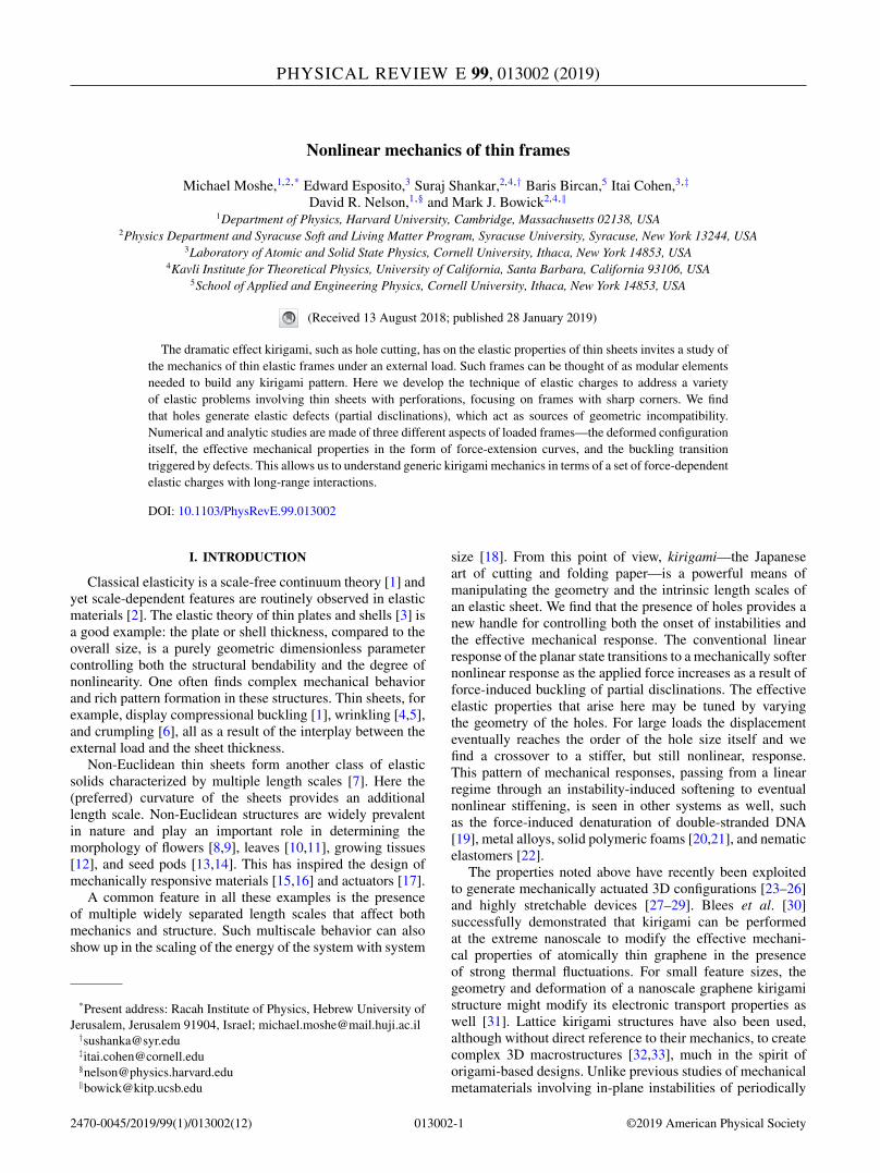
FIG. 1. Kirigami and frames. (a) A periodic kirigami pattern composed of square frames. (b) The response of the pattern in (a) to alarge deformation when stretched along the diagonal x direction, enabled by the escape of the frame elements into the third dimension.(c) An individual square frame of size L, frame width w, and hole dimension H = L − 2w, forming the building block of the pattern in (a).(d)–(f) Different locally stable configurations of a square frame subjected to an external force along its diagonal (in the horizontal direction),distinguished by the relative orientations of the four inner corners: (d) The left and right inner corners are curved up and down, respectively(denoted by + and −, respectively), whereas the top and bottom inner corners point to the left (as shown by the red needles normal to thesurface and denoted by L. This configuration is thus denoted by + : L/L : −). (e) The left and right corners both point up here, while the topand bottom corners point in opposite directions, hence denoted by + : L/R : +. (f) Here both the left and right corners once again point up,but the top and bottom corners point in the same direction, hence + : L/L : +. The remaining configuration + : L/R : − is not stable at thishole size.
perforated thick sheets [34–38], we shall focus primarily onthin elastic sheets that easily buckle into the third dimension,as is most relevant for kirigami. Given the possibilities now af-forded by the design of kirigami metamaterials, an importantquestion remains: What kinds of mechanical properties can beachieved by the techniques of kirigami? In this regard there isprevious work studying the mechanical response of arrays ofslits [24,29,39] and the possibility of topologically protectedfloppy modes in faceted kirigami structures [40], though thefull problem is far from solved.
In search of general principles to organize the mechanicsof kirigami structures, we simplify by dividing the elasticproblem into two simpler problems: the mechanics of a singleframe [as illustrated in Fig. 1(c)], which we view as a modularbuilding block for more complex arrays [Fig. 1(a)], and theinteraction between coupled frames. A detailed analysis ofmany interacting frames will be left to the future. Even thesimple setting of a single frame under load is sufficient touncover a number of general mechanical consequences ofkirigami. In particular, we demonstrate that holes under loadact as sources of geometric incompatibility, which in turndrive buckling. By mapping the mechanics of a pulled frameto that of a non-Euclidean plate, using the formalism of elasticimage charges, we are able to understand both qualitative andquantitative mechanical consequences of modifying the origi-nal geometry. We then show through comparisons with finite-element simulations that this approach to kirigami mechanicsis an improvement on simple linearized plane-elasticity meth-ods. This paper also serves as a theoretical companion to Ref.[41], where we compare our results against experiments onpulled paper frames.
The paper is organized as follows. We start with somesimple tabletop demonstrations in Sec. II to illustrate the qual-itative mechanical features of square frames. Just as electriccharges tend to localize near sharp corners in conventionalelectrostatics, the sharp corners of square frames localizestrain-dependent elastic charges in the form of buckled andunbuckled partial disclinations. In Sec. III we present the the-oretical formalism of image elastic charges within a geometricframework of elasticity. We then discuss the mechanics ofboth planar (Sec. III A) and buckled (Sec. III B) frames. InSec. IV we make a quantitative comparison of our theoreticalpredictions from Sec. III with numerical simulations andelucidate the detailed geometric dependencies in both themechanical force response and the instability threshold.
II. TABLETOP DEMONSTRATIONS
Motivated by the kirigami pattern shown in Fig. 1(a),we choose our prototype frame geometry to be a squaresheet with a centered square hole in it, whose edge length(L), hole size (H ), and frame width [w = (L − H )/2] areshown in Fig. 1(c). Pulling on such a square frame alongdiagonally opposite ends, the first point we note is that theframe readily buckles out of the plane but can adopt multipleconfigurations in doing so. In Figs. 1(d)–1(f) three locallystable configurations of a diagonally loaded square frame areshown, distinguished just by the relative orientations of thebuckled inner corners: Corners with angles less than π/2in the stretched configuration (before buckling) are positivepartial disclinations and can either buckle up or down (±).
013002-2
NONLINEAR MECHANICS OF THIN FRAMES PHYSICAL REVIEW E 99, 013002 (2019)
Corners with angles greater than π/2 in the stretched config-uration before buckling are negative partial disclinations, andthe associated square plaquettes can tilt either to the left orright (L or R). The configurations in Figs. 1(d)–1(f) can thusbe compactly denoted as + : L/L : − (d), + : L/R : + (e),and + : L/L : + (f).
Here we primarily focus only on the global energy-minimizing configuration for a given strain and the associatedenergy landscape of the planar and buckled configurationsfor varying hole sizes and loading conditions. We neglect theeffects of strong thermal fluctuations uncovered in Ref. [30].In principle, for the square frame, there could be 24 = 16 dif-ferent buckled configurations in all, with many related by rota-tions and reflection symmetries. The relative parity of oppos-ing corners (+ versus − and L versus R) completely classifiesthe four distinct buckled configurations, up to symmetry-related degeneracies. However, the configuration + : L/R : −(and its symmetry related cousins) is unstable in the param-eter range we study. The other three locally stable ones areshown in Figs. 1(d)–1(f). We shall only briefly address somefeatures of multistability in pulled frames and defer a moredetailed treatment to future work. As an aside, we do notethat the presence of such multiple local energy minimizers(metastable states) and their associated degeneracies wouldplay an important role when thermal fluctuations are present,and might have nontrivial consequences for, say, the freeenergy of thermalized kirigami microstructures under stress.
There are three main observations that drive our work.First, as demonstrated in Figs. 1(b) and 1(d), the presence ofa hole, or an array of holes, significantly softens the responseof a frame to external forces. Quantifying this softening as afunction of frame width, or equivalently hole size, is an im-portant prerequisite for a thorough understanding of kirigamimechanics. Second, we find that the frame localizes curvaturein the vicinity of the inner corners of a hole, much likethat of a conical surface. Similar singularities and softenedforce-response have been observed previously in the bucklingof other shapes such as slits [24,39]. Third, for small holesizes the frame does not buckle, implying that there is athreshold hole size for buckling (at a fixed displacement).Alternatively, the buckling transition may be triggered byvarying the external diagonal displacement, for a given holegeometry. We shall denote the critical displacement for thebuckling transition in a fixed geometry by δxc. Guided bythese observations, we now proceed to develop a theoreticalframework which naturally captures and emphasizes thesefeatures of frames and kirigami.
III. THEORETICAL FRAMEWORK
The mechanics of an elastic frame is governed by an elasticenergy functional composed of a stretching term depending onthe the 2D Young’s modulus Y and Poisson ratio ν, as well asa bending term proportional to the bending modulus κ . For aHookean material, both the stretching and bending terms arequadratic in the stress (σ ) and extrinsic curvature (b) tensors,respectively. When minimizing the total energy of the system,the equilibrium equations thus obtained can be significantlysimplified by using the Airy stress function χ . The resulting
minimization equations read in covariant form [42]
1
Y��χ = −K, (1a)
κ�tr(b) = σμνbμν. (1b)
Here K is the Gaussian curvature of the configurationadopted by the surface and is proportional to det(b). Note thatthese equilibrium conditions reduce to the standard Föppl-vonKármán (FvK) equations [1] upon geometrically linearizingthe 3D configuration in a Monge patch.
The two elastic moduli together define a characteristiclength scale, commonly interpreted as the effective thicknessof the frame t ≡
√12(1 − ν2)κ/Y , with ν the plate Poisson
ratio, typically within an order of magnitude of the actualthickness of the sheet. In the following we shall use theterm “thickness” to mean effective thickness. The relevantdimensionless parameter that quantifies the ease with whichan elastic sheet can bend rather than stretch is the FvK number(γ ). For a frame, as will be explained below, the appropriatedefinition of γ involves the frame width w as the macroscopiclength scale, which gives γ = Yw2/κ . When γ � 1, theframe typically stretches in-plane, while for γ � 1, it moreeasily trades stretching energy for bending energy and bucklesout of plane instead.
For small displacements, we are in the pre-buckled regime(δx < δxc) and the frame remains planar (b = 0 and K = 0).As discussed below, the buckling threshold δxc is determinedby the FvK number γ . The biharmonic equation for χ alongwith the appropriate boundary conditions (e.g., vanishingnormal stress) completely determines the stressed state of apulled frame. We reinterpret the solution of this problem interms of image charges in the following section.
A. Planar frames
The primary complication in solving the plane stress prob-lem is the presence of a nontrivial hole geometry and thecorresponding boundary conditions that come with it. At thisstage we note that the problem can be solved formally usingthe method of image charges, often used for solving theLaplace equation in the context of classical electromagnetism[43]. In electrostatics, the electric charge density provides asource for the Coulomb potential (via Gauss’s law) whichmakes them dual to each other as generalized conjugatevariables. Equation (1a) tells us that the Airy stress function χ
and the Gaussian curvature are related to each other in a sim-ilar fashion [44]. This identification allows a straightforwardgeneralization of the electrostatic image charge procedure toelastic problems. The basic idea, a kind of variational ansatzfor the frame configuration, is to guess a distribution of image“charges,” now interpreted as sources of Gaussian curvature.This distribution determines the stress function which mustalso satisfy the appropriate boundary conditions on the hole.Equation (1a) is then modified to be
1
Y��χ = KIm − K, (2)
where KIm is the image charge induced within the hole,realized by distributing real elastic charges on its boundary.For the planar case, the Gaussian curvature vanishes (K = 0).
013002-3

MICHAEL MOSHE et al. PHYSICAL REVIEW E 99, 013002 (2019)
The distribution of image charges can then be expanded inmultipoles [45]. A generic hole requires an infinite numberof multipolar terms. Topological constraints, though, requirethat the monopole and dipole terms in KIm, corresponding to aglobal disclination and dislocation, respectively, must vanish[46]. The lowest order allowed multipole in KIm is thereforegenerically the quadrupole [45]. The simple problem of a cir-cular frame under pure external shear can thus be reinterpretedas a combination of fictitious charges at the origin and atinfinity, with a solution which follows from symmetry (seeAppendix A). For a more complicated geometry and boundaryconditions, such as a square hole with sharp corners pulledalong the diagonal, one has to include higher order multipoles,though the quadrupole is often still the dominant contribution[47]. Including all the multipolar image charges is entirelyequivalent to the original elastic problem and sufficient tosatisfy the relevant boundary conditions. Provided the hole isnot too big [47], this formulation characterizes perforations inan elastic sheet under stress as sources of geometric incom-patibility.
Since Eq. (2) is linear in χ for planar frames, we cansuperpose the different multipolar image charges to obtain aKIm that satisfies the appropriate boundary conditions at theedges of the frame. The displacement field �ui and the stresstensor σ i generated by the ith elastic charge λi , is then
uμ =∑
i
λiuμ
i , (3a)
σμν =∑
i
λiσμν
i . (3b)
Note that �ui and σ i are explicit functions of the individualimage charges [48] and different hole geometries only corre-spond to including a different number of terms and differentcharge magnitudes in the above sums. The functions �ui andσ i can be found separately for each multipole as shown inRef. [44]. Here these charges can be thought of as physicallymotivated variational parameters, one for each force or dis-placement applied along the frame diagonal.
The elastic energy in a domain �, including forces at theboundaries, is then
E = 1
2
∫�
Aμνρσ σμνσ ρσ dS −∮
∂�
Tμuμd�. (4)
Here A is the elastic tensor [7], � is the domain of the entireframe, and T is the boundary force. Writing the stress anddisplacement fields in terms of the elastic charges yields
E =∑i,j
Mijλiλj −∑
i
miλi, (5)
with
Mij = 1
2
∫�
Aμνρσ σμν
i σρσ
j dS, (6a)
mi =∮
∂�
Tμuμ
i d�. (6b)
Since all the σ i and �ui are known explicitly, given a specificframe geometry, we can integrate over the domain � andobtain an expression for the matrix M and the vector m.After minimizing the energy with respect to the image charges
λi , simple linear algebra leads to an explicit formula for themagnitude of the ith charges, namely,
λi = 1
2
∑j
M−1ij mj . (7)
For a circular frame (i.e., an annulus) under pure shear, thismethod leads to the known exact result [49], with all thecharges except the quadrupole and hexadecapole vanishing.
The more complex setup of a square frame with twolocalized tensions f acting on diagonal corners gives riseinstead to an induced fictitious quadrupole charge,
Q(f ) = f L
Yφ1(w/L). (8)
Here φ1 is a dimensionless rational function of the geometry,which diverges as w → 0, and vanishes as w/L → 1/2. Thedivergence as w → 0 results from the softness of a verynarrow (square) frame under fixed tension. For the quitedifferent setup of a fixed displacement of the two diagonalends of the frame, the quadrupolar charge becomes
Q(δx) = L2φ2(w/L)δx
L. (9)
In this case the geometric function φ2 remains finite whenw → 0, and vanishes for w/L → 1/2, as expected for an in-tact sheet (w = L/2). An explicit derivation of the geometricfunctions φ1,2 is given in the Supplemental Material [50]. Sim-ilar expressions hold for higher order charges as well. Keepingthe two lowest order image charges already yields an accurateapproximation to the plane stress solution obtained numeri-cally for a wide range of hole sizes (see Fig. 3 and Sec. IV).
Solutions parametrized with just a few image charges be-come more accurate for weak charges; the regime of validityof the approximation depends on the specific protocol of theprescribed deformation. For a given narrow frame (w/L �1/2), the corresponding charge induced by a prescribed forcewill be larger than that induced by a prescribed displace-ment. A small prescribed displacement, for example, resultsin charges that decrease as the frame narrows. We expect(see Appendix A) that for a fixed prescribed force, the purequadrupole approximation is valid for 0.125 � w/L < 0.5(meaning the energy deviates from the exact value by less than5%). Although we find the quadrupole approximation quitehelpful for physical intuition, it will not in general satisfythe exact boundary conditions; for that, one would need toaccount for all possible multipoles or resort (as we do later inSec. IV) to numerical calculations.
Our approach also allows us to compute the deformedshape of a frame under load. By substituting the image chargesfrom Eq. (7) into Eq. (3) we recover the displacement field.In Fig. 2 we use these displacements to plot configurationsof planar square frames of different frame widths subjectedto the same fixed force applied along the diagonal. The colorencodes the stretching energy density. Although the force isconstant, the resulting displacement varies dramatically as wevary the frame width: w/L = 0.25 (a), 0.2 (b), and 0.1 (c) (seeFig. 2).
The analogy with electrostatics provides simple interpre-tations of various features of these image elastic charge aswell. The hole plays a role of a conductor in electrostatics.
013002-4

NONLINEAR MECHANICS OF THIN FRAMES PHYSICAL REVIEW E 99, 013002 (2019)
FIG. 2. The deformation of a square frame constrained to beplanar and subjected to a fixed force f/(YL) = 0.1 along the di-agonal (from the lower left to the upper right) with fixed L = 1 butvarying hole size H = {0.5, 0.6, 0.8}, as calculated by Eq. (7). Theconfigurations are colored by the energy density on a linear scalefrom blue (low) to white (high). Although the force is fixed, foran appropriate choice of the effective thickness, and if allowed toescape into the third dimension, configuration (a) remains planar,(b) is planar at the buckling threshold, and (c) is beyond the criticalforce threshold for buckling. Note that the interior angles of theframes deviate from π/2 with the application of the force.
Just as induced electric charges concentrate at regions of highcurvature on conductors in an external electric field, the elasticcharges induced within a hole in response to an external loadtend to localize at the sharp corners of the hole. In the planarcase this is evident in energy density plots of Fig. 2. In the 3Dcase, as we shall see in the next section, this elastic chargelocalization leads to curvature localization upon buckling,explaining the observations from the tabletop experiments.
Before moving to the buckled case let us estimate themechanical response of the frame. The geometry of the squarehole allows the induced quadrupolar charge to fractionalizeinto four partial disclinations that localize at each corner,alternating in sign. Given this localization, the relevant lengthscale governing the energy of a single partial disclination isthe corner plaquette size ∼w. We therefore estimate the totalenergy as that of four (unbuckled) corner disclinations:
E2D (δx) ≈ 4Ys2
32πw2 − f δx, (10)
where [using Eq. (9)]
s = Q(δx)/H 2 = φ2(w/L)L2
H 2
δx
L≡ �(w/L)
δx
L(11)
is the partial disclination charge. Minimizing the energy withrespect to δx, the effective spring constant f = keffδx of aframe that remains planar is
keff = const × Y
(w
L
)2
�(w/L)2. (12)
We expect that the function �(w/L) is of order unity inthe range w/L � 1/8 where the quadrupole approximation isvalid.
In summary, we have shown in this section that the solutionto the elastic problem of a planar frame can be approximatedusing image elastic charges formed in the interior of the holeto approximately enforce boundary conditions. These imagecharges are a mathematical representation of the real elasticcharges distributed along the boundary of the perforation, asdiscussed in Appendix A. Depending on the hole shape, the
induced elastic charges migrate toward highly curved regions,as suggested by the analogy with electrostatics.
B. Buckled frames
An elastic sheet embedded in a medium may also escapeinto the third dimension. Under load it will first stretch andthen buckle beyond a threshold displacement δxc. Let ustake the case when bending is energetically much easier thanstretching for a given area sheet, (γ � 1). In this regimethe buckled configuration will be approximately stretchless.Generic configurations will be intrinsically curved with spa-tially inhomogeneous Gaussian curvature, particularly on theboundaries and near the corners. Thus, K = 0 in Eq. (2)—seeAppendix B for an illustration of distributed Gaussian cur-vature over a boundary under load. The stress-free boundaryconditions on the hole can once again be satisfied by a collec-tion of image charges, resulting in a nonvanishing KIm as well.Because of Eq. (2), we expect the geometric and elastic chargedistributions along the boundaries to approximately cancelto minimize energy. This requires K = KIm: the Gaussiancurvature of the buckled sheet screens out the sources of stressgenerated by the elastic charges induced on the boundaries.These elastic charges are essentially the same as those for theplanar problem treated above. This screening effect resemblesthat found for the buckling of topological defects in crystallinemembranes (see Ref. [51]).
Since screening charges localize near the inner corners ofthe frame, we expect that each fractionalized partial disclina-tion deforms the sheet on a scale of size w (just as in the planarcase). If w/L � 1/4 the partial disclinations are separated bydistances larger than w and we expect their interactions tobe negligible. In this case, we can estimate the energy of the3D buckled configuration simply as a superposition of conicalenergies at each corner. In addition, if w/L � 1/8, we find(see below) that the solution is well-approximated by a singlequadrupole and we can neglect higher multipole contributions.This allows us to distinguish three main geometric regimes: (i)w/L > 1/4—small hole sizes where the interaction betweenfictitious partial disclinations is important; (ii) 1/8 < w/L <
1/4—intermediate hole sizes where the deformation is well-described by a single fictitious quadrupole and noninteractingpartial disclinations and (iii) w/L < 1/8—large hole sizeswhere higher order multipoles become important.
Small holes have a minor effect on the elastic softeningof a single frame. Very large holes become very flexible tobend both because they have less material and because of theirshape. In the large hole regime, the frame is more akin toa thin elastic ribbon joined at its ends (see Ref. [41]). Theintermediate hole size regime, probably the most accessiblefor exploring kirigami mechanics, will be our main focusbelow.
The energy of the buckled 3D configuration when sub-jected to an external force f is estimated following argumentssimilar to those used in the planar case. Unlike the planarcase, however, the buckled quadrupoles controlling force-extension curves have multiple locally stable configurationscorresponding to various combinations of up-down bucklingof each partial disclination (see Fig. 1). Each of these statesmay have a different energy. The energetic difference between
013002-5
MICHAEL MOSHE et al. PHYSICAL REVIEW E 99, 013002 (2019)
the solutions originates from the interactions between thebuckled partial disclinations, which we neglect to a first ap-proximation in the intermediate hole regime where the partialdisclinations are well separated. Therefore, as in the planarcase, we estimate the total energy as the sum of the conicalbuckling cost localized at each corner [51–53]
EB (δx) = E2D (δxc ) + 4κ ln (w/rc )
× (c1 s + c2 s2 + · · · ) − f (δx − δxc ), (13)
where rc is a microscopic core size regularizing the conicalsingularity, and is expected to scale linearly with the effectiveframe thickness t . Here the first term is the stretching workdone up until buckling. The numerical constants c1, c2 de-pend on the precise mode by which each partial disclinationbuckles. The partial disclination charge s is given as beforeby Eq. (11). Note the logarithmic dependence of the energyon the frame width w, which is typical for conical surfaces,and is a direct consequence of the curvature localization. Weemphasize that the above energy estimate is valid only in thepost-buckled regime (δx � δxc).
Upon minimizing Eq. (13) with respect to δx, we findthe force-displacement relation f (δx). This gives an effectivespring constant keff = df/dδx of the form
keff = const × κ
L2�(w/L)2 ln (w/rc ). (14)
We can estimate the scaling relations associated with thebuckling transition of a frame under load more precisely. Thebuckling transition can be crossed either by varying the holesize for a fixed external force or by increasing the force atfixed frame width. Since the buckling of a frame is controlledby the buckling of partial disclinations, we can take overresults from the buckling of topological disclinations [51]. InRef. [51] it was shown that a single disclination of charge s
in a finite crystalline membrane (of linear size ∼R) bucklesonly when the defect charge exceeds a critical threshold|sc| = γc/γ with γc ≈ 120. Note that γ = YR2/κ → ∞ asR → ∞ which means the threshold vanishes and all topo-logical disclinations buckle in the thermodynamic limit. Inour case, this analysis yields a partial disclination charges = �(w/L)δx/L, which clearly depends on the prescribeddisplacement as well as the frame’s geometry. This geometricdependence of the charge on w/L has no analog in the casestudied in Ref. [51]. After re-expressing the critical displace-ment in terms of the critical charge, we obtain
δxc
L= γ frame
c κB
Yw2�(w/L)= γ frame
c t2
12w2�(w/L), (15)
where by γ framec we denote the numerical value γc correspond-
ing to the buckling of frames.To summarize the predictions of our theoretical analysis,
we find that within the intermediate hole size regime thedeformation of a frame can be accurately described using afictitious quadrupole, whose spatial distribution depends onthe precise shape and geometry of the hole. For a square holethe screening defects are localized near the sharp corners, aphenomenon that is well known in electrostatics and is consis-tent with the tabletop demonstration presented in the Sec. II.This allows an estimation of the effective spring constants as
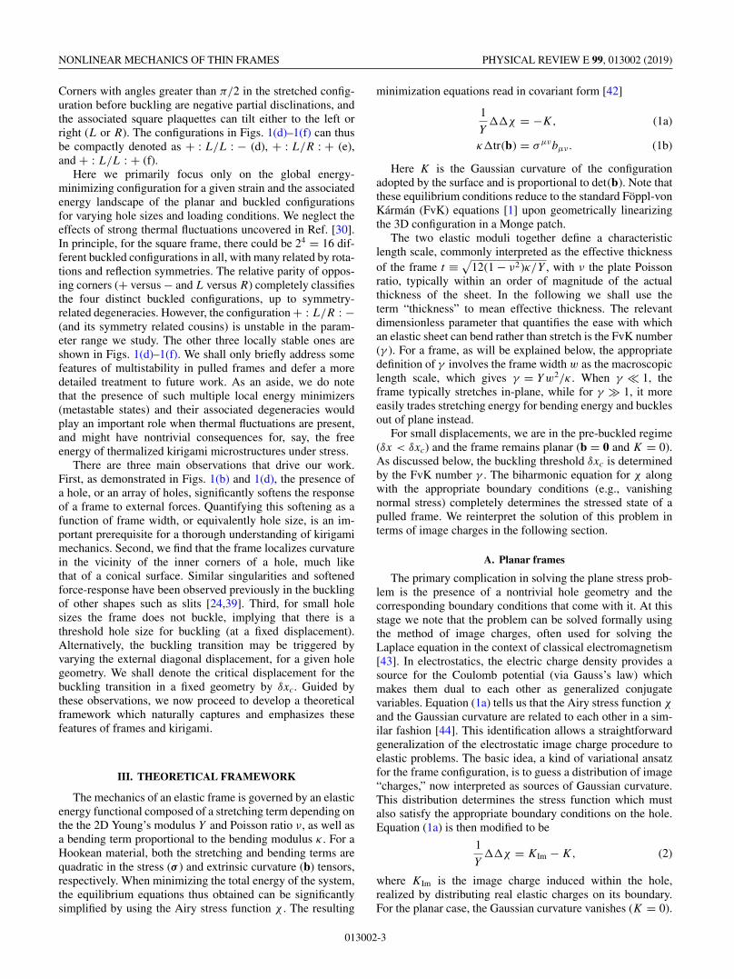
FIG. 3. (a) Planar and (b) buckled energy-minimizing configura-tions obtained by numerical minimization of a frame of side lengthL = 1, width w = 0.45 and prescribed displacement δx/L = 0.05.The frames are colored by their energy density. The scaling of thecolor-bar is chosen to highlight the prominent features of the energydistribution in both configurations. The black dotted lines in (a)are the frame boundaries in the quadrupole-hexadecapole approx-imation described in the text. Note the close agreement betweenthese dotted boundaries and the actual planar configuration computednumerically.
well as a quantitative description of the geometry-dependentscaling of the buckling transition.
IV. NUMERICAL SIMULATIONS
To test the quadrupole and hexadecapole approximationsfor frames of intermediate size, we now analyze the prob-lem numerically. We perform finite element simulations tonumerically minimize a discretized version of the elasticenergy functional (as used, for example, in Refs. [14,54]). Arelated method was used in Ref. [51]. For each frame width atriangulation of the square frame is generated, and the energyis numerically minimized for different material parametersand external displacements.
In Fig. 3(a) we show a representative equilibrium configu-ration of a planar frame under a fixed diagonal displacement.The frame is colored by its elastic energy density, confirmingour expectation of energy localization near the inner corners.The black dotted lines plotted on top of the configuration’sboundaries are the analytical calculations for the deformedframe, using the the two lowest-order multipoles, with thequadrupole and hexadecapole charges as variational param-eters. Note the good agreement. Although we have not suc-ceeded in producing the analog of the quadrupolar approxi-mation for the buckled states, the corresponding disclinationcharges nevertheless provide insight into the buckled state.
In Fig. 3(b) we present the configuration of the same frameas before, only now after allowing buckling. In this case weconfirm that the stretching energy content in the system isindeed negligible compared to the bending energy after buck-ling. Our observations from the tabletop demonstration arealso confirmed—we find clear evidence of energy localizationreflecting the localization of curvature near the inner corners.This feature appears naturally in our analysis as the imageelastic charge fractionalizes in the presence of sharp corners,with partial disclinations localizing at the inner corners ofthe hole. To test this idea further we repeated the simulationfor the buckling of triangular and circular frames, subjectedto the forces shown in Fig. 4. We find that in the triangularcase the induced elastic charges on the boundary are onlypartly fractionalized. One positive disclination monopole is
013002-6

NONLINEAR MECHANICS OF THIN FRAMES PHYSICAL REVIEW E 99, 013002 (2019)
FIG. 4. Three-dimensional energy-minimizing configurations af-ter buckling, obtained by a numerical analysis of the full elasticproblem. (a) Triangular and (b) circular frames subjected to uniaxialforces applied at opposite ends. The screening charges responsiblefor these energy distributions are still of a quadrupolar nature, withthe partial disclinations attracted to the three sharp corners in thetrianglular case, and more smeared out in the annular geometry andalong one side in the case of the triangle.
localized near the corner, whereas the other is smeared onthe opposite side of the triangle [Fig. 4(a) bottom and topsides]. The negative disclination monopoles are also localizedand attracted to the two corners of the triangle’s base. Inthe circular case [Fig. 4(b)] we find that the induced elasticcharges do not fractionalize—they are smeared evenly overthe boundary instead.
In Fig. 5 we plot force-displacement curves on a double-logscale for frames of fixed thickness and four different framewidths. The response is linear for small displacements, sug-gesting that the frame remains planar and responds by stretch-ing controlled by the Young’s modulus Y . A “plateau” withmuch smaller slope then develops, corresponding to buckling.In this regime the Young’s modulus is effectively replacedby κ/L2, as discussed earlier. This is a dramatic softeningfor easily bendable frames. Finally, when the displacementis comparable to the hole size, the response stiffens andstretching becomes important once again. The “noisy” results(especially in the top curve of Fig. 5) are not numerical errors
FIG. 5. Force-displacement curves plotted on a log-log scale forframes with L = 1, t = 0.005. The frame width ranges from topto bottom across w = 0.25, 0.225, 0.175, 0.125. Different modes ofbuckling (see Fig. 1) are responsible for slight qualitative differencesin the buckling pathways, depending on the ratio w/L.
FIG. 6. Log-log force-displacement plots: (a) fixed frame sizew/L = 0.35 and thicknesses t = 0.0005 (green), 0.0011 (blue),0.005 (orange), and 0.05 (cyan), with the force normalized bythe thickness; (b) fixed thickness t = 0.005 and four frame widthsw/L = 0.5, 0.45, 0.35, 0.25, with the force normalized by the w/L-dependence according to Eq. (14).
but rather correspond to locally stable configurations as shownin the inset. The small energetic differences between thesedifferent buckling modes reflects weak interactions betweenthe screening partial disclinations. Although the energeticdifferences are small, we find that for frame sizes w/L �0.175 the + : L/L : − configuration [Fig. 1(d)] is favorable,whereas for wider frames the + : L/L : + configuration isfavorable [Fig. 1(f)].
Force-displacement curves for two different protocols areshown in Fig. 6. In Fig. 6(a) four different thicknesses (orequivalently four different FvK numbers) are shown at fixedframe width. The force is normalized by the thickness andthe data collapses to a single linear curve until the onsetof buckling. Frames with a larger thickness buckle at largervalues of the displacement as expected. Figure 6(b) describesframes with fixed thickness and variable frame width. UsingEq. (12), the force is normalized by w2�(w/L)2 and collapsesto a single curve until the onset of buckling. The nontrivial ge-ometric dependence of the force response is well captured bya single image quadrupolar charge, embodied in the function�(w/L) described by Eq. (11); the post-buckling collapsein Fig. 6(b) strongly suggests that image charges provide anaccurate description even for buckled frames.
The departure of the force response curves from linearity,as in Fig. 6, is a clear but indirect signature of bucklingout of plane. While in experiments this is a useful approachfor estimating the buckling transition, numerical simulationsprovide easy access to the bending energy of frames, whichis a direct measure of the amount of buckling. Figure 7(a)shows a plot of the bending energy normalized by t3 (κ ∼ t3),
FIG. 7. Bending energy as a function of displacement for (a)fixed hole size and different thicknesses, normalized by t3 (whichscales with the bending rigidity κ), and (b) fixed thickness anddifferent hole sizes as in Fig. 6(b), normalized according to Eq. (14).The parameters here are identical to those used in Fig. 6.
013002-7

MICHAEL MOSHE et al. PHYSICAL REVIEW E 99, 013002 (2019)
FIG. 8. Effective spring constant keff = df/dδx as function ofthe dimensionless frame width w for (a) planar and (b) buckledframes with L = 1 and t = 5 × 10⁻⁴. The blue dots are from thenumerical simulations. The solid lines are analytical results corre-sponding to Eq. (12) in (a) with no fitting parameters, and to Eq. (14)in (b) with an overall prefactor as a fitting parameter.
for a fixed frame size and different thicknesses. The collapseto a single curve in the post-buckled regime clearly showsthe dominance of bending there and reflects the significantscreening of the image charge by Gaussian curvature. Thejump in each curve clearly identifies the buckling transition.In Fig. 7(b), the thickness is kept fixed and the frame size isvaried. Now using Eq. (14), we normalize the bending energyby �(w/L)2 ln(w/L), which shows a collapse onto a singlecurve in the post-buckling region.
The analytical approach in the planar problem provided uswith an explicit expression for the effective spring constantfor all values of w/L = (1 − H/L)/2. The assumption ofenergy localization in the vicinity of the inner corners (asappropriate for a square frame) was qualitatively confirmedin Fig. 3 and allows us to estimate the energy of the 3Dconfiguration. To quantitatively test this physical picture, wecompare in Fig. 8(a) the effective spring constant extractedfrom the set of planar frame simulations with the analyticalresult in Eq. (12) estimated by four planar partial disclinationsat each corner. With no fitting parameters we find excellentagreement between the two, for frames with w/L < 1/4 (orequivalently H/L > 1/2), as expected. The exact expressionfor keff = df/dδx for a planar frame and arbitrary framewidth is given in Appendix C.
In Fig. 8(b) we plot the effective spring constant, extractedfrom the simulations in the buckled regime, as a function ofthe normalized frame width w/L, together with the analyticcalculation in Eq. (14). We find good agreement with only oneoverall fitting prefactor. This prefactor reflects the differencebetween the (nontopological) screening disclination and thetopological disclination studied for example in Ref. [51].
Finally, in Fig. 9(a) we plot the critical displacement forbuckling as a function of the thickness on a log-log scale. Thestraight line ∝ t2 superimposed on the numerical data con-firms the scaling prediction given in Eq. (15), with δxc/L ≈75t2. From Eq. (15) we then find that γ frame
c /12w2�(w/L) =75, which, along with w/L = 0.35, gives γ frame
c � 80. This issmaller than the value of γc obtained for the buckling of topo-logical disclinations (γc ≈ 100–120). This difference betweenthe two highlights the distinction between the buckling ofnontopological partial disclinations and of topological ones. Adetailed investigation of such nontopological partial disclina-tion is left for future work. The critical displacement extractedfrom simulations as a function of w/L for a fixed thickness
FIG. 9. Critical displacement for buckling as function of (a) thethickness and (b) the frame width, with solid lines fitted to Eq. (15).The dashed line in (b) goes as w−2, corresponding to the naïveapproximation �(w/L) = constant.
t/L = 0.05 is plotted in Fig. 9(b). Within the “naïve” ap-proach, where the screening disclinations are assumed to beindependent of the frame width [i.e., �(w/L) = const], thecritical displacement is expected to scale like 1/w2, as shownby the blue dashed curve. Taking into account the function�(w/L), as in Eq. (15), we obtain the solid blue line whichagrees well with our numerical results.
V. SUMMARY AND DISCUSSION
In this paper we have applied the geometric formulation ofelasticity to study the mechanics of square frames, especiallytheir buckling into the third dimension. Using the notion ofexternal force or displacement-dependent elastic charges, wedeveloped tools for an explicit and direct computation ofthe stressed state of planar frames given an arbitrary holegeometry. We have shown how stress-induced image chargeswithin the hole can fractionalize into partial disclinationslocalized at sharp corners of the hole. In the buckled regime,frames respond to applied loads by screening these inducedimage charges. The bending energy of elastically distortedframes was then estimated within this formalism. The imagecharge approach made the challenging nonlinear problem ofpost-buckling mechanics accessible by directly relating it to asimpler pre-buckling computation within the planar problem.
The specific simplifications afforded to us by the square ge-ometry of the hole allowed analytical predictions to be quan-titatively tested against numerical simulations. Our findingssupport the analysis both qualitatively and quantitatively. Theanalogy with electrostatics provides an appealing intuitivepicture which allows for the interpretation of the mechanicsof frames through the formation of elastic charges.
It seems plausible that the mechanics of more elaboratekirigami structures under stress could profitably be thought ofas a problem of interacting elastic charges. This perspectivecould provide a powerful organizational framework to thinkabout the mechanics of kirigami metamaterials. In this regard,our work can be seen as the first step toward addressing thegeneral problem. We leave a detailed study of kirigami withmany interacting charges (either screening or fictitious) forfuture investigation.
ACKNOWLEDGMENTS
We thank Paul McEuen for insightful discussions. Work byM.J.B. was supported by the KITP Grant No. PHY-1125915,KITP NSF Grant No. PHY-1748958, and by the NSF DMREF
013002-8
NONLINEAR MECHANICS OF THIN FRAMES PHYSICAL REVIEW E 99, 013002 (2019)
program, via Grant No. DMREF-1435794. Work by I.C. wassupported by a grant from the NSF DMREF program underGrant No. DMR-1435829. Work by D.R.N. was primarilysupported through the NSF DMREF program, via Grant No.DMREF-1435999, as well as in part through the HarvardMaterials Research and Engineering Center, via NSF GrantNo. DMR-1420570. M.M. acknowledges the USIEF Ful-bright program. M.M., S.S., and M.J.B. thank the SyracuseSoft & Living Matter Program for support and the KITP forhospitality during completion of some of this work.
APPENDIX A: IMAGE CHARGE METHODFOR A SHEARED PLANAR ANNULUS
Denote by C(r ) an undeformed circular domain of radiusr . We define the annular domain with outer and inner radiirout and rin by � = C(rout)\C(rin). The width of the annulus isdenoted by δr = rout − rin. The plane-stress problem in an an-nular geometry consists of solving the bi-harmonic equation��χ = 0 (see Eq. (1a)) in �, with boundary conditions
σxy |rout = σyx |rout = σ0, σ xx |rout = σyy |rout = 0,
σ rr |rin = σ θθ |rin = 0, σ rθ |rin = σ θ,r |rin = 0, (A1)
on the outer and inner edges, respectively.The solution for the stress function is given by [49]
χ (r, θ ) = (ar4 + br2 + c + dr−2) sin 2θ, (A2)
with
a = 2r2out − 3r2
in
12(r2
out − r2in
)2 σ0, b = 2r2in − r2
out
4(r2
out − r2in
)2 r2inσ0,
c = − r6in
4(r2
out − r2in
)2 σ0, d = r6inr
2out
12(r2
out − r2in
)2 σ0. (A3)
The equilibrium configuration is plotted in Fig. 10. Instead ofsolving Eq. (1a) in �, the same solution can be obtained bysolving
1
Y��χ = KIm, (A4)
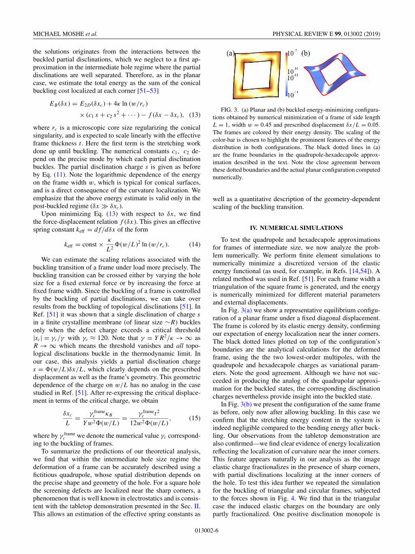
FIG. 10. The analytic solution for an annulus subjected to pureexternal shear on its external boundary.
FIG. 11. The deviation from the exact solution of the approxi-mate energy of a sheared circular frame, obtained by neglecting thehexadecapole. The relative deviation is less than 5% up to a relativehole size of η = rin/rout = 0.7.
in the disk C(rout), where KIm can be nonzero in C(rin) andcorresponds to the image elastic charges required to satisfythe boundary conditions.
The first two terms (a and b) in Eq. (A2) can be viewed asresulting from image charges at infinity. The remaining twoterms (c and d) can be viewed as being induced by a singularsource term at the origin of the form
KIm = 2QIm∂x∂yδ(x) + 2HIm∂x∂y�δ(x),
with the magnitude of the charges given by
QIm = − πr6inσ0
Y(r2
out − r2in
)2 , HIm = − πr6inr
2outσ0
6Y(r2
out − r2in
)2 . (A5)
The two singularities correspond to a fictitious quadrupolarcharge and a fictitious hexadecapolar charge, respectively.
To determine the range of validity of the quadrupoleapproximation, for the case of a prescribed shear force σ0,we calculate the energy Eannulus of a sheared annulus fromEq. (A2). The energy is composed of the boundary terms, thequadrupolar and hexadecapolar terms, and an interaction term.Summing them gives
Eannulus = 12 − 12η2 + 3η4 + 5η6
24(1 − η2)
σ 20
Yπr2
out, (A6)
where η = rin/rout = 1 − (δr/rout) is the relative hole size. Inthe limit δr → rout, which equivalent to η → 0, the domain isa full disk, and this expression recovers the standard result
Edisk = πr2out
2Yσ 2
0 . We now compare the exact solution of thecircular geometry with an approximation obtained by neglect-ing the hexadecapolar term. In Fig. 11 we plot the relativedeviation of the approximate solution from the exact one,as a function of the hole size. We find that the deviation isless then 5% for frame widths of size 0.3 < δr/rout, whichprovides a guide for the pure quadrupole approximation ap-plied to circular frames. Indeed, upon referring to Fig. 1(c),we expect the quadrupole approximation to be adequate when0.3 � w/L.
013002-9
MICHAEL MOSHE et al. PHYSICAL REVIEW E 99, 013002 (2019)
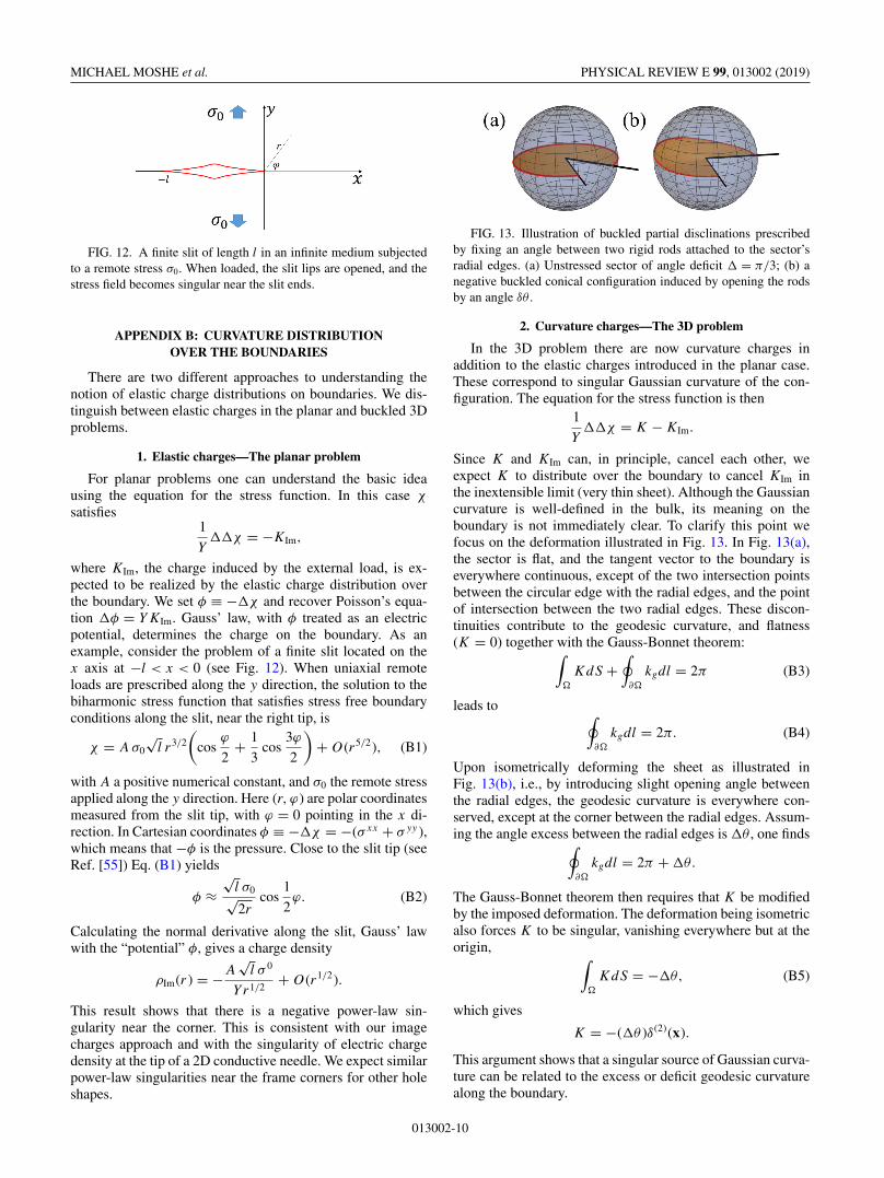
FIG. 12. A finite slit of length l in an infinite medium subjectedto a remote stress σ0. When loaded, the slit lips are opened, and thestress field becomes singular near the slit ends.
APPENDIX B: CURVATURE DISTRIBUTIONOVER THE BOUNDARIES
There are two different approaches to understanding thenotion of elastic charge distributions on boundaries. We dis-tinguish between elastic charges in the planar and buckled 3Dproblems.
1. Elastic charges—The planar problem
For planar problems one can understand the basic ideausing the equation for the stress function. In this case χ
satisfies1
Y��χ = −KIm,
where KIm, the charge induced by the external load, is ex-pected to be realized by the elastic charge distribution overthe boundary. We set φ ≡ −�χ and recover Poisson’s equa-tion �φ = YKIm. Gauss’ law, with φ treated as an electricpotential, determines the charge on the boundary. As anexample, consider the problem of a finite slit located on thex axis at −l < x < 0 (see Fig. 12). When uniaxial remoteloads are prescribed along the y direction, the solution to thebiharmonic stress function that satisfies stress free boundaryconditions along the slit, near the right tip, is
χ = Aσ0
√l r3/2
(cos
ϕ
2+ 1
3cos
3ϕ
2
)+ O(r5/2), (B1)
with A a positive numerical constant, and σ0 the remote stressapplied along the y direction. Here (r, ϕ) are polar coordinatesmeasured from the slit tip, with ϕ = 0 pointing in the x di-rection. In Cartesian coordinates φ ≡ −�χ = −(σxx + σyy ),which means that −φ is the pressure. Close to the slit tip (seeRef. [55]) Eq. (B1) yields
φ ≈√
l σ0√2r
cos1
2ϕ. (B2)
Calculating the normal derivative along the slit, Gauss’ lawwith the “potential” φ, gives a charge density
ρIm(r ) = −A√
l σ 0
Yr1/2+ O(r1/2).
This result shows that there is a negative power-law sin-gularity near the corner. This is consistent with our imagecharges approach and with the singularity of electric chargedensity at the tip of a 2D conductive needle. We expect similarpower-law singularities near the frame corners for other holeshapes.
FIG. 13. Illustration of buckled partial disclinations prescribedby fixing an angle between two rigid rods attached to the sector’sradial edges. (a) Unstressed sector of angle deficit � = π/3; (b) anegative buckled conical configuration induced by opening the rodsby an angle δθ .
2. Curvature charges—The 3D problem
In the 3D problem there are now curvature charges inaddition to the elastic charges introduced in the planar case.These correspond to singular Gaussian curvature of the con-figuration. The equation for the stress function is then
1
Y��χ = K − KIm.
Since K and KIm can, in principle, cancel each other, weexpect K to distribute over the boundary to cancel KIm inthe inextensible limit (very thin sheet). Although the Gaussiancurvature is well-defined in the bulk, its meaning on theboundary is not immediately clear. To clarify this point wefocus on the deformation illustrated in Fig. 13. In Fig. 13(a),the sector is flat, and the tangent vector to the boundary iseverywhere continuous, except of the two intersection pointsbetween the circular edge with the radial edges, and the pointof intersection between the two radial edges. These discon-tinuities contribute to the geodesic curvature, and flatness(K = 0) together with the Gauss-Bonnet theorem:∫
�
KdS +∮
∂�
kgdl = 2π (B3)
leads to ∮∂�
kgdl = 2π. (B4)
Upon isometrically deforming the sheet as illustrated inFig. 13(b), i.e., by introducing slight opening angle betweenthe radial edges, the geodesic curvature is everywhere con-served, except at the corner between the radial edges. Assum-ing the angle excess between the radial edges is �θ , one finds∮
∂�
kgdl = 2π + �θ.
The Gauss-Bonnet theorem then requires that K be modifiedby the imposed deformation. The deformation being isometricalso forces K to be singular, vanishing everywhere but at theorigin, ∫
�
KdS = −�θ, (B5)
which gives
K = −(�θ )δ(2)(x).
This argument shows that a singular source of Gaussian curva-ture can be related to the excess or deficit geodesic curvaturealong the boundary.
013002-10

NONLINEAR MECHANICS OF THIN FRAMES PHYSICAL REVIEW E 99, 013002 (2019)
APPENDIX C: CALCULATION OF keff
In the body of the paper we transformed the problemof a planar frame under load, as expressed in Eq. (4), toa simpler problem as expressed in Eqs. (5) and (7). Thecalculation of the unknown charges requires an integra-tion over the frame of the terms in Eq. (5). The functions
φ1, φ2 and � are expressed in Eqs. (8), (9), and (11)in terms of the energy-minimizing charges. The effec-tive spring constants may then be expressed in terms of�. The calculation for the unknown charges, the func-tions φ1, φ2, �, and the effective spring constants, areall presented in detail in the attached Mathematica note-book.
[1] L. D. Landau and E. M. Lifschitz, The Theory of Elasticity(Pergamon, Oxford, UK, 1986).
[2] B. Audoly and Y. Pomeau, Elasticity and Geometry: From HairCurls to the Nonlinear Response of Shells (Oxford UniversityPress, Oxford, UK, 2010).
[3] W. T. Koiter, Proc. Koninkl. Ned. Akad. van Wetenschappen,Series B 69, 1 (1966).
[4] E. Cerda, K. Ravi-Chandar, and L. Mahadevan, Nature 419, 579(2002).
[5] E. Cerda and L. Mahadevan, Phys. Rev. Lett. 90, 074302(2003).
[6] T. A. Witten, Rev. Mod. Phys. 79, 643 (2007).[7] E. Efrati, E. Sharon, and R. Kupferman, J. Mech. Phys. Solids
57, 762 (2009).[8] H. Liang and L. Mahadevan, Proc. Natl. Acad. Sci. USA 108,
5516 (2011).[9] M. B. Amar, M. M. Müller, and M. Trejo, New J. Phys. 14,
085014 (2012).[10] E. Sharon, M. Marder, and H. L. Swinney, Am. Sci. 92, 254
(2004).[11] H. Liang and L. Mahadevan, Proc. Natl. Acad. Sci. USA 106,
22049 (2009).[12] J. Dervaux and M. Ben Amar, Phys. Rev. Lett. 101, 068101
(2008).[13] S. Armon, E. Efrati, R. Kupferman, and E. Sharon, Science 333,
1726 (2011).[14] S. Armon, H. Aharoni, M. Moshe, and E. Sharon, Soft Matter
10, 2733 (2014).[15] J. Kim, J. A. Hanna, R. C. Hayward, and C. D. Santangelo, Soft
Matter 8, 2375 (2012).[16] Y. Klein, E. Efrati, and E. Sharon, Science 315, 1116 (2007).[17] L. Ionov, Mater. Today 17, 494 (2014).[18] M. Moshe, E. Sharon, and R. Kupferman, Nonlinearity 26, 3247
(2013).[19] S. B. Smith, Y. Cui, and C. Bustamante, Science 271, 795
(1996).[20] K. Y. McCullough, N. A. Fleck, and M. F. Ashby, Acta Mater.
47, 2323 (1999).[21] L. J. Gibson and M. F. Ashby, Proc. Roy. Soc. Lond. A 382, 43
(1982).[22] M. Warner and E. M. Terentjev, Liquid Crystal Elastomers
(Oxford University Press, Oxford, 2003).[23] M. A. Dias, M. P. McCarron, D. Rayneau-Kirkhope, P. Z.
Hanakata, D. K. Campbell, H. S. Park, and D. P. Holmes, Softmatter 13, 9087 (2017).
[24] A. Rafsanjani and K. Bertoldi, Phys. Rev. Lett. 118, 084301(2017).
[25] Y. Zhang, Z. Yan, K. Nan, D. Xiao, Y. Liu, H. Luan, H. Fu, X.Wang, Q. Yang, J. Wang et al., Proc. Natl. Acad. Sci. USA 112,11757 (2015).
[26] A. Lamoureux, K. Lee, M. Shlian, S. R. Forrest, and M. Shtein,Nat. Commun. 6, 8092 (2015).
[27] Z. Song, X. Wang, C. Lv, Y. An, M. Liang, T. Ma, D. He,Y.-J. Zheng, S.-Q. Huang, H. Yu et al., Sci. Rep. 5, 10988(2015).
[28] C. Wu, X. Wang, L. Lin, H. Guo, and Z. L. Wang, ACS Nano10, 4652 (2016).
[29] T. C. Shyu, P. F. Damasceno, P. M. Dodd, A. Lamoureux, L.Xu, M. Shlian, M. Shtein, S. C. Glotzer, and N. A. Kotov,Nat. Mater. 14, 785 (2015).
[30] M. K. Blees, A. W. Barnard, P. A. Rose, S. P. Roberts, K. L.McGill, P. Y. Huang, A. R. Ruyack, J. W. Kevek, B. Kobrin,D. A. Muller et al., Nature 524, 204 (2015).
[31] D. A. Bahamon, Z. Qi, H. S. Park, V. M. Pereira, and D. K.Campbell, Phys. Rev. B 93, 235408 (2016).
[32] D. M. Sussman, Y. Cho, T. Castle, X. Gong, E. Jung, S. Yang,and R. D. Kamien, Proc. Natl. Acad. Sci. USA 112, 7449(2015).
[33] T. Castle, D. M. Sussman, M. Tanis, and R. D. Kamien,Sci. Adv. 2, e1601258 (2016).
[34] B. Florijn, C. Coulais, and M. van Hecke, Phys. Rev. Lett. 113,175503 (2014).
[35] T. Mullin, S. Deschanel, K. Bertoldi, and M. C. Boyce,Phys. Rev. Lett. 99, 084301 (2007).
[36] J. Shim, S. Shan, A. Košmrlj, S. H. Kang, E. R. Chen,J. C. Weaver, and K. Bertoldi, Soft Matter 9, 8198(2013).
[37] E. A. Matsumoto and R. D. Kamien, Phys. Rev. E 80, 021604(2009).
[38] G. Librandi, M. Moshe, Y. Lahini, and K. Bertoldi,arXiv:1709.00328.
[39] M. Isobe and K. Okumura, Sci. Rep. 6, 24758 (2016).[40] Bryan Gin-ge Chen, B. Liu, A. A. Evans, J. Paulose, I. Cohen,
V. Vitelli, and C. D. Santangelo, Phys. Rev. Lett. 116, 135501(2016).
[41] M. Moshe, E. Esposito, S. Shankar, M. J. Bowick, I. Cohen, andD. R. Nelson, Phys. Rev. Lett. 122, 048001 (2019).
[42] J. Chopin, V. Démery, and B. Davidovitch, J. Elasticity 119,137 (2015).
[43] J. D. Jackson, Classical Electrodynamics (John Wiley & Sons,New York, 2007).
[44] M. Moshe, E. Sharon, and R. Kupferman, Phys. Rev. E 92,062403 (2015).
[45] M. Moshe, I. Levin, H. Aharoni, R. Kupferman, andE. Sharon, Proc. Natl. Acad. Sci. USA 112, 10873(2015).
[46] R. Kupferman, M. Moshe, and J. P. Solomon, Arch. Ration.Mech. An. 216, 1009 (2015).
[47] For very thin frames (large holes) higher-order multipole termscan be as important as the leading quadrupolar image charge. A
013002-11

MICHAEL MOSHE et al. PHYSICAL REVIEW E 99, 013002 (2019)
different approach is needed in this ribbon or ring-polymer likelimit (see Ref. [41]).
[48] The stress tensor σ i , and the corresponding strain tensor, gen-erated by each individual charge is linear in the charge λi itselffor a Hookean material. However, the displacement field �ui ingeneral depends nonlinearly on the charge λi due to geometricnonlinearities in the metric tensor. For fixed load applied atthe boundary, the linear charge approximation is only valid forsmall charges. For for fixed external displacement, the mostrelevant case here, the variational problem is exactly linear inthe membrane limit.
[49] J. R. Barber, Elasticity (Springer, Berlin, 1992).
[50] See Supplemental Material at http://link.aps.org/supplemental/10.1103/PhysRevE.99.013002 for the Mathematica notebookused to calculate the results presented here.
[51] H. S. Seung and D. R. Nelson, Phys. Rev. A 38, 1005 (1988).[52] M. M. Müller, M. B. Amar, and J. Guven, Phys. Rev. Lett. 101,
156104 (2008).[53] E. Efrati, L. Pocivavsek, R. Meza, Ka Yee C. Lee, and T. A.
Witten, Phys. Rev. E 91, 022404 (2015).[54] H. Therien-Aubin, M. Moshe, E. Sharon, and E. Kumacheva,
Soft Matter 11, 4600 (2015).[55] C.-T. Sun and Z. Jin, Fracture Mechanics (Elsevier, Amsterdam,
2011).
013002-12


![E99 B80 7547/48 E99 B68 CATALOGO TECNICO1].pdf · Perfiles 10 A30 NEW RPT A30 NEW RPT Varilla tipo "C" de Poliamida de 16 mm Código ET-4689 Aplicación en marcos y hojas ventanas](https://static.fdocuments.net/doc/165x107/5ba879e309d3f256288c85ca/e99-b80-754748-e99-b68-catalogo-1pdf-perfiles-10-a30-new-rpt-a30-new-rpt.jpg)