PHYS202 –SPRING 2009 - physics.udel.edujdshaw/PHYS202/Lecture/Lecture_Notes... · PHYS202...
80
3/1/2009 1 PHYS202 – SPRING 2009 Lecture notes – Magnetism and Electromagnetism
Transcript of PHYS202 –SPRING 2009 - physics.udel.edujdshaw/PHYS202/Lecture/Lecture_Notes... · PHYS202...
3/1/2009
1
PHYS202 – SPRING 2009Lecture notes – Magnetism and
Electromagnetism
3/1/2009
2
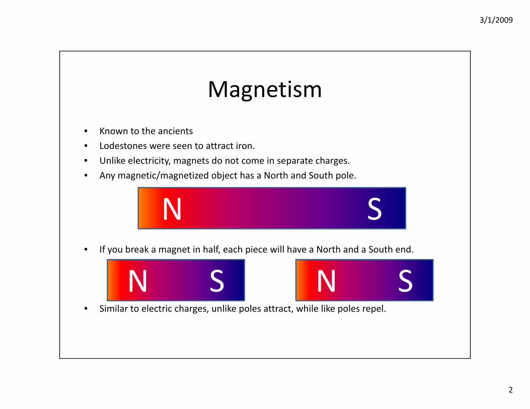
Magnetism
• Known to the ancients
• Lodestones were seen to attract iron.
• Unlike electricity, magnets do not come in separate charges.
• Any magnetic/magnetized object has a North and South pole.
• If you break a magnet in half, each piece will have a North and a South end.
• Similar to electric charges, unlike poles attract, while like poles repel.
N S
N S N S
3/1/2009
3
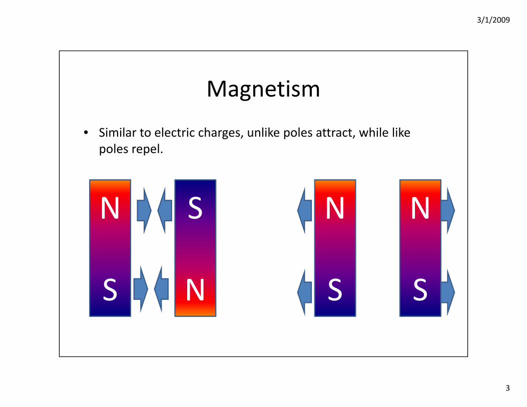
Magnetism
• Similar to electric charges, unlike poles attract, while like poles repel.
N
S
S
N
N
S
N
S
3/1/2009
4
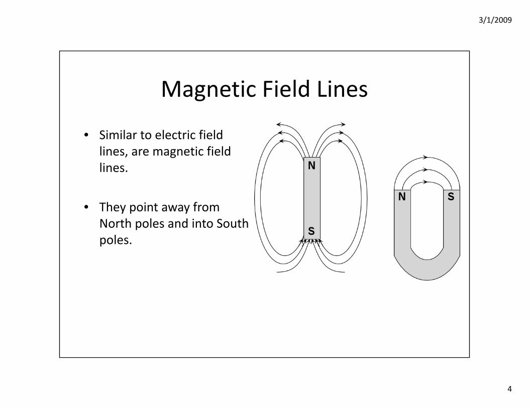
Magnetic Field Lines
• Similar to electric field lines, are magnetic field lines.
• They point away from North poles and into South poles.
3/1/2009
5
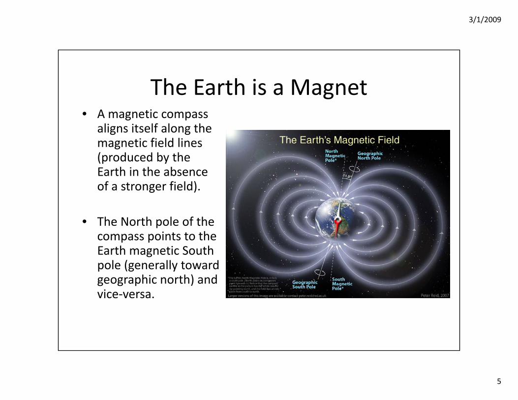
The Earth is a Magnet• A magnetic compass
aligns itself along the magnetic field lines (produced by the Earth in the absence of a stronger field).
• The North pole of the compass points to the Earth magnetic South pole (generally toward geographic north) and vice‐versa.
3/1/2009
6
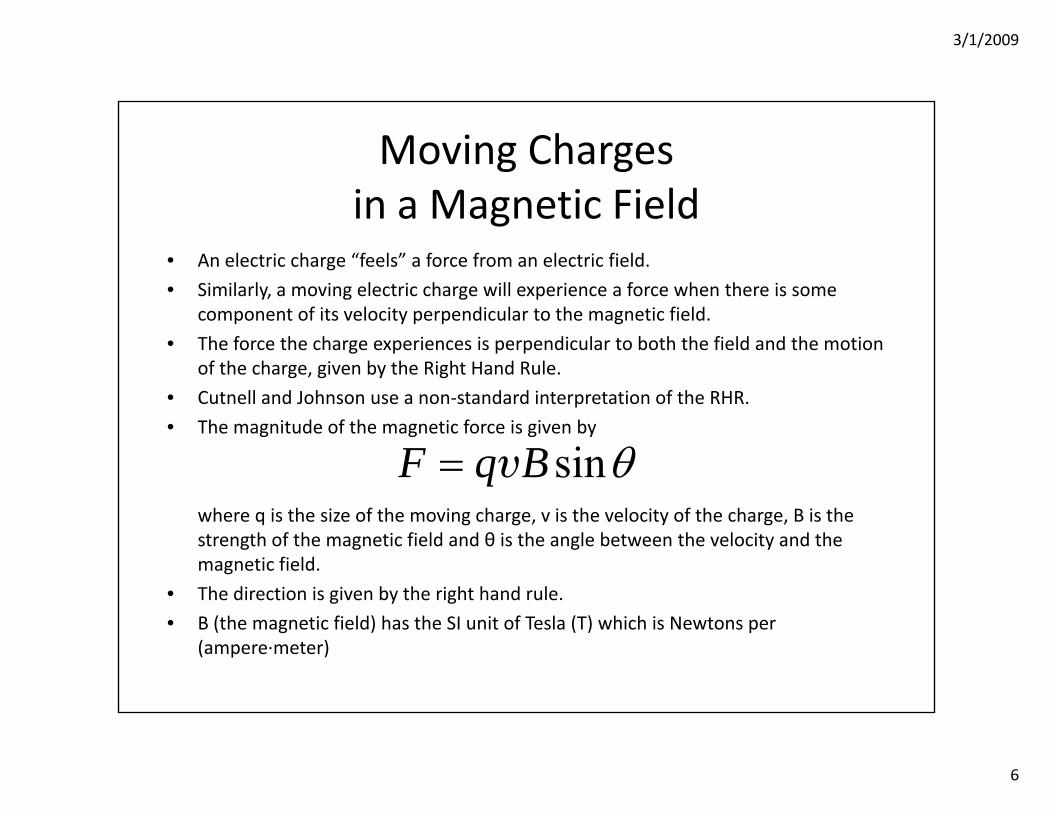
Moving Chargesin a Magnetic Field
• An electric charge “feels” a force from an electric field.
• Similarly, a moving electric charge will experience a force when there is some component of its velocity perpendicular to the magnetic field.
• The force the charge experiences is perpendicular to both the field and the motion of the charge, given by the Right Hand Rule.
• Cutnell and Johnson use a non‐standard interpretation of the RHR.
• The magnitude of the magnetic force is given by
where q is the size of the moving charge, v is the velocity of the charge, B is the strength of the magnetic field and θ is the angle between the velocity and the magnetic field.
• The direction is given by the right hand rule.
• B (the magnetic field) has the SI unit of Tesla (T) which is Newtons per (ampere∙meter)
sinF q B θ= υ
3/1/2009
7
Moving Chargesin a Magnetic Field
• The STANDARD interpretation of the Right Hand Rule.
1. Point the fingers of your right hand in the direction of the velocity of the charge.
2. Curl the ends your fingers in the direction of the magnetic field.
3. Your thumb is now pointed in the direction of the force.
I will use the above. You may use either the above or the book convention.
NOTE: For either interpretation, a negative charge will cause the force to be the opposite direction given by the RHR.

3/1/2009
8
Examples21.4 – When a charged particle moves at an angle of 25° with respect to a magnetic
field, it experiences a magnetic force of magnitude F. At what angle (less than 90°) with respect to this field will this particle, moving at the same speed, experience a magnetic force of magnitude 2F?Use the equation for force on a charged particle in a magnetic field:
Since, q, v, and B are not changing, we must have,
Dividing the equations,
sinF q B θ= υ
1 1 2 2sin sinF q B F q Bθ θ= =υ υ
1 21 1
1
1
2 2
1 1
1
sin sin
2sin sin 25 58
sinsin
F FF
F
q
F
BF q B
θ θ
θ
θθ
−
−
⎡ ⎤⇒ = ⎢ ⎥
⎣ ⎦⎡ ⎤= =⎢⎣
=
⎥⎦
υυ
3/1/2009
9
Examples
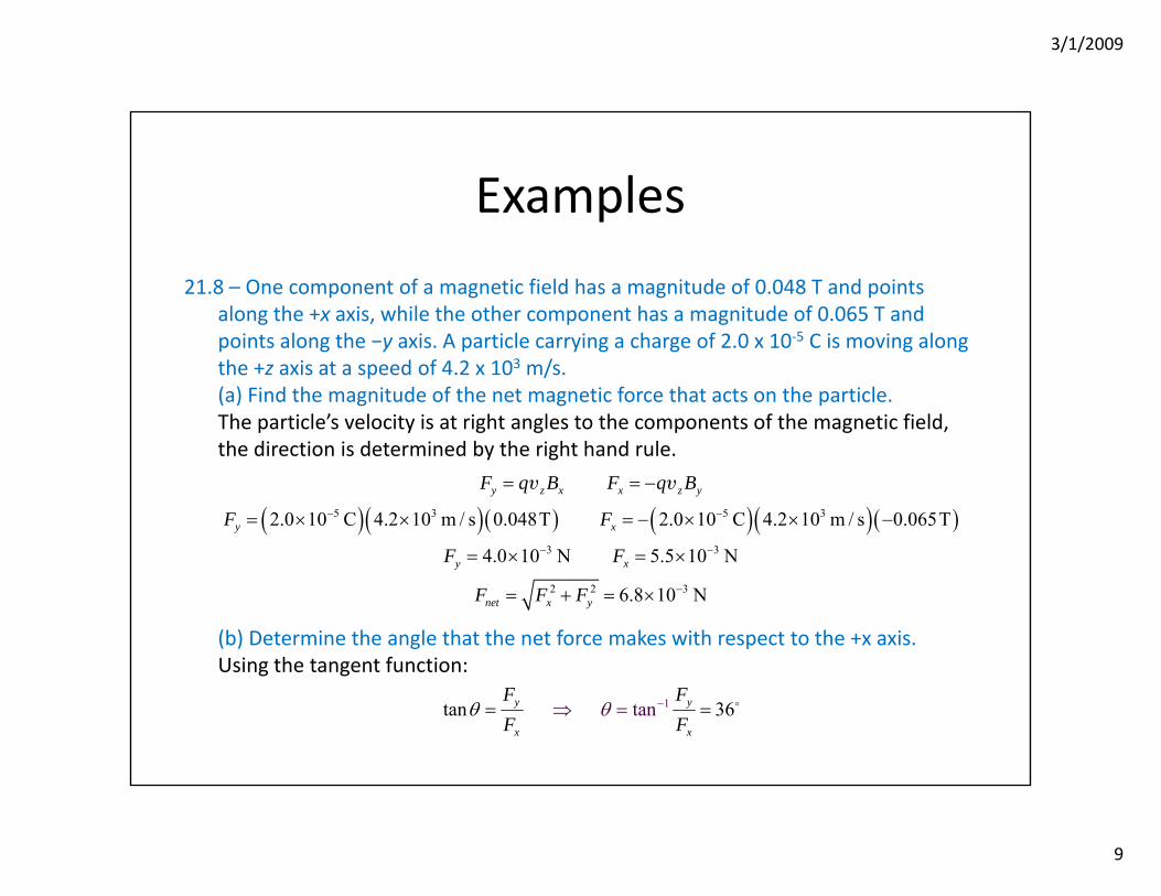
21.8 – One component of a magnetic field has a magnitude of 0.048 T and points along the +x axis, while the other component has a magnitude of 0.065 T and points along the −y axis. A particle carrying a charge of 2.0 x 10‐5 C is moving along the +z axis at a speed of 4.2 x 10³ m/s.(a) Find the magnitude of the net magnetic force that acts on the particle.The particle’s velocity is at right angles to the components of the magnetic field, the direction is determined by the right hand rule.
(b) Determine the angle that the net force makes with respect to the +x axis.Using the tangent function:
( )( )( ) ( )( )( )5 3 5 3
3 3
2 2 3
2.0 10 C 4.2 10 m / s 0.048T 2.0 10 C 4.2 10 m / s 0.065T
4.0 10 N 5.5 10 N
6.8 10 N
y z x x z y
y x
y x
net x y
F q B F q B
F F
F F
F F F
− −
− −
−
= = −
= × × = − × × −
= × = ×
= + = ×
υ υ
1tantan 36y y
x x
F FF F
θ θ −= = =⇒

3/1/2009
10
Examples21.66 – Two charged particles move in the same direction with respect to the same
magnetic field. Particle 1 travels three times faster than particle 2. However, each particle experiences a magnetic force of the same magnitude. Find the ratio |q1|/|q2| of the magnitudes of the charges.Using the equation for magnetic force on a charged particle:
Remembering that v1 = 3v2 and dividing the two equations,
Remembering that v1 = 3v2 F1 = F2,
If the force was the same, not just the magnitude, the signs of the charge would also be the same.
1 1 1 2 2 2sin sinF q B F q Bθ θ= =υ υ
1 11
2 2 2
qFF q
=υ
υ
2 1
2
1
2 2
1 13
⇒ ==3υ
υ
3/1/2009
11
Work, Energyand the Magnetic Field
• The force due to a magnetic field is always at right angles to BOTH the velocity of the charged particle and the magnetic field.
• The work done by any force is the component of the force multiplied by the distance moved in that direction.
• Since at any instant the force is always perpendicular to the motion, there is no component in the direction of motion: Magnetic Fields Do No Work.
• Since no work is performed, the charges kinetic energy cannot change and hence, its speed is constant.
3/1/2009
12
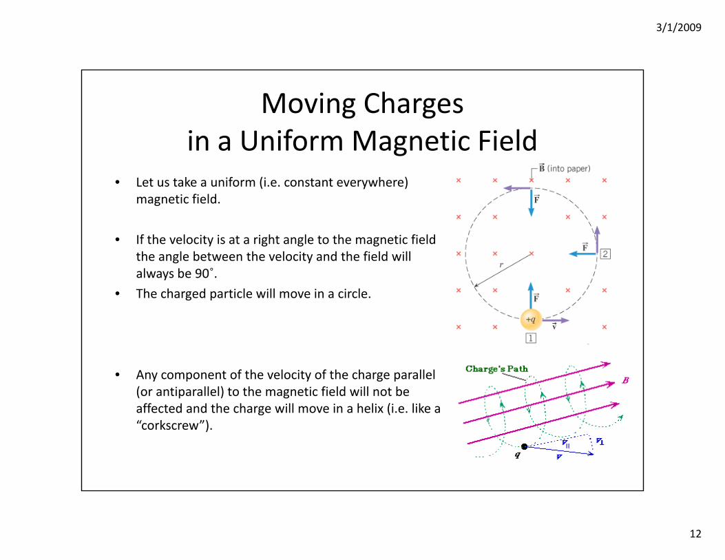
Moving Chargesin a Uniform Magnetic Field
• Let us take a uniform (i.e. constant everywhere) magnetic field.
• If the velocity is at a right angle to the magnetic field the angle between the velocity and the field will always be 90˚.
• The charged particle will move in a circle.
• Any component of the velocity of the charge parallel (or antiparallel) to the magnetic field will not be affected and the charge will move in a helix (i.e. like a “corkscrew”).
3/1/2009
13
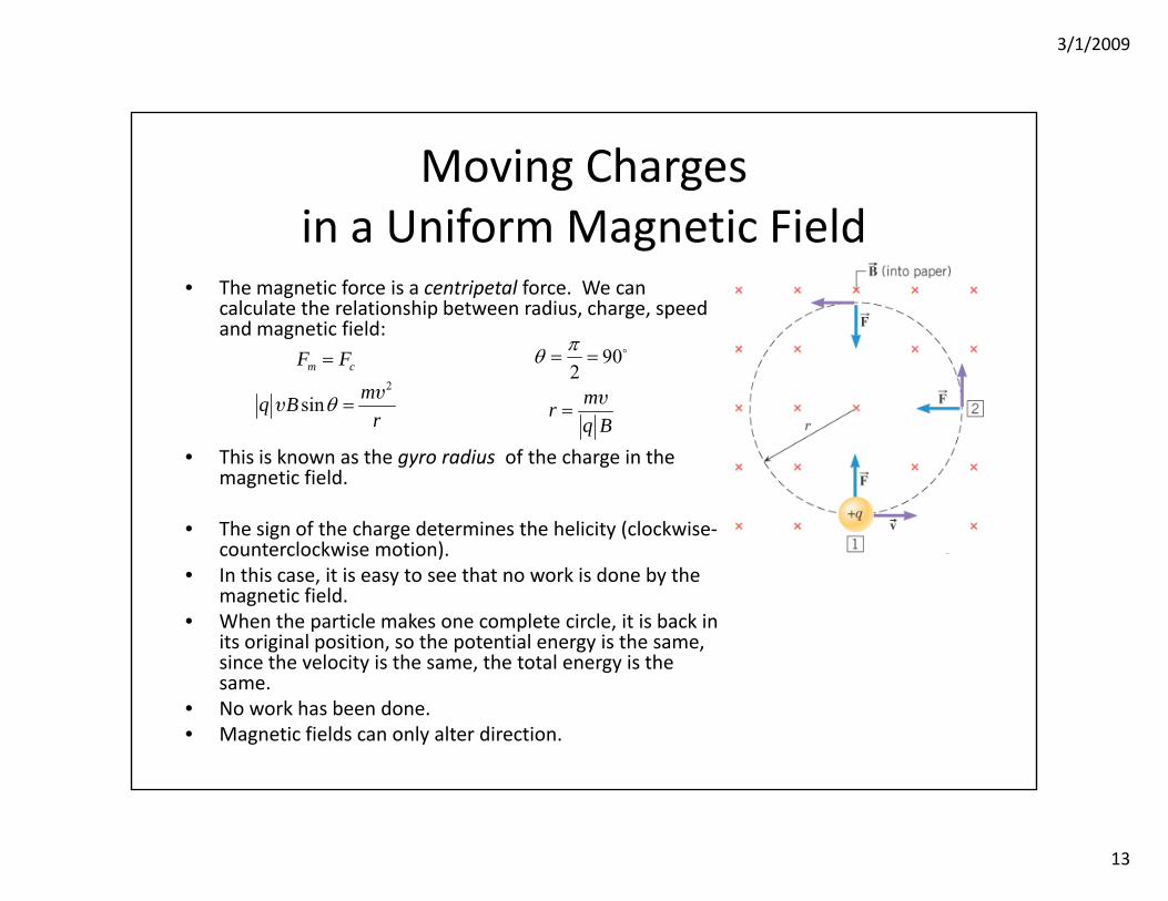
Moving Chargesin a Uniform Magnetic Field
• The magnetic force is a centripetal force. We can calculate the relationship between radius, charge, speed and magnetic field:
• This is known as the gyro radius of the charge in the magnetic field.
• The sign of the charge determines the helicity (clockwise‐counterclockwise motion).
• In this case, it is easy to see that no work is done by the magnetic field.
• When the particle makes one complete circle, it is back in its original position, so the potential energy is the same, since the velocity is the same, the total energy is the same.
• No work has been done.• Magnetic fields can only alter direction.
2
sin
m cF F
mq Br
θ
=
=υ
υ
902
mrq B
πθ = =
=υ
3/1/2009
14
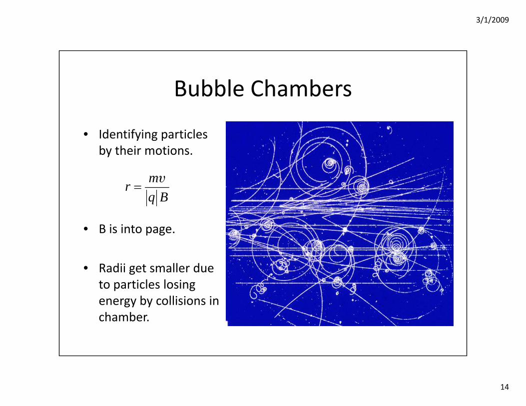
Bubble Chambers
• Identifying particles by their motions.
• B is into page.
• Radii get smaller due to particles losing energy by collisions in chamber.
mrq B
=υ
3/1/2009
15
Examples
21.79 – A proton is projected perpendicularly into a magnetic field with a certain velocity and follows a circular path. Then an electron is projected perpendicularly into the same magnetic field with the same velocity.(a) Does the electron follow the exact same circular path that the proton followed? The electron would follow a path with a smaller radius of curvature with opposite helicity (i.e. counter‐clockwise vs. clockwise or vice‐versa)
(b) To make the electron follow the exact same circular path as the proton, what, if anything, should be done to the direction and the magnitude of the magnetic field? Account for your answer.The magnetic field direction would need to be reversed (accounting for the sign change in the charge) and the field strength reduced by me/mp.

3/1/2009
16
Examples
21.79 – (cont.) A proton is projected perpendicularly into a magnetic field that has a magnitude of 0.50 T. The field is then adjusted so that an electron will follow the exact same circular path when it is projected perpendicularly into the field with the same velocity that the proton had. What is the magnitude of the field used for the electron?
The radius of curvature of a particle is given by . Thus,
The magnetic field is ‐2.7 x 10‐4 T (the negative sign indicates the field is reversed).
mrq B
=υ
( )
( )
( )31
27
9.11 10 kg1.67 10
0.50Tkg
p e
p e
p e e
p ee
e
ppB
m mr reB e B
m m meB e B
Bm
B−
−
⎛ ⎞⇒ = − ⎜
= =−
= ⎟⎜ ⎟⎝ ⎠
⎛ ⎞=
−
××
− ⎜ ⎟⎝ ⎠
υ υ
υ υ
3/1/2009
17
Examples
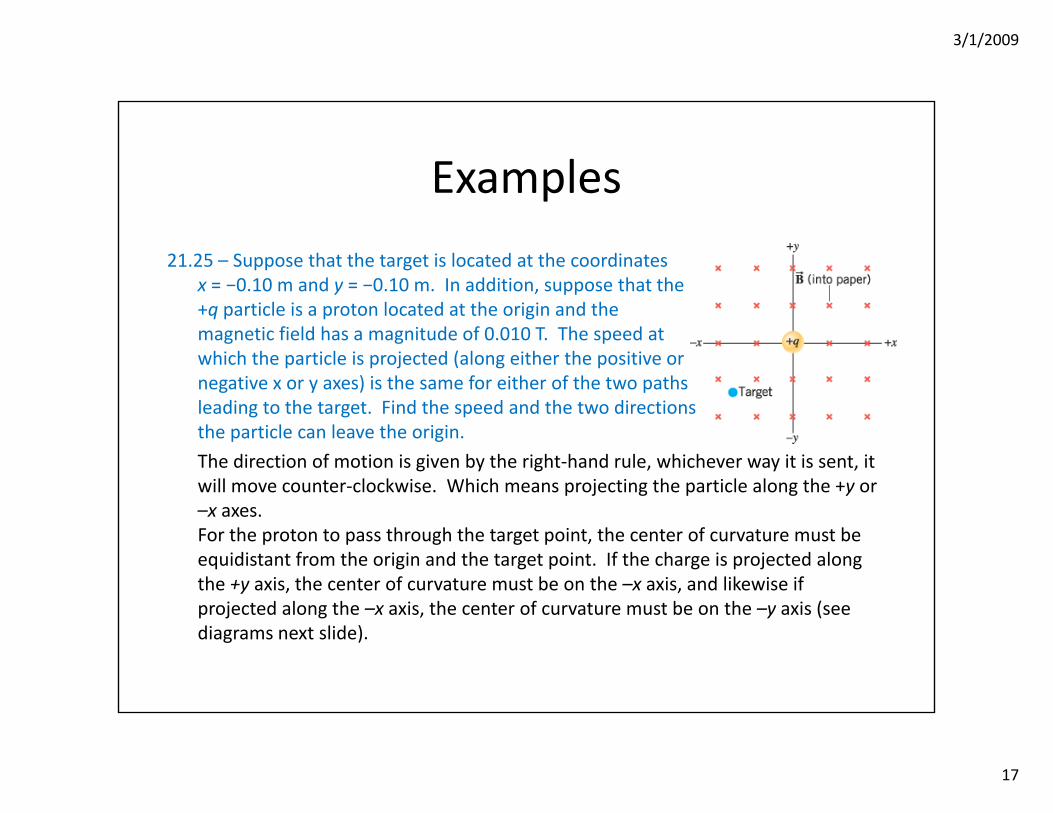
21.25 – Suppose that the target is located at the coordinatesx = −0.10 m and y = −0.10 m. In addition, suppose that the+q particle is a proton located at the origin and themagnetic field has a magnitude of 0.010 T. The speed atwhich the particle is projected (along either the positive or negative x or y axes) is the same for either of the two pathsleading to the target. Find the speed and the two directionsthe particle can leave the origin.
The direction of motion is given by the right‐hand rule, whichever way it is sent, it will move counter‐clockwise. Which means projecting the particle along the +y or –x axes.For the proton to pass through the target point, the center of curvature must be equidistant from the origin and the target point. If the charge is projected along the +y axis, the center of curvature must be on the –x axis, and likewise if projected along the –x axis, the center of curvature must be on the –y axis (see diagrams next slide).
3/1/2009
18
Examples
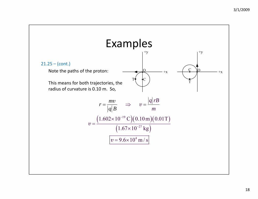
21.25 – (cont.)
Note the paths of the proton:
This means for both trajectories, theradius of curvature is 0.10 m. So,
O O
T
C
+y
+x
T C
+y
+x
( )( )( )( )
19
27
4
1.602 10 C 0.10 m 0.01T
1.67 10 kg
9.6 10 m / s
q rBm
mrq B
−
−
⇒ =
×=
×
= ×
=υ
υ
υ
υ

3/1/2009
19
The Mass Spectrometer
• Using our knowledge of how particles move in a uniform magnetic field:
• We can uniquely determine the radius of a particles trajectory dependent on its speed, mass and charge.
• Typically an ion source strips an atom of one electron, thus leaving a net positive charge of e.
mrq B
=υ
IonSource
3/1/2009
20
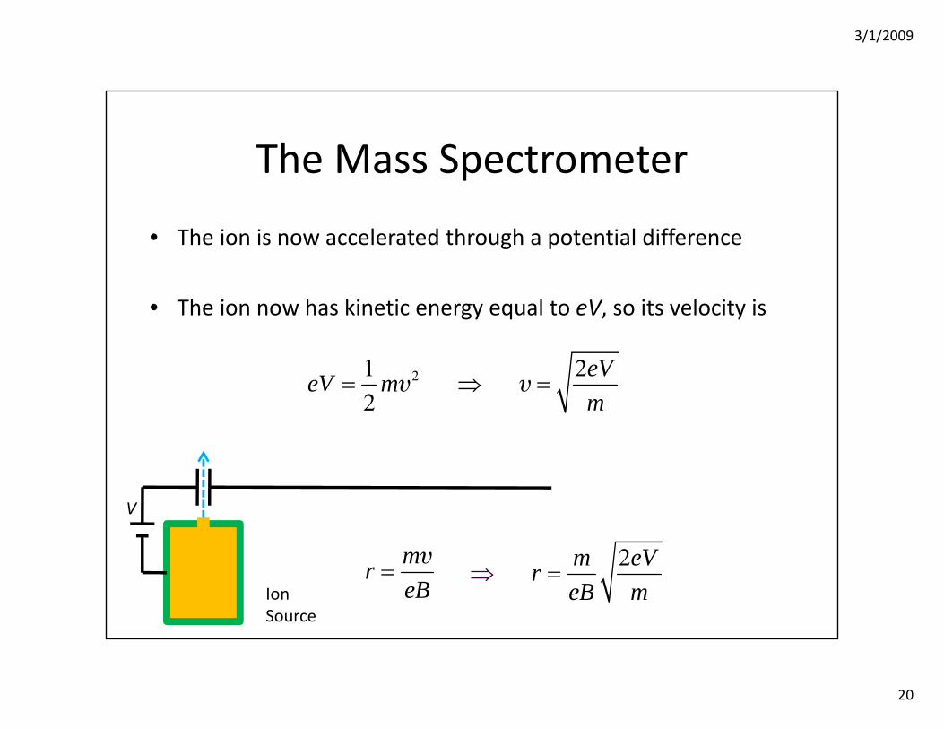
2m eVreB m
⇒ =
The Mass Spectrometer
• The ion is now accelerated through a potential difference
• The ion now has kinetic energy equal to eV, so its velocity is
mreB
=υ
IonSource
V
21 22
eVeV mm
= ⇒ =υ υ
3/1/2009
21
Bin
22
2mVreB
=
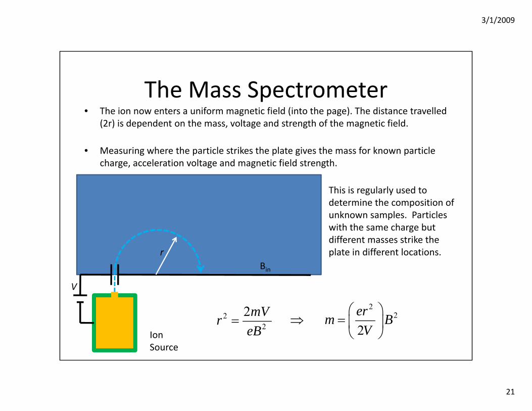
The Mass Spectrometer• The ion now enters a uniform magnetic field (into the page). The distance travelled
(2r) is dependent on the mass, voltage and strength of the magnetic field.
• Measuring where the particle strikes the plate gives the mass for known particle charge, acceleration voltage and magnetic field strength.
IonSource
V
r
22
2erm BV
⎛ ⎞⇒ = ⎜ ⎟
⎝ ⎠
This is regularly used to determine the composition of unknown samples. Particles with the same charge but different masses strike the plate in different locations.
3/1/2009
22
Example
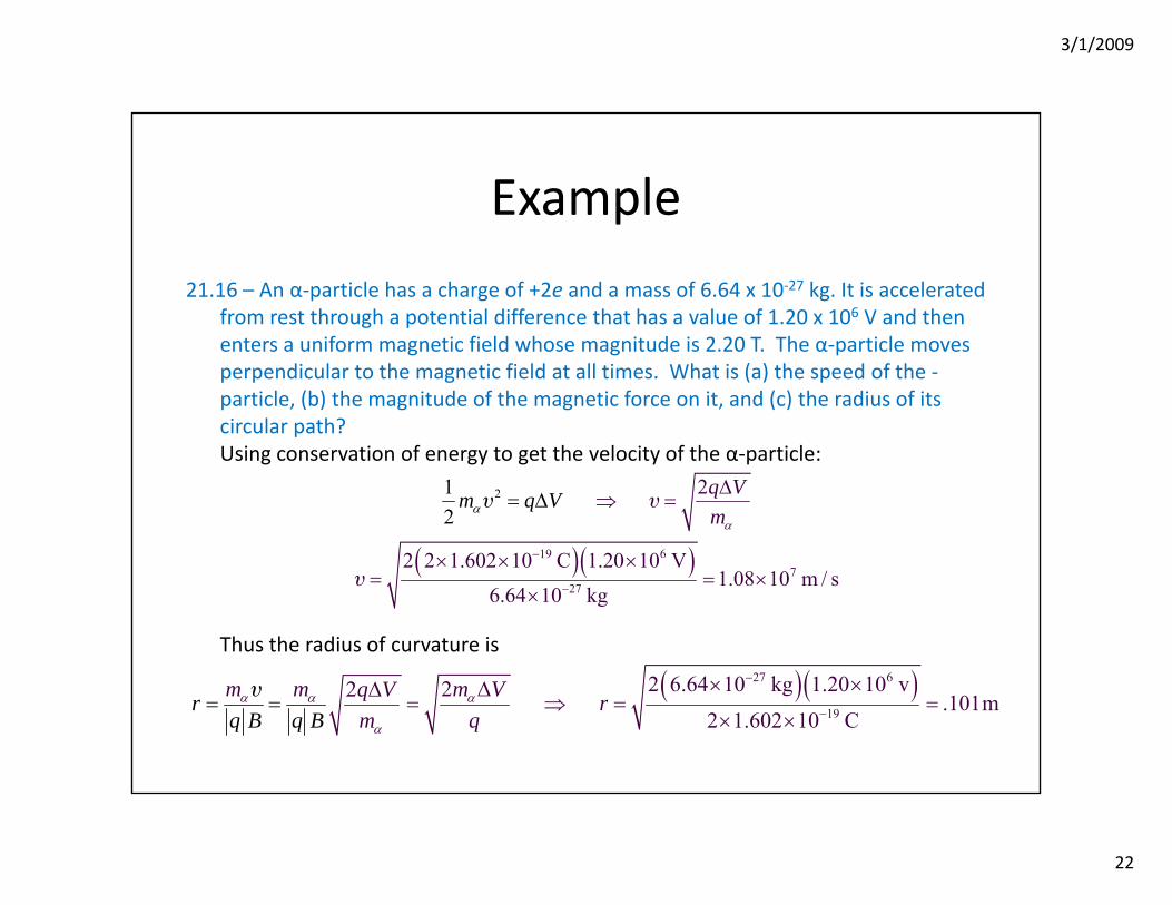
21.16 – An α‐particle has a charge of +2e and a mass of 6.64 x 10‐27 kg. It is accelerated from rest through a potential difference that has a value of 1.20 x 10⁶ V and then enters a uniform magnetic field whose magnitude is 2.20 T. The α‐particle moves perpendicular to the magnetic field at all times. What is (a) the speed of the ‐particle, (b) the magnitude of the magnetic force on it, and (c) the radius of its circular path?Using conservation of energy to get the velocity of the α‐particle:
Thus the radius of curvature is
( )( )27 6
19
2 6.64 10 kg 1.20 10 v22 .101m2 1.602 10 C
m m m Vq V rm
rq B q B qα α α
α
−
−
× ×ΔΔ= ⇒ = =
× ×= =
υ
( )( )19 67
7
2
2
2
2 2 1.602 10 C 1.20 10 V1.08 10 m / s
6.64 1 g
12
0 k
m q q Vm
Vαα
−
−
Δ⇒ =
× × ×= = ×
Δ
×
= υυ
υ

3/1/2009
23
Force on Current Carrying Wires
• In some time (Δt), an amount of charge (Δq) moves through the section of wire.
• Let us multiply by one: (Δt/ Δt),
• This is simply the current and the length of the wire.
• The force is
( ) sinF q B θ= Δ υ
IV+
V–
L
( ) sinqF t Bt
θΔ⎛ ⎞= Δ⎜ ⎟Δ⎝ ⎠υ
sinF ILB θ=
3/1/2009
24
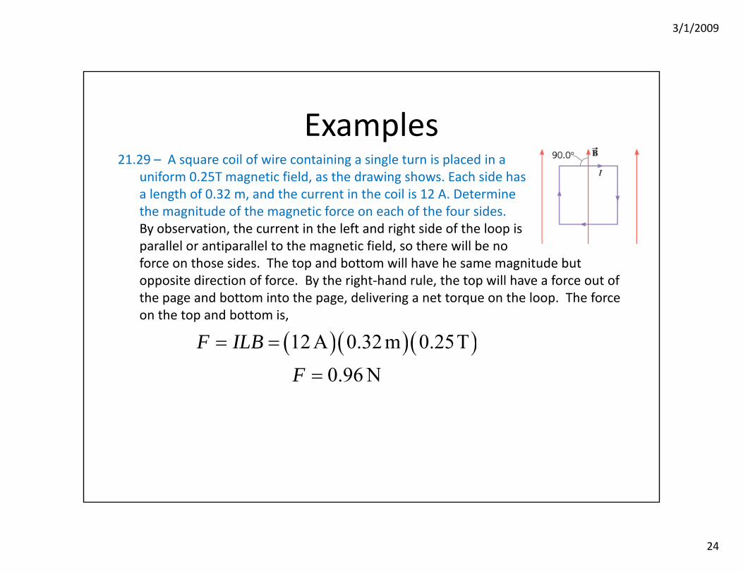
Examples21.29 – A square coil of wire containing a single turn is placed in a
uniform 0.25T magnetic field, as the drawing shows. Each side hasa length of 0.32 m, and the current in the coil is 12 A. Determinethe magnitude of the magnetic force on each of the four sides.By observation, the current in the left and right side of the loop isparallel or antiparallel to the magnetic field, so there will be no force on those sides. The top and bottom will have he same magnitude but opposite direction of force. By the right‐hand rule, the top will have a force out of the page and bottom into the page, delivering a net torque on the loop. The force on the top and bottom is,
( )( )( )12 A 0.32 m 0.25T0.96 N
F ILBF
= =
=
3/1/2009
25
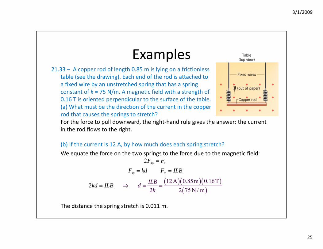
Examples21.33 – A copper rod of length 0.85 m is lying on a frictionless
table (see the drawing). Each end of the rod is attached toa fixed wire by an unstretched spring that has a springconstant of k = 75 N/m. A magnetic field with a strength of0.16 T is oriented perpendicular to the surface of the table.(a) What must be the direction of the current in the copperrod that causes the springs to stretch?For the force to pull downward, the right‐hand rule gives the answer: the current in the rod flows to the right.
(b) If the current is 12 A, by how much does each spring stretch?
We equate the force on the two springs to the force due to the magnetic field:
The distance the spring stretch is 0.011 m.
( )( )( )( )
12 A 0.85m 0.16T2 2 75 N / m
2
2
sp m
sp m
ILBd
F F
F kd F ILB
kd ILBk
=
= =
⇒ = ==

3/1/2009
26
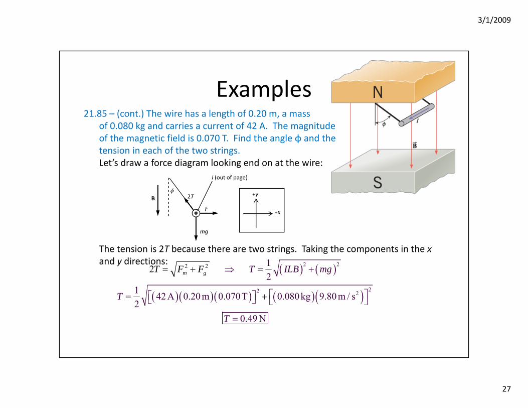
Examples21.85 – A horizontal wire is hung from the ceiling of a
room by two massless strings. A uniform magnetic fieldis directed from the ceiling to the floor. When a currentexists in the wire, the wire swings upward and makesan angle φ with respect to the vertical, as the drawingshows.(a) How is the magnitude of the magnetic force relatedto the magnetic field, the length of the wire, and the current in the wire?
(b) What is the direction of the magnetic force? By the RHR it is to the right.
(c) The wire is stationary, so it is in equilibrium. What are the forces that keep it in equilibrium?Gravitational force on the wire and the magnetic force due to the current and magnetic field interaction.
(d) What must be true about the sum of the forces in the horizontal direction and the sum of the forces in the vertical direction?If there is no motion, then the sum of the forces must be zero in both directions.
F ILB=
3/1/2009
27
Examples21.85 – (cont.) The wire has a length of 0.20 m, a mass
of 0.080 kg and carries a current of 42 A. The magnitudeof the magnetic field is 0.070 T. Find the angle φ and thetension in each of the two strings.Let’s draw a force diagram looking end on at the wire:
The tension is 2T because there are two strings. Taking the components in the xand y directions:
φB
mg
F
2T
+x
+y
I (out of page)
( ) ( )
( )( )( ) ( )( )
2 2 2
2
2
22
12
1 42 A 0.20 m 0.070T 0.080 kg 9.80 m / s2
0.49
2
N
m g T ILT mg
T
F BF
T
⇒ = +
⎡ ⎤⎡ ⎤= +⎣ ⎦ ⎣ ⎦
=
= +
3/1/2009
28
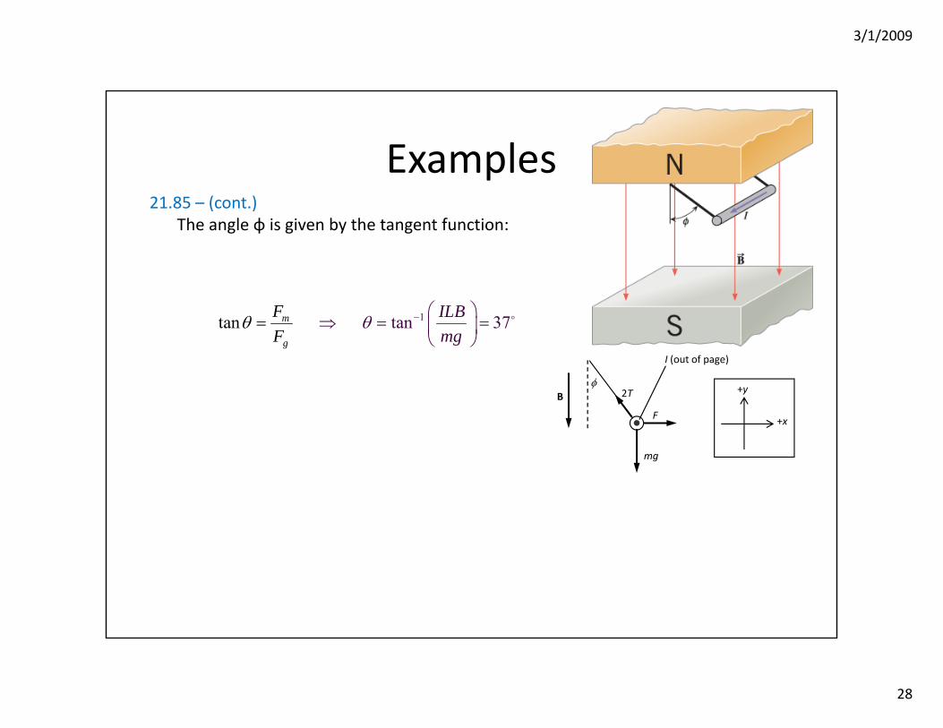
Examples21.85 – (cont.)
The angle φ is given by the tangent function:
φB
mg
F
2T
+x
+y
I (out of page)
1t n 37n ta am
g
IFF
LBmg
θ θ − ⎛ ⎞⇒ = =⎜ ⎟
⎠=
⎝
3/1/2009
29
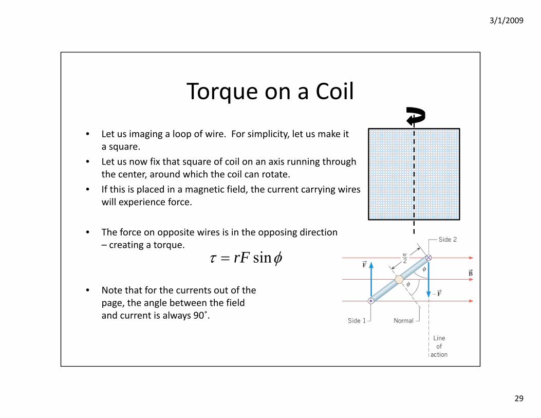
Torque on a Coil
• Let us imaging a loop of wire. For simplicity, let us make ita square.
• Let us now fix that square of coil on an axis running throughthe center, around which the coil can rotate.
• If this is placed in a magnetic field, the current carrying wireswill experience force.
• The force on opposite wires is in the opposing direction– creating a torque.
• Note that for the currents out of thepage, the angle between the fieldand current is always 90˚.
sinrFτ φ=
3/1/2009
30
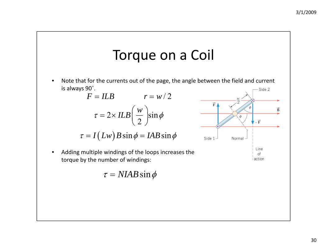
Torque on a Coil
• Note that for the currents out of the page, the angle between the field and current is always 90˚.
• Adding multiple windings of the loops increases thetorque by the number of windings:
/ 2
2 sin2
F ILB r wwILBτ φ
= =
⎛ ⎞= × ⎜ ⎟⎝ ⎠
( ) sin sinI Lw B IABτ φ φ= =
sinNIABτ φ=
3/1/2009
31
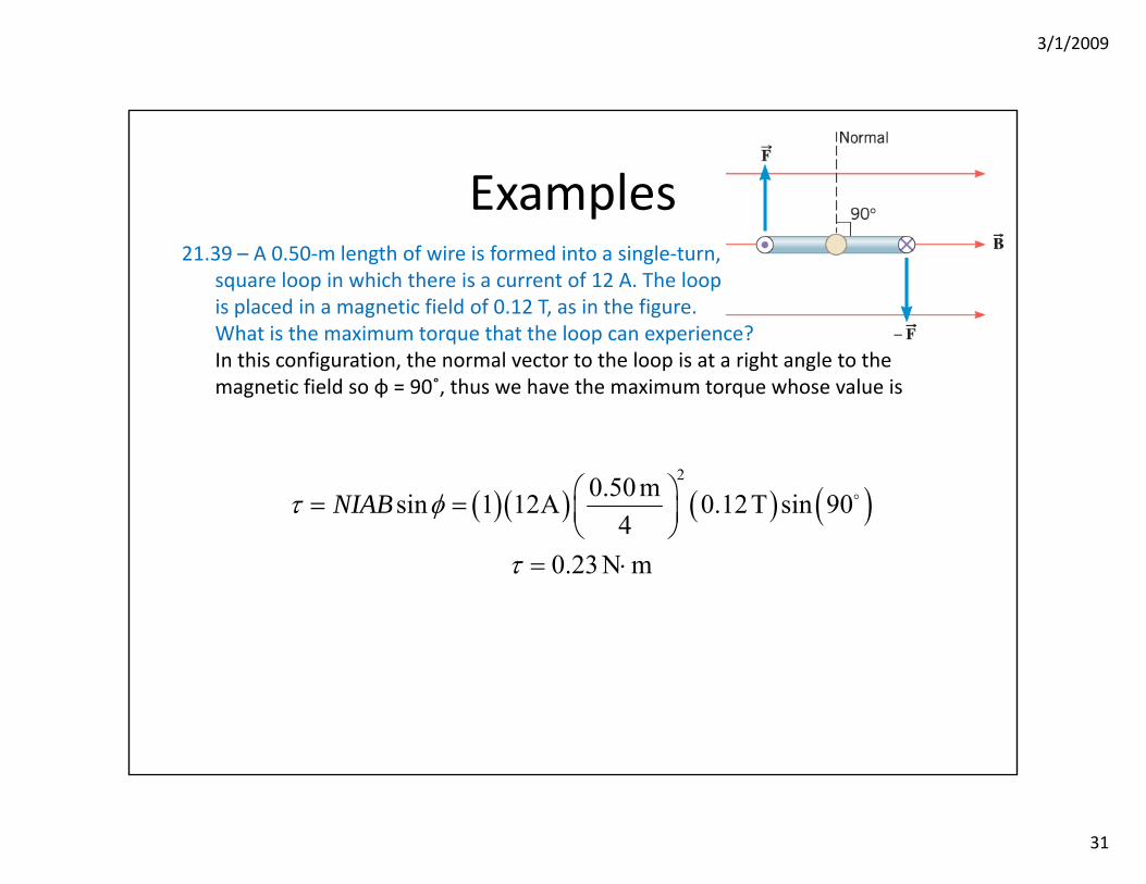
Examples21.39 – A 0.50‐m length of wire is formed into a single‐turn,
square loop in which there is a current of 12 A. The loopis placed in a magnetic field of 0.12 T, as in the figure.What is the maximum torque that the loop can experience?In this configuration, the normal vector to the loop is at a right angle to the magnetic field so φ = 90˚, thus we have the maximum torque whose value is
( )( ) ( ) ( )20.50 msin 1 12 0.12T sin 90
40.23 N m
NIABτ φ
τ
⎛ ⎞= = Α ⎜ ⎟⎝ ⎠
= ⋅
3/1/2009
32
Examples
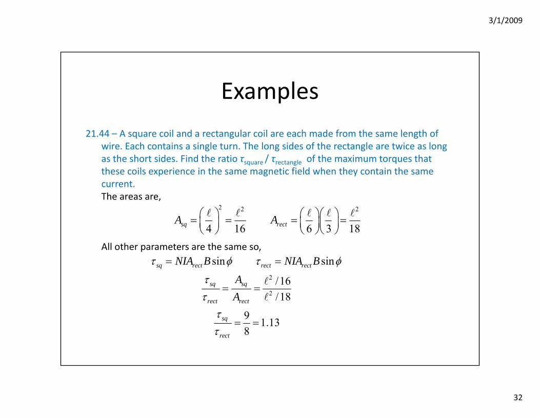
21.44 – A square coil and a rectangular coil are each made from the same length of wire. Each contains a single turn. The long sides of the rectangle are twice as long as the short sides. Find the ratio τsquare / τrectangle of the maximum torques that these coils experience in the same magnetic field when they contain the same current. The areas are,
All other parameters are the same so,
2 2 2
4 16 6 3 18sq rectA A⎛ ⎞ ⎛ ⎞⎛ ⎞= = = =⎜ ⎟ ⎜ ⎟⎜ ⎟⎝ ⎠ ⎝ ⎠⎝ ⎠
2
2
sin sin
/16/18
9 1.138
sq rect rect rect
sq sq
rect rect
sq
rect
NIA B NIA B
AA
τ φ τ φ
ττ
ττ
= =
= =
= =
3/1/2009
33
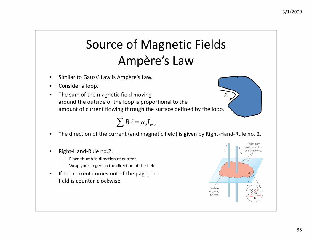
Source of Magnetic FieldsAmpère’s Law
• Similar to Gauss’ Law is Ampère’s Law.
• Consider a loop.
• The sum of the magnetic field moving around the outside of the loop is proportional to theamount of current flowing through the surface defined by the loop.
• The direction of the current (and magnetic field) is given by Right‐Hand‐Rule no. 2.
• Right‐Hand‐Rule no.2:– Place thumb in direction of current.
– Wrap your fingers in the direction of the field.
• If the current comes out of the page, thefield is counter‐clockwise.
0 encB Iμ=∑
3/1/2009
34
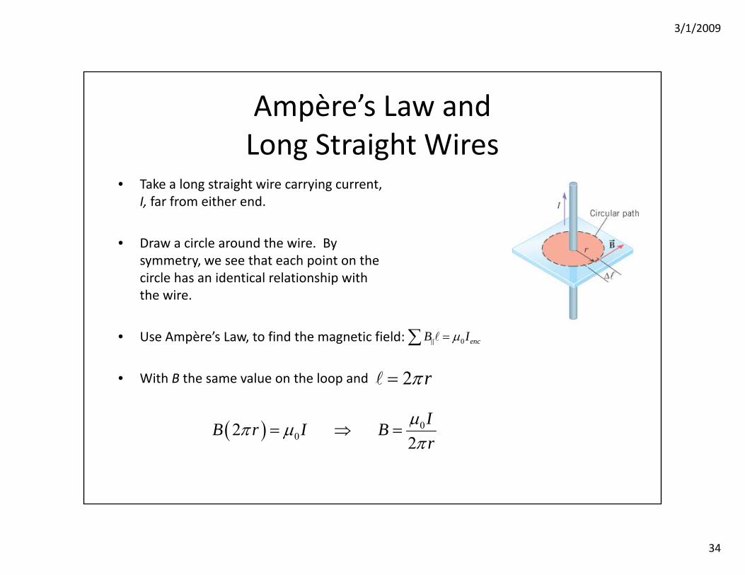
Ampère’s Law andLong Straight Wires
• Take a long straight wire carrying current, I, far from either end.
• Draw a circle around the wire. Bysymmetry, we see that each point on thecircle has an identical relationship withthe wire.
• Use Ampère’s Law, to find the magnetic field:
• With B the same value on the loop and
0 encB Iμ=∑
2 rπ=
( ) 002
2IB r I Br
μπ μπ
= ⇒ =
3/1/2009
35
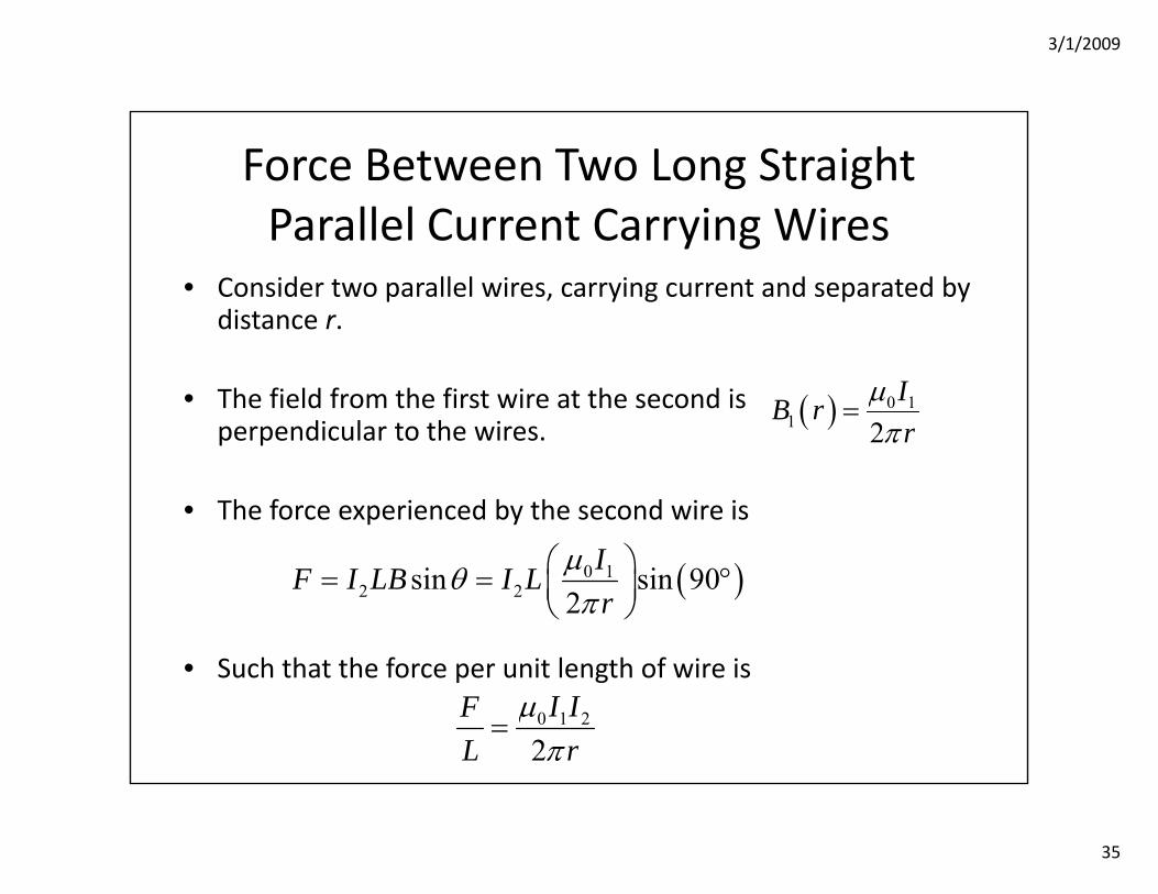
Force Between Two Long Straight Parallel Current Carrying Wires
• Consider two parallel wires, carrying current and separated by distance r.
• The field from the first wire at the second isperpendicular to the wires.
• The force experienced by the second wire is
• Such that the force per unit length of wire is
( ) 0 11 2
IB rr
μπ
=
( )0 12 2sin sin 90
2IF I LB I Lr
μθπ
⎛ ⎞= = °⎜ ⎟⎝ ⎠
0 1 2
2I IF
L rμπ
=
3/1/2009
36
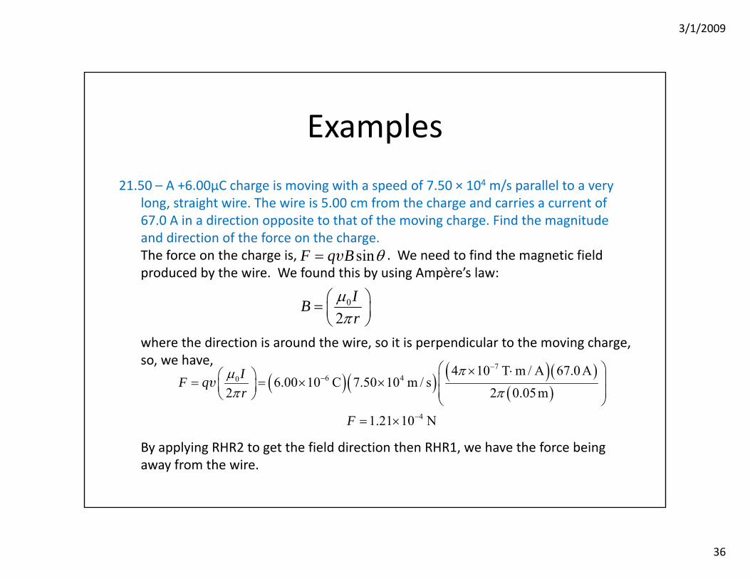
Examples
21.50 – A +6.00μC charge is moving with a speed of 7.50 × 10⁴ m/s parallel to a very long, straight wire. The wire is 5.00 cm from the charge and carries a current of 67.0 A in a direction opposite to that of the moving charge. Find the magnitude and direction of the force on the charge.The force on the charge is, . We need to find the magnetic field produced by the wire. We found this by using Ampère’s law:
where the direction is around the wire, so it is perpendicular to the moving charge, so, we have,
By applying RHR2 to get the field direction then RHR1, we have the force being away from the wire.
0
2IBr
μπ
⎛ ⎞= ⎜ ⎟⎝ ⎠
sinF q B θ= υ
( )( ) ( )( )( )
76 40
4
4 10 T m / A 67.0 A6.00 10 C 7.50 10 m / s
2 2 0.05m
1.21 10 N
IF qr
F
πμπ π
−−
−
⎛ ⎞× ⋅⎛ ⎞ ⎜ ⎟= = × ×⎜ ⎟ ⎜ ⎟⎝ ⎠ ⎝ ⎠= ×
υ
3/1/2009
37
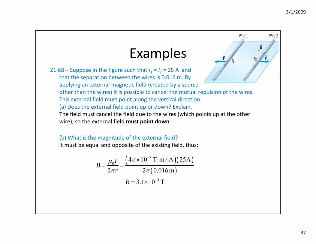
Examples21.68 – Suppose in the figure such that I1 = I2 = 25 A and
that the separation between the wires is 0.016 m. Byapplying an external magnetic field (created by a sourceother than the wires) it is possible to cancel the mutual repulsion of the wires. This external field must point along the vertical direction.(a) Does the external field point up or down? Explain.The field must cancel the field due to the wires (which points up at the other wire), so the external field must point down.
(b) What is the magnitude of the external field?It must be equal and opposite of the existing field, thus:
( )( )( )
70
4
4 10 T m / A 25
2 2 0.016 m
3.1 10 T
IBr
B
πμπ π
−
−
× ⋅ Α= =
= ×
3/1/2009
38
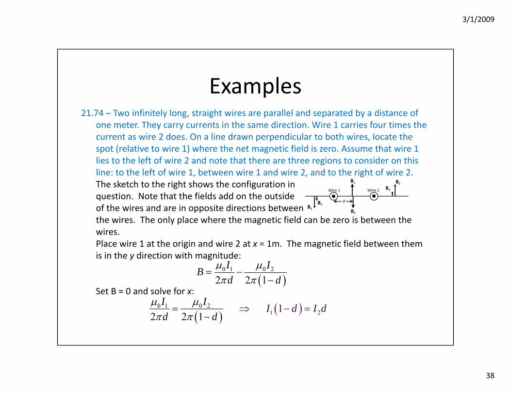
Examples21.74 – Two infinitely long, straight wires are parallel and separated by a distance of
one meter. They carry currents in the same direction. Wire 1 carries four times the current as wire 2 does. On a line drawn perpendicular to both wires, locate the spot (relative to wire 1) where the net magnetic field is zero. Assume that wire 1 lies to the left of wire 2 and note that there are three regions to consider on this line: to the left of wire 1, between wire 1 and wire 2, and to the right of wire 2.The sketch to the right shows the configuration inquestion. Note that the fields add on the outsideof the wires and are in opposite directions betweenthe wires. The only place where the magnetic field can be zero is between the wires.Place wire 1 at the origin and wire 2 at x = 1m. The magnetic field between them is in the y direction with magnitude:
Set B = 0 and solve for x:
Wire 1 Wire 2
B1
B1
B1 B2
B2
B2
d
( )0 1 0 2
2 2 1I IBd d
μ μπ π
= −−
( ) ( )10 1 0
22 1
2 2 1I Id d
I d I dμ μπ π
⇒ − ==−
3/1/2009
39
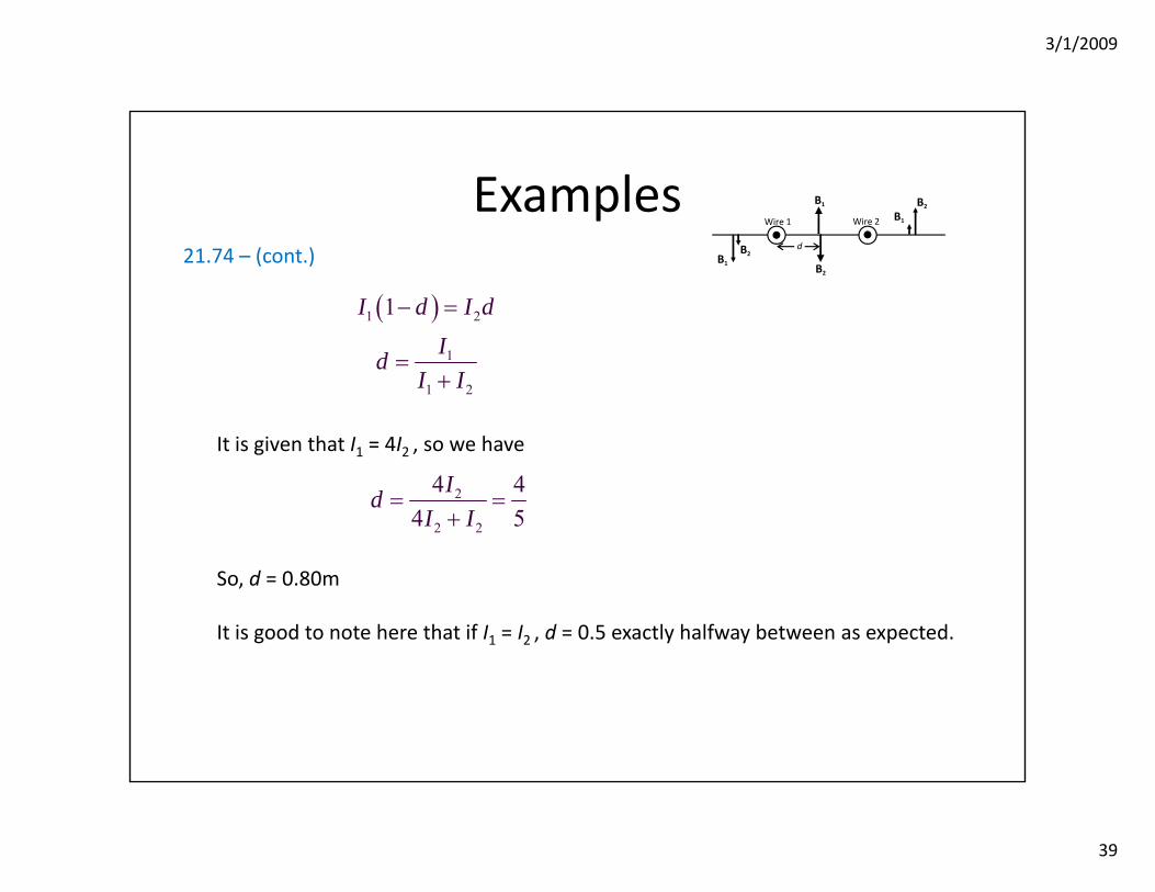
Examples21.74 – (cont.)
It is given that I1 = 4I2 , so we have
So, d = 0.80m
It is good to note here that if I1 = I2 , d = 0.5 exactly halfway between as expected.
Wire 1 Wire 2
B1
B1
B1 B2
B2
B2
d
( )1 2
1
1 2
1I d I dId
I I
− =
=+
2
2 2
4 44 5
IdI I
= =+
3/1/2009
40
Examples
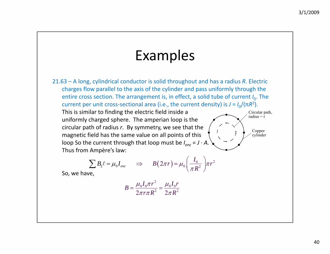
21.63 – A long, cylindrical conductor is solid throughout and has a radius R. Electric charges flow parallel to the axis of the cylinder and pass uniformly through the entire cross section. The arrangement is, in effect, a solid tube of current I0. The current per unit cross‐sectional area (i.e., the current density) is J = I0/(πR2). This is similar to finding the electric field inside auniformly charged sphere. The amperian loop is thecircular path of radius r. By symmetry, we see that themagnetic field has the same value on all points of thisloop So the current through that loop must be Ienc = J ∙ A.Thus from Ampère’s law:
So, we have,
Circular path,radius = r
Coppercylinder
( )020
0 22encIBI rR
B rπ μπ
μ π⎛ ⎞⇒ = ⎜⎝
= ⎟⎠
∑
20 0 0 0
2 22 2I r I rBr R R
μ π μπ π π
= =
3/1/2009
41
Ampère’s Law andSolenoids
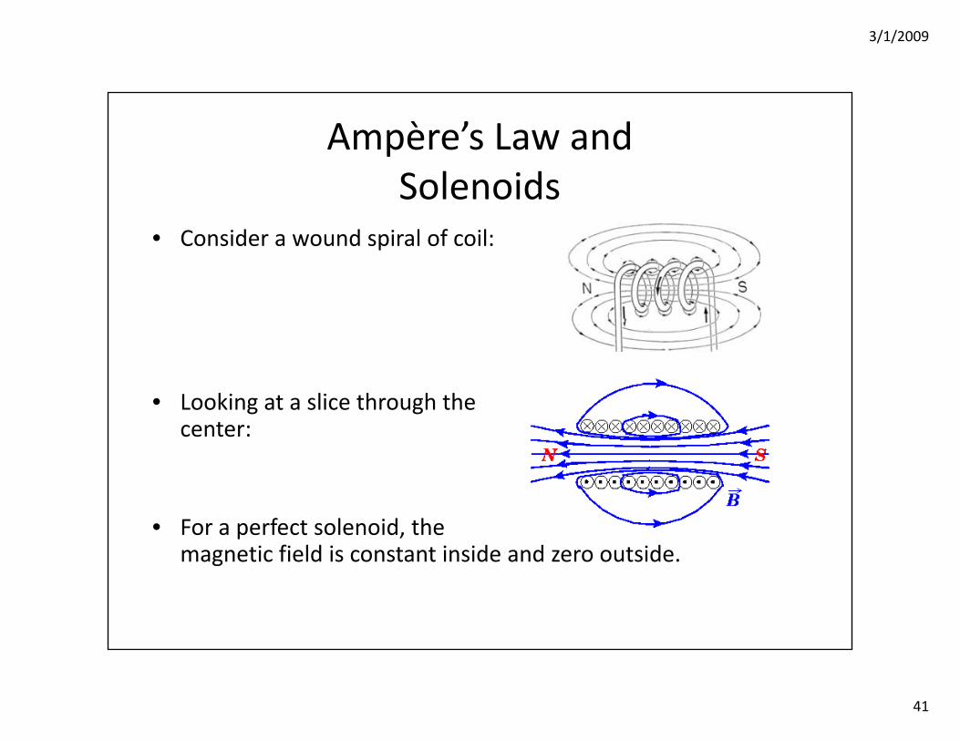
• Consider a wound spiral of coil:
• Looking at a slice through thecenter:
• For a perfect solenoid, the magnetic field is constant inside and zero outside.
3/1/2009
42
Ampère’s Law andSolenoids
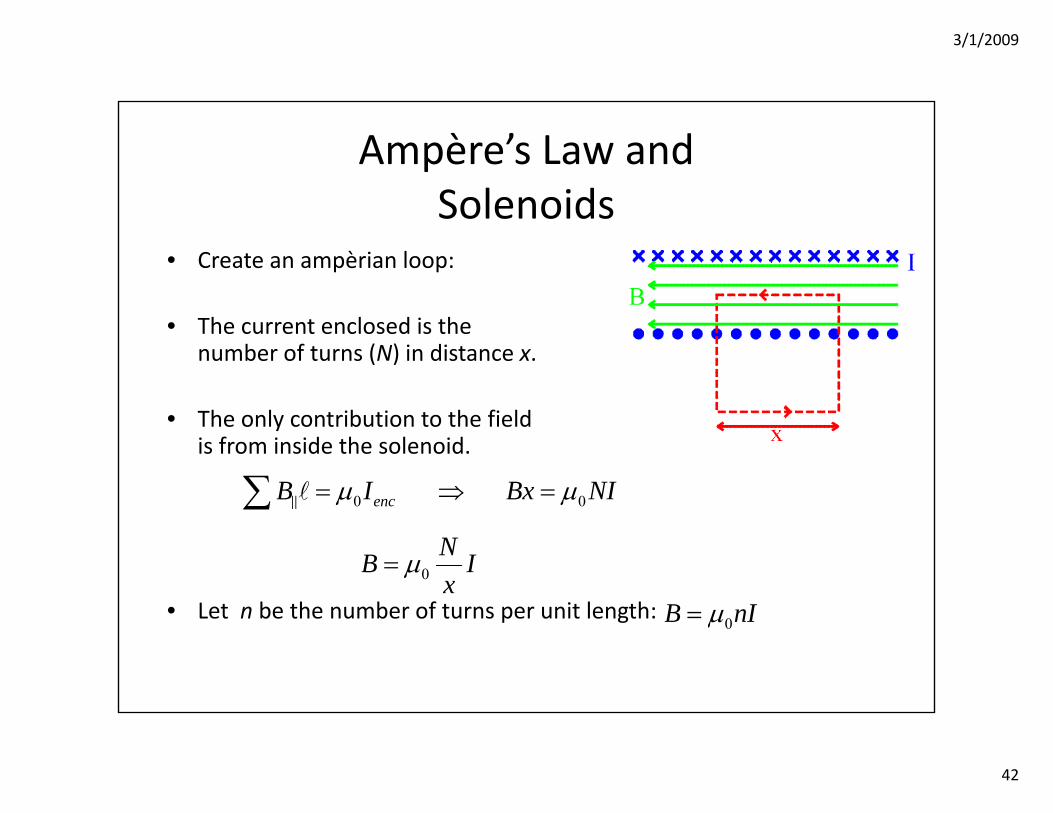
• Create an ampèrian loop:
• The current enclosed is thenumber of turns (N) in distance x.
• The only contribution to the fieldis from inside the solenoid.
• Let n be the number of turns per unit length:
0 0encB I Bx NIμ μ= ⇒ =∑
0NB Ix
μ=
0B nIμ=
3/1/2009
43
Electromagnetic Induction
• We have seen
– Magnetic fields cause forces on current carrying wires.
– Current carrying wires create magnetic fields.
• Now, we see that a changing magnetic field can cause current to flow in a wire.
– Moving a magnet around a wire (changing the field) will cause current.
– Moving the wire in a magnetic field will cause current.
3/1/2009
44
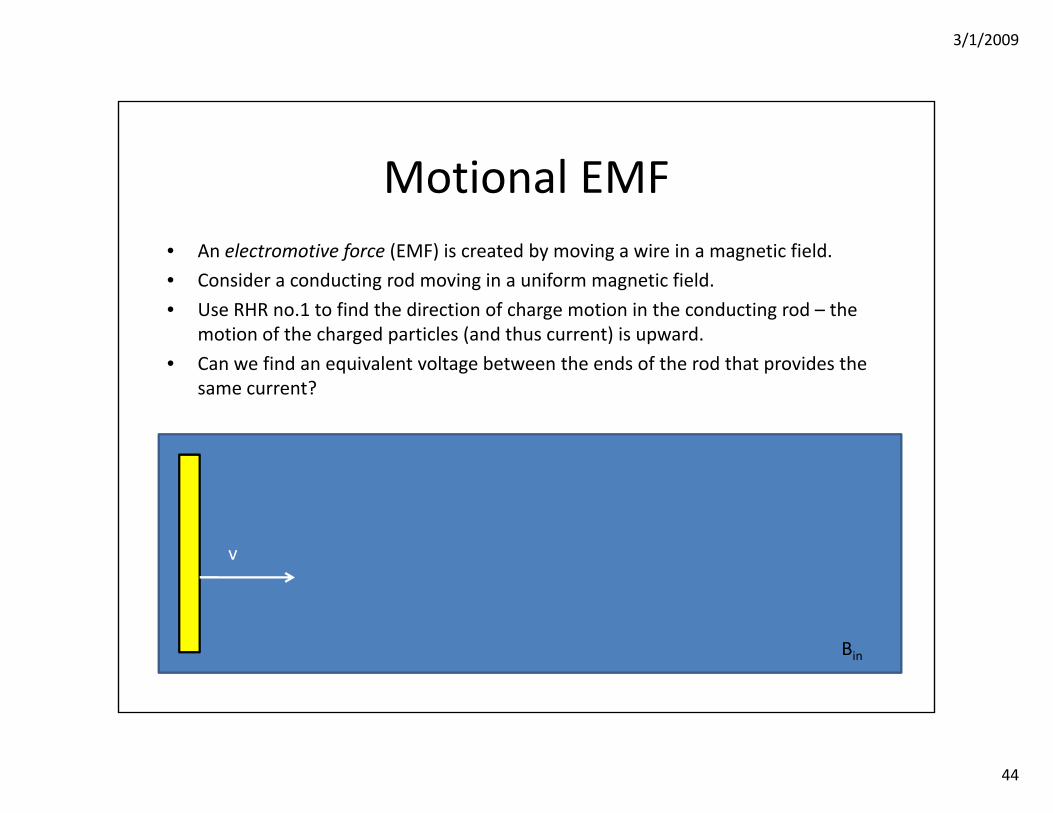
Motional EMF• An electromotive force (EMF) is created by moving a wire in a magnetic field.
• Consider a conducting rod moving in a uniform magnetic field.
• Use RHR no.1 to find the direction of charge motion in the conducting rod – the motion of the charged particles (and thus current) is upward.
• Can we find an equivalent voltage between the ends of the rod that provides the same current?
Bin
v

3/1/2009
45
Motional EMF• The force on a charge due to an electric field is qE.
• But, the electric field is E = V/L (where L is the length of the rod).
• Setting this equal to the magnetic force:
• Where the velocity, magnetic field and length of rod are all mutually perpendicular.
• We use a script E to represent motional EMF
BL=E υ
Vq q B V BLL= ⇒ =υ υ
3/1/2009
46
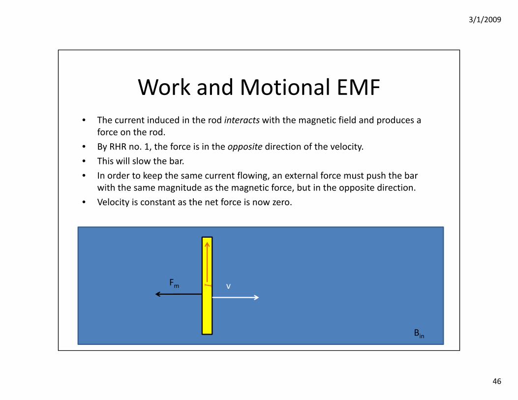
• The current induced in the rod interacts with the magnetic field and produces a force on the rod.
• By RHR no. 1, the force is in the opposite direction of the velocity.
• This will slow the bar.
• In order to keep the same current flowing, an external force must push the bar with the same magnitude as the magnetic force, but in the opposite direction.
• Velocity is constant as the net force is now zero.
Bin
v
Work and Motional EMF
IFm
3/1/2009
47
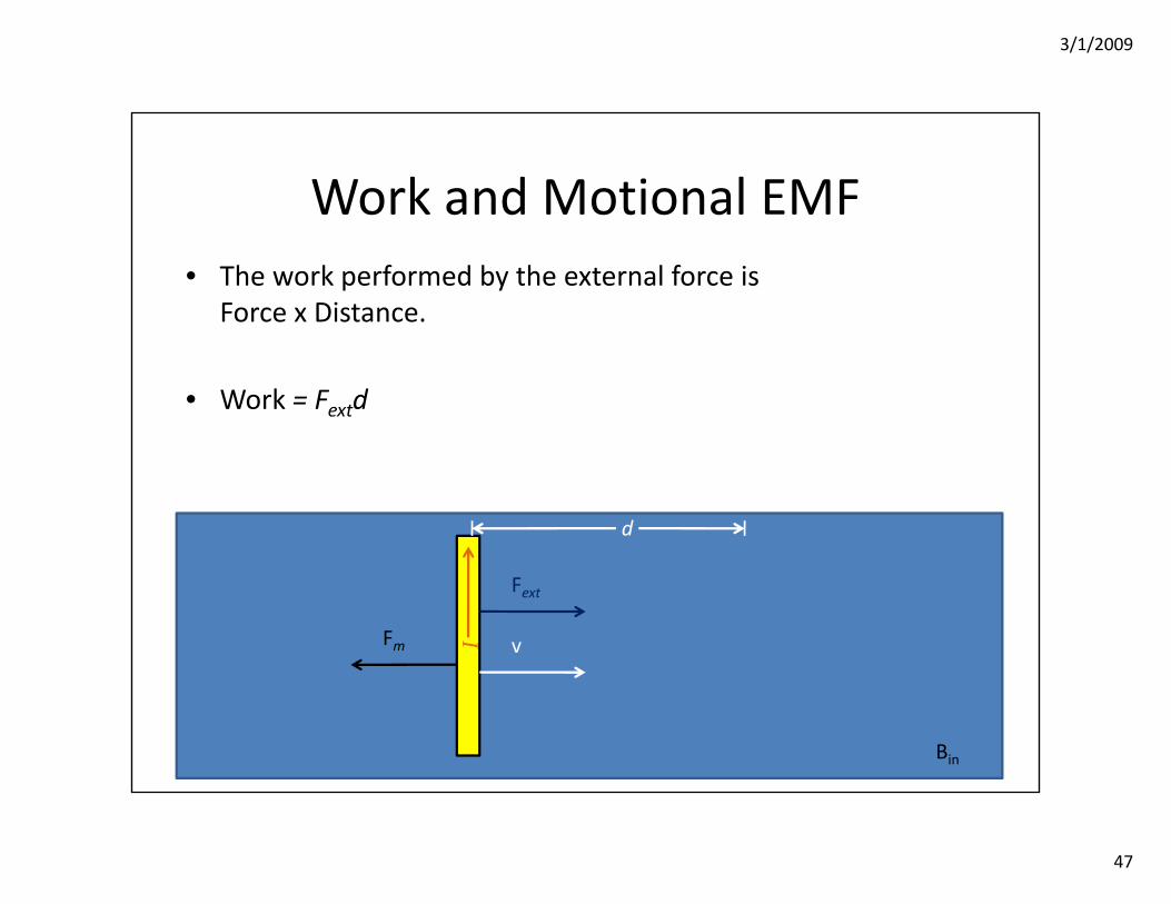
• The work performed by the external force isForce x Distance.
• Work = Fextd
Bin
Work and Motional EMF
vIFm
Fext
d
3/1/2009
48
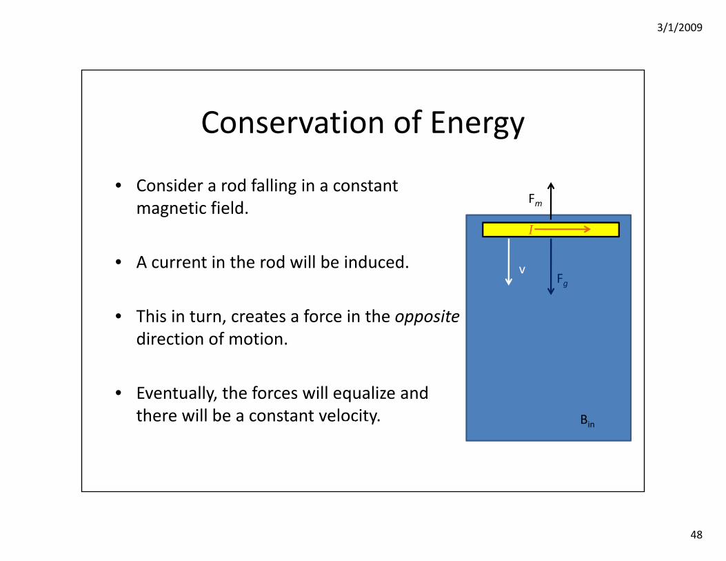
Conservation of Energy
• Consider a rod falling in a constant magnetic field.
• A current in the rod will be induced.
• This in turn, creates a force in the oppositedirection of motion.
• Eventually, the forces will equalize and there will be a constant velocity. Bin
v
I
Fm
Fg
mg ILB=
3/1/2009
49
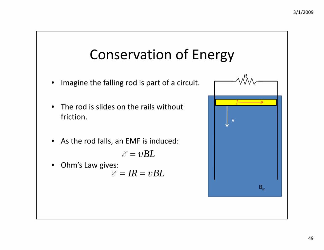
Conservation of Energy
• Imagine the falling rod is part of a circuit.
• The rod is slides on the rails without friction.
• As the rod falls, an EMF is induced:
• Ohm’s Law gives:
Bin
BL=E υ
IR BL= =E υ
v
R
I
3/1/2009
50
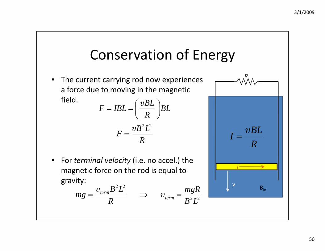
Conservation of Energy
• The current carrying rod now experiences a force due to moving in the magnetic field.
• For terminal velocity (i.e. no accel.) the magnetic force on the rod is equal to gravity:
Bin
2 2
BLF IBL BLR
B LFR
⎛ ⎞= = ⎜ ⎟⎝ ⎠
=
υ
υ
v2 2
2 2term
termB L mgRmgR B L
= ⇒ =υ
υ
R
BLIR
=υ
I
3/1/2009
51
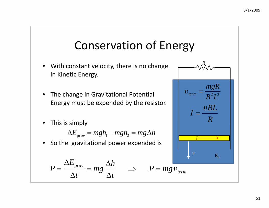
Conservation of Energy
• With constant velocity, there is no change in Kinetic Energy.
• The change in Gravitational Potential Energy must be expended by the resistor.
• This is simply
• So the gravitational power expended is
Bin
1 2gravE mgh mgh mg hΔ = − = Δ
v
gravterm
E hP mg P mgt t
Δ Δ= = ⇒ =
Δ Δυ
R
2 2termmgRB L
=υ
BLIR
=υ
I
3/1/2009
52
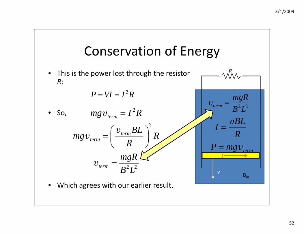
Conservation of Energy• This is the power lost through the resistor
R:
• So,
• Which agrees with our earlier result.Bin
2P VI I R= =
v
2
2
2 2
term
termterm
term
mg I R
BLmg RR
mgRB L
=
⎛ ⎞= ⎜ ⎟⎝ ⎠
=
υ
υυ
υ
R
termP mg= υI
2 2termmgRB L
=υ
BLIR
=υ
3/1/2009
53
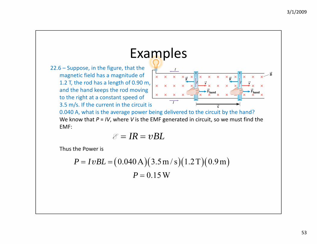
Examples22.6 – Suppose, in the figure, that the
magnetic field has a magnitude of1.2 T, the rod has a length of 0.90 m,and the hand keeps the rod movingto the right at a constant speed of3.5 m/s. If the current in the circuit is0.040 A, what is the average power being delivered to the circuit by the hand?We know that P = IV, where V is the EMF generated in circuit, so we must find the EMF:
Thus the Power is
IR BL= =E υ
( )( )( )( )0.040A 3.5m / s 1.2T 0.9 m0.15W
P I BLP
= =
=
υ
3/1/2009
54
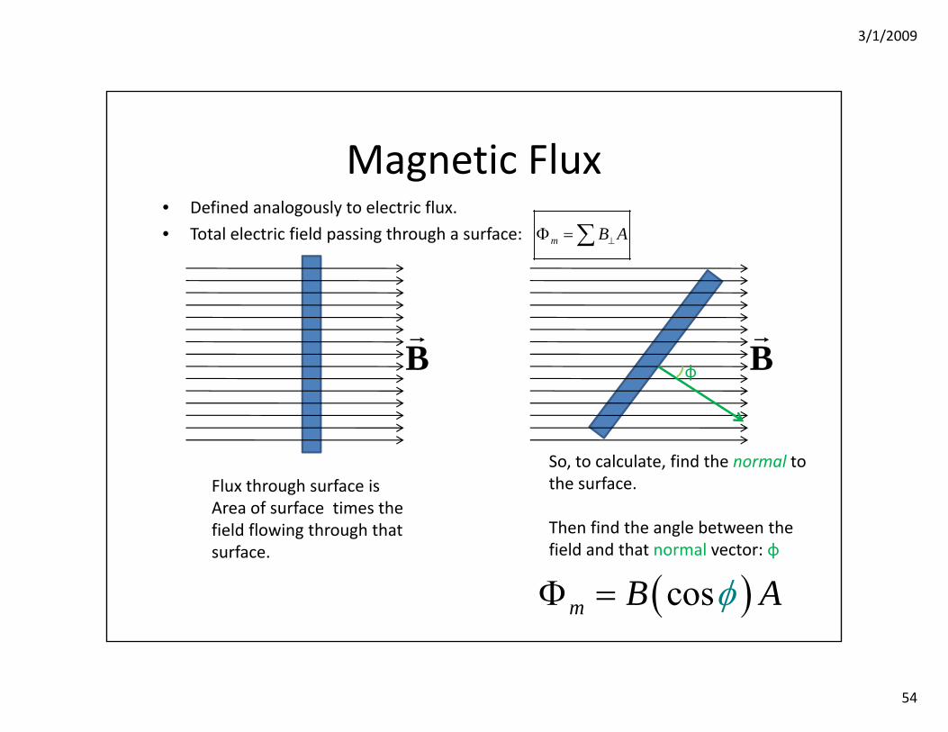
Magnetic Flux
m B A⊥Φ =∑
B
Flux through surface is Area of surface times the field flowing through that surface.
B
So, to calculate, find the normal to the surface.
Then find the angle between the field and that normal vector: φ
( )cosm B AφΦ =
φ
• Defined analogously to electric flux.
• Total electric field passing through a surface:
3/1/2009
55
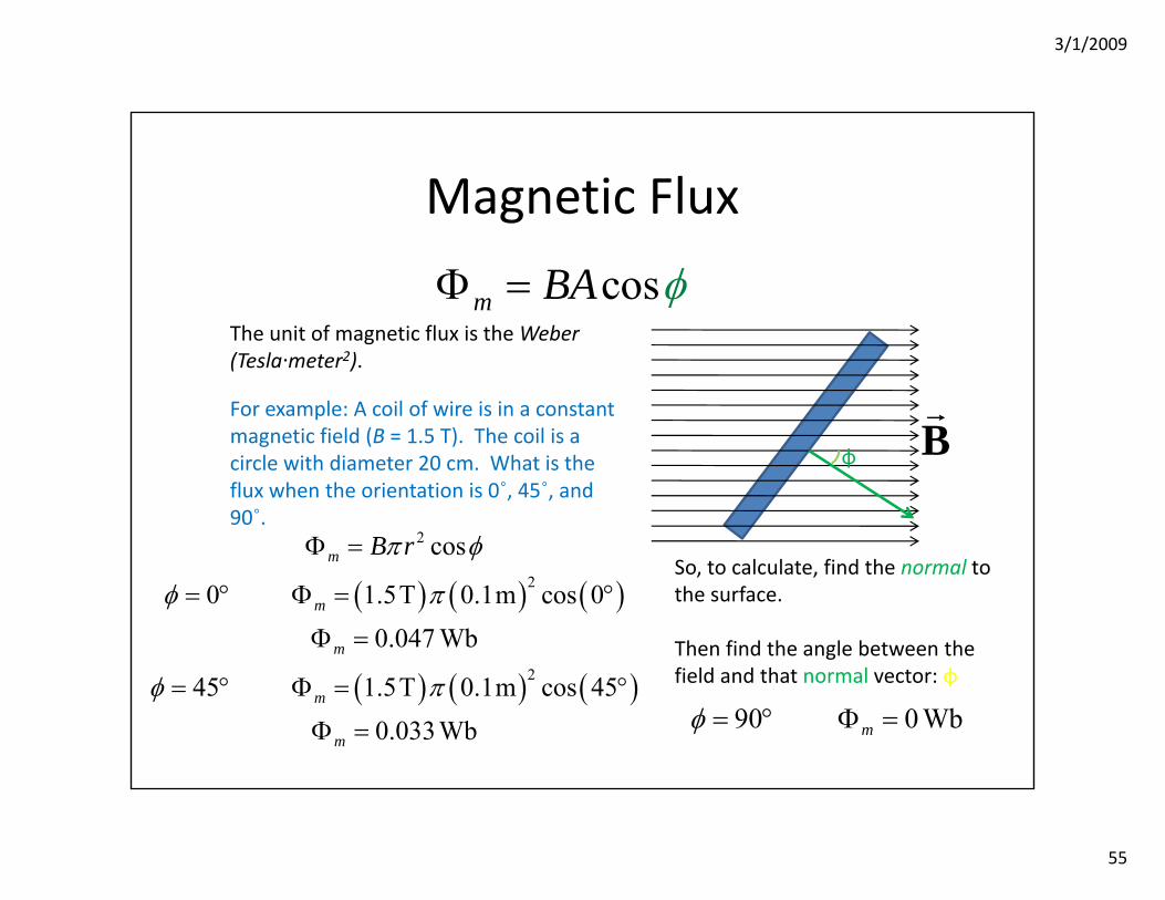
Magnetic Flux
cosm BA φΦ =The unit of magnetic flux is the Weber (Tesla·meter2).
For example: A coil of wire is in a constant magnetic field (B = 1.5 T). The coil is a circle with diameter 20 cm. What is the flux when the orientation is 0˚, 45˚, and 90˚.
( ) ( ) ( )
( ) ( ) ( )
2
2
2
cos
0 1.5T 0.1m cos 00.047 Wb
45 1.5T 0.1m cos 450.033Wb
m
m
m
m
m
B rπ φ
φ π
φ π
Φ =
= ° Φ = °
Φ =
= ° Φ = °
Φ =
So, to calculate, find the normal to the surface.
Then find the angle between the field and that normal vector: φ
90 0 Wbmφ = ° Φ =
Bφ
3/1/2009
56
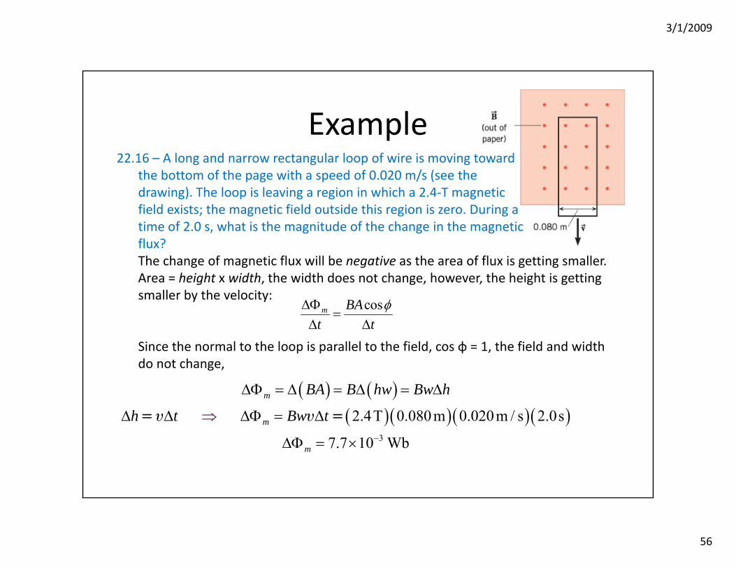
Example22.16 – A long and narrow rectangular loop of wire is moving toward
the bottom of the page with a speed of 0.020 m/s (see thedrawing). The loop is leaving a region in which a 2.4‐T magneticfield exists; the magnetic field outside this region is zero. During atime of 2.0 s, what is the magnitude of the change in the magneticflux? The change of magnetic flux will be negative as the area of flux is getting smaller. Area = height x width, the width does not change, however, the height is getting smaller by the velocity:
Since the normal to the loop is parallel to the field, cos φ = 1, the field and width do not change,
cosm BAt t
φΔΦ=
Δ Δ
( ) ( )( )( )( )( )
3
2.4T 0.080m 0.020m / s 2.0s
7.7 10 Wb
m
m
m
BA B hw Bw h
h t Bw t−
ΔΦ = Δ
⇒
= Δ = Δ
Δ Δ ΔΦ = Δ
ΔΦ = ×
=υ υ =
3/1/2009
57
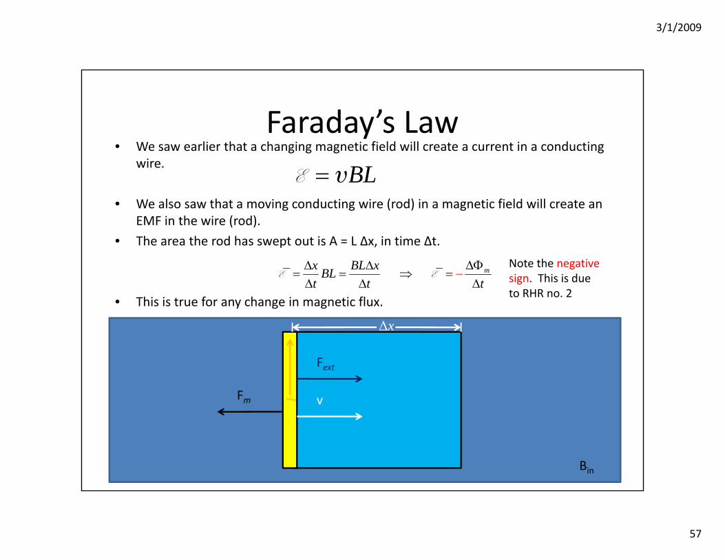
Faraday’s Law• We saw earlier that a changing magnetic field will create a current in a conducting
wire.
• We also saw that a moving conducting wire (rod) in a magnetic field will create an EMF in the wire (rod).
• The area the rod has swept out is A = L Δx, in time Δt.
• This is true for any change in magnetic flux.
BL=E υ
Bin
vIFm
Fext
Δx
mx BL xBLt t t
ΔΦΔ Δ= = ⇒ =Δ
−Δ Δ
E ENote the negative sign. This is due to RHR no. 2
3/1/2009
58
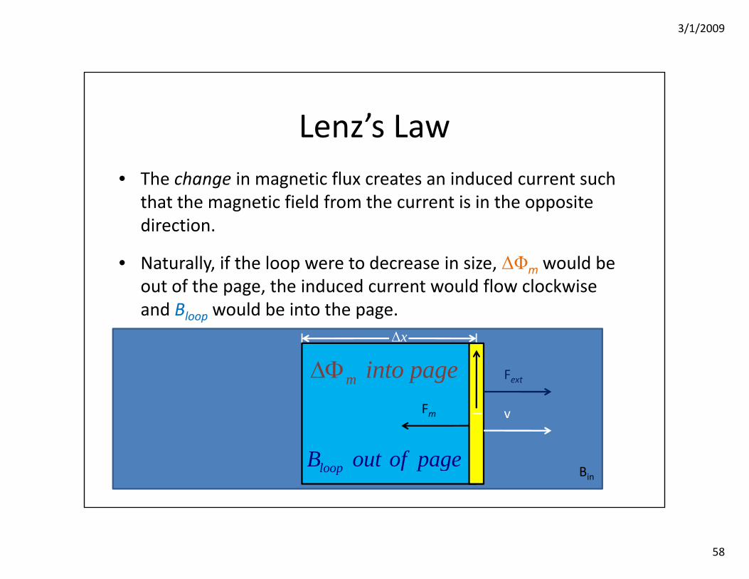
Lenz’s Law• The change in magnetic flux creates an induced current such
that the magnetic field from the current is in the opposite direction.
• Naturally, if the loop were to decrease in size, ΔΦm would be out of the page, the induced current would flow clockwise and Bloop would be into the page.
m
tΔΦ
= −Δ
E
Bin
Δx
vIFm
Fext
loopB out of page
m into pageΔΦ
3/1/2009
59
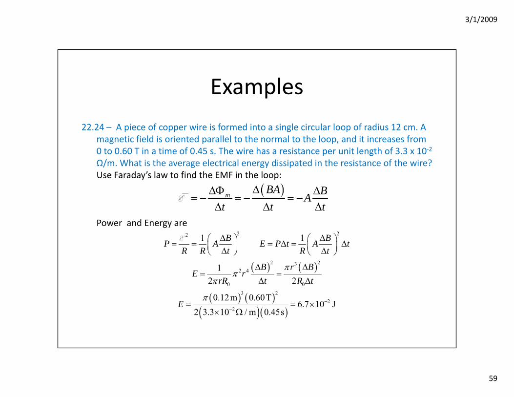
Examples
22.24 – A piece of copper wire is formed into a single circular loop of radius 12 cm. A magnetic field is oriented parallel to the normal to the loop, and it increases from 0 to 0.60 T in a time of 0.45 s. The wire has a resistance per unit length of 3.3 x 10‐2
Ω/m. What is the average electrical energy dissipated in the resistance of the wire?Use Faraday’s law to find the EMF in the loop:
Power and Energy are
( )m BA BAt t t
ΔΔΦ Δ= − = − = −
Δ Δ ΔE
( ) ( )
( ) ( )( )( )
2 22
2 232 4
0 03 2
22
1 1
12 2
0.12m 0.60T6.7 10 J
2 3.3 10 / m 0.45s
B BP A E P t A tR R t R t
B r BE r
rR t R t
E
ππ
π
π −−
Δ Δ⎛ ⎞ ⎛ ⎞= = = Δ = Δ⎜ ⎟ ⎜ ⎟Δ Δ⎝ ⎠ ⎝ ⎠
Δ Δ= =
Δ Δ
= = ×× Ω
E

3/1/2009
60
Examples
22.73 – Two 0.68‐m‐long conducting rods are rotating atthe same speed in opposite directions, and both areperpendicular to a 4.7‐T magnetic field. As the drawingshows, the ends of these rods come to within 1.0 mm of each other as they rotate. Moreover, the fixed ends about which the rods are rotating are connected by a wire, so these ends are at the same electric potential. If a potential difference of 4.5 × 10³ V is required to cause a 1.0‐mm spark in air, what is the angular speed (in rad/s) of the rods when a spark jumps across the gap? Consider one revolution of either rod. The magnitude of the emf induced across the rod is
The angular speed of the rods is ω = 2π/Δt, so . . The rod tips have opposite polarity since they are rotating in opposite directions. Hence, the difference in potentials of the tips is Δ V = BL2 ω.
( )2
= = t
B LABt
πΔ−
Δ ΔE
2= / 2BL ωE
( )( )
3
2 24.5 10 V 2100 rad/s
4.7 T 0.68 mV
BLω Δ ×= = =
3/1/2009
61
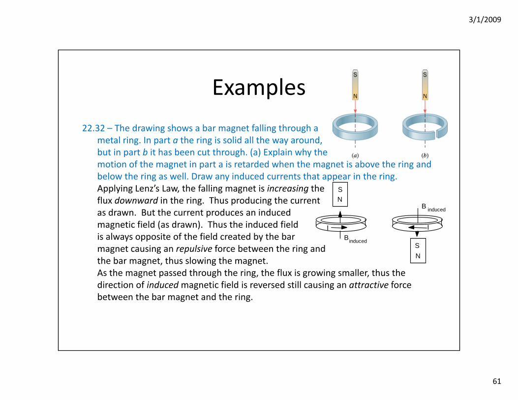
Examples
22.32 – The drawing shows a bar magnet falling through ametal ring. In part a the ring is solid all the way around,but in part b it has been cut through. (a) Explain why themotion of the magnet in part a is retarded when the magnet is above the ring and below the ring as well. Draw any induced currents that appear in the ring.Applying Lenz’s Law, the falling magnet is increasing theflux downward in the ring. Thus producing the currentas drawn. But the current produces an inducedmagnetic field (as drawn). Thus the induced fieldis always opposite of the field created by the barmagnet causing an repulsive force between the ring andthe bar magnet, thus slowing the magnet.As the magnet passed through the ring, the flux is growing smaller, thus the direction of inducedmagnetic field is reversed still causing an attractive force between the bar magnet and the ring.
SN
SN
BI I
induced
B induced

3/1/2009
62
Examples
22.32 – (cont.) – (b) Explain why the motion of the magnetis unaffected by the ring in part b.Simply put, in part b, the ring is broken so no current flows,therefore without a current, there is no inducedmagnetic field even though there is still a changing flux in the ring.
3/1/2009
63
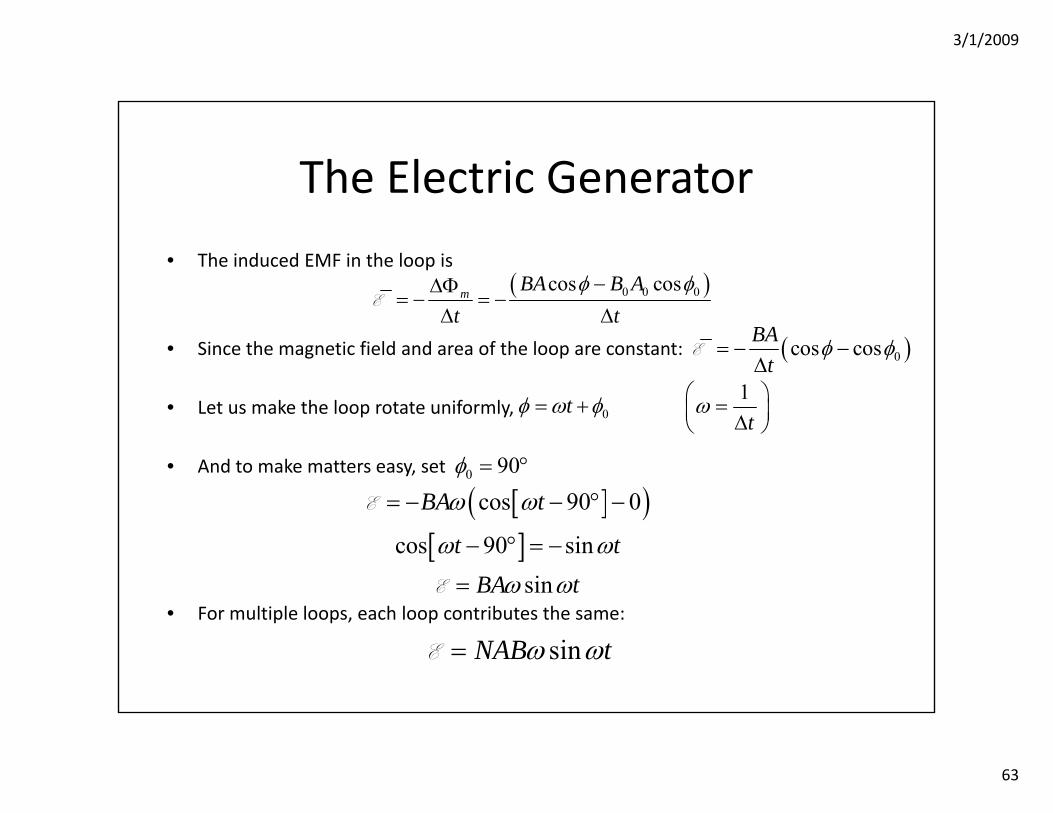
The Electric Generator
• The induced EMF in the loop is
• Since the magnetic field and area of the loop are constant:
• Let us make the loop rotate uniformly,
• And to make matters easy, set
• For multiple loops, each loop contributes the same:
( )0 0 0cos cosm BA B At t
φ φ−ΔΦ= − = −
Δ ΔE
( )0cos cosBAt
φ φ= − −Δ
E
01tt
φ ω φ ω⎛ ⎞= + =⎜ ⎟Δ⎝ ⎠
0 90φ = °
[ ]( )[ ]
cos 90 0
cos 90 sinsin
BA t
t tBA t
ω ω
ω ω
ω ω
= − − ° −
− ° = −
=
E
E
sinNAB tω ω=E
3/1/2009
64
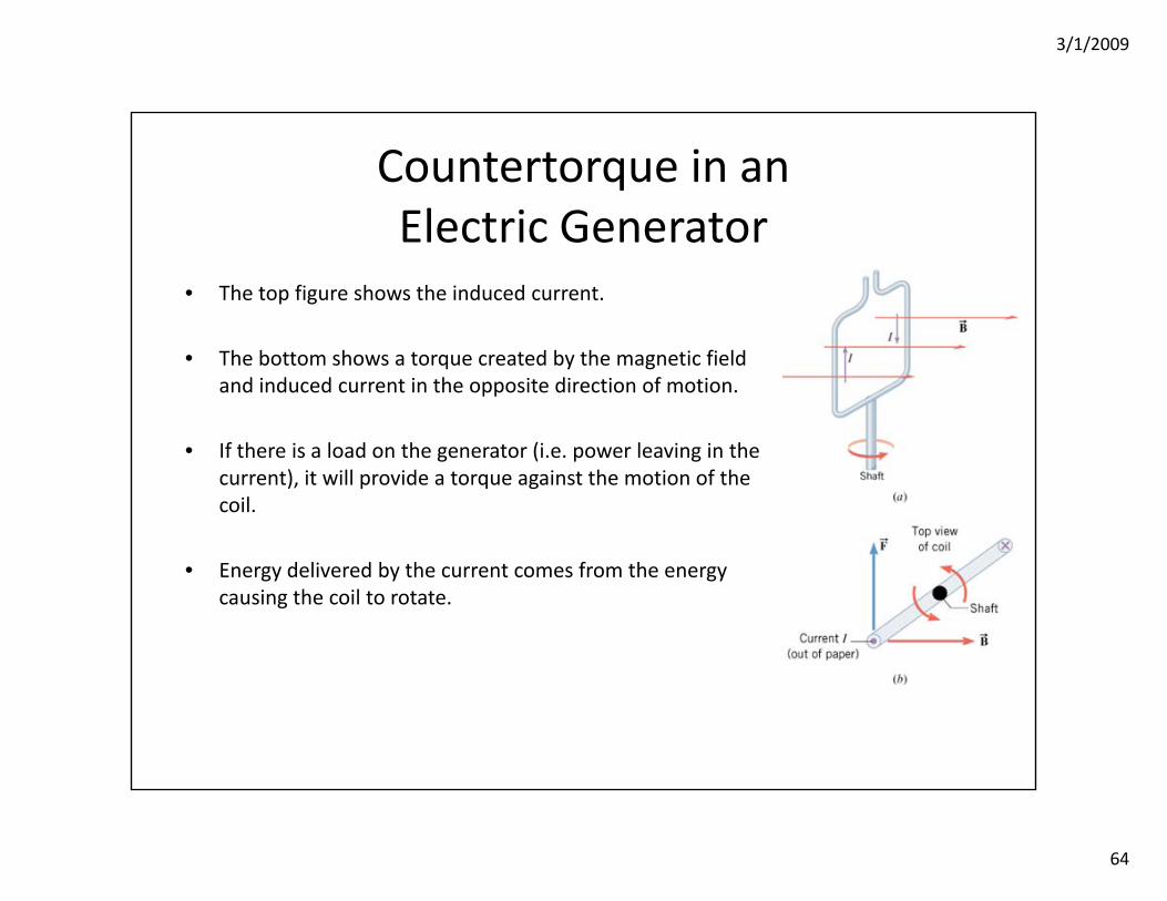
Countertorque in anElectric Generator
• The top figure shows the induced current.
• The bottom shows a torque created by the magnetic field and induced current in the opposite direction of motion.
• If there is a load on the generator (i.e. power leaving in the current), it will provide a torque against the motion of the coil.
• Energy delivered by the current comes from the energy causing the coil to rotate.
3/1/2009
65
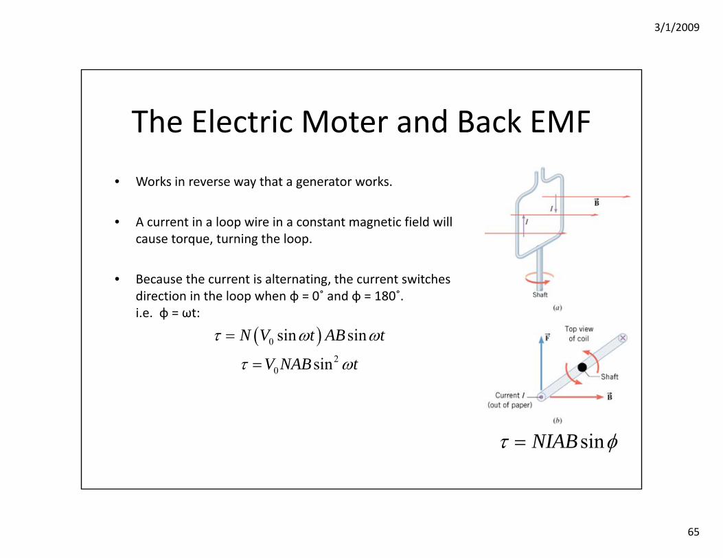
The Electric Moter and Back EMF
• Works in reverse way that a generator works.
• A current in a loop wire in a constant magnetic field will cause torque, turning the loop.
• Because the current is alternating, the current switches direction in the loop when φ = 0˚ and φ = 180˚.i.e. φ = ωt:
sinNIABτ φ=
( )0
20
sin sin
sin
N V t AB t
V NAB t
τ ω ω
τ ω
=
=
3/1/2009
66
Back EMF in an Electric Motor
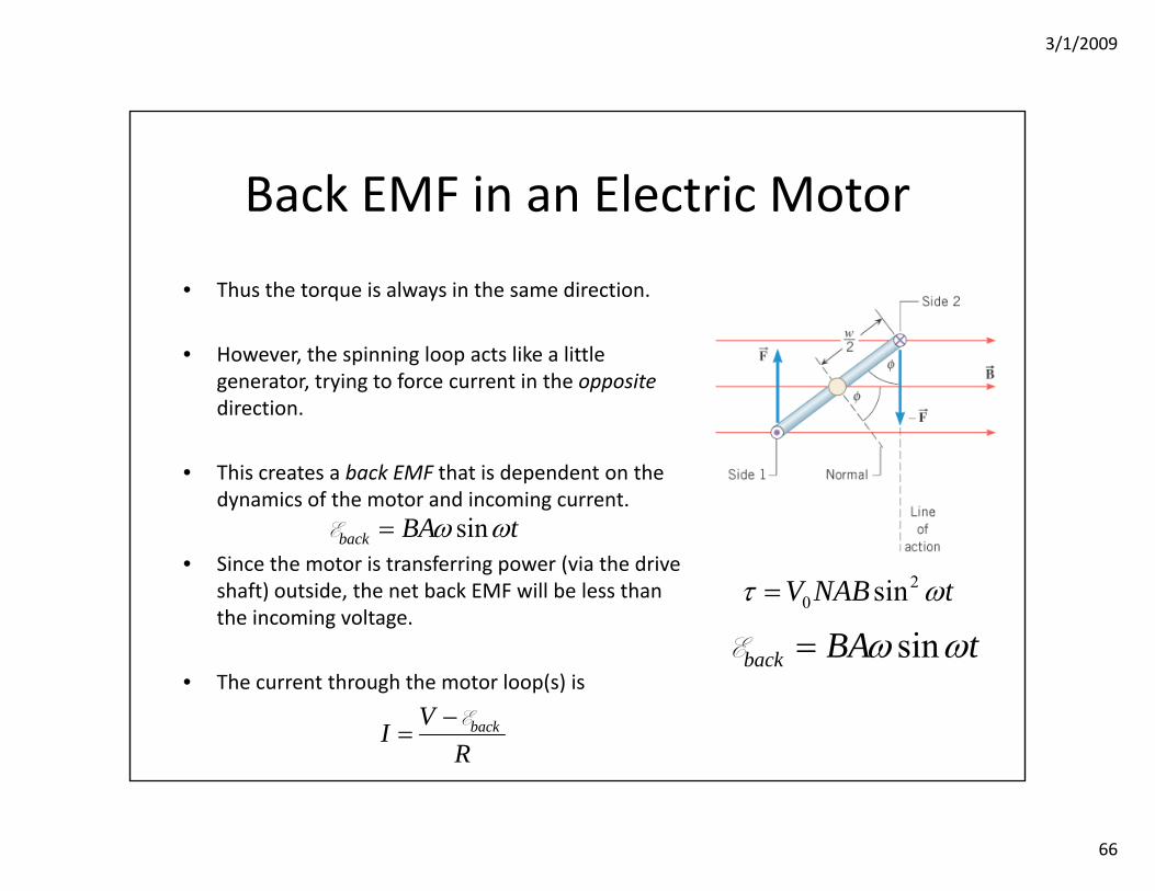
• Thus the torque is always in the same direction.
• However, the spinning loop acts like a little generator, trying to force current in the oppositedirection.
• This creates a back EMF that is dependent on the dynamics of the motor and incoming current.
• Since the motor is transferring power (via the drive shaft) outside, the net back EMF will be less than the incoming voltage.
• The current through the motor loop(s) is
20 sinV NAB tτ ω=
sinback BA tω ω=E
backVIR−
=E
sinback BA tω ω=E

3/1/2009
67
Example
22.74 – The armature of an electric drill motor has a resistance of 15.0Ω. When connected to a 120.0‐V outlet, the motor rotates at its normal speed and develops a back emf of 108 V. (a) What is the current through the motor?
(b) If the armature freezes up due to a lack of lubrication in the bearings and can no longer rotate, what is the current in the stationary armature?Since there is no back emf, Ohm’s law applies:
(c) What is the current when the motor runs at only half speed?Half speed implies the angular speed is reduced by ½, so the back EMF must also be reduced by ½.
120.0 V 108V 0.80 A15
backVIR− −
= = =Ω
E
120.0 V 0 V 8.0 A15
backVIR− −
= = =Ω
E
120.0 V 54 V 4.40 A15
backVIR− −
= = =Ω
E
3/1/2009
68
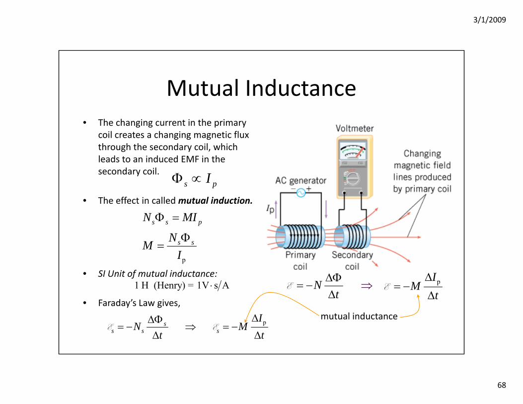
Mutual Inductance• The changing current in the primary
coil creates a changing magnetic flux through the secondary coil, which leads to an induced EMF in the secondary coil.
• The effect in called mutual induction.
• SI Unit of mutual inductance:
• Faraday’s Law gives,
pIM
tΔ
= −Δ
E
mutual inductance
1 H (Henry) = 1V s A⋅ Nt
Δ− ⇒
Φ=
ΔE
s pIΦ ∝
p
s s p
s s
N MI
NMI
Φ =
Φ=
pss s s
IN M
t tΔΔΦ
= − ⇒ = −Δ Δ
E E
3/1/2009
69
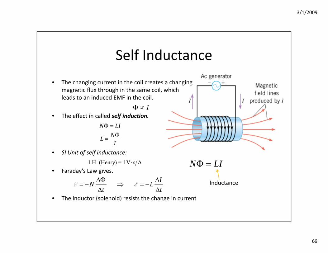
Self Inductance
• The changing current in the coil creates a changing magnetic flux through in the same coil, whichleads to an induced EMF in the coil.
• The effect in called self induction.
• SI Unit of self inductance:
• Faraday’s Law gives.
• The inductor (solenoid) resists the change in current
Inductance
1 H (Henry) = 1V s A⋅
IΦ ∝
N LIΦ =
N LINLI
Φ =Φ
=
IN Lt t
ΔΦ Δ= − ⇒ = −
Δ ΔE E
3/1/2009
70
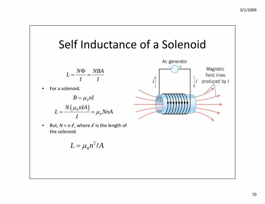
Self Inductance of a Solenoid
• For a solenoid.
• But, N = n l , where l is the length of the solenoid.
( )0
00
B nIN nIA
L NnAI
μ
μμ
=
= =
N NBALI IΦ
= =
20L n Aμ=

3/1/2009
71
Self Inductance of a Solenoid
An inductor is made by tightly winding 0.30 mm diameter wire around a 4.0 mm diameter cylinder.What length cylinder has an inductance of 10 μH?
20L n Aμ=
( ) ( )
5
2220 7
1 10 H1m4 10 T m / A .002m
0.003m5.7 cm
Ln Aμ
π π
−
−
×= =
⎛ ⎞× ⋅ ⎜ ⎟⎝ ⎠
=
3/1/2009
72
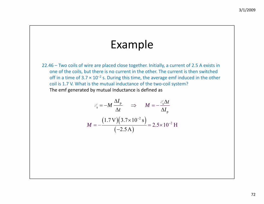
Example
22.46 – Two coils of wire are placed close together. Initially, a current of 2.5 A exists in one of the coils, but there is no current in the other. The current is then switched off in a time of 3.7 × 10⁻² s. During this time, the average emf induced in the other coil is 1.7 V. What is the mutual inductance of the two‐coil system?The emf generated by mutual Inductance is defined as
( )( )( )
p
2
p
21.7 V 3.7 12.
0 s
2.5A5 10 H
ss
I tMt
M
M
I
−−
Δ Δ= −
Δ Δ
×
⇒ = −
= − = ×−
EE
3/1/2009
73
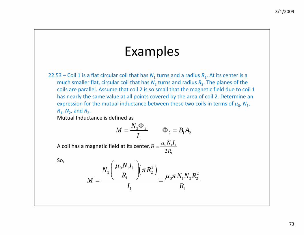
Examples
22.53 – Coil 1 is a flat circular coil that has N1 turns and a radius R1. At its center is a much smaller flat, circular coil that has N2 turns and radius R2. The planes of the coils are parallel. Assume that coil 2 is so small that the magnetic field due to coil 1 has nearly the same value at all points covered by the area of coil 2. Determine an expression for the mutual inductance between these two coils in terms of μ0, N1, R1, N2, and R2.Mutual Inductance is defined as
A coil has a magnetic field at its center,
So,
2 22 1 2
1
NM B AIΦ
= Φ =
0 1 1
12N IBR
μ=
( )20 1 12 2 2
1 0 1 2 2
1 1
N IN RR N N RM
I R
μ πμ π
⎛ ⎞⎜ ⎟⎝ ⎠= =
3/1/2009
74
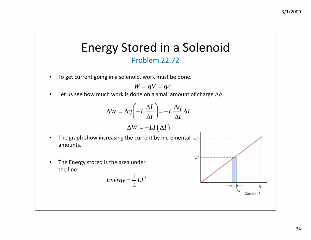
Energy Stored in a SolenoidProblem 22.72
• To get current going in a solenoid, work must be done.
• Let us see how much work is done on a small amount of charge Δq.
• The graph show increasing the current by incrementalamounts.
• The Energy stored is the area underthe line:
W qV q= = E
( )
I qW q L L It t
W LI I
Δ Δ⎛ ⎞Δ = Δ − = − Δ⎜ ⎟Δ Δ⎝ ⎠Δ = − Δ
212
Energy LI=
3/1/2009
75
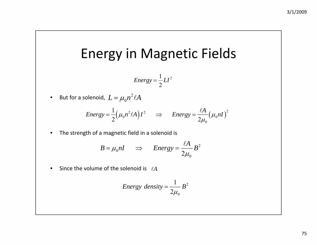
Energy in Magnetic Fields
• But for a solenoid,
• The strength of a magnetic field in a solenoid is
• Since the volume of the solenoid is
( ) ( )22 20 0
0
12 2
AEnergy n A I Energy nIμ μμ
= ⇒ =
20
02AB nI Energy Bμμ
= ⇒ =
212
Energy LI=
20L n Aμ=
2
0
12
Energy density Bμ
=
A
3/1/2009
76
Transformers
• In the US, normal electrical power at a wall socket comes in either 120V or 240V.
• But we know that low voltage through transmission lines will waste power:
• For transmitting a large amount of energy, high voltage is desirable (to decrease power lost in the cable).
• But for normal use (and safety) low voltage is preferable.
2VPR
=
3/1/2009
77
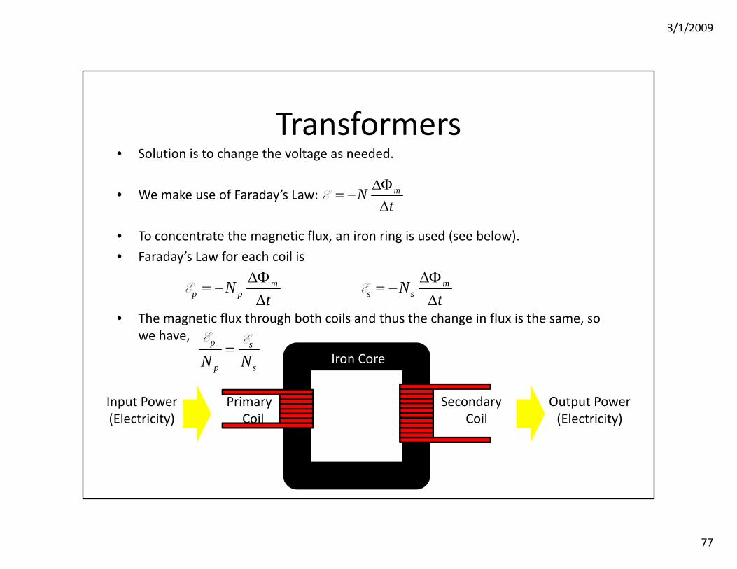
Transformers• Solution is to change the voltage as needed.
• We make use of Faraday’s Law:
• To concentrate the magnetic flux, an iron ring is used (see below).
• Faraday’s Law for each coil is
• The magnetic flux through both coils and thus the change in flux is the same, so we have,
mNt
ΔΦ= −
ΔE
Iron Core
PrimaryCoil
SecondaryCoil
Input Power(Electricity)
Output Power(Electricity)
mp pN
tΔΦ
= −Δ
E ms sN
tΔΦ
= −Δ
E
p s
p sN N=
E E
3/1/2009
78
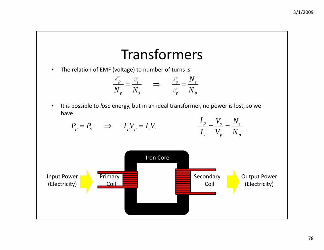
Transformers• The relation of EMF (voltage) to number of turns is
• It is possible to lose energy, but in an ideal transformer, no power is lost, so we have
p s s s
p s p p
NN N N
= ⇒ =E E E
E
p s p p s sP P I V I V= ⇒ = p s s
s p p
I V NI V N
= =
Iron Core
PrimaryCoil
SecondaryCoil
Input Power(Electricity)
Output Power(Electricity)
3/1/2009
79
Transformers
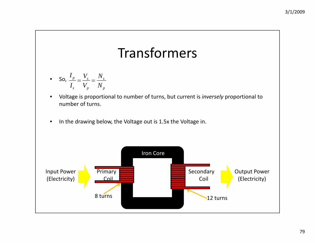
• So,
• Voltage is proportional to number of turns, but current is inversely proportional to number of turns.
• In the drawing below, the Voltage out is 1.5x the Voltage in.
p s s
s p p
I V NI V N
= =
12 turns8 turns
Iron Core
PrimaryCoil
SecondaryCoil
Input Power(Electricity)
Output Power(Electricity)
3/1/2009
80
Examples
22.57 – Electric doorbells found in many homes require 10.0 V to operate. To obtain this voltage from the standard 120‐V supply, a transformer is used. Is a step‐up or a step‐down transformer needed, and what is its turns ratio Ns/Np?We want reduced voltage, so a step down transformer is needed, the ratio for voltage is 1:12, so that must be the ratio of turns in the secondary to primary.
22.58 – The resistances of the primary and secondary coils of a transformer are 56Ωand 14Ω, respectively. Both coils are made from lengths of the same copper wire. The circular turns of each coil have the same diameter. Find the turns ratio Ns/Np.If the coils are made out of the same wire, then the only difference that explains different resistances is different lengths. Thus the 56Ω wire must be four times longer than the 14Ω resistor. If each coil is the same shape and size, there must be four times the number of primary coils than secondary, hence 1:4 is Ns:Np