Photogrammetric Accuracy and Modeling of … Accuracy and Modeling of Consumer Cameras Jonas...
11
Photogrammetric Accuracy and Modeling of Consumer Cameras Jonas Vautherin, Klaus Schneider-Zapp, Hon Fai Choi, Venera Chovancova, Alexis Glass and Christoph Strecha Key words: Mapping, Motion Estimation, Rolling Shutter Modeling, CMOS, UAVs, Drones, Archeology SUMMARY Unmanned aerial vehicles (UAVs) are becoming increasingly popular in professional mapping for stockpile analysis, construction site monitoring, and many other applications. Due to their robustness and competitive pricing, consumer UAVs are used more and more for these applications, but they are usually equipped with rolling shutter cameras. This is a significant obstacle when it comes to extracting high accuracy measurements using available photogrammetry software packages. In this paper, we evaluate the impact of the rolling shutter cameras of typical consumer UAVs on the accuracy of a 3D reconstruction. Here to, we use Pix4Dmapper 3.0 software to compare traditional (non rolling shutter) camera models against a newly implemented rolling shutter model with respect to both the accuracy of geo-referenced validation points and to the quality of the motion estimation. Multiple datasets have been acquired using popular quadcopters (DJI Phantom 2 Vision+, DJI Inspire 1 and 3DR Solo) following a grid flight plan. The bundle block adjustment of each dataset shows a significant accuracy improvement on validation ground control points when applying the new rolling shutter camera model for flights at higher speed (8m/s). Competitive accuracies can be obtained by using the rolling shutter model, although global shutter cameras are still superior. Furthermore, we are able to show that the speed of the drone (and its direction) can be solely estimated from the rolling shutter effect of the camera.
Transcript of Photogrammetric Accuracy and Modeling of … Accuracy and Modeling of Consumer Cameras Jonas...
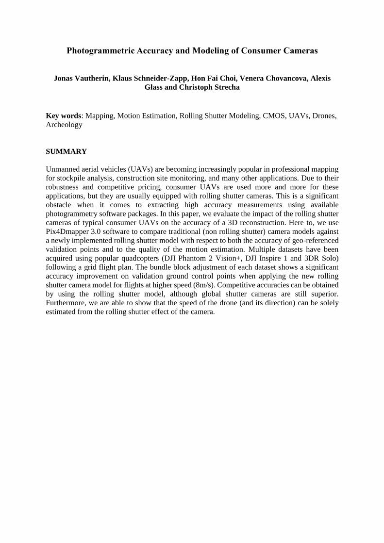
Photogrammetric Accuracy and Modeling of Consumer Cameras
Jonas Vautherin, Klaus Schneider-Zapp, Hon Fai Choi, Venera Chovancova, Alexis
Glass and Christoph Strecha
Key words: Mapping, Motion Estimation, Rolling Shutter Modeling, CMOS, UAVs, Drones,
Archeology
SUMMARY
Unmanned aerial vehicles (UAVs) are becoming increasingly popular in professional mapping
for stockpile analysis, construction site monitoring, and many other applications. Due to their
robustness and competitive pricing, consumer UAVs are used more and more for these
applications, but they are usually equipped with rolling shutter cameras. This is a significant
obstacle when it comes to extracting high accuracy measurements using available
photogrammetry software packages. In this paper, we evaluate the impact of the rolling shutter
cameras of typical consumer UAVs on the accuracy of a 3D reconstruction. Here to, we use
Pix4Dmapper 3.0 software to compare traditional (non rolling shutter) camera models against
a newly implemented rolling shutter model with respect to both the accuracy of geo-referenced
validation points and to the quality of the motion estimation. Multiple datasets have been
acquired using popular quadcopters (DJI Phantom 2 Vision+, DJI Inspire 1 and 3DR Solo)
following a grid flight plan. The bundle block adjustment of each dataset shows a significant
accuracy improvement on validation ground control points when applying the new rolling
shutter camera model for flights at higher speed (8m/s). Competitive accuracies can be obtained
by using the rolling shutter model, although global shutter cameras are still superior.
Furthermore, we are able to show that the speed of the drone (and its direction) can be solely
estimated from the rolling shutter effect of the camera.
Photogrammetric Accuracy and Modeling of Consumer Cameras
Jonas Vautherin, Klaus Schneider-Zapp, Hon Fai Choi, Venera Chovancova, Alexis
Glass and Christoph Strecha
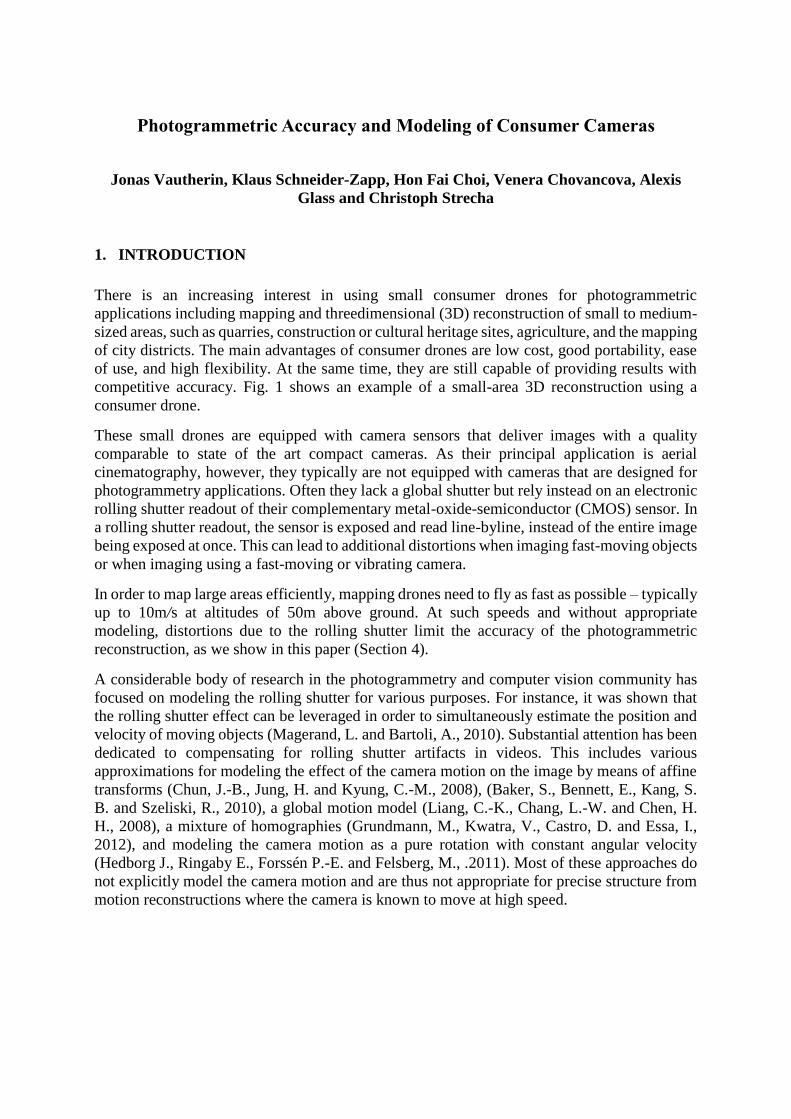
1. INTRODUCTION
There is an increasing interest in using small consumer drones for photogrammetric
applications including mapping and threedimensional (3D) reconstruction of small to medium-
sized areas, such as quarries, construction or cultural heritage sites, agriculture, and the mapping
of city districts. The main advantages of consumer drones are low cost, good portability, ease
of use, and high flexibility. At the same time, they are still capable of providing results with
competitive accuracy. Fig. 1 shows an example of a small-area 3D reconstruction using a
consumer drone.
These small drones are equipped with camera sensors that deliver images with a quality
comparable to state of the art compact cameras. As their principal application is aerial
cinematography, however, they typically are not equipped with cameras that are designed for
photogrammetry applications. Often they lack a global shutter but rely instead on an electronic
rolling shutter readout of their complementary metal-oxide-semiconductor (CMOS) sensor. In
a rolling shutter readout, the sensor is exposed and read line-byline, instead of the entire image
being exposed at once. This can lead to additional distortions when imaging fast-moving objects
or when imaging using a fast-moving or vibrating camera.
In order to map large areas efficiently, mapping drones need to fly as fast as possible – typically
up to 10m/s at altitudes of 50m above ground. At such speeds and without appropriate
modeling, distortions due to the rolling shutter limit the accuracy of the photogrammetric
reconstruction, as we show in this paper (Section 4).
A considerable body of research in the photogrammetry and computer vision community has
focused on modeling the rolling shutter for various purposes. For instance, it was shown that
the rolling shutter effect can be leveraged in order to simultaneously estimate the position and
velocity of moving objects (Magerand, L. and Bartoli, A., 2010). Substantial attention has been
dedicated to compensating for rolling shutter artifacts in videos. This includes various
approximations for modeling the effect of the camera motion on the image by means of affine
transforms (Chun, J.-B., Jung, H. and Kyung, C.-M., 2008), (Baker, S., Bennett, E., Kang, S.
B. and Szeliski, R., 2010), a global motion model (Liang, C.-K., Chang, L.-W. and Chen, H.
H., 2008), a mixture of homographies (Grundmann, M., Kwatra, V., Castro, D. and Essa, I.,
2012), and modeling the camera motion as a pure rotation with constant angular velocity
(Hedborg J., Ringaby E., Forssén P.-E. and Felsberg, M., .2011). Most of these approaches do
not explicitly model the camera motion and are thus not appropriate for precise structure from
motion reconstructions where the camera is known to move at high speed.
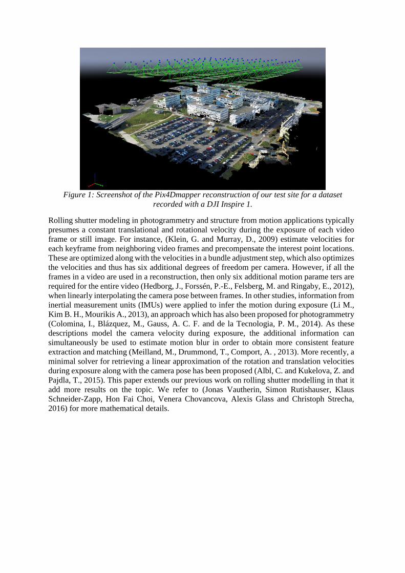
Figure 1: Screenshot of the Pix4Dmapper reconstruction of our test site for a dataset
recorded with a DJI Inspire 1.
Rolling shutter modeling in photogrammetry and structure from motion applications typically
presumes a constant translational and rotational velocity during the exposure of each video
frame or still image. For instance, (Klein, G. and Murray, D., 2009) estimate velocities for
each keyframe from neighboring video frames and precompensate the interest point locations.
These are optimized along with the velocities in a bundle adjustment step, which also optimizes
the velocities and thus has six additional degrees of freedom per camera. However, if all the
frames in a video are used in a reconstruction, then only six additional motion parame ters are
required for the entire video (Hedborg, J., Forssén, P.-E., Felsberg, M. and Ringaby, E., 2012),
when linearly interpolating the camera pose between frames. In other studies, information from
inertial measurement units (IMUs) were applied to infer the motion during exposure (Li M.,
Kim B. H., Mourikis A., 2013), an approach which has also been proposed for photogrammetry
(Colomina, I., Blázquez, M., Gauss, A. C. F. and de la Tecnologia, P. M., 2014). As these
descriptions model the camera velocity during exposure, the additional information can
simultaneously be used to estimate motion blur in order to obtain more consistent feature
extraction and matching (Meilland, M., Drummond, T., Comport, A. , 2013). More recently, a
minimal solver for retrieving a linear approximation of the rotation and translation velocities
during exposure along with the camera pose has been proposed (Albl, C. and Kukelova, Z. and
Pajdla, T., 2015). This paper extends our previous work on rolling shutter modelling in that it
add more results on the topic. We refer to (Jonas Vautherin, Simon Rutishauser, Klaus
Schneider-Zapp, Hon Fai Choi, Venera Chovancova, Alexis Glass and Christoph Strecha,
2016) for more mathematical details.
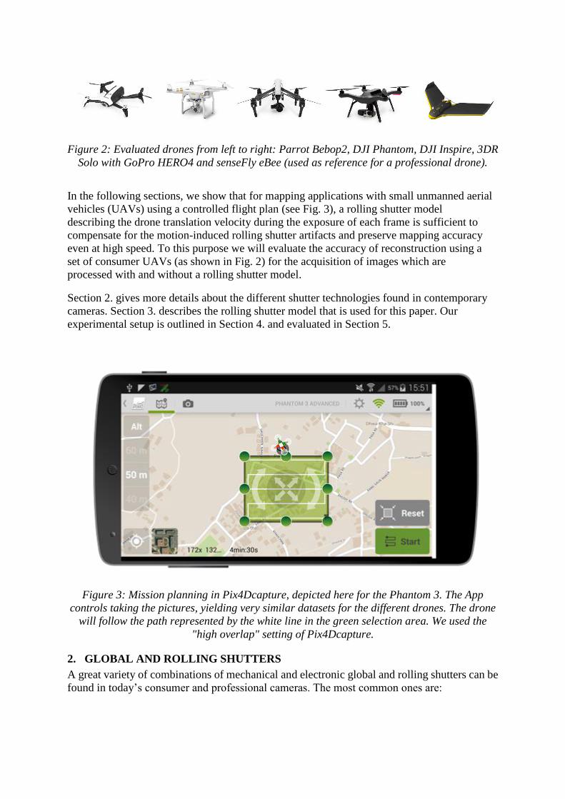
Figure 2: Evaluated drones from left to right: Parrot Bebop2, DJI Phantom, DJI Inspire, 3DR
Solo with GoPro HERO4 and senseFly eBee (used as reference for a professional drone).
In the following sections, we show that for mapping applications with small unmanned aerial
vehicles (UAVs) using a controlled flight plan (see Fig. 3), a rolling shutter model
describing the drone translation velocity during the exposure of each frame is sufficient to
compensate for the motion-induced rolling shutter artifacts and preserve mapping accuracy
even at high speed. To this purpose we will evaluate the accuracy of reconstruction using a
set of consumer UAVs (as shown in Fig. 2) for the acquisition of images which are
processed with and without a rolling shutter model.
Section 2. gives more details about the different shutter technologies found in contemporary
cameras. Section 3. describes the rolling shutter model that is used for this paper. Our
experimental setup is outlined in Section 4. and evaluated in Section 5.
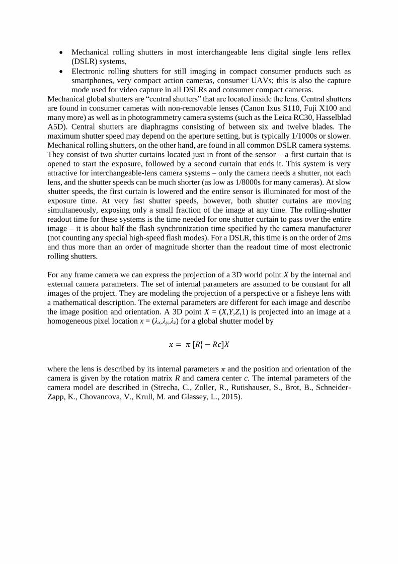
Figure 3: Mission planning in Pix4Dcapture, depicted here for the Phantom 3. The App
controls taking the pictures, yielding very similar datasets for the different drones. The drone
will follow the path represented by the white line in the green selection area. We used the
"high overlap" setting of Pix4Dcapture.
2. GLOBAL AND ROLLING SHUTTERS
A great variety of combinations of mechanical and electronic global and rolling shutters can be
found in today’s consumer and professional cameras. The most common ones are:
Mechanical rolling shutters in most interchangeable lens digital single lens reflex
(DSLR) systems,
Electronic rolling shutters for still imaging in compact consumer products such as
smartphones, very compact action cameras, consumer UAVs; this is also the capture
mode used for video capture in all DSLRs and consumer compact cameras.
Mechanical global shutters are “central shutters” that are located inside the lens. Central shutters
are found in consumer cameras with non-removable lenses (Canon Ixus S110, Fuji X100 and
many more) as well as in photogrammetry camera systems (such as the Leica RC30, Hasselblad
A5D). Central shutters are diaphragms consisting of between six and twelve blades. The
maximum shutter speed may depend on the aperture setting, but is typically 1/1000s or slower.
Mechanical rolling shutters, on the other hand, are found in all common DSLR camera systems.
They consist of two shutter curtains located just in front of the sensor – a first curtain that is
opened to start the exposure, followed by a second curtain that ends it. This system is very
attractive for interchangeable-lens camera systems – only the camera needs a shutter, not each
lens, and the shutter speeds can be much shorter (as low as 1/8000s for many cameras). At slow
shutter speeds, the first curtain is lowered and the entire sensor is illuminated for most of the
exposure time. At very fast shutter speeds, however, both shutter curtains are moving
simultaneously, exposing only a small fraction of the image at any time. The rolling-shutter
readout time for these systems is the time needed for one shutter curtain to pass over the entire
image – it is about half the flash synchronization time specified by the camera manufacturer
(not counting any special high-speed flash modes). For a DSLR, this time is on the order of 2ms
and thus more than an order of magnitude shorter than the readout time of most electronic
rolling shutters.
For any frame camera we can express the projection of a 3D world point X by the internal and
external camera parameters. The set of internal parameters are assumed to be constant for all
images of the project. They are modeling the projection of a perspective or a fisheye lens with
a mathematical description. The external parameters are different for each image and describe
the image position and orientation. A 3D point X = (X,Y,Z,1) is projected into an image at a
homogeneous pixel location x = (λx,λy,λz) for a global shutter model by
𝑥 = 𝜋 [𝑅¦ − 𝑅𝑐]𝑋
where the lens is described by its internal parameters π and the position and orientation of the
camera is given by the rotation matrix R and camera center c. The internal parameters of the
camera model are described in (Strecha, C., Zoller, R., Rutishauser, S., Brot, B., Schneider-
Zapp, K., Chovancova, V., Krull, M. and Glassey, L., 2015).
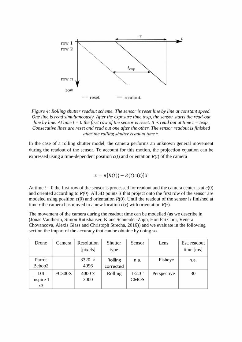
Figure 4: Rolling shutter readout scheme. The sensor is reset line by line at constant speed.
One line is read simultaneously. After the exposure time texp, the sensor starts the read-out
line by line. At time t = 0 the first row of the sensor is reset. It is read out at time t = texp.
Consecutive lines are reset and read out one after the other. The sensor readout is finished
after the rolling shutter readout time τ.
In the case of a rolling shutter model, the camera performs an unknown general movement
during the readout of the sensor. To account for this motion, the projection equation can be
expressed using a time-dependent position c(t) and orientation R(t) of the camera
𝑥 = 𝜋[𝑅(𝑡)¦ − 𝑅(𝑡)𝑐(𝑡)]𝑋
At time t = 0 the first row of the sensor is processed for readout and the camera center is at c(0)
and oriented according to R(0). All 3D points X that project onto the first row of the sensor are
modeled using position c(0) and orientation R(0). Until the readout of the sensor is finished at
time τ the camera has moved to a new location c(τ) with orientation R(τ).
The movement of the camera during the readout time can be modelled (as we describe in
(Jonas Vautherin, Simon Rutishauser, Klaus Schneider-Zapp, Hon Fai Choi, Venera
Chovancova, Alexis Glass and Christoph Strecha, 2016)) and we evaluate in the following
section the impart of the accuracy that can be obtaine by doing so.
Drone Camera Resolution Shutter Sensor Lens Est. readout
[pixels] type time [ms]
Parrot
Bebop2
3320 ×
4096
Rolling
corrected
n.a. Fisheye n.a.
DJI
Inspire 1
x3
FC300X 4000 ×
3000
Rolling 1/2.3”
CMOS
Perspective 30
DJI
Inspire 1
X5
FC300X 4608 ×
3456
Rolling 1/2.3”
CMOS
Perspective 30
Phantom
3
FC200 4000 ×
3000
Rolling 1/2.7”
CMOS
Perspective 30
Table 1: Specifications of the evaluated cameras and their estimated readout time. The field of
view denotes the horizontal/vertical field of view as we measure it. The FC300X has a 20mm
lens and the Canon S110 has a zoom lens set to 24mm (both in 35mm format equivalent). The
readout time estimations coming from our model have been confirmed by DJI for the FC200
and FC300X cameras.
3. EXPERIMENTS
For all elevuated drones we used Pix4Dcapture, an app that is managing the drone flight to
cover the area of interest and to capture images in a regular way - optimal for building maps.
Pix4Dcapture is a free app available on android and IOS. The workflow is easy and as follows:
Open the app and select the consumer drone
Select the area to map (as shown in green below
Start the mission (the drone will automatically fly the optimal flight plan that covers the
selected area and takes pictures
After the last picture the drone will automatically fly to its home point and land
The images are transferred to the phone and are put into Pix4Dmapper to process
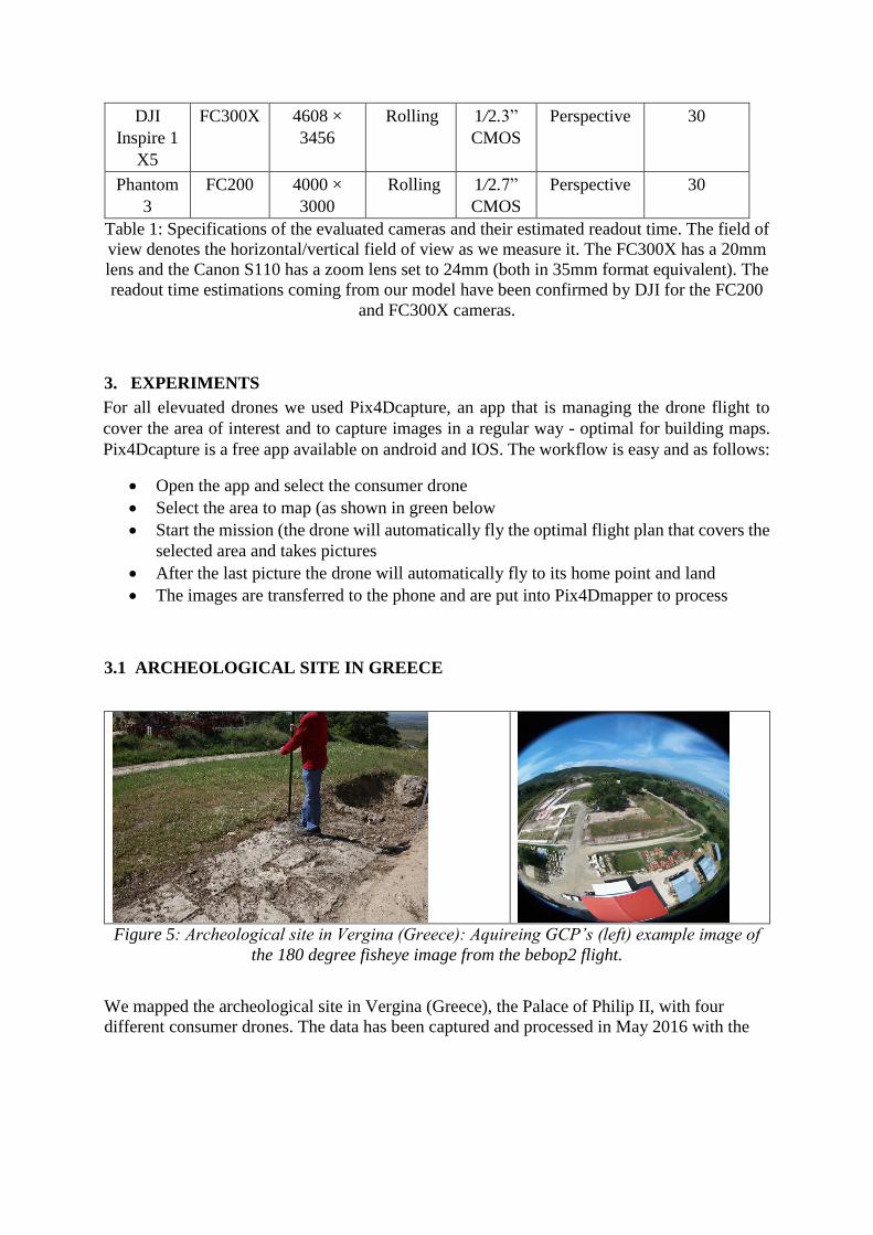
3.1 ARCHEOLOGICAL SITE IN GREECE
Figure 5: Archeological site in Vergina (Greece): Aquireing GCP’s (left) example image of
the 180 degree fisheye image from the bebop2 flight.
We mapped the archeological site in Vergina (Greece), the Palace of Philip II, with four
different consumer drones. The data has been captured and processed in May 2016 with the
Bebop2, Inspire 1 with x3 and x5 gimbal and the Phantom 3 professional (see Table 1 and
Figure 5). Five GCP’s have been aquired and 20 validation points.
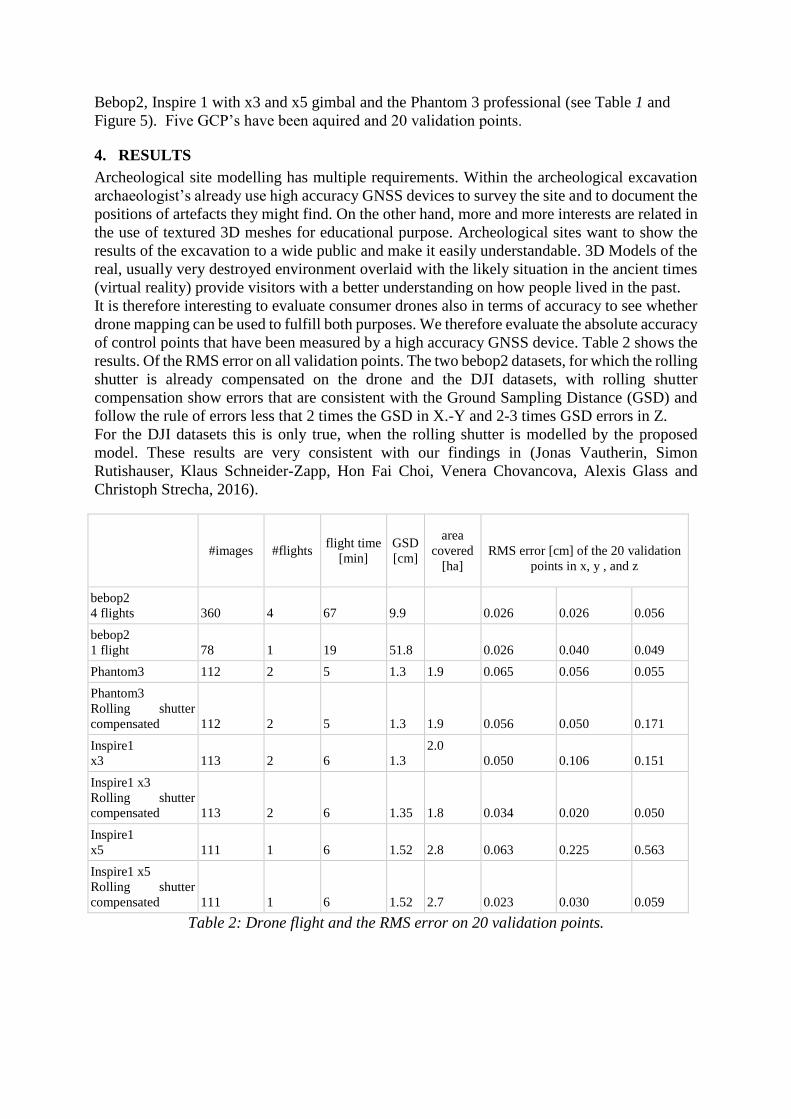
4. RESULTS
Archeological site modelling has multiple requirements. Within the archeological excavation
archaeologist’s already use high accuracy GNSS devices to survey the site and to document the
positions of artefacts they might find. On the other hand, more and more interests are related in
the use of textured 3D meshes for educational purpose. Archeological sites want to show the
results of the excavation to a wide public and make it easily understandable. 3D Models of the
real, usually very destroyed environment overlaid with the likely situation in the ancient times
(virtual reality) provide visitors with a better understanding on how people lived in the past.
It is therefore interesting to evaluate consumer drones also in terms of accuracy to see whether
drone mapping can be used to fulfill both purposes. We therefore evaluate the absolute accuracy
of control points that have been measured by a high accuracy GNSS device. Table 2 shows the
results. Of the RMS error on all validation points. The two bebop2 datasets, for which the rolling
shutter is already compensated on the drone and the DJI datasets, with rolling shutter
compensation show errors that are consistent with the Ground Sampling Distance (GSD) and
follow the rule of errors less that 2 times the GSD in X.-Y and 2-3 times GSD errors in Z.
For the DJI datasets this is only true, when the rolling shutter is modelled by the proposed
model. These results are very consistent with our findings in (Jonas Vautherin, Simon
Rutishauser, Klaus Schneider-Zapp, Hon Fai Choi, Venera Chovancova, Alexis Glass and
Christoph Strecha, 2016).
#images #flights flight time
[min]
GSD
[cm]
area
covered
[ha]
RMS error [cm] of the 20 validation
points in x, y , and z
bebop2
4 flights 360 4 67 9.9 0.026 0.026 0.056
bebop2
1 flight 78 1 19 51.8 0.026 0.040 0.049
Phantom3 112 2 5 1.3 1.9 0.065 0.056 0.055
Phantom3
Rolling shutter
compensated 112 2 5 1.3 1.9 0.056 0.050 0.171
Inspire1
x3 113 2 6 1.3
2.0
0.050 0.106 0.151
Inspire1 x3
Rolling shutter
compensated 113 2 6 1.35 1.8 0.034 0.020 0.050
Inspire1
x5 111 1 6 1.52 2.8 0.063 0.225 0.563
Inspire1 x5
Rolling shutter
compensated 111 1 6 1.52 2.7 0.023 0.030 0.059
Table 2: Drone flight and the RMS error on 20 validation points.
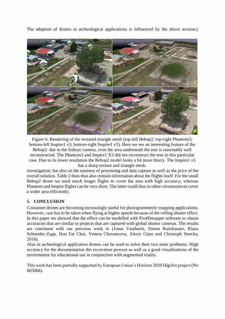
The adaption of drones in archeological applications is influenced by the above accuracy
investigation, but also on the easiness of processing and data capture as well as the price of the
overall solution. Table 2 does thus also contain information about the flights itself. For the small
Bebop2 drone we need much longer flights to cover the area with high accuracy, whereas
Phantom and Inspire flights can be very short. The latter could thus in other circumstances cover
a wider area efficiently.
5. CONCLUSION
Consumer drones are becoming increasingly useful for photogrammetric mapping applications.
However, care has to be taken when flying at higher speeds because of the rolling shutter effect.
In this paper we showed that the effect can be modelled with Pix4Dmapper software to obtain
accuracies that are similar to projects that are captured with global shutter cameras. The results
are consistent with our previous work in (Jonas Vautherin, Simon Rutishauser, Klaus
Schneider-Zapp, Hon Fai Choi, Venera Chovancova, Alexis Glass and Christoph Strecha,
2016).
Also in archeological application drones can be used to solve their two main problems: High
accuracy for the documentation the excavation process as well as a good visualizations of the
environment for educational use in conjunction with augmented reality.
This work has been partially supported by European Union’s Horizon 2020 DigiArt project (No
665066).
Figure 6: Rendering of the textured triangle mesh (top-left Bebop2; top-right Phantom3;
bottom-left Inspire1 x3; bottom-right Inspire1 x5). Here we see an interesting feature of the
Bebop2: due to the fisheye camera, even the area underneath the tree is reasonably well
reconstructed. The Phantom3 and Inspire1 X3 did not reconstruct the tree in this particular
case. Due to its lower resolution the Bebop2 model looks a bit more blurry. The Inspire1 x5
has a sharp texture and triangle mesh.
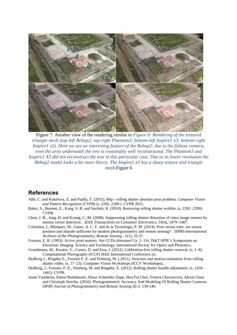
Figure 7: Another view of the rendering similar to Figure 6: Rendering of the textured
triangle mesh (top-left Bebop2; top-right Phantom3; bottom-left Inspire1 x3; bottom-right
Inspire1 x5). Here we see an interesting feature of the Bebop2: due to the fisheye camera,
even the area underneath the tree is reasonably well reconstructed. The Phantom3 and
Inspire1 X3 did not reconstruct the tree in this particular case. Due to its lower resolution the
Bebop2 model looks a bit more blurry. The Inspire1 x5 has a sharp texture and triangle
mesh.Figure 6
References Albl, C. and Kukelova, Z. and Pajdla, T. (2015). R6p - rolling shutter absolute pose problem. Computer Vision
and Pattern Recognition (CVPR) (s. 2292–2300.). CVPR 2015. Baker, S., Bennett, E., Kang, S. B. and Szeliski, R. (2010). Removing rolling shutter wobble. (s. 2392–2399).
CVPR.
Chun, J.-B., Jung, H. and Kyung, C.-M. (2008). Suppressing rolling-shutter distortion of cmos image sensors by
motion vector detection. . IEEE Transactions on Consumer Electronics, 54(4), 1479–1487.
Colomina, I., Blázquez, M., Gauss, A. C. F. and de la Tecnologia, P. M. (2014). Pose versus state: are sensor
position and attitude sufficient for modern photogrammetry and remote sensing? . ISPRS-International
Archives of the Photogrammetry, Remote Sensing , 1(1), 33-37.
Fossum, E. R. (1993). Active pixel sensors: Are CCDs dinosaurs? (s. 2–14). IS&T/SPIE’s Symposium on
Electronic Imaging: Science and Technology, International Society for Optics and Photonics.
Grundmann, M., Kwatra, V., Castro, D. and Essa, I. (2012). Calibration-free rolling shutter removal. (s. 1–8).
Computational Photography (ICCP) IEEE International Conference on.
Hedborg J., Ringaby E., Forssén P.-E. and Felsberg, M. (.2011). Structure and motion estimation from rolling
shutter video. (s. 17–23). Computer Vision Workshops (ICCV Workshops),.
Hedborg, J., Forssén, P.-E., Felsberg, M. and Ringaby, E. (2012). Rolling shutter bundle adjustment. (s. 1434–
1441). CVPR.
Jonas Vautherin, Simon Rutishauser, Klaus Schneider-Zapp, Hon Fai Choi, Venera Chovancova, Alexis Glass
and Christoph Strecha. (2016). Photogrammetric Accuracy And Modeling Of Rolling Shutter Cameras.
ISPRS Journal of Photogrammetry and Remote Sensing III-3, 139-146.

Klein, G. and Murray, D. (2009). Parallel tracking and mapping on a camera phone. In: Mixed and Augmented
Reality IEEE, pp. (s. 83–86). ISMAR.
Li M., Kim B. H., Mourikis A. (2013). Real-time motion tracking on a cellphone using inertial sensing and a
rollingshutter camera. (s. 4712–4719). Robotics and Automation (ICRA).
Liang, C.-K., Chang, L.-W. and Chen, H. H. (2008). Analysis and compensation of rolling shutter effect. Image
Processing, IEEE Transactions, 17(8), 1323–1330.
Litwiller, D. (2001). CCD vs. CMOS: Facts and fiction. Photonics Spectra.
Magerand, L. and Bartoli, A. (2010). A generic rolling shutter camera model and its application to dynamic pose
estimation. International symposium on 3D data processing, visualization and transmission.
Meilland, M., Drummond, T., Comport, A. . (2013). A unified rolling shutter and motion blur model for 3d
visual registration. (s. 2016–2023). Computer Vision (ICCV).
Nakamura. (2015). Image sensors and signal processing for digital still cameras. CRC Press.
Strecha, C., Zoller, R., Rutishauser, S., Brot, B., Schneider-Zapp, K., Chovancova, V., Krull, M. and Glassey, L.
(2015). Quality assesment of 3d reconstruction using fisheye and perspective sensors. ISPRS Annals of
the Photogrammetry, Remote Sensing and Spatial Information Sciences , II-3(W4), 215-22.