1997- Simplified concepts in spectroscopy and photochemistry
PHOTOCHEMISTRY & SPECTROSCOPY 3.1
UNIT III
PHOTOCHEMISTRY
AND SPECTROSCOPY
PHOTOCHEMISTRY
3.1 INTRODUCTION
Photochemistry is the study of chemical reactions resulting from the exposure
of light radiations. The radiations of visible and ultraviolet portion spectrum ranging
from 2,000 - 8,000 Å. Wavelength are mainly of concern in photochemical reaction.
3.2 PHOTOCHEMICAL REACTIONS
All photochemical reactions take place in two stages. In the primary process,
the reacting molecules undergo activation by absorption of light. This is followed
by t he seco ndary pr o cess, in which t he act ivat ed mo lecules undergo a
photochemical charge.
Example: Combination of hydrogen and chlorine, the primary process is
Cl2 h 2Cl*
The activated chlorine atoms Cl*
undergoes chemical reaction as
*
This is a secondary process.
H2
+ Cl HCl + H

3.2 Engineering Chemistry-I
6 14 2 6 11
2 2
28 20
(i) Dark reactions
The chemical reactions, which take place in the absence of light are called
dark reactions.
(ii) Thermal reactions
Chemical reactions, which takes place by the absorption of heat are called
thermal reactions.
3.2.1 Classification of photochemical reactions
(i) Dissociation reactions
Example:
2HI
h H I
(g) 2( g) 2(g)
h
2HBr(g)
H2(g)
+ Br2(g)
(ii) Double decomposition reactions
Example : C H Br h C H Br HBr
(iii) Rearrangement reactions
2053Å
Maleic acid
(iv) Addition reactions
Example : CO Cl h COCl
(v) Polymerisation reactions
Example :
2(C14 H10 ) h C H
Anthracene Dianthracene
(vi) Chain reactions
Example : h
H2 Cl2 2HCl

PHOTOCHEMISTRY & SPECTROSCOPY 3.3
3.3 LAWS OF PHOTOCHEMISTRY
3.3.1 Grotthus-Draper law (or) The principle of
photochemical activation
It also referred to as the first law of photochemistry. This law states that “only
light which is absorbed can be effective in producing a chemical change.”
This law has a certain limitation. It has been found experimentally that a
light of particular wavelength is responsible for the photochemical change. This
light is called the effective light of the photochemical change.
Example: When white light is passed through, alkaline solution of cupric
tartarate, the dissolved substance undergoes photo chemical reduction to cuprous
oxide.
Absorption spectrum measurements show that infrared and ultraviolet are also
absorbed by the solution, but ultraviolet light only covering a small range of
wavelengths brings about the photochemical reduction. Hence, the ultraviolet light
is the effective light for this photochemical change.
3.3.2 Stark-Einstein law
It states that in the primary process, each reacting molecule is activated by
one quantum of effective light. Hence the law implies a 1:1 relationship between
the number of reacting molecules and the number of quanta of light absorbed. It
is applicable only to the primary process.
Explanation
A A B C
Reactant
molecule Excited
molecule
Product
molecule-1
Product
molecule-2
Fig. 3.1 Illustration of law of photochemical equivalence
3.4 Engineering Chemistry-I
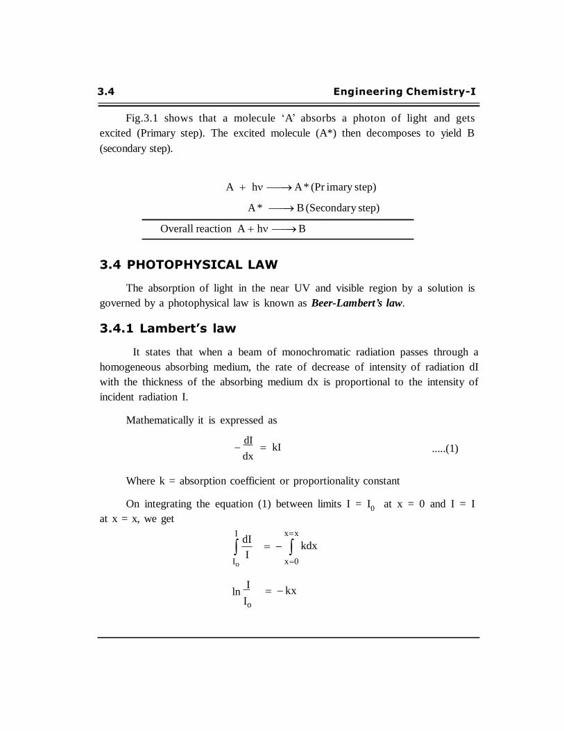
Fig.3.1 shows that a molecule ‘A’ absorbs a photon of light and gets
excited (Primary step). The excited molecule (A*) then decomposes to yield B
(secondary step).
A h A * (Pr imary step)
A * B (Secondary step)
Overall reaction A h B
3.4 PHOTOPHYSICAL LAW
The absorption of light in the near UV and visible region by a solution is
governed by a photophysical law is known as Beer-Lambert’s law.
3.4.1 Lambert’s law
It states that when a beam of monochromatic radiation passes through a
homogeneous absorbing medium, the rate of decrease of intensity of radiation dI
with the thickness of the absorbing medium dx is proportional to the intensity of
incident radiation I.
Mathematically it is expressed as
dI dx
kI
.....(1)
Where k = absorption coefficient or proportionality constant
On integrating the equation (1) between limits I = I0
at x = 0 and I = I
at x = x, we get
I dI
I Io
xx
x 0
kdx
ln I
Io
kx

PHOTOCHEMISTRY & SPECTROSCOPY 3.5
I
Io
ekx
I Ioe kx .....(2)
This equation is known as Lambert’s law.
3.4.2 Beer’s law (or) Beer Lambert’s law
This law states that when a beam of monochromatic radiation passes
through a solution of an absorbing substance, the rate of decrease of intensity of
radiation dI with the thickness of the absorbing solution dx is proportional to
the intensity of the incident radiation I as well as the concentration of the
solution C
Mathematically, it is expressed as
dI dx
kI c .....(3)
Where k = Molar absorption coefficient.
On integrating the equation (3) between limits I = I0 at x = 0 and I = I at
x = x, we get
I dI
I Io
x
= k C d x 0
ln I
Io
ln I
Io
= kCx
= – kCx
By taking natural logarithm
2.303 log I
Io
= kCx
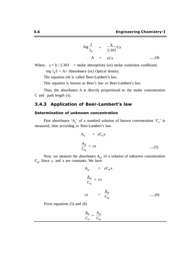
3.6 Engineering Chemistry-I
log I
Io =
k Cx
2.303
A = Cx
.....(4)
Where, = k / 2.303 = molar absorptivity (or) molar extinction coefficient.
log I 0/I = A= Absorbance (or) Optical density.
The equation (4) is called Beer-Lambert’s law.
This equation is known as Beer’s law or Beer-Lambert’s law.
Thus, the absorbance A is directly proportional to the molar concentration
C and path length (x).
3.4.3 Application of Beer-Lambert’s law
Determination of unknown concentration
First absorbance ‘As’ of a standard solution of known concentration ‘C
s’ is
measured, then according to Beer-Lambert’s law.
AS
= Cs x
AS x CS
....(5)
Now, we measure the absorbance Au, of a solution of unknown concentration Cu, Since and x are constants. We have
Au =
Cu x
A u
Cu
x
From equations (5) and (6)
As
Cs
x
=
A u
Cu
A u
Cu
.....(6)

PHOTOCHEMISTRY & SPECTROSCOPY 3.7
C
u =
Au Cs
As
.....(7)
Since the values of Au
and As
are experimentally determined values and Cs
is known, the value of unknown concentration Cu
can be calculated from the
equation (7).
3.4.4 Limitations of Beer-Lambert’s law
If the solution contains impurities, deviation may occur.
If the solution undergoes polymerization, deviation also occurs
It is applicable for dilute solutions
It is not obeyed if the radiation used is not monochromatic.
It is not applied to suspensions.
PROBLEM 1 :
Find out the absorbance (or) optical density of a solution, if the
transmittance of a solution is 16.4%
Given :
Percentage (%) of transmittance (% T) = 16.4% (or)
16.4 0.164
Transmittance (T) =
100
Solution :
Absorbance (or) Optical Density A =
log 1
(or) log T T
= – log 0.164
= –(– 0.785)
Absorbance (or) Optical density A = 0.785
3.8 Engineering Chemistry-I
Absorbance A = – log T
= – log 0.186
= – (– 0.730)
A = 0.730
PROBLEM 2 :
The percentage transmittance of 5×10⁻⁴
M solution of disodium fumarate
in a 1 cm c ell is 1 8. 6% . Ca lcu l ate ( i) th e abso rban ce ( A)
(ii) the molar absorption coefficient ( )
Given :
% T = 18.6% (or)
T
C
=
=
0.186
5×10⁻⁴
M
x = 1 cm
Solution :
(i)
(ii)The molar absorption coefficient
We know that A =
Cx
A
Cx
0 .7 3 0 =
5 1 0 4
1
= 1.46 × 10³
dm3
mol–1
cm–1
PROBLEM 3 :
The percentage transmittance of 5×10⁻⁴
m solution of disodium fumarate
in a 1 cm cell is 17.8%. Calculate
(i) the absorbance (A)
(ii) the molar absorption coefficient ( )

PHOTOCHEMISTRY & SPECTROSCOPY 3.9
Given :
Solution :
% T = 17.8%
(or) T = 0.178
C = 5×10⁻⁴
M
x = 1 cm
Absorbance A = – log T
= – log 0.178
= – (– 0.750)
A = 0.750
(ii)The molar absorption coefficient
A
We know that Cx
A Cx
0 .7 5 0 =
5 1 0 4
1
= 1.5 × 10³
dm3
mol–1
cm–1
PROBLEM 4 :
Calculate the molar absorption of a solution 1×10⁻⁴
M. The absorbance
of which is 0.24, when the path length is 2.0 cm.
Given : A = 0.24
C = 1 × 10– 4
M
x = 2.0 cm
Solution :
We know that
A
Cx
A Cx
0 .2 4 =
1 1 0 4
2
= 1.2 × 10³
dm3
mol–1
cm–1

3.10 Engineering Chemistry-I
% T = 40%
(or) T = 0.40
x
=
=
2.0 cm
6,000 dm3
mol–1
PROBLEM 5 :
A solution shows a transm ittance of 20% when taken in a cell of
2.5 cm thickness. Calculate its concentration of the molar absorption coefficient
is 12,000 dm3
mol–1
cm–1
. (AU. Jan.2005)
Given :
Solution :
% T = 20%
(or) T = 0.20
x = 2.5 cm
= 12,000 dm3
mol–1
cm–1
Absorbance A = – log T
= – log 0.20
A = 0.699
We know that
A
Cx
0.699
A Cx
= 12000 2.5
= 2.33 × 10⁻⁵
mol dm–3
PROBLEM 6 :
A solution of thickness 2cm transmits 40% incident light. Calculate the
con cen t rati on o f th e so lu ti on g iven th e = 60 00 d m3
mo l–1
cm – 1
(TAU. June 2010)
Given :
cm–1

PHOTOCHEMISTRY & SPECTROSCOPY 3.11
Solution :
Absorbance A = – log T
= – log 0.40
= – (–0.398)
A = 0.398
C A
We know that x A Cx
0.398 =
6000 2
C = 3.316 × 10⁻⁵
mol dm–3
PROBLEM 7 :
A m on och rom atic radiation is in ciden t on a solution of 0.05 M
concentration of an absorbing substance. The intensity of the radiation is reduced
to one-forth of the initial value after passing through 10 cm length of the
solu tion. Calculate the m olar extinction co- efficient of the substance.
(AU, B.Tech, May 2003)
Given :
C = 0.05 M
x = 10 cm
I = 1/4
I = 1
Solution :
According to Beer-Lambert’s law
log I
Io
Cx
This equation may be written as
=
log I
Cx I o
3.12 Engineering Chemistry-I
= log 1 / 4
1
= log 0.25
0.5
0.05 10
= (0.6020)
0.5
= 1.204
Molar extinction co-efficient = 1.204 dm3
mol–1
cm–1
3.5 QUANTUM EFFICIENCY ()
The number of moles of the substance undergoing photochemical change per
Einstein of radiation absorbed is known as quantum efficiency.
Alternatively, it is the number of molecules of the substance undergoing
photochemical change per quantum of radiation absorbed.
Thus, No. of molecules reacting in a given time
No. of quanta of light absorbed in the same time
If we measure the rate of formation of product, then quantum yield can be
written as,
d[Pr oduct] / dt
Number of quanta absorbed
d[Pr oduct] / dt
Iabs
Where, Iabs
= Number of quanta absorbed.

PHOTOCHEMISTRY & SPECTROSCOPY 3.13
3.5.1 Low or high quantum yield
The quantum efficiency varies from zero to 106. If a reaction obeys the
Einstein law, one molecule is decomposed per photon, the quantum yield
1 .
(i) Low quantum yield
When the number of molecules decomposed is less than one per photon, the
quantum yield 1 and the reaction has a low quantum yield.
(ii) High quantum yield
1
When two or more molecules are decomposed per photon, the quantum yield
and the reaction has a high quantum yield.
3.5.2 Conditions for high and low quantum yield
All the reactant molecules should be initially in the same energy state and
hence equally reactive.
Molecules in the activated state should be largely unstable and decompose
to form the products.
The reactivity of the molecules should be temperature independent.
3.5.3 Causes (or) Reasons for low quantum yield
Excited molecules may get deactivated before they form products.
Excited molecules may lose their energy by collisions with non-excited
molecules.
Molecules may receive insufficient energy thereby reaction does not occur.
Reversion of the primary photochemical reaction.
Recombination of fragments (obtain by dissociation) will give low
quantum yield.
3.14 Engineering Chemistry-I
Example:
(i) Dimerization of anthracene to dianthracene
2C14 H 10 h C28H20
Quantum yield = 2, Actually it is found to be 0.5.
Because, the above reaction is reversible
2C14 H 10 h
thermal
C28H20
3.5.4 Causes (or) Reason for high quantum yield
Absorption of radiation produces atoms or free radicals, which initiate a series
of chain reactions.
Formation of an intermediate product, which acts as a catalyst.
If the reaction is exothermic the heat evolved may activate other molecules,
without absorption of additional quanta of radiation.
The active molecules produced by primary absorption may collide with other
molecules and activate them which inturn activate other reacting molecules.
Example:
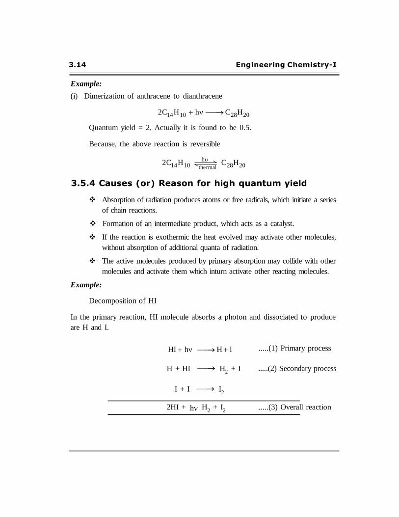
Decomposition of HI
In the primary reaction, HI molecule absorbs a photon and dissociated to produce
are H and I.
HI h H I .....(1) Primary process
H + HI H2
+ I .....(2) Secondary process
I + I I2
2HI + h H2
+ I2
.....(3) Overall reaction
PHOTOCHEMISTRY & SPECTROSCOPY 3.15
In the secondary reaction, step(1) H react with HI to produce H2
and I. This I
react with step(1) I to produce I2.
T he o ve r all r eact io n sho ws t hat t he t wo HI a r e de co mpo sed fo r
one photon ( h ). so the quantum yield () =2.
3.6 DETERMINATION OF QUANTUM EFFICIENCY (OR)
QUANTUM YIELD
Quantum yield, of a photochemical reaction is expressed as
Number of molecules reacted (or) formed
Number of photons (or) Quanta of radiation absorbed
(or)
Number of moles reacted (or) formed
Number of Einsteins of radiation absorbed
We can calculate the quantum yield from the determination of the following:
(i) Determination of the number of molecules reacted in a given time.
(ii) Determination of the amount of photons absorbed in the same time.
3.6.1 Experimental determination of number of
molecules reacted
The number of molecules reacted in a given time can be determined by the
usual analytical techniques used in chemical kinetics.
The rate of reaction is measured by the usual methods. Small quantities of
the samples are pipetted out from the reaction mixture from time to time and the
concentration of the reactants are continuously measured by the volumetric methods
(or) optical rotation (or) absorption.
From the data, the amount and number of molecules can be calculated.
3.16 Engineering Chemistry-I
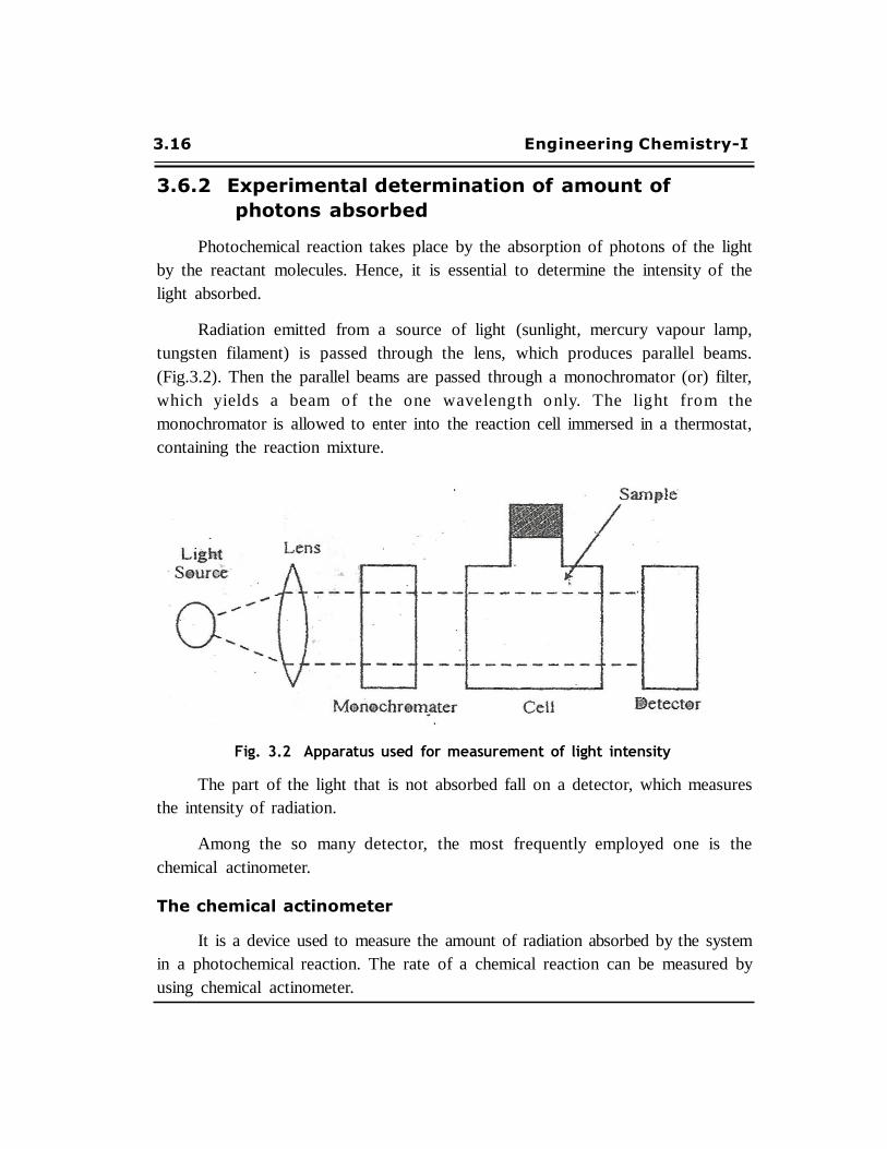
Fig. 3.2 Apparatus used for measurement of light intensity
3.6.2 Experimental determination of amount of
photons absorbed
Photochemical reaction takes place by the absorption of photons of the light
by the reactant molecules. Hence, it is essential to determine the intensity of the
light absorbed.
Radiation emitted from a source of light (sunlight, mercury vapour lamp,
tungsten filament) is passed through the lens, which produces parallel beams.
(Fig.3.2). Then the parallel beams are passed through a monochromator (or) filter,
which yield s a beam o f t he o ne wave leng t h o nly. T he lig ht fr o m t he
monochromator is allowed to enter into the reaction cell immersed in a thermostat,
containing the reaction mixture.
The part of the light that is not absorbed fall on a detector, which measures
the intensity of radiation.
Among the so many detector, the most frequently employed one is the
chemical actinometer.
The chemical actinometer
It is a device used to measure the amount of radiation absorbed by the system
in a photochemical reaction. The rate of a chemical reaction can be measured by
using chemical actinometer.

PHOTOCHEMISTRY & SPECTROSCOPY 3.17
2 2
2
Uranyl oxalate actinometer
The most commonly used chemical actinometer is uranyl oxalate actinometer.
It contains 0.05 M oxalic acid and 0.01 M Uranyl sulphate in water.
When it is exposed to radiation, oxalic acid undergoes decomposition to give
H2O, CO and CO
2
UO2
h UO2 *
UO2 *
+ COOH
COOH
2+
UO + CO + CO + H O
2 2 2
The residual concentration of oxalic acid can be calculated by titrating with
standard KMnO4. The amount of oxalic acid consumed is a measure of the
intensity of radiation.
Calculation of the amount of radiation absorbed.
Step-1 : The empty cell (or) the cell filled with solvent is exposed to raidation
and reading is noted = Total incident energy.
Step-2 : The cell is filled with the reactants and again the reading is noted
= Residual energy.
Total Residual
Total energy absorbed by the reacting mixture = incident energy energy transmitted
3.7 PHOTOPHYSICAL PROCESS
Generally atoms or molecules goes to excited state by the absorption of
suitable radiation. When the absorbed radiation is not used to cause chemical
reaction, it will be re-emitted as light of longer wavelength.

3.18 Engineering Chemistry-I
3.7.1 Types of photophysical process
There are two types of process:
(i) Fluorescence
(ii) Phosphorescence
(i) Fluorescence
When a molecule or atom absorbs radiation of short wavelength (high
frequency) it gets excited. Then the excited atom (or) molecule re-emits the
radiation of the same frequency (or) lower frequency within short time about 10–8
sec. Fluorescence stops as soon as the incident radiation is cut off. This process
is called fluorescence.
The substance which exhibits fluorescence is called fluorescent substance.
Examples: Calcium fluoride (CaF2), Uranium, Petroleum, iodine, mercury,
organic dyestaff (fluorescein), etc.
Uses
Fluorescent dyes are used in paints and fabrics to make them glow, when
bombarded with ultraviolet photons in sunlight.
(ii) Phosphorescence
When a molecule or atom absorbs radiation of higher frequency, the emission
of radiation is continuous for sometime, even when the incident radiation is cut
off. This process is called phosphorescence (or) delayed fluorescence.
The substance which exhibits phosphorescence is called phosphorescent
substance.
Examples: Zinc sulphide, alkaline earth sulphides (CaS, BaS and SrS).
Applications
Phosphorescent materials are used in luminous clock dials and in other
objects that are made to glow in the dark.
PHOTOCHEMISTRY & SPECTROSCOPY 3.19
3.7.2 Difference between phosphorescence and
fluorescence
Photophorescence Fluorescence
Decay period is very short.
i.e., 10–9
to 10–4
S.
Decay period is much longer.
i.e., 10–4
to 100 s.
It can be observed in solution
at room temperature.
It is not observed in solution
at room temperature.
It is the radiation emitted in a
transition between states at
same multiplicity.
It is the radiation emitted in a
transition between states of different
multiplicity.
Its spectrum is not mirror image
of the absorption spectrum.
Its spectrum is mirror image of
the absorption spectrum.
Example: Zinc sulphide,
Sulphides of alkaline earth-metals.
Example: CaF2, Petroleum, Uranium.
3.7.3 Mechanism of photophysical process (or)
Jablonski diagram
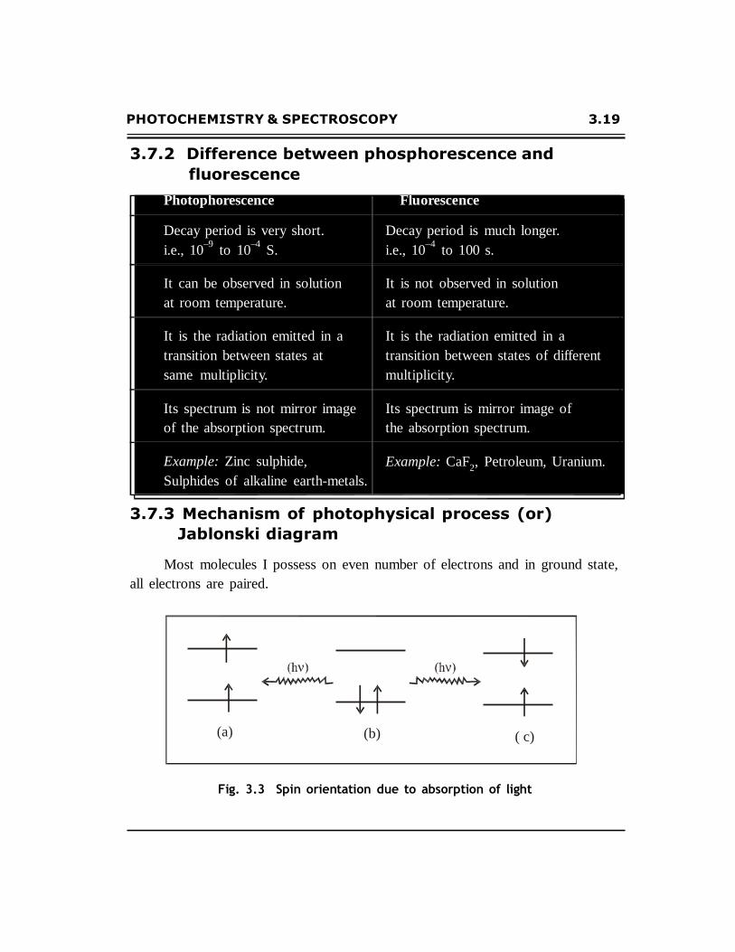
Most molecules I possess on even number of electrons and in ground state,
all electrons are paired.
(a) (b)
( c)
Fig. 3.3 Spin orientation due to absorption of light
3.20 Engineering Chemistry-I
(i) Spin multiplicity
The term 2S+1 is known as spin multiplicity.
Where, S is the total electronic spin.
(ii) Singlet ground state
When the spins are paired ( ) [Fig. 3.3(a)], the clockwise orientation of
one electron is cancelled by the anticlockwise orientation of other electron.
Thus, S = s1
+ s2
1
1 0
=
2 2
2S + 1 = 2 (0) + 1
= 0 + 1 = 1
i.e., spin multiplicity of the molecule = 1
The molecule is in the singlet ground state.
(iii) Triplet excited state
On absorption of a photon of energy, h , one of the paired electrons goes
to a higher energy level (i.e. excited state), the spin orientations of the two electrons
may be either
(a) Parallel () [Fig.3.3(b)]
Then, S = s1
+ s2
= 1
1 1
2 2
2S + 1 = 2 (1) + 1
= 2 + 1 = 3
i.e., spin multiplicity of the molecule = 3
The molecule is in the triplet excited state.
PHOTOCHEMISTRY & SPECTROSCOPY 3.21
(iv) Singlet excited state
(b) Anti parallel () Fig. 3.3. (c)
Then, S = s1
+ s2
1
1 0
=
2 2
2S + 1 = 2 (0) + 1
= 0 + 1 = 1
i.e., spin multiplicity of the molecule = 1
The molecule is in the singlet excited state.
Mechanism on explanation
Depending upon the energy h of the photon, electron can jump to any
higher electronic state. So we get the series of
(i) Singlet excited states S1, S
2, S
3.... etc.
(ii) Triplet excited state T1, T
2, T
3 ... etc.
(a) S1, S
2, S
3, ... etc. are called first singlet excited state, second singlet
excited state, third singlet excited state, etc. respectively.
(b) T1, T
2, T
3, ... etc. are called first triplet excited state, second triplet
excited state, third triplet excited state, etc. respectively.
Generally singlet excited state has higher energy than the corresponding
triplet excited state. Thus,
E(S1) > E (T
1) ; E(S
2) > E (T
2) ; E(S
3) > E (T
3) and so on.
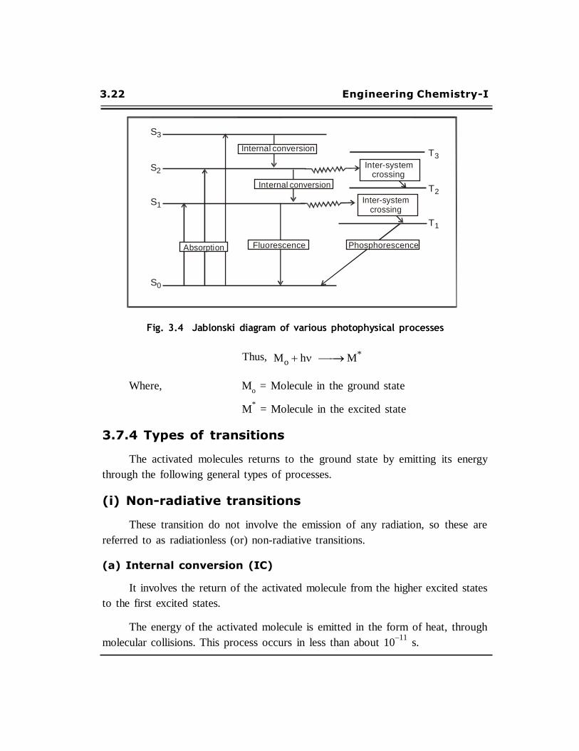
When a molecule absorbs light radiation, the electron may jump from So
to S1,
S2
(or) S3
singlet excited state depending upon energy of the light radiation as shown
in Jablonski diagram (Fig. 3.4). For each singlet excited state there is a corresponding
triplet excited state.
3.22 Engineering Chemistry-I
S3
Internal conversion T3
S2 Inter-system
crossing
Internal conversion
S1
T2
Inter-system crossing
T1
Absorption Fluorescence Phosphorescence
S0
Fig. 3.4 Jablonski diagram of various photophysical processes
Thus, Mo h M*
Where, Mo
= Molecule in the ground state
M*
= Molecule in the excited state
3.7.4 Types of transitions
The activated molecules returns to the ground state by emitting its energy
through the following general types of processes.
(i) Non-radiative transitions
These transition do not involve the emission of any radiation, so these are
referred to as radiationless (or) non-radiative transitions.
(a) Internal conversion (IC)
It involves the return of the activated molecule from the higher excited states
to the first excited states.
The energy of the activated molecule is emitted in the form of heat, through
molecular collisions. This process occurs in less than about 10–11
s.

PHOTOCHEMISTRY & SPECTROSCOPY 3.23
S3 S1
S2 S1
(b) Intersystem crossing (ISc)
The energy of the activated molecule is lost through transition between states
of different spins (i.e. different multiplicity). For example, S2
to T2
or S1
to T1.
Such transitions are forbidden occurs relatively at slow rates.
(ii) Radiative transition
It involves the return of the activated molecule from the singlet excited state
S1
and triplet excited state T1
to the singlet ground state. So, these transitions are
accompanied by the emission of radiation.
(a) Fluorescence
The emission of radiation due to the transition from singlet excited state S1
to ground state So
is called fluorescence.
S
1 So
This transition is allowed transition and occurs in about 10–8
second.
(b) Phosphorescence
The emission of radiation due to the transition from the triplet excited state
T1
to the ground state So
is called phosphorescence.
T
1 So
This transition is forbidden transition and occurs in slow rate.
(iii) Quenching of Fluorescence
The fluorescence may be quenched (stopped), when the excited molecule collides
with a normal molecule before it fluoresces. During quenching, the energy of the excited
molecules get transferred to the molecule with which it collides.
3.24 Engineering Chemistry-I
3.8 CHEMILUMINESCENCE
If light is emitted at ordinary temperature, as a result of chemical reaction
the process is called as chemiluminescence. It is the reverse of a photochemical reaction.
Explanation:
In a chemiluminiscence reaction, the energy released during the chemical
reaction makes the product molecule electronically excited. The excited molecule
then emits radiation, as it returns to the ground state.
Examples:
(i) When pyragallol is oxidised by hydrogen, peroxide, chemiluminescence
is produced.
(ii) Oxidation of decaying wood and containing certain bacteria.
(iii) Grignard reagent produces greenish blue light on oxidation by air.
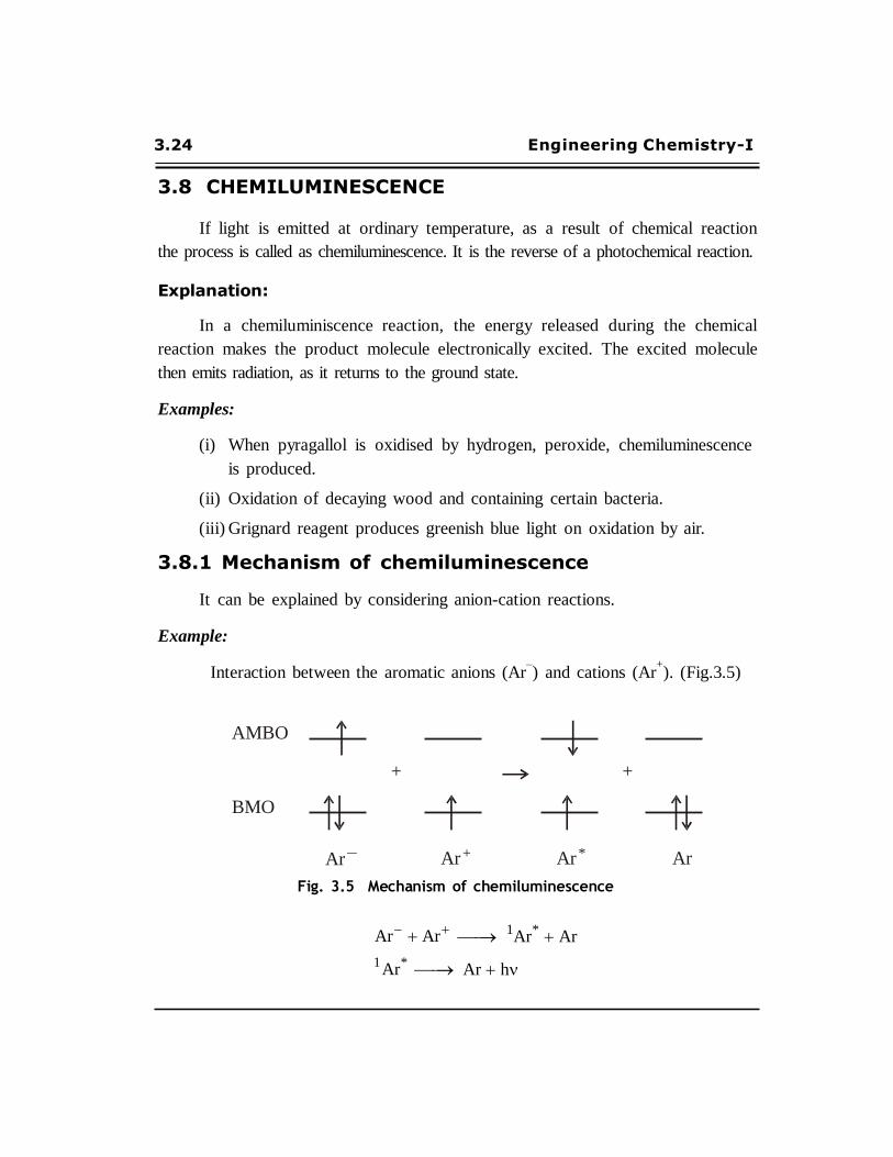
3.8.1 Mechanism of chemiluminescence
It can be explained by considering anion-cation reactions.
Example:
Interaction between the aromatic anions (Ar–) and cations (Ar
+). (Fig.3.5)
AMBO
+ +
BMO
Ar – Ar + Ar * Ar
Fig. 3.5 Mechanism of chemiluminescence
Ar Ar
1
Ar* Ar
1 Ar
*
Ar h
PHOTOCHEMISTRY & SPECTROSCOPY 3.25
The aromatic anion (Ar–) contains one unpaired electron in the antibonding
molecular orbital (AMBO) and two paired electrons in the bonding molecular
orbital (BMO). The AMBO of the aromatic cation Ar+
is empty. When the electron
is transferred from the AMBO of the anion (Ar–) to the AMBO of the cation (Ar
+).
So, the singlet excited state 1Ar
* is formed. The excited state can be deactivated by
the emission of photon h .
3.9 PHOTOSENSITIZATION
The foreign substance (called sensitizer) which absorbs the radiation and
transfers the absorbed energy to the reactants, is called a photosensitizer.
This process is called photosensitized reaction(or) photosensitization.
Examples:
(i) Molecular photosensitizers: Benzophenone, sulphurdioxide
(ii) Atomic photosensitizers: Cadmium, Mercury, Zinc, etc.
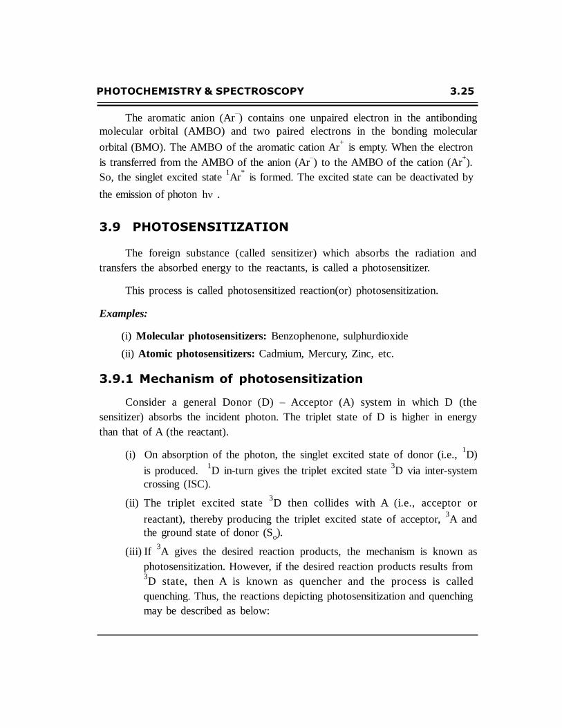
3.9.1 Mechanism of photosensitization
Consider a general Donor (D) – Acceptor (A) system in which D (the
sensitizer) absorbs the incident photon. The triplet state of D is higher in energy
than that of A (the reactant).
(i) On absorption of the photon, the singlet excited state of donor (i.e., 1D)
is produced. 1D in-turn gives the triplet excited state
3D via inter-system
crossing (ISC).
(ii) The triplet excited state 3D then collides with A (i.e., acceptor or
reactant), thereby producing the triplet excited state of acceptor, 3A and
the ground state of donor (So).
(iii) If 3A gives the desired reaction products, the mechanism is known as
photosensitization. However, if the desired reaction products results from 3D state, then A is known as quencher and the process is called
quenching. Thus, the reactions depicting photosensitization and quenching
may be described as below:
3.26 Engineering Chemistry-I
D h 1D
1 D ISC 3D
3 D A D
3 A
3 A products (photosensitization)
3 D products (Quenching)
1 1
D or S )
ISC
A ( 1
2D 2A
(or T1) (or T1)
S0
Donor, D
(Sensitizer)
S0
Acceptor, A
(Reactant)
Fig. 3.6 Mechanism of photosensitization
The triplet excited state of the sensitizer or donor (1D) must be higher in
energy level than the triplet excited state of the reactant or acceptor (3A) so that
enough energy is available to raise the reactant molecule to its triplet excited
state.
Examples for photosensitized reactions:
1. Dissociation of H2
molecule.
2. Photosynthesis in plants.
PHOTOCHEMISTRY & SPECTROSCOPY 3.27
SPECTROSCOPY
3.10 INTRODUCTION
Analytical technique is a powerful tool used to study the structure of atoms and
molecules. It is also used in the analysis of various compounds.
It deals with the study of interaction of electromagnetic radiation with the matter.
During the interaction, the energy is absorbed or emitted by the matter. The
measurement of the absorbed or emitted radiation frequency is made using spectroscopy.
3.11 TYPES OF SPECTROSCOPY
The study of spectroscopy can be carried out by the following title.
1. Atomic spectroscopy
2. Molecular spectroscopy
3.11.1 Atomic spectroscopy
It is obtained due to the interaction of the electromagnetic radiation with atoms.
The atoms absorb radiation and gets excited from the ground state electronic energy
level to another level. The structure and energy levels of atoms can be obtained from
their atomic spectra.
3.11.2 Molecular spectroscopy
It is obtained due to the interaction of the electromagnetic radiation with
molecules. The molecules absorb radiation and get excited from the ground state
energy (electronic, vibrational and rotational) levels to another level. The structure,
stability and other useful informations of molecules can be obtained from molecular
spectra.
3.28 Engineering Chemistry-I
E
Differences between atomic spectra and molecular spectra
S.No. Atomic spectra Molecular spectra
1
It is line spectra
It is a complicated spectra
2
It is due to electronic transition
from one lower level to another
higher level in an atom
It is due to electronic,
vibrational and rotational
transitions in a molecule.
3
It is due to the interaction of
atoms with electromagnetic
radiation.
It is due to the interaction of
molecules with electromagnetic
radiation.
3.12 SPECTRUM
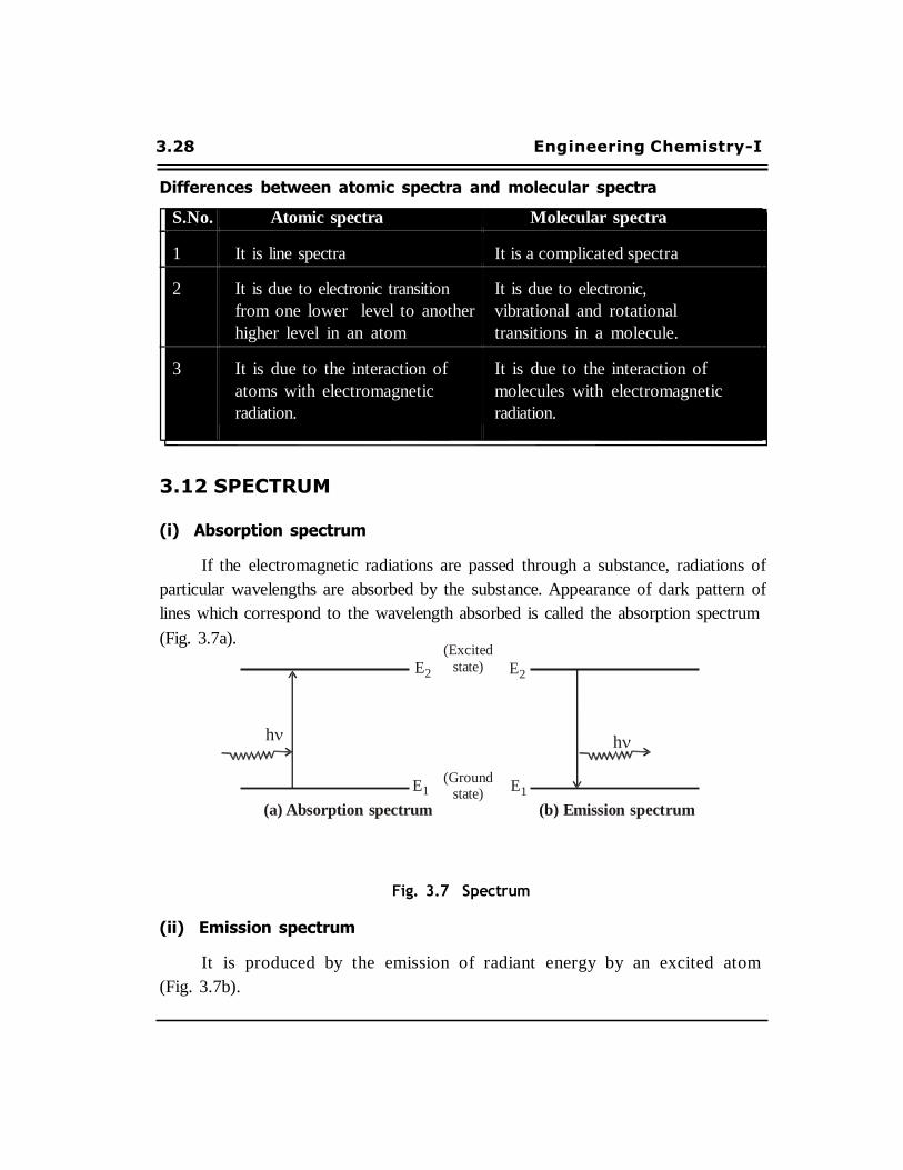
(i) Absorption spectrum
If the electromagnetic radiations are passed through a substance, radiations of
particular wavelengths are absorbed by the substance. Appearance of dark pattern of
lines which correspond to the wavelength absorbed is called the absorption spectrum
(Fig. 3.7a). (Excited
E2 state) E2
h h
(Ground 1 state)
E1
(a) Absorption spectrum (b) Emission spectrum
Fig. 3.7 Spectrum
(ii) Emission spectrum
It is produced by the emission of radiant energy by an excited atom
(Fig. 3.7b).
PHOTOCHEMISTRY & SPECTROSCOPY 3.29
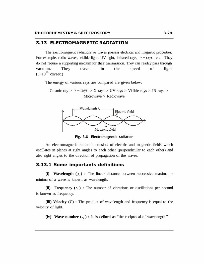
3.13 ELECTROMAGNETIC RADIATION
The electromagnetic radiations or waves possess electrical and magnetic properties.
For example, radio waves, visible light, UV light, infrared rays, rays, etc. They
do not require a supporting medium for their transmission. They can readily pass through
vac uum. T he y t r avel in t he spee d o f lig ht
(3×10¹⁰
cm/sec.)
The energy of various rays are compared are given below:
Cosmic ray > rays > X-rays > UV-rays > Visible rays > IR rays >
Microwave > Radiowave
Fig. 3.8 Electromagnetic radiation
An electromagnetic radiation consists of electric and magnetic fields which
oscillates in planes at right angles to each other (perpendicular to each other) and
also right angles to the direction of propagation of the waves.
3.13.1 Some importants definitions
(i) Wavelength ( ) : The linear distance between successive maxima or
minima of a wave is known as wavelength.
(ii) Frequency ( ) : The number of vibrations or oscillations per second
is known as frequency.
(iii) Velocity (C) : The product of wavelength and frequency is equal to the
velocity of light.
(iv) Wave number ( ) : It is defined as “the reciprocal of wavelength.”

3.30 Engineering Chemistry-I
Relationship between and C
Relationship between wavelength, frequency, wave number and velocity is given
as
1
C
3.14 ELECTROMAGNETIC SPECTRUM
The electromagnetic spectrum can be defined as “the arrangement of all types
of electromagnetic radiation in order to their wavelengths or decreasing frequencies
is known as complete electromagnetic spectrum.”
100 10
1 10
2 10
3 10
4 10
6 10
8 10
16
X UV Visible Near Far Micro Radio
rays rays rays region IR IR waves waves
V I B G Y O R
3800 4800 4500 4900 5300 5800 6500 7600
Fig. 3.9 Complete magnetic spectrum
3.15 ABSORPTION OF RADIATION
When electromagnetic radiation is passed through a matter, the following
changes takes place.
(i) As the photons of electromagnetic radiations are absorbed by the matter,
vibrational changes or rotational changes, electronic transition may takes
place.
After absorption, molecules get excited from the ground state to excited
state. Then they reemit electromagnetic radiation (or) liberate energy
quickly in the form of heat.
PHOTOCHEMISTRY & SPECTROSCOPY 3.31
(ii) In some cases, the portion of electromagnetic radiation, which passes into
the matter, instead of being absorbed may be reflected or re-emitted or
scattered.
(iii) When the electromagnetic radiation is absorbed or scattered, it may undergo
changes in orientation or polarisation.
(iv) In some cases the molecules absorbs radiation and get excited.
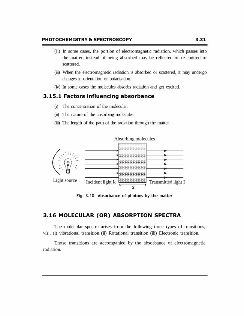
3.15.1 Factors influencing absorbance
(i) The concentration of the molecular.
(ii) The nature of the absorbing molecules.
(iii) The length of the path of the radiation through the matter.
Absorbing molecules
Light source
Incident light Io
Transmitted light I x
Fig. 3.10 Absorbance of photons by the matter
3.16 MOLECULAR (OR) ABSORPTION SPECTRA
The molecular spectra arises from the following three types of transitions,
viz., (i) vibrational transition (ii) Rotational transition (iii) Electronic transition.
Those transitions are accompanied by the absorbance of electromagnetic
radiation.

3.32 Engineering Chemistry-I
Energ
y
Ero
t E
rot
Ex
cite
d
elec
tro
nic
st
ate
G
roun
d e
lect
ron
ic s
tate
3.17 ENERGY LEVEL DIAGRAM
A molecule of a compound have a large number of energy levels. Small
amount of energy is required for transition between some of these while large
amount of energy is required for other levels.
The energy level diagram, showing different transitions in molecules are
shown in the diagram Fig.3.11.
V’ = 1
J’ = 4 J’ = 3
J’ = 2 J’ = 1
Evib
V’ = 0
J’’ = 4 J’’ = 3 J’’ = 2 J’’ = 1
V’’ = 2 V’’ = 1
Evib
V’’ = 0
Zero point energy
Fig. 3.11 Energy level diagram showing the various molecular energies
The various types of spectra, the regions in which these spectra lie and the
energy changes that takes place in the molecules due to absorption of radiation
are listed below.

PHOTOCHEMISTRY & SPECTROSCOPY 3.33
3.17.1 Vibrational spectra (or) Vibrational transition
It is associated with the to– and –fro motion of the nuclei of molecules such that
the centre of gravity does not change.
Vibrations of the atoms present in the molecule are causing vibrational energy level
spectrum.
The wavelength of infra red region is 8000 – 350000 Å. The frequency
ranges from 3.75×10¹⁴
to 8.6×10¹²
sec–1
. This is the low energy about 10 kJ region.
3.17.2 Rotational spectra (or) Rotational transition
It arises when the molecule rotates about an axis perpendicular to the inter-
nuclear axis and passing through the centre of gravity of the molecule. The rotation
of molecule with atoms causes rotational energy levels.
The rotational energy levels appear in microwave region which is a very low energy
level in the solar energy.
3.17.3 Electronic spectra (or) Electronic transition
Electronic energy arises due to the motion of electrons while considering the
nuclei of atoms of a molecule as fixed points. Electronic spectra results from the
transition of electron from the ground state energy level to an excited state energy
level of a molecule, due to the absorption of radiations in the visible and ultraviolet
regions. Electronic spectra occur in the visible region of 12,500 to 25,000 cm–1
those in the UV region of 25,000 to 70,000 cm–1
.

3.34 Engineering Chemistry-I
3.18 ULTRAVIOLET (UV) AND VISIBLE SPECTROSCOPY
3.18.1 Principle
UV-Visible spectra arises from the transition of valency electrons within a
molecule or ion from a lower electronic energy level (ground state E0) to higher
electronic energy level (excited state E1). This transition takes place due to the
absorption of UV (wavelength 100-400nm) or visible (wavelength 400-750 nm) region
of the electronic spectrum by a molecule (or) ion.
The actual amount of energy required depends on the difference in energy
between E0
and E1.
h E1 Eo
3.18.2 Types of electrons involved in organic molecule
The energy absorbed by an organic molecule involves transition of valency
electrons. The following three types electrons are involved in the transition.
S.No. Type of electron Examples Region Present in
1
-electrons
Saturated
hydrocarbons
CH3–(CH2)n–CH3
–
–
2. electrons Unsaturated hydro-
carbons and
aromatic compounds
UV or
Visible
C=C
or
C C
3 n-electrons Organic compounds
having N,O,X atoms
UV
Unshared (or)
non-bonded
electrons
The above three types of electrons are shown in the simple molecule
formaldehyde (HCHO).
PHOTOCHEMISTRY & SPECTROSCOPY 3.35
n *
n *
*
*
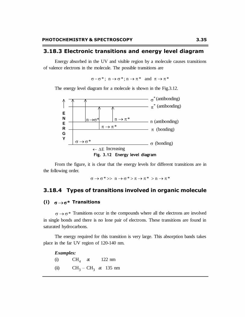
3.18.3 Electronic transitions and energy level diagram
Energy absorbed in the UV and visible region by a molecule causes transitions
of valence electrons in the molecule. The possible transitions are
* ; n * ; n * and *
The energy level diagram for a molecule is shown in the Fig.3.12.
* (antibonding)
* (antibonding)
E
N
E
R
G
Y
E Increasing
n (antibonding)
(bonding)
(bonding)
Fig. 3.12 Energy level diagram
From the figure, it is clear that the energy levels for different transitions are in
the following order.
* n * * n *
3.18.4 Types of transitions involved in organic molecule
(i) σ σ * Transitions
* Transitions occur in the compounds where all the electrons are involved
in single bonds and there is no lone pair of electrons. These transitions are found in
saturated hydrocarbons.
The energy required for this transition is very large. This absorption bands takes
place in the far UV region of 120-140 nm.
Examples:
(i) CH4
at 122 nm
(ii) CH3 – CH3 at 135 nm

3.36 Engineering Chemistry-I
(ii) n * Transitions
n * transitions occur in the saturated compounds having lone pair (non-
bonding) of electrons in addition to * transitions. As the energy required
for n * transitions is less than * transitions. This absorption bands takes
place at longer wavelength in the near UV region (180 - 200 nm).
Example:
Tr imet hylamine ( (CH3 )3 N) : n *
o c cur s
max at 227 nm a nd
* occurs at
max 100nm.
(iii) *
*
Transitions
transitions occur due to the transition of an electron from a bonding
orbital to an antibonding * orbital. Molecules having electron system
(unsaturated hydrocarbons and aromatic compounds) exhibit these transitions. But,
selection rules determine whether transitions to a particular
or forbidden.
* orbital is allowed
Example:
UV spectrum of ethylene :
It shows two bands – one at 174nm, an intense band and at 200nm, a
weak band. Both are due * to transitions. As per the selection
rules, the intense band at 174 nm is due to allowed transition.
UV spectrum of unsaturated ketone
methyl vinyl ketone
: O : ||
CH 2 CH
This compounds shows
C CH3
Low intensity band at 324 nm. This is due to n *
transition.
High intensity band at 219 nm. This is due to
*
transition.
PHOTOCHEMISTRY & SPECTROSCOPY 3.37
(iv) n *
n *
Transitions
transitions are shown by unsaturated molecules containing hetero atoms
like N,O,S and X. It occurs due to the transition of non-bonding, lone pair of electrons
to the antibonding orbitals ( * ). This transition shows a weak band and takes
place in longer wavelength with low intensity.
Examples:
Aldehydes and ketones having no C=C or C C bonds like acetaldehyde,
acetone.
At 270-300 nm, weak n *
transitions are found in them.
n *
transition takes place in the range of 270-300nm.
Aldehydes and ketones having double bond like
CH3 – CH = CH – CO – CH3
n * transition takes place in the range of 300-350nm.
3.18.5 Important terms used in UV-visible spectroscopy
(i) Chromophores (colour producing groups)
The presence of one or more unsaturated groups in a compound is mainly
r esponsible for the co lour o f t he compound. This gro ups are called as
chromophores.
Examples:
C C ; C C ; C N ; N N ; C O ; etc.
(ii) Chromogen
The compound containing the chromophoric group is called chromogen.
(iii) Auxochromes
Certain groups, which did not cause any colour effects in the absence of
chromophoric groups. It refers to an atom or a group of atoms which does not
3.38 Engineering Chemistry-I
give rise to absorption band on its own, but when conjugate to chromophore will cause
a red shift. Such groups are called as auxochromes or colour augmenters or deepeners.
Examples:
–OH, –OR, –NH2, –NHR, –NR
2 , –X
(iv) Some important definitions related to change in wavelength and intensity
(a) Bathochromic shift or shift: A shift of an
is called bathochromic shift.
max towards longer wavelength
(b) Hypsochromic shift or blue shift: A shift of an
wavelength is called hypsochromic shift.
max towards shorter
(c) Hyperchromic effect: It is an effect leading to an increased absorption
intensity.
(d) Hypochromic effect: It is an effect leading to decreased absorption
intensity.
Illustrations :
In bromo ethylene CH2 =CHBr, C=C is a chromo phor e and Br is an
auxochrome.
Substitution of a hydrogen atom in ethylene by a halogen atom causes a
bathochromic shift and a hyperchromic effect.
3.18.6 Instrumentation
I. Components
The most important components of UV-Visible spectrometer are
(i) Radiation source
(ii) Monochromators
(iii) Cells
(iv) Detectors
(v) Recorder
(i) Radiation source
Hydrogen or deuterium lamps are commonly used as radiation source.

PHOTOCHEMISTRY & SPECTROSCOPY 3.39
De
tec
tor
Requirements of a radiation source : It must be stable and supply continuous
radiation, sufficient intensity.
Source
Monochromator
sample Recorder
Beam
splitter
reference
Fig. 3.13 Block diagram of uv-visible spectrophotometer
(ii) Monochromator:
Selects appropriate wavelength of light. The important elements of a
monochromator are
an entrance slit
a dispersing element
an exit slit
The dispersing element may be a prism or a grating or a filter.
(iii) Cells
It is made out of quartz or fused silica. The cells must contains the following
characteristics
They must be uniform in construction.
The material of cell should be inert to solvents.
They must transmit the light of the wavelength used.
(iv) Detectors
The most commonly used detectors are
(a) Barrier layer cell

3.40 Engineering Chemistry-I
(b) Photomultiplier tube
(c) Photocell
These detectors converts light radiations into electrical signals.
(v) Recorder
The signal from the detector is finally received by the recorder.
II. Working of UV-Visible spectrometer
The radiation from the source is allowed to pass through the monochromator unit.
The monochromator allows a narrow range of wavelength to pass through an exit slit.
The beam of radiation coming out of the monochromator is split into two equal
beams. One half of the beam is directed to pass through a transparent cell containing
a solution of the compound to be analyzed. The another half is directed to pass through
an identical cell which contains only the solvent.
The instrument is designed in such way that it can compare the intensities of these
two beams.
If the sample absorbs light at a particular wavelength, then intensity of the sample
beam (I) will be less than that of the reference beam (I0).
The instruments give output graph, which is a plot of wavelength Vs. absorbance
of the light. The graph obtained is known as absorption spectrum.
3.18.7 Applications of UV-Visible spectroscopy
( i ) Determination of molecular weight
Molecular weight of a compound can be determined if the compound forms a
suitable derivative which gives an absorption band.
( i i ) Determination of calcium in blood serum
Calcium in blood serum can be estimated by using electronic absorption spectra.
( i i i ) Studying kinetics of chemical reactions
UV-Visible spectroscopy can be used to study the kinetics of a reaction.
Generally absorbance is directly proportional to the concentration. Hence,
PHOTOCHEMISTRY & SPECTROSCOPY 3.41
absorbance is measured at different intervals of time. From the data obtained, the kinetics
of the reaction is studied.
(iv) Determination of inorganic substance
UV spectrometry can be used for the determination of inorganic substances. For
examples
Many metals (Mg, Mo, Nb, Ni, Al, Au, Cu, Cd) non-metals (B, Br2, Cl
2,Si)
– – – - and anions (NO3 , Cl , I , NO2 )
Ammonia
Lead in bone ash
(v) Identification of electron
UV and Visible spectroscopy is generally used for the identification of the
presence of a conjugated electron in a given compound.
(vi) Predicting relationship between different groups
UV Spectroscopy is used in predicting the relationship between different
functional groups.
– between two or more C–C multiple bonds (double or triple bonds)
– between C–C and C–O double bonds
– between C–C double bonds and aromatic benzene ring
(vii) Detection of purities
Ultraviolet absorption spectra have been used for the identification of
degradation products and for testing the purity in biological and pharmaceutical
research.
(viii) Determination of concentration of ozone
The concentration of ozone in urban smog was measured using UV
spectroscopy.
3.42 Engineering Chemistry-I
a
(ix) Detection of impurities
The impurities in organic compounds can be detected using electronic spectra since
the bands due to impurities are very intense. Saturated compounds have little absorption
band and unsaturated compounds have strong absorption band.
(x) Determination of vitamin
UV-spectroscopy is the best method for determining the structure of several
vitamins.
(xi) Dissociation constants of Acids and Bases
The dissociation constant (Pka) of an acid HA can be determined by
determining the ratio of [HA]/[A-] spectrophotometrically from the graph plotted
between absorbance Vs wavelength at different pH values. These values are
substituted in the equation
Pk = pH + log [HA] / [A–]
3.19 INFRARED SPECTROSCOPY
3.19.1 Principle
It is an important tool in the structural elucidation of organic compounds.
The region of electromagnetic radiation in between the visible and microwave
region is called infrared region. IR spectra is produced by the absorption of energy
by a molecule in the infrared region and the transitions occur between vibrational
levels.
Range of Infrared Radiation
The range in the electromagnetic spectrum extending from 12500 to
50 cm–1
is commonly referred to as the infrared.
The infrared region may be divided into the following three regions for
convenience.
(i) Near infrared : The region is from 12500 to 4000 cm–1
.
(ii) Infrared (or) Ordinary IR : The region is form 4000 to 667 cm–1
.
(iii) Far infrared : The region is from 667 to 50 cm–1
.

PHOTOCHEMISTRY & SPECTROSCOPY 3.43
=0.8 2.5 15 20
Near IR
IR
Far IR
V=12500 4000 667 50 cm-1
Fig. 3.14 Range of IR radiation
3.19.2 Molecular Vibrations
The absorption of infrared radiations causes vibration in a molecule. There are
two types of fundamental vibrations in a molecule.
(i) Stretching
(ii) Bending
(i) STRETCHING VIBRATIONS
In this type of vibrations, the bond length increases or decreases but the bond
angle remains unlatered.
Types of stretching vibrations
(a) Symmetric stretching
(b) Asymmetric stretching
(a) Symmetric stretching
In this t ype, at oms moves in a same
direction with respect to the central atom.
(b) Asymmetric stretching
In this type, one atom approaches the central
atom while the other atom departs from it.

3.44 Engineering Chemistry-I
(ii) BENDING VIBRATIONS
In this type of vibrations, the bond angle changes but the bond length remains
unaltered.
Types of bending vibrations
(a) Scissoring
(b) Rocking
(c) Wagging
(d) Twisting
(a) Scissoring :
Two atoms approach each other.
(b) Rocking :
Scissoring Rocking
+ + + -
Wagging Twisting
The movement of the atoms takes place in the same direction.
(c) Wagging : Two atoms move up and down the plane with respect to
the central atom.
(d) Twisting : One of the atom moves up the plane while the other moves
down the plane with respect to the central atom.
3.19.3 Types of Stretching and Bending Vibrations
(i) For non-linear molecule
A non-linear molecule containing ‘n’ atoms has (3n-6) fundamental vibrational
modes.
PHOTOCHEMISTRY & SPECTROSCOPY 3.45
Example :
(a) Methane (CH4)
Fundamental vibrational modes = 3n – 6
= 3 × 5 – 6
(b) Benzene (C6H
6)
= 15 – 6 = 9
Fundamental vibrational modes = 3n – 6
= 3 × 12 – 6
(c) Water (H2O)
= 36 – 6 = 30
Fundamental vibrational modes = 3n – 6
= 3 × 3 – 6
=
9 – 6 = 3
Stretching vibrational modes =
=
n – 1
3 – 1
= 2
These are (i) Symmetric stretching
(ii) Asymmetric stretching
Hence,
The number of bending vibrations = Fundamental – Stretching vibrational
vibrational modes modes
= 3 – 2 = 1
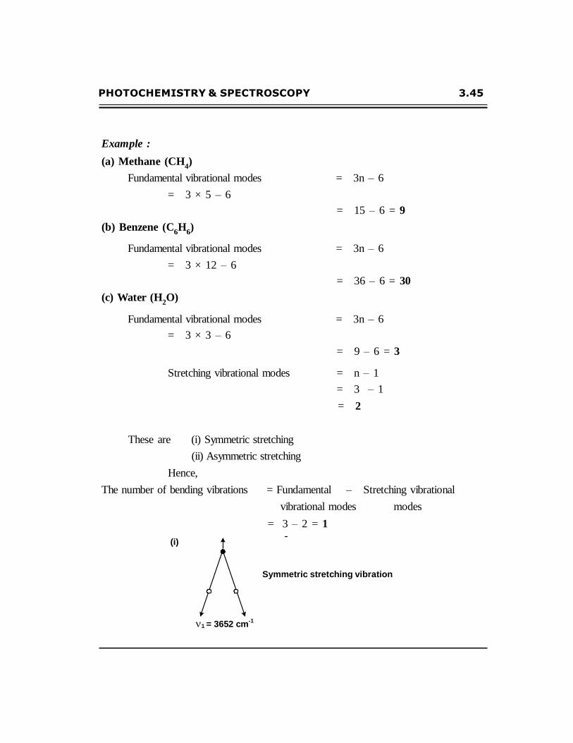
(i)
Symmetric stretching vibration
1 = 3652 cm-1
3.46 Engineering Chemistry-I
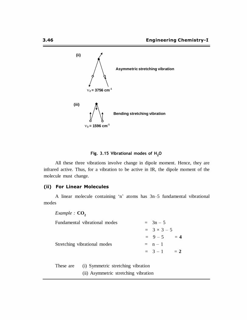
(ii)
Asymmetric stretching vibration
2 = 3756 cm-1
(iii)
Bending stretching vibration
3 = 1596 cm-1
Fig. 3.15 Vibrational modes of H2O
All these three vibrations involve change in dipole moment. Hence, they are
infrared active. Thus, for a vibration to be active in IR, the dipole moment of the
molecule must change.
(ii) For Linear Molecules
A linear molecule containing ‘n’ atoms has 3n–5 fundamental vibrational
modes
Example : CO2
Fundamental vibrational modes = 3n – 5
= 3 × 3 – 5
= 9 – 5 = 4
Stretching vibrational modes = n – 1
= 3 – 1 = 2
These are (i) Symmetric stretching vibration
(ii) Asymmetric stretching vibration
PHOTOCHEMISTRY & SPECTROSCOPY 3.47
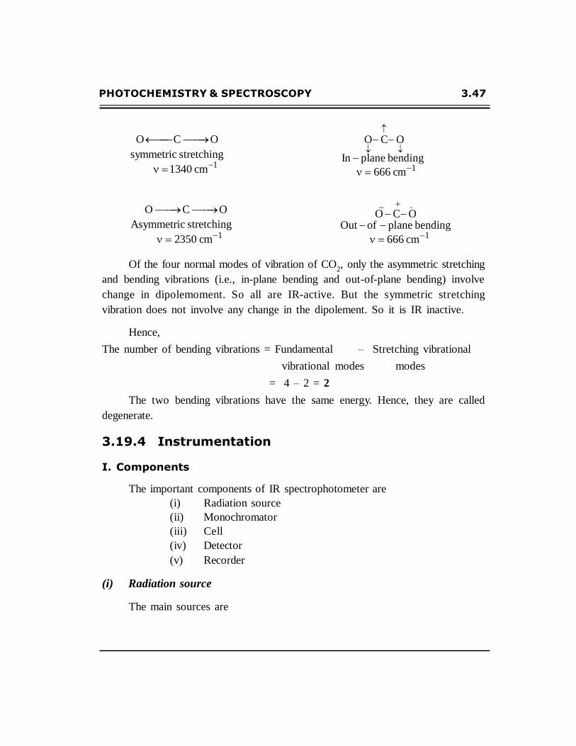
O C O
symmetric stretching
1340 cm1
O C O
In plane bending
666 cm1
O C O
Asymmetric stretching
2350 cm1
O C O Out of plane bending
666 cm1
Of the four normal modes of vibration of CO2, only the asymmetric stretching
and bending vibrations (i.e., in-plane bending and out-of-plane bending) involve
change in dipolemoment. So all are IR-active. But the symmetric stretching
vibration does not involve any change in the dipolement. So it is IR inactive.
Hence,
The number of bending vibrations = Fundamental – Stretching vibrational
vibrational modes modes
= 4 – 2 = 2
The two bending vibrations have the same energy. Hence, they are called
degenerate.
3.19.4 Instrumentation
I. Components
The important components of IR spectrophotometer are
(i) Radiation source
(ii) Monochromator
(iii) Cell
(iv) Detector
(v) Recorder
(i) Radiation source
The main sources are
3.48 Engineering Chemistry-I
De
tec
tor
(a) Nernst glower :
It consists of a rod of the sintered mixture of oxides of Zr, Y and Er. This rod
is electrically heated to 1500oC to produce IR radiation.
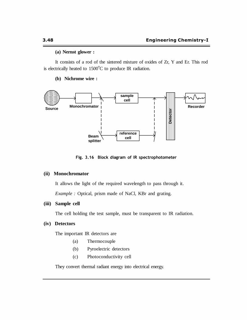
(b) Nichrome wire :
Source
Monochromator
sample
cell
Recorder
Beam
splitter
reference
cell
Fig. 3.16 Block diagram of IR spectrophotometer
(ii) Monochromator
It allows the light of the required wavelength to pass through it.
Example : Optical, prism made of NaCl, KBr and grating.
(iii) Sample cell
The cell holding the test sample, must be transparent to IR radiation.
(iv) Detectors
The important IR detectors are
(a) Thermocouple
(b) Pyroelectric detectors
(c) Photoconductivity cell
They convert thermal radiant energy into electrical energy.
PHOTOCHEMISTRY & SPECTROSCOPY 3.49
(v) Recorder
The recorder records the signal coming out from the detector.
II. Working or IR Spectrophotometer
The radiation emitted by the source is split into two equal, identical beams having
equal intensity.
One of the beams passes through the sample and the other through the reference
sample. When the sample cell contains the sample, the half beam travelling through it
becomes less intense.
When the two half beams (one coming from the reference and the other from
the sample) recombine, they produce an oscillating signal. This signal is measured
by the detecor. The signal from the detector is passed to the recorder unit and
recorded.
3.19.5 Applications of IR Spectroscopy
(i) Hydrogen bonding
It is a powerful and widely used for studying hydrogen bonding as it
decreases the vibrational frequency considerably and the decrease depends on the
strength and nature of hydrogen bonding.
There are two types of hydrogen bonding is there.
(i) Intermolecular hydrogen bonding
(ii) Intramolecular hydrogen bonding
(ii) Testing purity of a sample
Pure sample will give a sharp and well-resolved absorption bands. But impure
sample will give a broad and poorly resolved absorption bands. By comparison
with IR spectra of pure compound, presence of impurity can be detected.
(iii) Progress of reaction
Infrared spectroscopic method can be used follow the progress of a reaction.
The examination of a small portion of the spectrum is sufficient to indicate whether the
desired product is formed or not.

3.50 Engineering Chemistry-I
(iv) To study tautomerism
Tautomeric equilibria can be studied with the help of IR spectroscopy.
Example :
The common systems like keto-enol, mercapto-thioamide, lacto-lactam contain
group such as C=O, –OH, –NH (or) C=S. These groups show a characteristic
absorption band in the IR spectrum, which enable us to find out which form
predominates in the equilibrium.
(v) IR spectra is used recently for identifying inorganic materials like ferricyanide,
ferrocyanide, all types of phosphates, nitrate, etc.
(vi) Determination of molecular weight
Mo lecular weight o f a co mpo und can be det er mined by using I R
spectroscopy.
(vii) Crystallinity
The physical property like crystallinity, can be studied through changes in
IR spectra.
(viii) Determination of structure of chemical products
During the polymerisation, the polymer structure can be determined using
IR spectra.
(ix) It can be used to study the structure of coordination compounds.
PHOTOCHEMISTRY & SPECTROSCOPY 3.51
ANNA UNIVERSITY QUESTIONS
AND EXPECTED QUESTIONS
1. Define Beer-Lambert’s law. (TAU, Jan.2000)
2. Derive Beer-Lambert’s law and write all the limitations observed in the quantitative
analysis. (Chen.AU, June 2009)
3. Derive the expression for the Beer-Lambert’s law. State its disadvantages.
(Coim. AU, July 2009)
4. Explain Stark-Einstein law of photochemical equivalence.
5. State Grotthus-Draper law.
6. Explain the conditions and causes for law and high quantum yield.
7. Explain the determination of quantum yield.
8. Define quantum yield.
9. With a Jablonski diagram, explain radiative and non-radiative pathways for
an electronic transition.
10. Wha t is che milu mine scence? Br ing o u t t he me chanisms o f
chemiluminescence.
11. What is photosensitization? Bring out the mechanisms of photosensitization.
12. What are the types of photophysical process? Explain.
13. Define Interconversion and Inter system crossing.
14. Explain electromagnetic spectrum.
15. Explain the different changes occuring during absorption of radiation? What
are the factors influencing it?
16. Explain in detail about the rotational, vibrational and electronic transitions.
3.52 Engineering Chemistry-I
17. What are the limitations of flame photometry.
(Coim.AU, May 2011, July 2009)
18. How is sodium estimated by Flame photometer? (Coim.AU, May 2011,
19. Describe the estimation of nickle by atomic absorption spectroscopy method.
(TAU, Jan.2010)
20. Mention the applications for IR spectroscopy. (Coim.AU, July 2010)
21. Calculate the frequency of radiations having wavelength 5000 Å.
Where C = 2.996×1010 cm/s. (Coim. AU, July 2010)
22. Discuss the application of uv spectroscopy. (Coim.AU, July 2010)
23. Explain the estimation of nickel by atomic absorption spectroscopy.
(Coim.AU, July 2009)
24. Mention few applications of calorimetry. (Coim.AU, Dec.2009)
25. Describe the components and working principle of an IR spectrophotometer
with a block diagram. (Coim.AU, Dec.2009)
26. Discuss how Nickel is estimated using atomic absorption spectroscopy.
(Coim. AU. Dec.2009)
27. Discuss in detail the principle and instrumentation of UV-visible spectroscopy.
(TAU, July 2009)
28. E xplain briefly t he pr inciple and applicat ions o f flame pho to met ry.
(TAU, July 2009)

![CHARACTERIZATION AND PHOTOCHEMISTRY OF SURFACE … · spectroscopy. The photochemistry of [Si02]-L3Ru3(CO)9 involves metal-metal bond rupture; under 1 atm CO in a solid/gas reaction](https://static.fdocuments.net/doc/165x107/5f4c154e5f3b2547ff0a0e1d/characterization-and-photochemistry-of-surface-spectroscopy-the-photochemistry.jpg)