
PHOSPHORIC ACID PRODUCTIONqu.edu.iq/eng/wp-content/uploads/2018/06/2...Wet Process Acid Production...
61
1 University of Alqadisia COLLEGE OF ENGINEERING CHEMICAL ENGINEERING DEPARTMENT YEAR 2018-2017 PHOSPHORIC ACID PRODUCTION By Reda Hussein Karrar sahib Ali atwan Supervisor Mustafa jawed
Transcript of PHOSPHORIC ACID PRODUCTIONqu.edu.iq/eng/wp-content/uploads/2018/06/2...Wet Process Acid Production...

1
University of Alqadisia COLLEGE OF ENGINEERING
CHEMICAL ENGINEERING DEPARTMENT
YEAR
2018-2017
PHOSPHORIC ACID PRODUCTION
By
Reda Hussein
Karrar sahib
Ali atwan
Supervisor
Mustafa jawed

2
بـــــــسم هلال الرحمن الرحيم
لع ا ن تم ا
ملع ل ما ال ك ا ن ل
بساح
ن
او لا ق
ميل علا ميكح
ت لا أنإنك
)32سورة البقرة اآلية (

3
DEDICATION
The beginning, "Thank Allah for the completion of this project and ask Allah Almighty to benefit him, and then
ones loved and families our to modest search this dedicate
to all who support us and helped us to complete this project

4
CHAPTERONE
Introduction .......................................................................... 1
Physical Properties ................................................................ 2
Chemical Properties .............................................................. 2
of Production Method ........................................................... 3
ProductionAcid Wet Process ............................................. 4
Acid Production Thermal Process ....................................... 6
1.5 of Production Choice ............................................................ 8
CHAPTER TWO
MATERIAL AND ENERGY BALANCE
Material Balance ................................................................... 9
Mill Material Balance On .................................................. 11
Reactor Material Balance On ........................................... 12
Filter Material Balance On ................................................ 16
Evaporator Material Balance On ....................................... 17
Tank Material Balance On Mixing .................................... 18
Absorber Material Balance On .......................................... 19
Balance Over All Material ............................................... 20
of Process General Diagram .............................................. 20
Balance Energy ................................................................... 21
Reactor On Energy Balance ............................................. 22
Filter On Energy Balance .................................................. 24
Mixing Tank Energy Balance On ...................................... 25
Evaporator On Energy Balance ......................................... 26
Absorber On Energy Balance ............................................ 27
CHAPTER THREE
EQUIPMENT DESIGN
Reactor OnDesign .............................................................. 28
Vessel Mixing Mechanical Design for .............................. 31
Design Absorber ................................................................. 36
Tower Height Calculation The .......................................... 37
Column Calculation The Area of ...................................... 38
of HOG Estimate ............................................................... 39
drop Pressure .................................................................... 41
Mechanical Design ........................................................... 42
End Domed Design of ...................................................... 42
Design Evaporator .............................................................. 44
Bundle Tubes Calculate of ................................................44
drop Pressure Tube side ................................................... 45
5
of Evaporator Volume… ................................................... 47
Length of Evaporator ....................................................... 47
TimeResidence Calculate of ............................................ 47
Mechanical Design ........................................................... 48
of Cover Thickness… ....................................................... 48
of Evaporator Weight ........................................................48
with Water Weight of Vessel Filled .................................. 49
Weight of Tube… .......................................................... 49
Weight of Cover .............................................................. 49
Total Weight .................................................................. 49
CHAPTER FIVE
CONSEDRATIONS LOCATION, ECONOMI AND SAEFTY
Selection Site Plant Location and ......................................... 52
Environmental Consecrations Safety and ............................. 52
Economic ............................................................................ 54
6
CHAPTER ONE
)1( Introduction
Phosphoric acid was discovered in 1770 by K. W. Scheele and J. G.
(1774) ash bone from phosphorus isolated later Scheele ash. bone in Gann
phosphoric acid by the action of nitric acid on and produced (1777)
phosphorus
bury. Old at founded was Ltd Wilson, and Albright later, years 9 Some
treating by ash bone from obtained was phosphorus white days, early the In
phosphates. Then them with hydrochloric acid to produce precipitated
retort, a in crucible, sealed a in days several for phosphate Meta the heating
and distilling off phosphorus vapor, under water. Huge quantities of coal
retort were needed for heating these.
by using phosphate The production of white phosphorus was improved
rock and sulfuric acid instead of bone ash and hydrochloric acid; and by
heated furnace-the use of reverberator furnaces instead of the direct.
White and amorphous phosphorus remained the main product of Albright
ar 1and Wilson until World W.
Phosphoric acid or tri hydroxide phosphorus and other names (ortho
phosphoric acid, tri hydroxyl phosphine oxide.(
Phosphoric acid is used as an additive and flavoring agent in both
or pShar a provide to sodas in used commonly is It feed animal and human
sour flavor. In fact almost all the acidic flavor in soda Comes from
phosphoric acid as the carbonic acid contained in the Bubbles has little
effect on the overall ph. Phosphoric acid also helps to keep bacteria and
drinks fungi from forming in these sugary
Phosphorous is one of the most essential plant nutrients in order to add
extra phosphorous to soil , phosphoric acid is converted into Phosphates
that are then mixed in with other ingredients to form Fertilizer more than
80 acid produced in the world is used in the percent of the phosphoric
manufacture of fertilizer.

7
)1( Physical Properties
Table (1) shows the physical properties of phosphoric acid
MOLECULAR FORMULA H3PO4
CHEMICAL NAME Ortho phosphoric acid
COMMON NAME phosphoric acid
SOLUBILITY miscible in water
Molecular Weight 98.00
Boiling Point o C 213
Melting Point o C 42.35
Density/Specific Gravity tribasic acid (at 25 o C)
Vapor Pressure mm Hg at 20 o C 0.03
Vapor Density 3.4
Conversion Factor ppm = 4.01 mg/m3 1
)1( Chemical properties
Mineral acid is the chemical formula H3PO4 Phosphoric acid is made
up of a dense crystalline solid colorless and odorless and is often used as
a solution of water, where it dissolves in the water and reach the boiling
230.5 acid point of phosphoric .for Phosphoric acid is the main source
the first phosphor used in the phosphate fertilizer industry. And
phosphoric acid canker cause irritation of the skin and eyes touching and
if es, as it leads to poisoningthe occurrence of ulcers membranes and tissu
swallowed or inhaled. As the phosphoric acid is a source of phosphorus
necessary for the growth of aquatic plants it is possible to contribute
phosphoric acid Lagoon in stagnant water bodies or slow flow, especially
rfaces with low content of phosphorus. And so far it has not been those su
causing -proven scientifically that phosphoric acid from cancer
substances. In nature, the minerals that cause water hardness reduce the
soil until plants use degree of acid and phosphate salts still remain in the
natural fertilizer.
H2SO4 )l( + Ca3 )PO4(2)s( + 6 H2O )l( → 2 H3PO4)s( + 3 CaSO4.2 H2O)s) 3
)PHOSPHATE ROCK( )GYPSUM(

8
SIDE REACTIONS:
→ CaF2 +H2SO4 + 2H2O 2HF +CaSO4 .2H2O
6HF +SiO2 → H2SiF4 + 2H2O
)2( Method of production
Wet Process Acid Production
Production Thermal Process Acid
:Phosphoric acid (H3PO4) is produced by 2 commercial methods
wet process and thermal process. Wet process phosphoric acid is used in
higher much a of is acid phosphoric process Thermal production. fertilizer
purity and is used in the manufacture of high grade chemicals,
pharmaceuticals, detergents, food products, beverages, and other no
fertilizer products. In 1987, over 9 million mega grams (Mg) (9.9 million
ocess phosphoric acid was produced in the form of tons) of wet pr
phosphorus pent oxide (P2O5). Only about 363,000 Mg (400,000 tons) of
P2O5 was produced from the thermal process. Demand for phosphoric acid
year has increased approximately 2.3 to 2.5 percent per.
considerable a generates acid phosphoric process wet of production The
quantity of acidic cooling water with high concentrations of phosphorus
and fluoride. This excess water is collected in cooling ponds that are used
to and evaporation subsequent for precipitation excess store temporarily to
use. Leachate -allow recirculation of the process water to the plant for re
seeping is therefore a potential source of groundwater contamination.
Excess rainfall also results in water overflows from settling ponds.
phosphorus of level acceptable an to treated be can water cooling ,However
necessary and Fluoride if discharge is.

9
Production Wet Process Acid
In a wet process facility, phosphoric acid is produced by reacting
sulfuric acid (H2SO4) with naturally occurring phosphate rock. The
reactor the into fed continuously then and crushed, dried, is rock phosphate
along with sulfuric acid. The reaction combines calcium from the
phosphate rock with sulfate, forming calcium sulfate (CaSO4), commonly
referred to as gypsum. Gypsum is separated from the reaction solution by
filtration. Facilities in the U. S. generally use a dehydrate process that
produces gypsum in the form of calcium sulfate with 2 molecules of water
(H2O) (CaSO4 2 H2O or calcium sulfate dehydrate). Japanese facilities use
a hemihydrate process that produces calcium sulfate with a half molecule
.of water (CaSO4 ½ H2O)
step hemihydrate process has the advantage of producing wet -This one
less and ation process phosphoric acid with a higher P2O5 concentr
S. U. some advantages, these to Due process. dehydrate the than impurities
companies have recently converted to the hemihydrate process. However,
since most wet process phosphoric acid is still produced by the dehydrate
hemihydrate process will not be discussed in detail here. A process, the
follow simplified reaction for the dehydrate process is as:
Ca3 )PO4(2 +3H2SO4 + 6H2O → 2H3PO4 + 3)CaSO4(. 2H2O
In order to make the strongest phosphoric acid possible and to decrease
costs, 94 percent sulfuric acid is normally used. Because the evaporation
proper ratio of acid to rock in the reactor is critical, precise automatic
process control equipment is employed in the regulation of these 2 feed
streams.
from separated and precipitated are crystals gypsum reaction, the During
to thoroughly washed be must crystals separated The filtration. by acid the
yield at least a 99 percent recovery of the filtered phosphoric acid. After
. washing, the slurred gypsum is pumped into a gypsum pond for storage
to the pond Water is syphoned off and recycled through a surge cooling
phosphoric acid Flow diagram of a wet process phosphoric acid plant.
required is area pond settling and cooling of hectares 0.3 Approximately

10
for every mega gram of daily P2O5 capacity (0.7 acres of cooling and
settling pond area for every ton of daily P2O5 capacity.(
was heat this plants, older In reactor. the in generated is heat Considerable
vacuum plants Modern surface. slurry hot the over air blowing by removed
reactor flash cool a portion of the slurry, and then recycle it back into the.
Wet process phosphoric acid normally contains 26 to 30 percent P2O5. In
most cases, the acid must be further concentrated to meet phosphate feed
of types the on Depending production. ilizerfert for specifications material
fertilizer to be produced, phosphoric acid is usually concentrated 40 to 55
.percent P2O5(75%H3PO4) by using 2 or 3 vacuum evaporators
Figure (1.1) Flow diagram of a wet process phosphoric acid plant
11
Production Thermal Process Acid
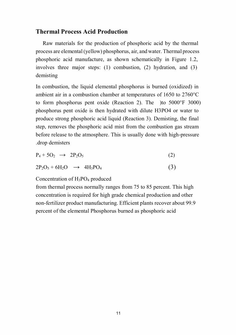
Raw materials for the production of phosphoric acid by the thermal
process Thermal water. and air, phosphorus, (yellow) elemental are process
1.2, phosphoric acid manufacture, as shown schematically in Figure
involves three major steps: (1) combustion, (2) hydration, and (3)
demisting
In combustion, the liquid elemental phosphorus is burned (oxidized) in
ambient air in a combustion chamber at temperatures of 1650 to 2760°C
)3000 to 5000°F )us pent oxide (Reaction 2). The to form phosphor
phosphorus pent oxide is then hydrated with dilute H3PO4 or water to
produce strong phosphoric acid liquid (Reaction 3). Demisting, the final
step, removes the phosphoric acid mist from the combustion gas stream
pressure -se to the atmosphere. This is usually done with highbefore relea
drop demisters.
P4 + 5O2 → 2P2O5 (2)
2P2O5 + 6H2O → 4H3PO4 (3)
Concentration of H3PO4 produced
from thermal process normally ranges from 75 to 85 percent. This high
high grade chemical production and other concentration is required for
fertilizer product manufacturing. Efficient plants recover about 99.9 -non
percent of the elemental Phosphorus burned as phosphoric acid

12
H2O
Sand breeze coke Water dioxide carbon
Water
slag air
Ferro phosphorus
Phosphoric
Sulfide Hydrogen Acid )50%(
Figure (1.2) Flow diagram of Thermal process phosphoric acid plant
Phosphate
Rock
Sintering
and sizing
Dilution
Tank
Phosphoric
Acid )85%(
Sand filter
Purifier
Co
ttre
ll p
recip
ita
tor
Hyd
rato
r
Electric
furnace
13
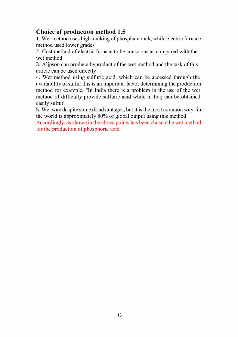
1.5 Choice of production method 1. furnace electric while rock, phosphate of ranking-high uses method Wet
grades method used lower
2. Cost method of electric furnace to be conscious as compared with the
wet method
3. Aljpson can produce byproduct of the wet method and the task of this
directly article can be used
4. Wet method using sulfuric acid, which can be accessed through the
production the determining factor important an is this sulfur of availability
method for example, "In India there is a problem in the use of the wet
furic acid while in Iraq can be obtained method of difficulty provide sul
sulfur easily
5. "in way common most the is it but disadvantages, some despite way Wet
the world is approximately 80% of global output using this method
method wet the chosen been has points above the in shown as Accordingly,
acid for the production of phosphoric

14
CHAPTER TWO
Material Balance
Main Reaction :-
Ca3 (PO4)2 + 3H2SO4 +6H2O
(1) ..…… 2H3PO4 + 3(CaSO4. 2H2O) →
ReactionsSide :
CaF2 + H2SO4
→ 2HF + CaSO4
) ..……2(
6HF + SiO2 → H2SiF6 +2H2O ) ..………3(
Raw Materials:
wt Phosphate Rock Analysis % by.
Ca3 (PO4)2 75
CaF2 20
SiO2 5
H2SO4 concentration %94
Assumptions :-
Production of H3PO4 =300 Ton/year =1000 Kg/day
Year = 300day
1.5) percent is allowed to go with gypsum to -Some sulfuric acid (1
filterable make it easily.
Excess of H2SO4 =15%
95% Yield =

15
Component M.wt
H3PO4 98
H2SO4 98
SiO2 60
CaF2 78
H2O 18
Ca(PO4)2 310
CaSO4 136
CaSO4.2H2O 172
HF 20
H2SiF6 144
P2O5 142
Production of H3PO4 =1000 Kg/day = 42Kg/hr. = 0.428Kgmole/hr.
Stream of product = 42/0.75= 56Kg/hr.
.H2O= 56*0.25 = 14 Kg/hr
reactionFrom )1(
Reacted of Ca3 (PO4)2 = 1/2*0.428 = 0.214Kgmole/hr. =
Kg66.34/hr.
Yield = product H3PO4
feed Ca3(PO4)2
Ca3 (PO4)2 feed = 0.428/0.95 = 0.45Kgmole/hr. = 139.5Kg/hr.
Feed steam = 139.5/0.75 = 186 Kg/hr.
.CaF2 = 0.2 * 186 = 37.2 Kg/hr
.SiO2= 0.05 *186 = 9.3 Kg/hr
Phosphate Rock, Kg/hr.
Ca3 (PO4)2 139.5
CaF2 37.2
SiO2 9.3

16
Mill
Martial Balance on Mill: -
Dilute phosphoric acid stream
acid Phosphoric 15% wt.
H2O .wt %85
Assume 50 Kg of dilute H3PO4 /100 Kg Phosphate Rock
Kg /hr. (H2O+H3PO4 dilute) 93 = 100/50 *186
.H3PO4 = 14 Kg/hr
.H2O = 79 Kg /hr
Dilute phosphoric acid (2)
H3PO4
H2O Ca3 (PO4)2
(1) (3) CaF2
Phosphate Rock SiO2
H2O
H3PO4
Composition Stream 1 Stream 2 Steam 3
Ca3(PO4)2 139.5 139.5
CaF2 37.2 37.2
SiO2 9.3 9.3
H2O 79 79
H3PO4 14 14
Mass in = 139.5 + 37.2 +9.3 +79 +14 = 279 Kg /hr.
Mass out= 139.5 +37.2 +9.3+79+14 = 279 Kg/hr.
Mass in = Mass out = 279 Kg/hr.
17
Re
act
or
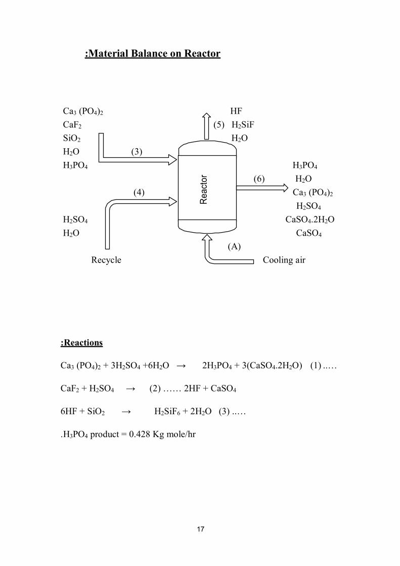
:Material Balance on Reactor
Ca3 (PO4)2 HF
CaF2 (5) H2SiF
SiO2 H2O
H2O (3)
H3PO4 H3PO4
(6) H2O
(4) Ca3 (PO4)2
H2SO4
H2SO4 CaSO4.2H2O
H2O CaSO4
)A(
Recycle Cooling air
:Reactions
Ca3 (PO4)2 + 3H2SO4 +6H2O → 2H3PO4 + 3(CaSO4.2H2O) (1) ..…
CaF2 + H2SO4 → (2) …… 2HF + CaSO4
6HF + SiO2 → H2SiF6 + 2H2O (3) ..…
.H3PO4 product = 0.428 Kg mole/hr
18
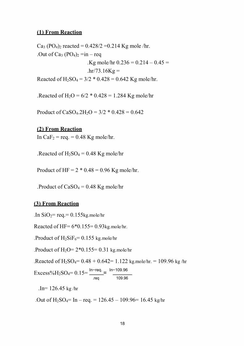
)1( From Reaction
Ca3 (PO4)2 reacted = 0.428/2 =0.214 Kg mole /hr.
.Out of Ca3 (PO4)2 =in – req
=0.45 – 0.214 =0.236 Kg mole/hr.
=Kg73.16/hr.
Reacted of H2SO4 = 3/2 * 0.428 = 0.642 Kg mole/hr.
.Reacted of H2O = 6/2 * 0.428 = 1.284 Kg mole/hr
Product of CaSO4.2H2O = 3/2 * 0.428 = 0.642
)2( From Reaction
In CaF2 = req. = 0.48 Kg mole/hr.
.Reacted of H2SO4 = 0.48 Kg mole/hr
mole/hr. Kg Product of HF = 2 * 0.48 = 0.96
.Product of CaSO4 = 0.48 Kg mole/hr
)3( From Reaction
.In SiO2= req.= 0.155kg.mole/hr
kg.mole/hr. Reacted of HF= 6*0.155= 0.93
.Product of H2SiF6= 0.155 kg.mole/hr
.Product of H2O= 2*0.155= 0.31 kg.mole/hr
.Reacted of H2SO4= 0.48 + 0.642= 1.122 kg.mole/hr. = 109.96 kg /hr
Excess%H2SO4= 0.15= In−req.
= In−109.96
kg /hrIn= 126.45 .
req. 109.96
.Out of H2SO4= In – req. = 126.45 – 109.96= 16.45 kg/hr

19
)4( Stream
126.45
0.94 =134.53 kg/hr
H2SO4 .kg/hr 126.45
H2O .kg/hr 8.08
)6( Stream
In + gen. = req. + out
.H3PO4= 42 + 14= 56 kg/hr
Out H2O= In – req. = 79 + 8.08 + 5.58– 23.1
.Out of H2O= 69.56 kg
Assume 45% from H2O is vaporized
.H2O= 38.258kg/hr
Ca3 (PO4)2= 73.16 kg/hr.
.CaSO2.2H2O= 101.4 kg/hr
.H2SO4= 16.45 kg/hr
CaSO4= 65.28 kg/hr.
Stream )5(
.H2SiF6= 22.32 kg/hr
.H2O= 31.302 kg/hr
kg.mole/hr. 0.030.93= –0.96req.= –HF= In
kg/hrHF= 0.6 .
20
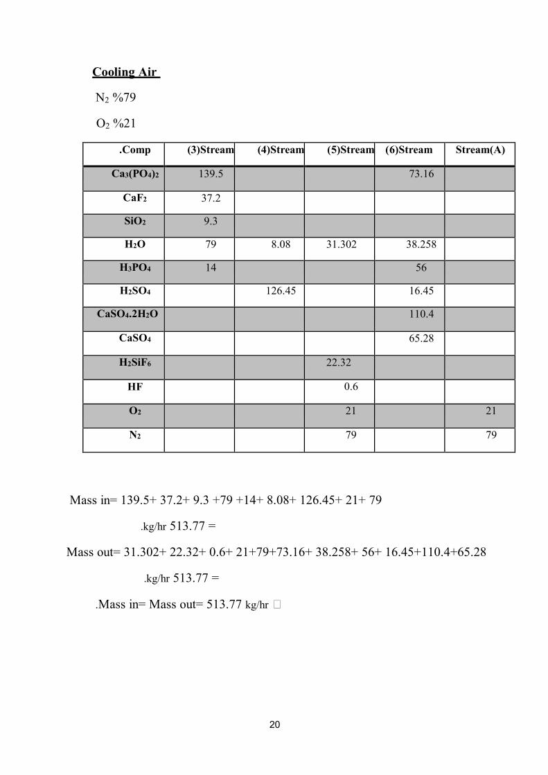
Cooling Air
N2 %79
O2 %21
Comp. Stream(3) Stream(4) Stream(5) Stream(6) Stream)A(
Ca3)PO4(2 139.5 73.16
CaF2 37.2
SiO2 9.3
H2O 79 8.08 31.302 38.258
H3PO4 14 56
H2SO4 126.45 16.45
CaSO4.2H2O 110.4
CaSO4 65.28
H2SiF6 22.32
HF 0.6
O2 21 21
N2 79 79
Mass in= 139.5+ 37.2+ 9.3 +79 +14+ 8.08+ 126.45+ 21+ 79
=513.77 kg/hr.
Mass out= 31.302+ 22.32+ 0.6+ 21+79+73.16+ 38.258+ 56+ 16.45+110.4+65.28
=513.77 kg/hr.
∴ kg/hrMass in= Mass out= 513.77 .
21
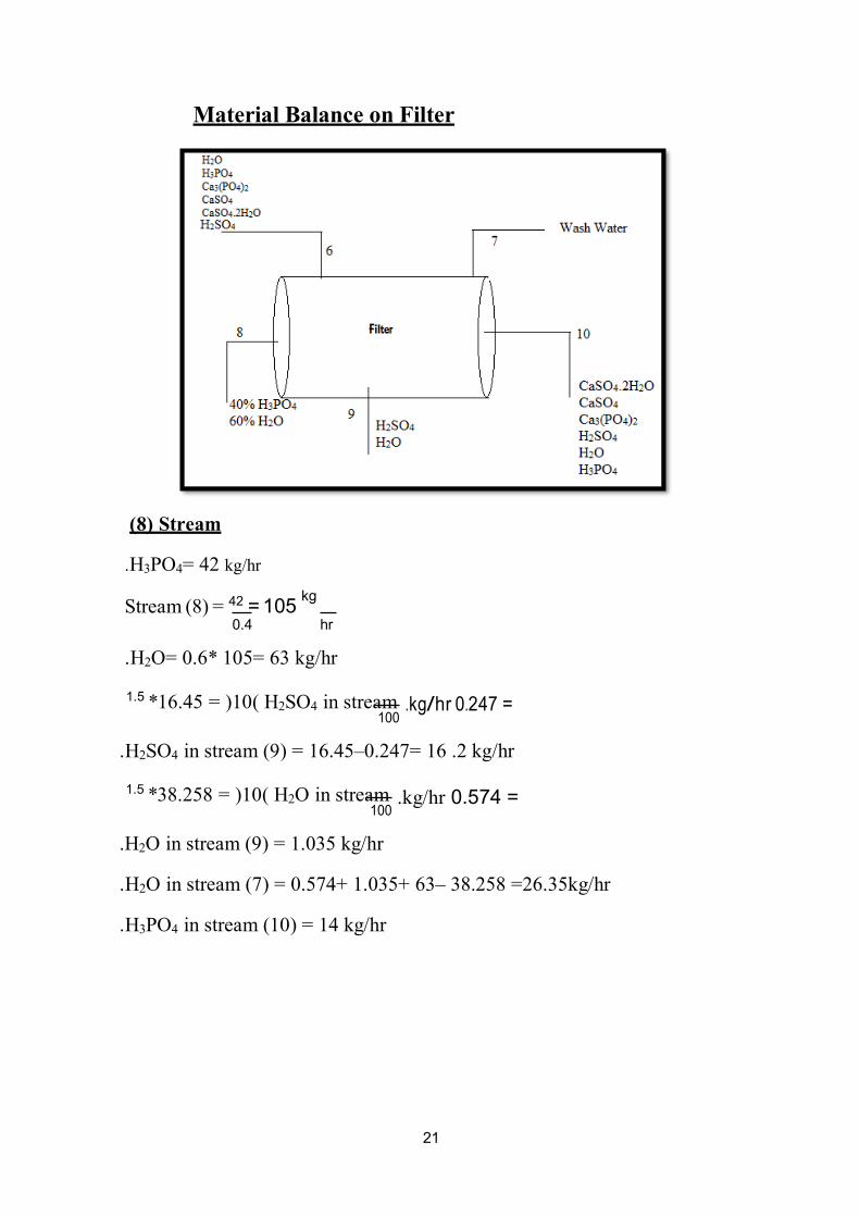
Material Balance on Filter
)8( Stream
.H3PO4= 42 kg/hr
Stream (8) = 42 = 105 kg
0.4 hr
.H2O= 0.6* 105= 63 kg/hr
1.5 *16.45 = )10( H2SO4 in stream
100
= 247.0 rh/gk.
.H2SO4 in stream (9) = 16.45–0.247= 16 .2 kg/hr
1.5 *38.258 = )10( H2O in stream 100
.H2O in stream (9) = 1.035 kg/hr
=0.574 kg/hr.
.H2O in stream (7) = 0.574+ 1.035+ 63– 38.258 =26.35kg/hr
.H3PO4 in stream (10) = 14 kg/hr

22
Comp. Stream(6) Stream(7) Stream(8) Stream(9) Stream(10)
Ca3)PO4(2 73.16 73.16
H2O 38.258 26.35 63 1.035 0.574
H2SO4 16.45 16.2 0.247
H3PO4 56 42 14
CaSO4.2H2O 110.4 110.4
CaSO4 65.28 65.28
- :Material Balance on Evaporator
M.B on H3PO4
IN = Out
0.4 42 = F Kg/hr F = 105.
.:Stream (8)
= 42 Kg/hr4 PO3H.
O = 63 Kg/hr2H.
.:Kg/hr14 = 49 –O in stream (11) = 63 2H.

23
Component Stream )8( Stream )11( Stream )12(
4PO3H 42 42
O2H 63 49 14
Mass In = 42 + 63 = 105 Kg/hr.
Mass Out = 49 + 42 + 14 = 105 Kg/hr.
.:Mass In = Mass Out = 105 Kg/hr.
.Material Balance on Mixing Tank
Component Stream )9( Stream )13( Stream )4(
4SO2H 16.2 110.25 126.45
O2H 1.035 7.045 8.08
Mass In = 16.2 + 1.035 + 110.25 + 7.045 = 134.53 Kg/hr.
Mass Out = 126.45 + 8.08 = 134.53 Kg/hr.
.:Mass In = Mass Out = 134.53 Kg/hr.
24
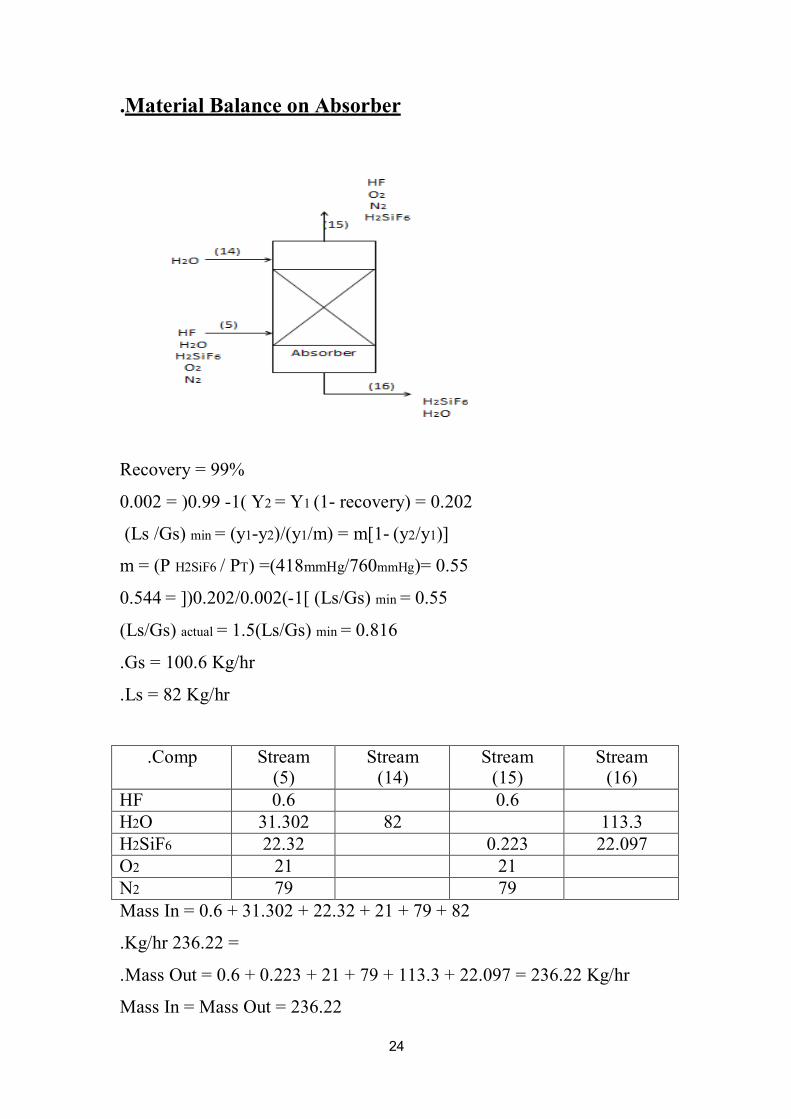
.Material Balance on Absorber
Recovery = 99%
recovery) = 0.202 -(11 = Y2 Y (1- 0.99 = )0.002
)]1y/2(y -m) = m[1/1)/(y2y-1= (ymin (Ls /Gs)
)= 0.55 mmHg760/mmHg) =(418TP /H2SiF6 m = (P
= 0.55min (Ls/Gs) [1-(0.002/0.202= ]) 0.544
= 0.816 min = 1.5(Ls/Gs) actual (Ls/Gs)
Gs = 100.6 Kg/hr.
Ls = 82 Kg/hr.
Comp. Stream )5(
Stream )14(
Stream )15(
Stream )16(
HF 0.6 0.6
O2H 31.302 82 113.3
6SiF2H 22.32 0.223 22.097
2O 21 21
2N 79 79
Mass In = 0.6 + 31.302 + 22.32 + 21 + 79 + 82
=236.22 Kg/hr.
Mass Out = 0.6 + 0.223 + 21 + 79 + 113.3 + 22.097 = 236.22 Kg/hr.
Out = 236.22Mass In = Mass

25
:Over all Material Balance
Stream Input Stream Output
Stream )1( 186
Stream )2( 93
(A) Stream 100
Stream )13( 117.295
Stream )7( 26.35 Stream )14( 82
Stream )10( 263.66
Stream )11( 49
Stream )12( 56
Stream )15( 100.823
Stream )16( 135.397
Mass In = 604.88 & Mass Out = 604.88
.:Mass In = Mass Out = 604.88 Kg/hr.
.General Diagram of Process
26
1
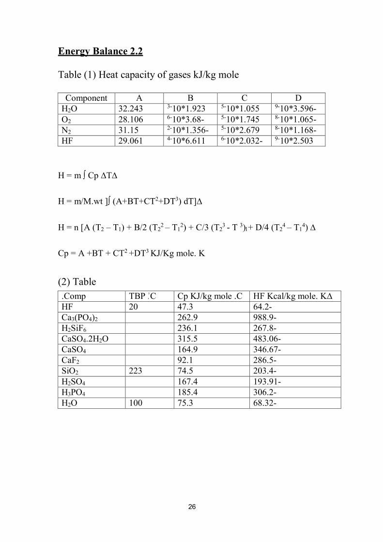
Energy Balance 2.2
Table (1) Heat capacity of gases kJ/kg mole
Component A B C D
H2O 32.243 3-10*1.923 5-10*1.055
9-10*3.596-
O2 28.106 6-10*3.68- 5-10*1.745
8-10*1.065-
N2 31.15 2-10*1.356- 5-10*2.679
8-10*1.168-
HF 29.061 4-10*6.611 6-10*2.032-
9-10*2.503
∆T∆Cp ∫ H = m
H = m/M.wt ]∫ (A+BT+CT2+DT3) dT]∆
H = n [A (T2 – T1) + B/2 (T2
2 – T12) + C/3 (T2
3 - T 3) + D/4 (T24 – T1
4) ∆
Cp = A +BT + CT2 +DT3 KJ/Kg mole. K
Table )2(
Comp. C. TBP Cp KJ/kg mole .C ∆HF Kcal/kg mole. K
HF 20 47.3 -64.2
Ca3(PO4)2 262.9 -988.9
H2SiF6 236.1 -267.8
CaSO4.2H2O 315.5 -483.06
CaSO4 164.9 -346.67
CaF2 92.1 -286.5
SiO2 223 74.5 -203.4
H2SO4 167.4 -193.91
H3PO4 185.4 -306.2
H2O 100 75.3 -68.32

27
Energy Balance on Reactor 2.2.1
Ca3 (PO4)2 HF
CaF2 (5) H2SiF6
SiO2 H2O
H2O O2 & N2
H3PO4
)3( 25
H2SO4
H2O 31
(6) H3PO4
H2O
Ca3 (PO4)2
H2SO4
CaSO4.2H2O
CaSO4
Cooling 25
Air (O2&N2)
)A(
:Reaction
Ca3 (PO4)2 + 3H2SO4 +6H2O →
2H3PO4 + 3(CaSO4.2H2O)
CaF2 + H2SO4 →
6HF + SiO2 →
2HF + CaSO4
H2SiF6 +2H2O
:Operating Conditions
80-= 75 T , 1atm P =. , Phase Liquid
Re
act
or

28
Heat in = heat out
M Cp ∆TCa3(PO4)2 + m Cp ∆TCaF2 + m Cp ∆TSiO2+ m Cp ∆T H2O + m Cp∆TH3PO4 + m Cp
TH2SO4∆
m Cp ∆TH2O + m Cp ∆TO2 + m Cp ∆TH2 + ∆Hr° = m Cp ∆T HF + m Cp ∆TH2SiF6 + +
mCp∆TH2O
m Cp ∆TO2 + m Cp ∆TN2 + m Cp ∆TH3PO4 + m Cp ∆TH2O + m Cp ∆TCa3(PO4)2 + m Cp +
+ TH2SO4∆
m Cp ∆TCaSO4 + m Cp ∆TCaSO4.2H2O + Q + m λ H2O
°T ref.. = 25C
M Cp HF ∆T + m Cp H2SiF6 ∆T + m Cp H2O ∆T + m Cp O2 ∆T + m Cp N2∆T + m Cp H3PO4
T + m Cp H2O ∆T + m Cp Ca3(PO4)2∆T+ m Cp H2SO4∆T+ m Cp CaSO4∆T+ m Cp∆
CaSO4.2H2O∆T+ Q + m λ H2O = ∆Hr°+ m Cp H2O ∆T + m Cp H2SO4∆T
We have three reactions:
∆KJ/Kg.mole2901.5 –Cal/g.mole = 693.5 –Hr°=
Hr2°= 5.34 Cal/g.mole = 22.343 KJ/Kg.mole∆
Hr3°= 184.16 Cal/g.mole = 770.5 KJ/Kg.mole∆
∆Hr°= 0.214 *)–2901.5 + (0.48 *22.342 +0.155 *770.5
∆KJ/Kg490.765 –Hr°=
0.6
20
∴10−4 ∴6.611 + (298 –353)29.061[ ∴
2 ∴ 6−10 ∴2.032
− (2982 − 3532) ∴ 3
+ (298 − 353) 32.243[ 31.302 + [ (2984 − 3534) ∴ 9−10 ∴2.503
+ (2983 − 3533) 4
5−10 ∴1.055 + (2982 − 3532) ∴
3−10 ∴1.923
18
∴ 9−10 ∴ 3.596
− (2983 − 3533) 2 3 4
](298 − 353) ∴ 0.67 [ ∴ 22.32
+ ](2984 − 3534) 144
5−10 ∴1.745 + (2982 − 3532)
6−10 ∴3.68 − (298 − 353) 28.106[
21 + − 3533)
32 2 3 8−10 ∴1.065
− (2983
4 − (298 − 353) 31.15[ ∴
79 + ](2984 − 3534)
28 2−10 ∴1.356
2
5−10 ∴2.679 + (2982 − 3532)
3
8−10 ∴1.108 − (2983 − 3533)
4 − 3534)
29
∴ 73.16
+ (298 − 353) 75.3 ∴ 38.258
+ (298 − 353) 185.4 ∴ 56
+ (2984 98 18 301
+ (298 − 353) 167.4 ∴ 16.45
+ (298 − 353) 167.4 ∴ 16.45
+ (298 − 353) 262.9 98 98
– = ∴ + 31.302
∴ 40683 + ](298 − 353) 236.1 ∴ 65.28
+ (298 − 353) 164.91 ∴ 110.4
172 136 18
(298 − 304) 167.4 ∴ 126.45
+ (298 − 304) 75.3 ∴ 8.08 + 490.765 18 98
KJ/hr263273.7493 –Q = .
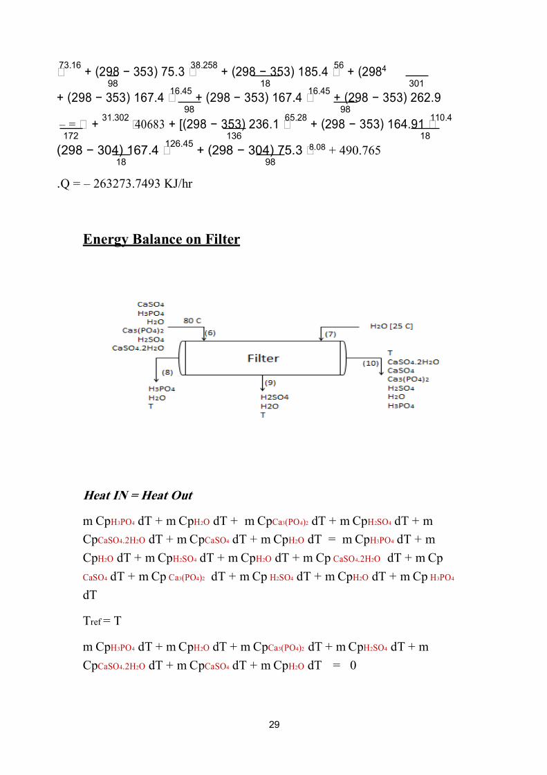
Energy Balance on Filter
Heat IN = Heat Out
m dT + 4 OS2HpC m + dT 2 )4PO(3aCpC + m dT O2HpC m + dT 4 OP3HCp m
m + dT 4 OP3HCp m = T d O2HpC m + dT 4 aSOCpC m + dT O2H2.4aSOCpC
Cp m + dT O2H2.4aSOC Cp m + dT O2HpC m + dT 4 OS2HCp m + dT O2HpC
4OP3H Cp m + dT O2HpC m + dT 4 OS2H Cp m + dT 2 )4OP(3aC Cp m + dT 4 aSOC
dT
= Tref T
m + dT 4 OS2HpC m + dT 2 )4PO(3aCpC m + dT O2HpC m + dT 4 OP3HCp m
dT O2HpC m + dT 4 aSOCpC m + dT O2H2.4aSOCpC = 0

30
Mixing tank
>> )]56/98 * (185.4 +)38.258/18 * (75.3 ) +73.16/310 * (262.9 +
)16.45/98 * (167.4 ) +110.4/172 * (315.5 ) +65.28/136 * (164.9 { [353 –
0 T{ = –T{ + [26.35 * 4.184] {298
T = 72 C°
:Energy Balance on mixing tank
H2O (13)
H2SO4
H2SO4 )9( )4( H2SO4
H2O 72) ( H2O
Heat in = Heat out
m Cp H2O ∆T + m Cp H2SO4 ∆T + m Cp H2O ∆T + m Cp H2SO4 ∆T= m Cp
H2SO4 ∆T+ m Cp H2O ∆T
Tref. = T
m Cp H2O ∆T + m Cp H2SO4 ∆T + m Cp H2O ∆T + m Cp H2SO4 ∆T = 0
]1.035/18 *75.3 )345 – T + )16.2/98 *167.4 (345-T[ + ])7.045/18 *75.3
)298-T + )110.25/98 *167.4 (298 – T = ])0
31 T= = K304
52 C

31
Energy Balance on Evaporator
Heat In = Heat Out
Q + dT O2HpC m + dT 4 OP3HCp m =
dT O2HpdT + m C4 OP3H+ m Cp O2HʎdT + m O2Hm Cp
= 72 Cref T°
dT O2HCp m + O2Hʎ m + dT O2HpC m + dT 4 OP3HCp m = Q
Q ( =42/98*)185.4(*345-373( + )14/18{*)4.184(*345-373 + )
)49/18*(32.243)*373-345) + (1.9238*10^-3/2)*(373^2-345^2 + (
)1.055*10^-5/3)*(373^3-345^3 (– )3.596 *10^-5 /4)* (373^4-345^4 + {(
)49/18 *(40683
Q = 115665.33 KJ/hr.
This heat is supplied by sat. Steam 150 C°
= 2113 KJ/Kgs ʎ.
= 115665.33/2113 = 55 Kg/hrs = Q/ʎs m.
32
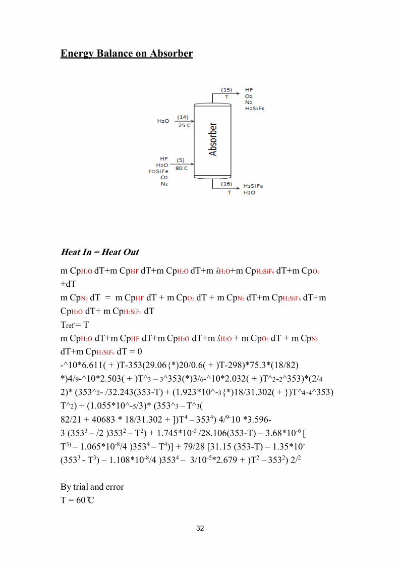
Energy Balance on Absorber
Heat In = Heat Out
2 OdT+m Cp6 SiF2H+m CpO2HʎdT+m O2HdT+m Cp HFdT+m Cp O2Hm Cp
dT+
+m Td 6 FSi2HCp m+Td 2 NpC m + dT 2 OpC m + dT FHpC m = dT 2 NCp m
dT 6 SiF2HCp + mTd O2HpC
= Tref T
2NpC m + dT 2 OCp m + O2Hʎ m+Td O2HCp +mTd HFpC m+Td O2HCp m
0 = Td 6 FiS2HCp +mTd
)82/18*(75.3*)298-T( + )0.6/20{*)29.06(353-T( + )6.611*10^-
4/2)*(353^2-2T^( + )2.032*10^-6/3(*)353^3 – 3T^( + )2.503*10^-9/4 *)
)353^4-4T^( + {)31.302/18{*)3-T) + (1.923*10^-32.243(353/ -22)* (353^
(3T^ –3 3)* (353^/5-) + (1.055*10^2T^
82/21 + 40683 * 18/31.302 + ])T4 – 3534) 4/9-10 *3.596-
3 (3533 – /2 )3532 – T2) + 1.745*10-5 /28.106(353-T) – 3.68*10-6 [
T3) – 1.065*10-8/4 )3534 – T4)] + 79/28 [31.15 (353-T) – 1.35*10-
(3533 - T3) – 1.108*10-8/4 )3534 – 3/10-5*2.679 + )T2 – 3532) 2/2
By trial and error
C0 6T =

33
CHAPTER THREE
EQUIPMENT DESIGN
Equipment Design On Reactor 3.1
Ca3 (PO4)2 HF
CaF2 (5) H2SiF6
SiO2 H2O
H2O O2 & N2
H3PO4
)3( 25
H2SO4
H2O
31 C
(6) H3PO4
H2O
Ca3 (PO4)2
H2SO4
CaSO4.2H2O
CaSO4
Cooling 25
Air (O2&N2)
)A(
Reactions:
Ca3(PO4)2 + 3H2SO4 + 6H2O 2H3PO4 +3(CaSO4.2H2O)
CaF2 + H2SO4 2HF + CaSO4
6HF + SiO2 H2SiF6 + 2H2O
Operating Conditions
80C –T= 75 °
P= 1atm
Re
act
or
34
_
Liquid Phase
8hr –τ = 4
We have three chemical reactions.
The reaction is exothermic and temperature is maintained constant by passing air
across the reactor.
continuous stirred tank reactorFor
V
° FA
XA
)rA _ (
=
Where:
V= volume of reactor (m3)
Ѵº = volumetric flow rate (m3/time)
FAº = molar rate of A (mole of A/time)
XA= conversion
space timeτ = V CA °
V
° XA CA
CA _ CA
= =
°
° FA
= _ ( )rA
= ° )rA (
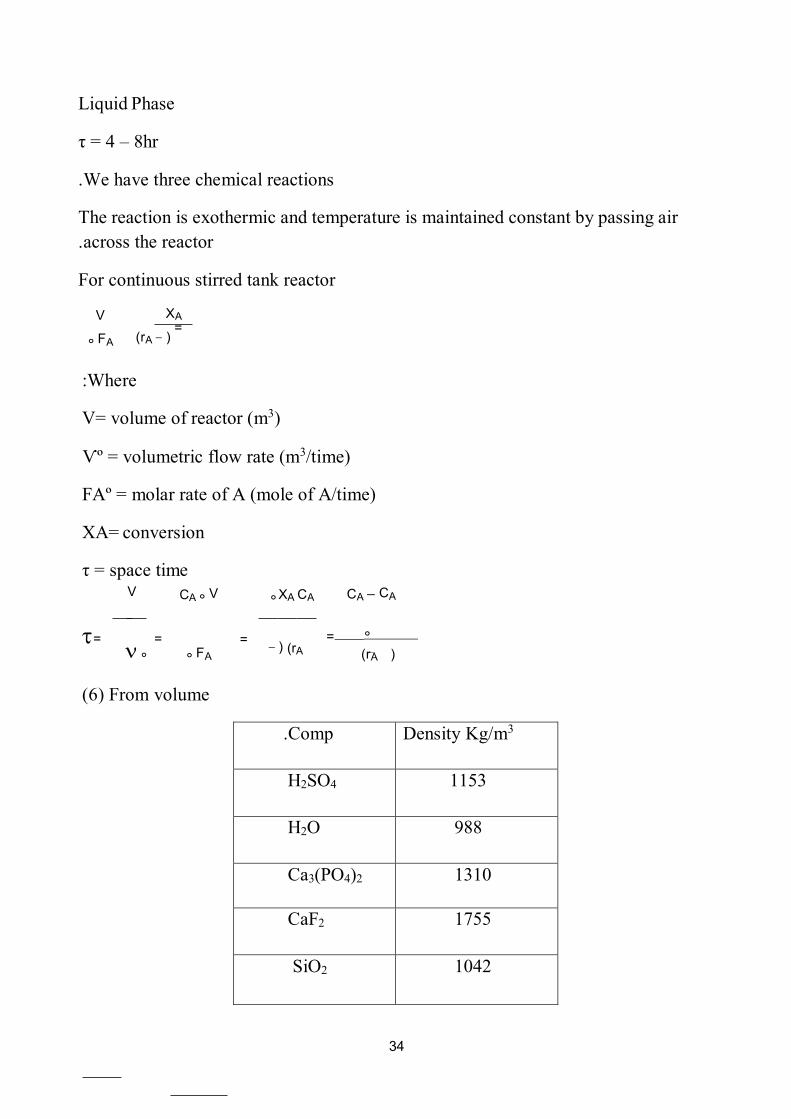
volumeFrom )6(
Comp. Density Kg/m3
H2SO4 1153
H2O 988
Ca3(PO4)2 1310
CaF2 1755
SiO2 1042
35
ρ mix = ∑ Xi ρi
Or
Ѵº = mass
∴
Where
Ѵº = volumetric flow rate (m3/hr).
density of component ρ =
.(kg/m3)
(kg/hr.)Mass= mass flow rate of component .
To find ρ mix V= mass ∴
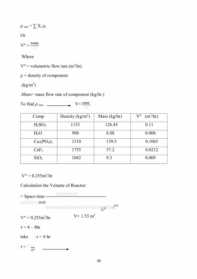
Comp. Density (kg/m3) Mass (kg/hr) Ѵº (m3/hr)
H2SO4 1153 126.45 0.11
H2O 988 8.08 0.008
Ca3(PO4)3 1310 139.5 0.1065
CaF2 1755 37.2 0.0212
SiO2 1042 9.3 0.009
.Ѵº = 0.255m3/hr
Calculation the Volume of Reactor:
= Space time ∴∴∴∴∴∴ ∴∴
∴∴∴∴∴∴∴ (m3)
∴∴∴∴∴∴∴∴∴∴ ∴∴∴∴ ∴∴∴∴ ∴∴ ∴∴∴∴∴∴∴(m3
hr
Ѵº = 0.255m3/hr.
8hr –τ = 4
take hr τ = 6.
τ = ∴ ∴
ºѴ
V= 1.53 m3
(
36
= 6 ∴
0.255
Volume of reactor = 1.53 m3 ∴

37
:Mechanical design for mixing vessel 3.1.1
D = ∴ 3
H = ∴
3
a = ∴
5
r = ∴
4
HL = d
b = ∴
10
Volume of feed = 1.53m3
Volume of feed in the reactor = Vf + 10% Vf
=1.53 +0.1 *1.53
m3 1.68 =
Volume of feed = ╥ d2 HL 4
38
HL = d
Volume of feed = ╥ d3
4
d3 ╥ = 1.53 d = 1.249m 4
D = 0.43m
H = 0.43m
a = 0.258m
r = 0.323m
HL = 1.249m
b = 0.13m
Height of reactor = 1.5m
1.5 * 2(1.249) ╥ = Volume of reactor = ╥ d2 H 4 4
2m3 ∴
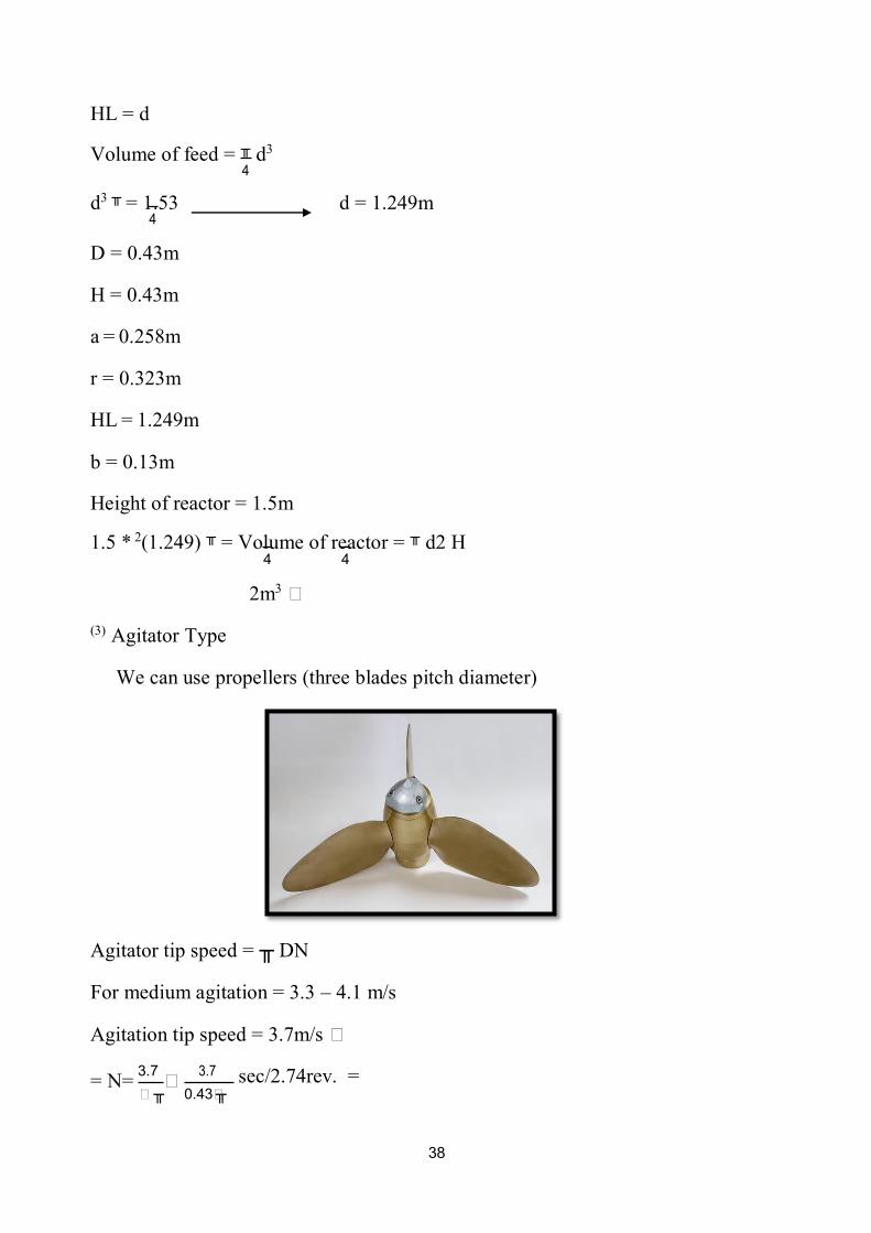
(3) Agitator Type
We can use propellers (three blades pitch diameter)
DN╥ Agitator tip speed =
m/s4.1 –For medium agitation = 3.3
∴ Agitation tip speed = 3.7m/s
= N=
3.7 ∴
3.7 =rev. 2.74/sec ╥ ∴ ╥ ∴0.43

39
The power required for mixing
NP = C (NRe)m (NFr)n
Where:
= NP = power number
P
N3 D5 P
NRe =
N D2 P
N2D
Number Froude = NFr = P
ρ mix = 1283.8Kg/m3
µmix = 0.065mNs/m2
2.74∴ 2(0.43)∴ N Re =
1283.8
3−10∴ 0.065
∴ Turbulent flow P
K2 N3 D5ρ =
For propeller
K2 = 0.32
106 ∴ 10 =
P = 0.32 * (2.74)2 * (0.43)5 * 1283.8
P = 125W
Mechanical Design:
Thickness of the vessel can be obtained using the following equation ]7[
e = ∴∴ ∴∴
∴−∴∴2∴
Where:
+∴
e = thickness of vessel (mm)
Pi = internal pressure (N/mm2)
(mm) Di = internal diameter
40
f = design stress
085 –J= joint factor = 0.8
allowance = 2mmC = corrosion
The stainless steels are the most frequently used corrosion resistant
materials in the chemical industry.
To impart corrosion resistance, the chromium content must be above 12
percent,
is the alloy to and the higher the chromium content, the more resistant
corrosion in oxidizing conditions. Nickel is added to improve the
oxidizing environments-corrosion resistance in non
typical design stress of stainless steel materials (18Cr/ 8Ni)
(4) at 80Cº = 160N/mm2
operating pressureDesign pressure = 10% above
=atm + 0.1*1atm = 1.1atm1
mm2/0.11N =
e = 0.11∴1.249 ∴ 103 2 ∴160
∴0.8 −0.11 +2 =3mm ∴mm 2.6
- :(5) Weight of Vessel
WV = CV ╥ ρ m D m g (HV + 0.8Dm) t * 10-3
Where:
etc… of the shell, excluding internal fittings, WV = total weight .
CV = a factor to account for the weight of nozzle manways, internal
etc…supports.
Can be taken as 1.15
HV = height or length between tangent lines (the length of the cylindrical
section m.(
sst = wall thickne
ρ m = density of vessel material

41
D m = mean diameter of vessel = (Di + t * 10-3) m
For steel vessel equation reduce to
WV = 240 CV D m (HV + 0.8Dm) t
WV = 240 * 1.15 * D m (1.5 + 0.8Dm) * 2.6 * 10-3
D m = (1.29 + 2.6 * 10-3) = 1.293m
WV = 240 * 1.15 * 1.293 (1.5 + 0.8 * 1.293) 2.6 * 10-3
KN2.5∴WV = 2.35KN
Weight of Insulation:
Thickness = 75mm
Mineral wool density = 130 kg/m3
t HVd ╥ Approximate volume of insulation =
0.5m3 = 3-10 * 75*1.5*1.29 * ╥ =
0.638KN Weight = 0.5 * 130 * 9.81 = 638N =
Double this to allow for fittings, etc. = 1.3KN= 1.5KN
Weight of vessel filled with water = ∴ D2LρH2O*g = 20KN 4
Weight of two man = 75 * 2* 9.81= 1.5kN
Total Weight:
Vessel = 2.5 kN
Insulation = 1.5
Vessel with water = 20
1.5 Two men =
+ WW + Wi + W man Wt = WV
=2.5 +20 +1.5 +1.5
=kN25.5
42
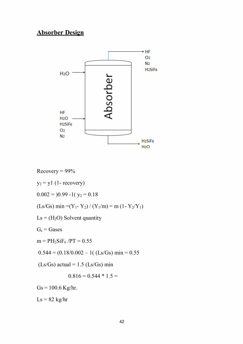
Absorber Design
Recovery = 99%
y2 = y1 (1- recovery)
0.002 = )0.99 -1( y2 = 0.18
(Ls/Gs) min =(Y1- Y2) / (Y1/m) = m (1- Y2/Y1)
Ls = (H2O) Solvent quantity
Gs = Gases
m = PH2SiF6 /PT = 0.55
(Ls/Gs) min = 0.55 (1 – 0.002/0.18 = (0.544
(Ls/Gs) actual = 1.5 (Ls/Gs) min
=1.5 *0.544 =0.816
Gs = 100.6 Kg/hr.
Ls = 82 kg/hr

43
∴2
Y = mx
Y = 0.55 x
The equilibrium data is linear
Calculation The Tower Height
ˉ∴ =
∴∴
KoG a . Pt ∫
∴1 .
∴∴
∴−∴∴
NOG Z = HOG.
∴∴ ∴∴∴ =
∴∴. ∴. ∴∴∴
1∴
∴∴∴ =∫
2∴
∴∴
∴ − ∴ ∴
Where;
Z= The Tower height
∴∴∴∴ ∴∴∴∴∴∴∴∴ ∴∴ ∴ℎ∴∴∴ℎ= ∴∴∴
NOG= Number of transfer unit
Y = 0.55 X
∴∴∴ =
1
1 − ɸ ln ](1 − ɸ(
∴
1
∴
2
+ɸ]
∴∴∴
= ɸ ∴∴
0.55 ∴ 100.6 = ɸ
82 0.675 =
1
0.18
∴∴∴ =
1 − 0.675 (0.675 − 1(] ln
0.002 +0.675]

44
NOG = 10.5 m.

45
Calculation the Area of column
Vapor Liquid
Flow 1.2575 4.56 kg mole /hr.
Density (6) 1.0 (7) .kg mole /hr 998
M.Wt 29 18 mole /hrkg .
Viscosity (8) 3-10 *0.02 (9) N.S/m2 3-10*0.89
Select 13 mm ceramic INTA lox Saddles
Packing factor (Fp) = 660
ԝ∴ ∴ ∴∴ ∴∴∴ = ∴ԝ ∴
√∴∴
∴∴∴ = 0.043 = 1.03
√ 4.56
= 3.47 998
(10) Design for pressure drop of 20mm H2O / m Packing
K4 = 0.77
At flooding K4 = 3.25
Percentage flooding = √0.9
5
=48.6 %
4∴ = ∴∴∴)
µ∴ (0.1∴)∴∴∴(2∴42.9 ∴∴
)∴∴−∴∴(∴∴
[ . …11]
2(∴∴∴(0.1(3−10∴0.406
)∴92∴ 42.9 = 0.77 998
(1.03−998) 1.03
V w* = 0.597 kg/m2. S
Column area required = 0.028 / 0.597 = 0.047 m2

46
= 24.5 cm ~0.25 m
Area = π/4 d2 = π/4 (0.25)2 = 0.049 m2 ؞
Packing Size to column = 0.25 / 13*10-3 = 19.2
Percentage Flooding at Selected diameter
=48.6 ) *0.047 /0.049 = (47 %
Estimate of HOG
Use cornrlls method
DL= 0.143 * 10-6 m2/s (10)
Dv=1.5 *10-5 m2/s (10)
µV= 0.02*10-3 Ns/m2
(Sc)v = µv/ρv .Dv =( 0.02*10-3 / 1.03 * 1.5 * 10-5 ) = 1.3
(Sc)l = µl/ρl .Dl = (0.89 *10-3/ 998 * 0.143*10-6) = 6.24
Lw* = 1.368 / 0.049*60 = 0.46 Kg/m2.s
at 47% flooding (11) K3=0.98
(12) at 47% flooding Ѱn = 52
(13) at Lw*, φh = 0.042
HL= 0.305 φh (Sc)L0.5 K3 (Z/3.05)0.15
Where :-
HL= height of liquid phase transfer unit, m
(11.43) φh = HL factor from fig
(Sc)L= liquid Schmidt number
(14) K3= percentage flooding correction factor from

47
Z= column height, m
HL = 0.305 * 0.042 * (6.24)0.5 *0.98*(10.5/3.05)0.15
HL = 0.038 m
[14]...… HG= 0.011 Ѱn (Sc)v0.5 (Dc/0.305)1.11 (Z/3.05)0.33 / (Lw* f1f2f3)
0.5
Where :-
HG= height of a gas phase transfer unit, m
n = HG factor from figѰ )11.42(
Dc= column diameter (m)
F1= liquid viscosity correction = (µL/µw)0.16
F2=liquid density correction = (ρw/ρL)1.25
F3= surface tension correction factor = (δw /δL )0.8
As the liquid temperature (25 °c) and the liquid is water
HG= 0.011 * 52 * (1.3)0.5(0.25/3.05)1.11(10.5/3.05)0.33 / (0.46*1.0)0.5
HG= 0.09 m
OG= HG+ m(Gm/Lm) HLH
HOG= 0.09+ 0.55( *100.6/82 * )0.037
HOG= 0.115 m
Z = HOG. NOG
Z= 0.115 * 10.5
Z= 1.2 m
Close enough to the estimate value.

48
1 1
1
Pressure drop
Re1= ρ u dm / µ
Where
U1 = U/e
e) µ-dm = e/s(1
can use this equationto find the pressure drop we :-
∴1 =
∴∴2
∴∴ ∴3
∴(1 − ∴)∴
∴∴2
∴1 =
∴∴2
5 0.4
∴∴ +
∴∴0.1
e = 0.476
ρ = 1.0 Kg/m3
Volumetric flow rate = cross sectional area * velocity
100.6/1.0 =0.049 *u
U = 2053.06 m/s
d particle = 13mm
for spherical particle
S= 6/d = 6/0.013 = 461.5 m2/m3
µ = 0.02 * 10-3 Ns/m2
424491 = 10-3*0.02* )1-0.476(Re1 = 1.0 *2053.06/ 461.5
∴1
∴∴2
5
424491 =
0.4
4244910.1 +
=0.109
0.109 = ∴∴ 0.4763
2053.06 ∴ 1.0 ∴ 12.8 ∴ (0.476 − 1)461.5
dp = 128.34 KN/m2
49
Mechanical Design Thickened of
Column from volume (6) e = (Pi Di/
C Pi) +-f2
where
e = thickness of column (mm)
Pi= design pressure (N/mm2)
Di= internal diameter (mm)
F = design stress (N/mm2)
C= corrosion allowance = 2 mm
typical design stress of stainless steel material (18 Cr / 8 Ni) at 70 °c =
[15] .…… N/mm2 160
pressure Design =10 %pressure above operating
atm = 0.11 N/mm2 1.1 = 1 * 1.1 =
mm 2.4 0.11( + 2 = –e = (0.11*1200 / 2*160 ~2.5 mm
Design of domed end
From volume 6 use standard ellipsoidal
= ∴ ∴∴ ∴∴
−0.2∴∴2∴∴
Where
+∴
head (mm) e = thickness of
0.85 –J = joint factor = 0.8
∴ = 0.11 ∴ 1200
2 + 0.11 ∴ 0.2 − 160 ∴ 0.85 ∴ 2

50
e = 2.1 mm ~ 2 mm
Nozzles
0.35-ρd = 226 G0.5
where
d= pipe diameter (mm)
G= mass flow rate (kg/s)
ρ= density (kg/m3)
feed gases
G= 0.043 Kg/s
ρ= 997.04 Kg/m3
d= 226 (0.023)0.5 (997.04)-0.35 = 3.05 mm
feed water
G= 0.023 kg/s
ρ= 998 kg/m3
0.35 = 3.1 mm-d= 226 (0.023)0.5 (998)

51
Evaporator Design 3.3
H2O
)11( 001 C
Steam 051 C
051 C
Feed 27 C
H2O (8)
H3PO4
100 C
H2O
H3PO4
Component Steam )8( kg/hr.
Steam )11( kg/hr.
Steam )12( kg/hr.
H3PO4 42 42
H2O 63 49 41
Calculation of Bundle tubes
take tube dimensions as follows (15) :-
d 61 =﮿ mm
mm di = 14
L = 1.5 m (16) Heat flux = 2012.5 w/m2
From Energy Balance
)12(
52
Heat load = 32.3 Kw
flux Q/Heat = area transfer Heat ؞
A= 32.3/2.0125 = 16 m2
L = ᴨ *14*10-3 *1.5 = 0.066 m2 ﮿ᴨ d = ﮿Area of one tube a
Number of tube
a/A = N 342 = .61/6600 =﮿
Tubes arranged in triangular pitch one pass
Pt = 1.25 d﮿
Pt = 1.25*16 = 20mm
From volume (6) eq. (12.3b) P. (649)
[Nt/K1]1/n1 ﮿Bundle diameter Db = d
(17) Where K1, n1 constants
K1 = 0.319
N1 = 2.142
Db = 16 [243/0.319]1/2.142 = 355 mm
Tube side pressure drop
051 = matesof uretperameT C
From steam table ѵg = 1.13 m3/kg
ρ g = 1/ѵg = 1/1.13 = 0.885 Kg/m3
flow area of
At = Nt (ᴨ/4 di2)
At = 243 * ᴨ/4 *(14*10-3)2 = 0.0374 m2
Mass flow rate G = ρ *ut *At
G = 0.016 kg /s , ρ = 0.88 Kg/m3
Ut = G/ ρ *At = 0.016/0.885*0.0374 = 0.53 m/s
Steam viscosity ɱ = 1.4*10-5Ns/m2
442.5 = 10-5*1.4 /)10-3*14(*Ret = ρ*ut*dt/ɱ = 0.885*0.5

53
(18) jf = 2*10-2 friction factor
(19) P = Np*[ 8*jf*(L/d) *(ɱ/ ɱw)-m + 2.5] * ρ*ut2/2∆
Where:
Np = number of passes
Jf = fraction factor
L = tube length (m)
di = inside diameter (m)
ρ = density (Kg/m3)
ut =velocity (m/s)
neglect (ɱ/ ɱw)-m = 1
P= [ 8*2*10-2 *(1.5/14*10-3) +2.5] *0.885 * (0.5)2/2 = 2 N/m2∆
Psia 4-10*2.9 =
pressure drop must choose the other dimensions of the tube to -If a high
(1Psia) get to the proper pressure drop is less than

54
Volume of evaporator (20) V = 1.7261[ e -p/RT + K (ɱl/ɱv)
0.2]
Where:
V= volume of evaporator (m3)
P= pressure of evaporator (N/m2)
R= gas constant
T= temperature (K)
K= constant depend on type of tubes bundle (steam bundle)
vertical tubeK= 2.125 for
K= 1.1942 for horizontal tube
μv= 1.4*10-5 Ns/m2
μl = 0.28*10-3Ns/m2
tube take horizontal
operating pressure = 10 psi = 0.6 atm. = 0.69*105 N/m2
V = 1.7261[ e-0.69*10-5/8.314+373 + 1.1942(0.28/0.014)0.2] = 5.5 m3
select shell diameter = 1.5 m For standard tubes diameter
)bundle shell diameter must be equal to tube length of steam(
Length of evaporator
V= ᴨ/4 D2 *L
ᴨ/4 (1.5)2 *L L = 5.5
=3.114 m = 3.2 m
Calculation of residence time )Ԏ(
ѵ/v= Ԏ﮿
Where:
V = volume of evaporator (m3)
feed volumetric flowrate (m3/s) = ﮿ѵ
ѵ/v= Ԏ﮿ = 5.5 ∴/∴∴∴∴
Ρmix. = 1333.6 Kg/m3
=Ԏ 5.5
42∴105/6.3133 =2.9 hr. = 174 min
55
Mechanical Design
=t ∴∴∴∴∴
∴−∴∴2∴
where:
(21) ∴ +
t= thickness of shell (mm)
Pi = operating Pressure (N/mm2)
Di= shell diameter (mm)
J = joint factor )0.8(
C= corrosion allowance (2mm)
f= design stress (N/mm2)
Operating pressure = 10% above design pressure = 1.1*0.069= 0.076
N/mm2
(22) Stainless steel (18cr/8Ni)
f= 150 N/mm2
=t 1500∴0.076
2∴0.8∴150−0.076 +2 =2.5 ∴∴3= ∴∴
Thickness of cover
We can use hemispherical cover thickness of cover = 0.6 * thickness of
shell
= 1.8mmt = 0.6 *3
Weight of evaporator
For stainless steel
Wv = 240 Cv Dm (Hv+0.8 Dm)t
Where
Cv= constant )1.08(
Dm= mean shell diameter (m)
(Di + t * 10-3 )= 1.503 m =
H= length of vessel (m)
t = shell thickness (mm)
5145 N Wv= 240 * 1.08 * 1.503 (3.2+ 0.8 * 1.503) * 3 =
56
Weight of vessel filled with water
Ww = ᴨ/4 D2L * ρH2O * g
=5.5 *1000 *9.81 =53955 N
Weight of tubes
Weight of tube (1.05 Kg/m)
Weight of one tube = 1.5 * 1.05 = 1.6 Kg
N Weight of tube (Wt) = 243 *1.6 * 9.81 = 3815
Weight of cover
ri = D/2 = 1.5/2 = 0.75 m
r﮿ = m 18750. = 18000.+ 75.0 = +t ir
m 4.7 = 0.7518 * 2 + 3.2 = evaporator of height Total ؞
Volume of sphere (4ᴨ/3 *r3 )
2(ri – 3﮿r) volume of two cover = 4ᴨ/3 ؞
for carbon steel (ρ = 7.7*10-4 Kg/m3)
9.81*104*7.7* [2(0.75) – 2)0.7518([Wc= 4ᴨ/3
=8549*2 =17098 N

57
CHAPTER FIVE
SELECTION PLANT LOCATION AND SITE
The location of the plant can have a crucial effect on the profitability
of project, and the scope for future expansion. Many factors must be
considered when selecting suitable site, and only a brief review of the
principal factors will be given in this section.
1. area Location, with respect to the marketing
2. supply Raw material.
3. Transport facilities.
4. labor Availability of.
5. power utilities: water, fuel,Availability of .
6. land Availability of suitable.
7. disposal Environmental impact, and effluent.
8. considerations Local community.
9. Climate.
10. Political and strategic considerations.
Safety and Environmental
obligation to safeguard the health Any organization has a legal and moral
and welfare of its employees and the general public. Safety is also good
business; the good management practices needed to ensure safe operation
will also ensure efficient operation
financial the being loss the term, insurance an is ”prevention loss“ term The
loss caused by an accident. This loss will not only be the cost of replacing
damaged plant and third party claims, but also the loss of earnings from
opportunity lost production and lost sales.
chemical in but hazardous, extent some to are processes manufacturing All
processes there are additional, special, hazards associated with the
of aware be must designer The conditions. process the and used chemicals
application these hazards, and ensure, through the
nd engineering practice, that the risks are reduced to acceptable of sou
levels.
Safety and loss prevention in process design can be considered under the
following broad headings:
1. hazards Identification and assessment of the.

58
2. hazards: for example, by containment of flammable and Control of the
materials toxic.
3. Control of the process. Prevention of hazardous deviations in process
variables
(Pressure, temperature, flow), by provision of automatic control systems,
interlocks,
ther with good operating practices and managementAlarms, trips; toge.
4. Limitation of the loss. The damage and injury caused if an incident
pressure occurs:
fighting equipment-relief, plant layout, provision of fire.
THE HAZARDS (toxicity, reviewed are chemicals of hazards special the section this In
chemical of hazards other the with together corrosively); and flammability
plant operation
1. Toxicity Most of the materials used in the manufacture of chemicals are
inherent the on depend will hazard potential The extent. some to poisonous,
exposure toxicity of the material and the frequency and duration of any.
2. Corrosion and erosion: despite good design and materials selection,
some corrosion problems may arise, both internally and externally. The
rate depends on the anticipated corrosionfactor to be applied .
3. Explosions an explosion is the sudden, catastrophic, release of energy,
fire, without occur can explosion An wave). (blast wave pressure a causing
of pressure-such as the failure through over
air receivera steam boiler or an
4. Temperature deviations Excessively high temperature, over and above
and failure structural cause can designed, was equipment the which for that
disaster initiate a.
5. systems deluge-water failure, structural against protect to protection Fire
fire are usually installed to keep vessels and structural steelwork cool in a
6. Noise
Excessive noise is a hazard to health and safety. Long exposure to high
noise levels can cause permanent damage to hearing
7. hazard arising from the Rotating equipment: this factor accounts for the
use of large pieces of rotating equipment: compressors, centrifuges, and
some mixers.
8. Leakage joints and packing: this factor accounts for the possibility of
seal leakage from gaskets, pump and other shaft

59
Economic The economic construction and efficient operation of a process unit
will depend on how well the plant and equipment specified on the process
sheet is laid out-flow
The principal factors to be considered are:
1. costs tingEconomic considerations: construction and opera.
2. requirements The process.
3. operation Convenience of.
4. maintenance Convenience of.
5. Safety.
6. expansion Future.
7. construction Modular.
)23( The cost of the devices used in the factory
The cost of a reactor height of (1.5 m) = 30,000 $
$ The cost evaporator area (16 m2) = 20,000
The cost of absorbing high tower (12.8 m) = 55,000$
Total = 105,000 $
factory note that "these accounts by plans in place for the year 2004

60
1. Wikipedia
REFERENCES
2. "1987 , March 2,Chemical and Engineering NewsPhosphoric Acid",
- , American Institute of Chemical Sulfuric/Phosphoric Acid Plant Operation
Engineers, New York, 1982.
3. From volume (6) fig 10.75 we have viscosity and volume we get suitable is
diameter) (three blades pitchpropellers
4. 13.2 From volume (6) table
5. From volume )6(
6. From Ideal Gas Law (p v = n R T)
7.Antoine.Frostburg.edu/chem/sense/javascript/water- density.html
8. tables/substances/water-Viscopedia.com/viscositywww./
9. www.engineersedge.com/physics/water_density_viscosity_specific_w
eight_13146.htm
10. https://en.m.wikipedia.org./wiki/Thermal_diffusivity
11. From volume (6) fig )11.41(
12. volume (6) figFrom )11.42(
13. From volume (6) eq. )11.111(
14. From volume (6) fig )11.41(
15. From volume (6) table (12.3) p. )645(
16. Dangler From "Heat transfer mechanism of vaporization water" by
17. from volume (6) p. (649), Table (12.4 )
18 .667) (P.From volume (6) fig. (12.24)
19. 668) from volume (6) (P.
20. Using brooks and badger equation "from heat transfer mechanism of
dangler vaporization water " by
21. Thickness of evaporator shell from volume )6(
22. From volume (6) table )13.2(
23. From volume (6) fig.(6.3a) & fig. (6.5a) page. )256(

61
24. Graduation Project / University of Technology Faculty of Engineering /
Chemical Engineering Department for the academic year 2005