PHILIP W. MANSON •DALTON G. MILLER
16
Station Bulletin 426 May 1954 PHILIP W. MANSON •DALTON G. MILLER
Transcript of PHILIP W. MANSON •DALTON G. MILLER

Station Bulletin 426 May 1954
PHILIP W. MANSON •DALTON G. MILLER

Aggregates and Cement.
Maximum Mixing Water ...
Compaction of Materials .
Tile Curing .
CONTENTS
Water Spray at Prevailing Temperatures.
Saturated Steam at Temperatures under 212 F ..
Curing Temperatures
Length of Curing Period ...
Special Soil Considerations .
Tile of Superior Quality for Acid Soils ...
Chemistry of Cement for Sulfate Exposure
Conclusions ..
Appendix ..... .
Page
4
6
8
10
10
10
11
12
13
13
13
14
14

Making
DURABLE CONCRETE DRAIN TILE
on Packer-Head Machines
WITH AN APPENDIX REGARDING SUPPORTING STRENGTHS OF DRAIN TILE
Philip W. Manson and Dalton G. Miller1
FEW CONCRETE PRODUCTS are exposed in service to a wider range of conditions than drain tile. The conditions may range
all the way from highly favorable to extremely severe, sometimes in the same drainage system. Therefore, drain tile of good quality should always be installed when long, satisfactory service is desired.
To define some of the physical properties meriting the term "good quality" the American Society for Testing Materials adopted in 1914 the first Standard Specifications jo1· Dmin Tile, serial designation C4-14. This has been revised a number of times and now has the ASTM designation C4-50T, the T indicating that in their present form the specifications are tentative.
The principal requirements of these specifications are for crushing strengths and water-absorption limits of tile oven-dried at 230 to 248 F. and then boiled for five hours. Two classes of drain tile are designated-"standard" and "extra-quality." The requirements for each class of concrete tile are shown in table 1. Drain tile meeting these requirements, it must be noted, are not
necessarily safe against cracking in ditches wider or deeper than ordinary. In the appendix to this bulletin may be found allowable depths (calculated) of installation for tile of various diameters in ditches of various widths.
Tile of the smaller diameters that will consistently meet these ASTM requirements can be made on the "packerhead" machines in common use if certain manufacturing provisions are established and maintained. These are (1) well-graded sound aggregates and sufficient cement, (2) maximum of mixing water, (3) ample compaction of the materials, and ( 4) adequate curing. In addition, tile manufacturers must take special measures to produce tile that will endure in soils of high acidity or high sulfate content.
1 This paper is based on studies conducted by the department of agricultural engineering at the University of Minnesota in cooperation with the division of waters. Minnesota State Department of Conservation. Graduate School funds were allocated for assembling this material. The authors are professor and research associate, respectively, in agricultural engineering.

4 MINNESOTA STATION BULLETIN 426
Table I. Physical Test Requirements lor Two Classes of Concrete Drain Tile
Standard drain tile Extra-quality drain tile
Maximum Maximum average average
Internal Minimum average absorption by Minimum average absorption by
diameter crushing strength 5-hour boiling crushing strength 5-hour boiling
test test of tile
3-edge sand 3-edge sand bearing bearing bearing bearing method method method method
pounds pounds pounds pounds inches per per per cent per per per cent
linear linear linear linear foot foot foot foot
4 800 1,200 10 uoo 1.600 8 5 800 1.200 10 1,100 1.600 8 6 800 1.200 10 1,100 1.600 8
800 1.200 10 l.lOO 1.600 8
10 800 1.200 10 uoo 1,600
12 800 1,200 10 1,100 1,600 8 15 870 1.300 10 1,100 1,600 8
18 930 1.400 10 1,200 1.800
21 1.000 1,550 10 1.400 2,100
24 l.l30 1.700 10 1,600 2.400
27 !.230 1,850 10 1,800 2,700
30 !.330 2,000 10 2,000 3,000 8
33 !.430 2,150 10 2,200 3,300 8
36 !.530 2,300 10 2,400 3,600 8
42 1,730 2,600 10 2,800 4,200
Aggregates and Cement
THE AGGREGATES should conform to the general requirements of
Standard Specifications for Concrete Aggregates, ASTM designation C33. Because the fines necessary for workability will be largely supplied by the cement of the rich mixes from which high-quality drain tile are made, the proportion of the sand passing the 100-mesh sieve need not be more than the 2 per cent minimum stipulated in C33. Somewhat more than this probably will not affect the strength of the tile but will increase its absorption, judging from tests of nearly 2000 cylinders made at the University of Minnesota. These cylinders were made mostly of 1-3 mixes, using aggregates with only a
trace passing the 100 mesh sieve and adding or substituting different finely divided products in proportions which ranged from 2% to 66 per cent of the weight of the cement. Several of the admixtures were used with 2, 3 or more portland .cements with about the same results for each. It would seem, therefore, to be poor practice to add an excess of fine sand in order to obtain tile with especially smooth (slick) surfaces.
For all practical purposes the essentials of good grading for drain tile of the smaller diameters may be expressed briefly in this way: not much less than 40 per cent retained on the No. 8 sieve with preferably somewhat more than half of this 40 per cent retained on the

DURABLE CONCRETE DRAIN TILE 5
'l"o. 4 sieve. Without a high proportion u.~ these coarser particles in the mix it will be extremely difficult to produce drain tile which will be low enough in absorption to meet the requirements of ASTM C4-50T. The effects on absorption of variations in the aggregate gradation are shown by the tests recorded in table 2.
At best, the proportion of the coarser particles in aggregates suitable for thinwalled tile of the smaller diameters will always be lower than that which theoretically would produce maximum strength. The mixes and aggregate combinations of table 3 are essentially those used at a number of Midwest plants which manufacture satisfactory drain tile. The weights of the aggregates are those of surface-dry materials. Note that the mixes for extra-quality and standard tile differ chiefly in that the proportion of both cement and pea gravel are increased for extra-quality tile. It is difficult to manufacture drain tile of the smaller diameters which will be consistently high in strength and low in absorption unless they are made with rich mixes, even though the aggregate grading is as coarse as recommended.
Table 3. Examples of Suitable Mixes for Drain Tile
Standard Drain Tile
Sizes 5 to 8-inch 94 lbs. Cement
Concrete sand .. Pea gravel .
. ........................... 265 lbs. 68 lbs.
(Mix is I to 31/z by weight)
Extra-quality recommended for sizes 10-inch and larger.
Extra-quality drain tile
Sizes 5 to 8-inch Cement Concrete sand . Pea gravel .....
(Mix is I to 3 by weight)
Sizes 10 to 12-inch Cement Concrete sand Pea gravel.
(Mix is 1 to 3 by weight)
94 lbs. . .. 210 lbs.
73 lbs.
94 lbs. !88 lbs. 94 lbs.
Once the mix has been determined that produces tile which meet strength and absorption requirements, the yield in the number of tile of the same size per batch becomes a measure of uniformity of output. On the basis of the mixes of table 3, the maximum yield in foot-long tile per sack of cement may be expected to be about as shown in table 4.
Table 2. Concrete Drain Tile Quality as Related to Aqqreqate Gradation•
Crushing strengths (Sand bearing method) Absorption Sieve analyses of aggregates
Extra Standard Below Extra Standard Below Sieve Extra Standard Below quality quality standard quality quality standard No. quality quality standard
pounds per linear foot per cent per cent coarser 1,570 1,450 1,100 6.0 9.4 11.6 31<! 0 0 0 1,550 1,300 1,300 5.9 9.1 10.3 3fs 0 1,620 1.270 I.IOO 6.9 9.4 11.0 4 26 20 1,880 1,370 990 5.7 10.1 11.5 8 40 34 12
2,210 1,270 810 6.3 9.9 14.1 16 50 45 26
1,890 1,690 1,090 6.1 9.1 11.3 30 62 58 56
1,450 1.340 1,140 5.8 10.0 11.9 so 86 84 88
2,220 1,050 100 97 97 98
1,490 5.9 10.1 12.1 1,740 1,080 6.2 11.3 residue 3 3 2 1,650 1.230 5.8
Average Average fineness 1.780 1.400 1,090 6.1 9.6 11.7 I modulus 3.6 3.4 2.8
• The tests recorded here were made on tile of nominal wall thickness with inches in extra-quality tile and six inches in standard and below-standard tile.
diameters of four

6 MINNESOTA STATION BULLETIN 426
Table 4. Yield in Foot-Long Tile of Various Dimensions per Sack of Cement ~-------------~--- ~- ------------------ -~----------
Diameter Wall thickness
inches inch
5 9/16
6 5/8
8 3/4
10 7/8
12
Approximate air-dry weight
per foot
pounds
10
14
22
31
45
Standard quality
Extra quality
feet of tile per sack
41 36
31
19
27
17
12
8\12
Maximum Mixing Wate1·
THE TEMPTATION in making drytamped concrete products where the
jackets (forms) are stripped immediately is not to use enough water in the mix, so that the products will have no tendency to stick to the jackets or slump out of shape when the jackets are removed. However, making dry-tamped concrete drain tile with too little water in the mix means making products whose quality will be lower than the richness of the mix makes possible.
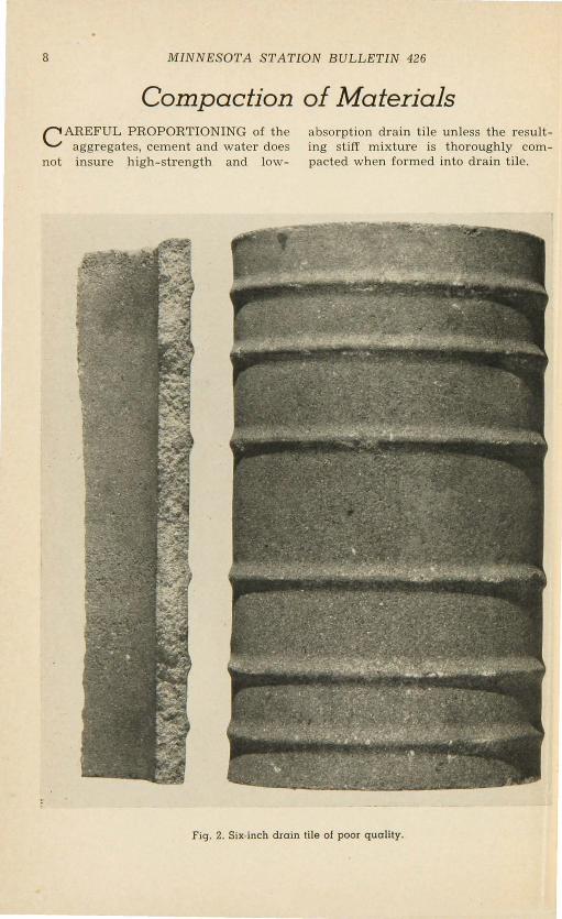
When the mix is too dry the tile surface on the outside will be relatively smooth. Maximum quality is indicated when this outer surface has the stippled appearance caused by a wetter mix sticking slightly to the jacket when it is removed. Figure 1 shows the appearance of tile made with well-graded aggregates and sufficient mixing water; figure 2 shows the appearance of poor quality tile made with a dry and greatly over-sanded mix.
It may be said that the total amount of mixing water, including any surface moisture in the aggregates, will not exceed about three and one half gallons per sack of cement. However, it serves little useful purpose to express the quantity of mixing water on the accepted basis of gallons per sack of cement, for the margin between the
proper amount and too little is very narrow in making tile of the smaller diameters on packer-head machines. In practice, the useable water will be largely determined by the man at the mixer according to the apparent workability of each batch.
Most tile manufacturers rely on the mixer man to gauge the consistency of the mix. He usually does this by noting the way the material falls off the revolving blades of the mixer or the way a handful behaves when squeezed into a ball or by its stickiness when rubbed on a smooth metal plate. An intelligent and experienced man can thus determine the proper amount of mixing water with a high degree of accuracy. Even so, some manufacturers consider it desirable to install measuring devices which accurately control the amount of water added to a batch. Of course, such devices must be adjusted frequently because the moisture content of the aggregates varies from time to time. The devices are no substitute for the experience of a capable mixer man and a desire on the part of the manufacturer to get the highest possible quality out of his material.
The amount of water in the mix which will produce tile of the highest strength and lowest absorption, other

DURABLE CONCRETE DRAIN TILE
Fig. l. Six-inch drcrin tile of good quality.
factors b ing the same, may be slightly in excess of that which will mak for the maximum output by the m achin . Satisfactory production schedules are
maintained, however, at plants where til are consistently mad with close to the maximum amount of mixing wat r .
7
8 MINNESOTA STATION BULLETIN 426
Compaction of Materials c AREFUL PROPORTIONING of the
aggregates, cement and water does not insure high-strength and low-
absorption drain tile unless the resulting stiff mixture is thoroughly compacted when formed into drain tile.
Fig. 2. Six-inch drain tile of poor quality.

DURABLE CONCRETE DRAIN TILE 9
Drain tile of the smaller diameters are usually made on a power-driven machine with a vertical shaft on the lower end of which is attached a heavy metal cylinder assembly called the "packer head." It consists essentially of a "packer ring" or " troweling ring" on which are bolted adjustable "packer cheeks." The packer head, r evolving at speeds of 300 revolutions per minute or higher, rises as it r evolves and its cheeks compact the surrounding mixture firmly against the jacket as they shape the inside of the tile. A view of a packer-head assembly for six-inch tile is shown in figure 3.
Packer-head tile machines have been in use for more than 40 years and are now made by a number of manufacturers. While this type machine was designed originally to make tile of the smaller diameters, packer-head machines are now available which make pipe 24 inches and larger in diameter and up to 6 feet long. Though the principle is the same for all machines of this type, the compaction of the materials will not be adequate unless the machine is well designed, built for hard service and amply powered, and the packer cheeks are kept in proper adjustment.
The packer cheeks are designed to extend 1/ 32 to 1/ 16 inch outside the packer ring. They compact and trowel the inside of the tile as the head assembly revolves while passing vertically through the tile. The sand and gravel mix is highly abrasive and the cheeks wear rapidly until they become flush with the surface of th packer ring, at which time the ring starts to drag and wear. The cheeks may require resetting after making anywhere from 200 to 800 six-inch tile and will ordinarily need to be r enewed somewhere between 3000 and 6000 tile.
If proper attention is given to ·setting the cheeks, the packer ring may give satisfactory service up to 18,000 tile. Wear on both cheeks and packer ring
• Fig. 3. Packer ring and packer cheeks used to form the inside of machine-made
6-inch concrete drain tile.
will be least when the mix is wettest. Wear may be increased somewhat as the mix is coarsened although manufacturers seem to agree that dryness of the mix is much more responsible for excessive wear than is coarseness, at least within the limits of coarseness feasible for tile of the smaller diameters.
The great importance of compaction in relation to strength and absorption of concrete made of a stiff mix is illustrated by the graph of figure 4. Data for this graph are from tests of cylinders of mixes suitable for drain tile. The cylinders were identical in a ll respects except that their tamping was purposely varied all the way from slight to excessive. Note that the compressive strengths ranged from highs in excess of 6000 pounds per square inch to lows of 1200 psi and that absorptions ranged from lows under 5 per cent to highs in excess of 13 per cent (figure 4, page 10) .

10 MINNESOTA STAT ION BULLETIN 426
Tile Curing ALL CONCRETE drain tile should be
moist-cured in accordance with good practices so that previous to installation they will meet the ASTM strength and absorption requirements.
Sati:'?factory methods for the moist curing of concrete tile are of two distinct types: (1) water-spray or fog at the temperatures which prevail and (2) saturated steam at temperatures which may be anywhere between 100 and 190 F.
WATER SPRAY AT PREVAILING TEMPERATURES
In the early days of the industry it was customary to cure drain tile by hand sprinkling, for the most part after they had been stockpiled in the yard. With the advent of curing shelters it became the practice to fog -cure for a day or two, relying on the heat evolved by the cement as it sets and hardens
7000
·~ 6000
.c t;. ~ 5000
"' " ·~ 4000
"' c.
; 3000 (.)
>-0
;' 2000
"' N
0
1\ "' 0
\ 0
0~ 00~
0 I"- 0
........ loco
1'- 0
~ 0
0
1000 3 5 7 9 II 13
Fig.
AbsorptiOn of 28 days (Boiling), per cent
4. Correlation between strength absorption of 2-by-4-inch cylinders
tamped to produce different degrees of compaction.
~ 15
and
to keep the tile from freezing during the moderately cool weather of spring and fall. Following the curing period under cover, the tile were usually sprinkled by hand or through an overhead system for two or three days or more after stockpiling.
Moist curing of this type when con-· tinued long enough during favorable weather is adequate but is not feasible in cold weather. On the whole, it is slow from a production standpoint because concrete requires time as well as the presence of moisture to attain a fair proportion of its potential 28-day strength in even moderately cool weather. Other conditions being identical, it may be assumed that drain tile cured continuously at 33 F. for any period up to 28 days will be only twothirds as strong as tile cured at 72 F., and tile cured at 50 F. will be only five-sixths as strong. On a time basis it means that in order to have equal strengths at early ages tile cured at 72, 50 or 33 F. will require moist-curing periods as follows:
Curing time required at three temperatures for equal strength concrete.
72 F . 2 days 3 days
41/z days
50 F. 3 days 5 days 8 days
33 F. 7 days
13 days 25 days
SATURATED STEAM AT TEMPERATURES UNDER 212 F.
It has become a common practice in the manufacture of concrete drain the to supply both moisture and heat during the initial curing period through the medium of low-pressure steam. The primary reason for using low-pressure steam is to accelerate strength gains at early ages. Results in this respect are

DURABLE CONCRETE DRAIN TILE 11
entirely satisfactory with the exception that when steamed too soon after making, the concrete may be permanently weakened and may have higher absorption.
It is the rule to use boilers which operate under low pressures of 5 to 25 psi but from here on there are many variations in the steaming process. For instance, no effort is made at some plants to hold the curing temperatures above 75 F. while at other plants the temperatures are not allowed to fall below 150 F., once the steaming has begun, and may run as high as 175 F. much of the time. The length of time the tile are steamed while in the curing rooms may range from over night to four days or longer.
When concrete products of any kind are cured with saturated steam it will be difficult to maintain the desired temperatures in the curing rooms unless they have tight fitting doors and have walls and ceilings with good heat retention characteristics. Without proper attention to these details, heat losses will be high and the steaming operation reduced in effectiveness through loss of moisture around the doors and by condensation as the steam comes in contact with the cold wall and ceiling surfaces.
The size of the curing room in relation to the volume of concrete cured is also important because, other factors being the same, it will make for more uniform curing and be more economical to steam-cure in rooms no larger than necessary to accommodate a day's run of tile. At present, there is no uniformity in the size of curing rooms; some may have floor space of only 300 or 400 square feet and may be but 7 feet high, while others may have 3000 or 4000 square feet and have heights of 15 feet or more. Even with well constructed and relatively small curing rooms, it will be more economical and more satisfactory to provide auxiliary
heat in cold weather rather than depend entirely on the steam used for moist-curing. This is done at many plants either by steam heating systems or by preheating the rooms with portable stoves (salamanders).
Lacking at most tile plants which use low-pressure steam for curing are regulators. In fact not many tile plants even have in the curing rooms thermometers that can be read when the doors are closed. The ideal equipment would be automatic controls which regulated both temperature and humidity of the room. Good results could also be achieved with automatic tEOmperature and humidity recorders, even though controls were operated manually.
Although methods are far from standardized, there are certain procedures which have been determined by laboratory studies and manufacturing experiences to be basically sound when lowpressure steam is employed for curing drain tile.
CURING TEMPERATURES
Solely from the standpoint of strength, nothing is gained by elevating the curing temperatures much above 170 F. In fact, there may be a definite slowing down in strength gains, if not actual loss of strength, around 190 F. On the other hand, the rate of gain from 100 to 170 F. is quite steadily proportionate to temperature.
The effects on strength of curing experimental cylinders in water at room temperatures and in steam at 100, 155, and 212 F. are shown in table 5 based on tests at the University of Minnesota. The water-cured cylinders were tested wet while those cured in steam were stored in room air after steaming and tested dry.
Based on these and similar tests reported by a number of workers, it ap-

12 MINNESOTA STATION BULLETIN 426
Table 5. Compressive Strengths at 7 Days of Water-Cured and Steam-Cured Cylinders
Time cured after 24 hours in moist closet
6 hours
24 hours
4 days
6 days
27 days•
• 28 day test•
Water at temperature
72 F.
4,090 psi
5,760 psi
pears that a temperature of 155 F., plus or minus 15 degrees, is as high as necessary in a curing room when drain tile are cured with saturated steam, strength alone considered.
LENGTH OF CURING PERIOD
As shown in table 1, ASTM crushing strength requirements for drain tile up to 12 incres in diameter are 1200 pounds per linear foot for standard tile and 1600 pounds for extra-quality tile on the basis of the ASTM sand-bearing method. These requirements are not unduly severe, since the compressive strength of the concrete in the shell of even extra-quality tile need not be much in excess of 4000 psi to produce the stipulated tile strengths. Therefore, when proper attention has been given to the other details of manufacture, curing in steam around 155 F. can be of relatively short duration. There is a question, though, whether it should be reduced to an overnight operation, as practiced at a number of plants. It would be much better from the standpoint of a completed operation to lengthen this curing period by another 24 hours.
Many tests have shown that concrete is weakened if steam at a temperature above 100 F. is allowed to come in con-
Steam at temperatures
100 F. 155 F. 212 F.
3,660 psi 4.370 psi 3,420 psi
4,440 psi 4,770 psi 4,120 psi
4,780 psi 5,510 psi 4,770 psi
tact with it the first 12 hours after making. While 12 hours may be longer than feasible, it would seem that at least 6 hours should be allowed for drain tile to harden before subjecting them to steam at 155 F. Perhaps for the first 6 hours only enough steam should be used to insure a humid condition in the curing room and, unless the room is otherwise heated, to keep the temperature between 75 and 100 F. At the end of 6 hours the temperature can be raised with reasonable safety to the full 155 F. This temperature should be maintained for a minimum of 30 hours before the steam is turned off.
Handled in this manner the entire curing operation will be completed by early morning of the second day after the tile are made and there will have been no damaging volume changes caused by temperature fluctuations during the first 36 hours. It is doubted that adequate steam-curing at 155 F. can be effectively accomplished in a much shorter period. When the curing is shortened to overnight, the initial 6-hour hardening period is usually cut to about 2 hours, steaming to some 8 or 10 hours, and cooling to an hour or so. Drain tile cured by the longer and more thorough method are likely to be somewhere around 15 per cent stronger than any cured by the shorter process.

DURABLE CONCRETE DRAIN TILE 13
Special Soil Considerations TILE OF SUPERIOR QUALITY
FOR ACID SOILS
Chemically, any portland cement is a base and certain constituents of the cement in drain tile will react with the acids present in some soils. The extent of the action will depend principally on the degree of soil acidity and the permeability of the tile walls. Therefore, any concrete tile installed in defi- -nitely acid soils should be "extraquality" or better.'
A definitely acid soil may be considered to be one with a value that approaches 6.0 on the pH scale commonly used and generally found to be satisfactory to express the effective acidity of a soil. When this value drops much below 6.0 a soil is usually considered to be markedly acid.
The proportion of the cornbelt area which has subsoils with a pH not far above 6.0 is by no means insignificant From the standpoint of long-time service, this is ample reason for installing only well-made concrete tile in all drainage systems.
CHEMISTRY OF THE CEMENT FOR SULFATE EXPOSURE
Where concrete tile are exposed to soils which carry an excess of about 3,000 parts per million (0.30 per cent) of sodium or magnesium sulfate, singly or in combination, special precautions should be taken. It is in the field of cement chemistry where by far the greatest progress has been made in improvement of the performance of concrete exposed to the action of soil sulfates. The importance of the chemistry of the
cement has been shown many times and standard specifications have been prepared for sulfate-resistant portland cements in both the United States and Canada.
The essential provisions are maximum limitations on the percentage of the potential compound tricalcium aluminate (3Ca0·Al,Oa), commonly abbreviated (C,A). From many tests it can be concluded that for highest resistance the iron-alumina ratio should be not far below 1.0 and the calculated C,A content should not exceed 5.5 per cent" The following ASTM specifications (designation C-150) cover cements which are sulfate-resistant to different degrees, type V being the one which was designed specifically for this purpose:
Type V is for use where high sulfate resistance is required; this cement limits the CaA content to 5.0 per cent. Type IV is a cement of low heat of hydration and has considerable sulfate resistance, limiting the C,A content to 7.0 per cent. Type II cement is for use where moderate sulfate resistance is required; the C:~A is limited to 8.0 per cent. While 8.0 per cent is too high for a true sulfate-resistant portland cement it is preferable to a cement without any C,A limitation. Type II cement is the only one of the three that is usually stocked, while types IV and V are of the nature of special and large-order cements. Frequently a Type II cement with a C,A content of 6 per cent or below can be purchased in the open market, in which case it will have the advantage of availability as a sulfate-resistant product of a high order without added trouble or expense.
2 See Durabi!·ity of Concretes and Mortars in Acid Soils, with Particular Reference to DTain Ti!e. Minn. Agr. Expt. Sta. Tech. Bul. 180.
3 See Long-Time Tests of Concretes and Mortars Exposed to Sulfate Waters. Minn. Agr. Expt. Sta. Tech. Bul. 194.

14 MINNESOTA STATION BULLETIN 426
Conclusions CLEARLY certain provisions and
procedures in the manufacture of smaller-diameter drain tile on packerhead machines will make for higher tile strength, lower absorption, and greater durability. This summation of them is based chiefly on current manufacturing experience at different tile plants located in the upper Midwest. While there may be differences of opinion regarding the details of nearly all the procedures outlined, perhaps the great-
est differences will be in connection with aggregate gradation and with curing practices in relation to effectiveness at early ages. In particular, the effects of different proportions of the finer aggregate particles on both strength and absorption of drain tile is a disputed matter. Studies based on additional data are planned to clarify both of these phases of concrete drain tile manufacture.
Appendix MANY TESTS have been made, par-
ticularly at Iowa State College, to determine experimentally and theoretically the loads to which drain tile are subjected in service. These tests look to design of tile systems in which undue cracking of the tile from overloading after installation may be avoided. The effects of numerous factors have been studied, such as soil type, depth of cover, width of trench and bedding conditions of the tile as laid. Based on these studies, table 6 has been prepared to show safe allowable depths of trench for drain tile of diameters from 5 to 24 inches installed in thoroughly wet clay at 120 pounds per cubic foot in trenches of the widths indicated. The depths presume "ordinary bedding" conditions as defined in the text which follows and illustrated in figure 5.
"Ordinary bedding" is that in which the under side of the tile is carefully bedded in soil for 60 to 90 degrees of the circumference, with the ditch bottom suitably rounded and the tile blinded
to a depth of at least 0.5 foot above the top of the tile, using care to fill the space at the sides of the tile with top soil. This type of bedding is assumed to be simulated when tile are tested by the "sand bearing method" of table 1. It is on this basis that the load factor for ordinary bedding is presumed to have a value of 1.0. In the case of "impermissible bedding" the supporting strength of the tile is reduced to a degree indicated by the load factor of 0.7, a loss of 30 per cent. The supporting strength of the tile may be increased 20 to 30 per cent by laying in accordance with "first class" conditions, whereas tile laid in the "concrete cradle bedding" will have supporting strengths 100 per cent in excess of those for ordinary beqding.
First-class bedding should always be aimed at where the load on the tile is calculated to be moderately higher than normal. The most favorable load factor of 1.3 for this bedding will be obtained when the tile are laid on granular material (road gravel or crushed rock)

DURABLE CONCRETE DRAIN TILE
IMPERMISSIBLE BEDDING LOAD FACTOR = 0.7
0.68c
FIRST CLASS BEDDING LOAD FACTOR =1.2 -1.3
0.5 Be
ORDINARY BEDDING LOAD FACTOa = 1.0
. Bd ..
CONCRETE CRADLE BEDDING (PLAIN)
LOAD FACTOR :. 2.0
Fig. 5. Types of trench beddings.
15

16 MINNESOTA STATION BUL!JETIN '426
in an earth foundation shaped to fit the lower part of the tile exterior for a width equivalent to at least 60 per cent of the outside width of the tile. The remainder of the tile should then be entirely surrounded to a height of at least one foot above its top by this granular material packed to fill completely all spaces under and adjacent to the tile. This fill should be tamped thoroughly on each side and under the tile
as far as practicable in layers not to exceed six inches in thickness . It is doubted that this tamping can be adequately accomplished except with power tampers. If top soil is substituted for the granular materials, the load factor will be reduced from 1.3 to 1.2, a reduction in supporting strength of 8 per cent. It will not be practicable to use sticky clay subsoil in the manner recommended for first-class bedding.
Tile Size
5"
6"
8"
10"
12"
IS"
18"
21"
24"
ASTM Class
Standard Extra quality
Standard Extra quality
Standard Extra quality
Standard Extra quality
Standard Extra quality
Standard Extra quality
Standard Extra quality
Standard Extra quality
Standard Extra quality
Table 6. Allowable Drain Tile Depths (See Notes Below)
Crushing Strengths Width of Trench-Inches
pounds per linear foot 18" 20" 22" 24" 26"
1.200 8.7 7.5 7.5 7.5 7.5 1,600 Inf. 12.2 9.5 9.5 9.5
1.200 8.8 6.8 6.6 6.6 6.6 1,600 In f. 12.3 8.7 8.4 8.4
1,200 9.0 7.0 5.8 5.4 5.4 1.600 In f. 12.5 8.8 7.3 6.9
1,200 9.2 7.2 6.0 5.3 4.9 1,600 Inf. 12.7 9.0 7.5 6.6
1,200 9.4 7.3 6.2 5.5 5.0 1.600 Inf. 12.9 9.2 7.7 6.8
1,300 8.6 7.1 6.3 5.8 1,600 13.1 9.5 8.0 7.1
1,400 7.0 6.5 1,800 9.6 8.5
1,550 2,100
1.700 2,400
28" 30" 36"
7.5 7.5 7.5 9.5 9.5 9.5
6.6 6.6 6.6 8.4 8.4 8.4
5.4 5.4 5.4 6.9 6.9 6.9
4.9 4.9 4.9 6.0 6.0 6.0
4.7 4.7 4.7 6.1 5.6 5.6
5.2 4.9 4.7 6.3 5.8 5.2
5.9 5.5 4.7 7.5 6.9 5.7
6.7 6.2 5.0 9.3 8.3 6.8
7.1 5.9 10.0 7.9
Notes: (I) Values given for the various trench widths are depths of trench in feet. (2) Crushing ·strengths given are averages in pounds per linear foot based on sand·
bearing method, Specifications for Drain Tile, ASTM designation C4·50T. (3) These values allow a safety factor of 1.5. (4) Width of trench is measured at top of tile. (5) Loadings were computed for wet clay soil at 120 lbs. per cubic foot. Somewhat greater
depths are permissible for lighter soils. (6) Ordinary pipe laying whereby the under side of the tile is well bedded on soil for 60
to 90 degrees of the circumference. (7) Int. indicates infinity.