Phased array innovations for 5G mmWave beamforming · Phased array innovations for 5G mmWave...
59
Phased array innovations for 5G mmWave beamforming Alberto Valdes-Garcia Research Staff Member, Manager Master Inventor & Member IBM Academy of Technology IBM Research T. J. Watson Research Center
Transcript of Phased array innovations for 5G mmWave beamforming · Phased array innovations for 5G mmWave...

Phased array innovations for 5G mmWave beamforming
Alberto Valdes-GarciaResearch Staff Member, ManagerMaster Inventor & Member IBM Academy of Technology
IBM ResearchT. J. Watson Research Center

©2015 IBM Corporation2
Toronto 5G Summit – November 2015
Enabling 5G: mmWave Silicon Integration and Packaging
https://ieeetv.ieee.org/ieeetv-specials/toronto-5g-summit-2015-bodhisatwa-sadhu-enabling-5g-mmwave-silicon-integration-and-packaging?
mmWave WLAN – IBM 16-Element 60-GHz phased array
mmWave Backhaul – IBM 64-Element 94-GHz phased array
mmWave handset radio – IBM 60-GHz low-power TRX
Overview of IBM Research’s 10+ years of
work on silicon-based mmWave radios,
phased arrays, and Gb/s link
demonstrations

©2015 IBM Corporation3
Seattle 5G Summit – November 2016
mmWave Radio Design for Mobile Handsets
https://ieeetv.ieee.org/conference-highlights/seattle-5g-mmwave-radio-design-for-mobile-handsets?
mmWave handset radio – IBM 60-GHz low-power TRX
60-GHz (802.11ad), low-power (<250mW
TX or RX), 32nm SOI CMOS TRX with
switched beam antenna for wide spatial
link coverage

©2015 IBM Corporation4
Introduction to Millimeter-Wave (mmWave)
Wavelength (m)
Frequency (Hz)
1m 10cm 1cm 1mm 0.1mm 10um 1um 0.1um 10nm 1nm 0.1nm 0.01nm
300M 3G 30G 300G 3T 30T 300T 3x10¹⁵ 3x10¹⁶ 3x10¹⁷ 3x10¹⁸ 3x10¹⁹
mic
row
ave
Te
rah
ert
z
AK
A: F
ar
Infr
are
d
Infr
are
d
Ultra
vio
let
X-r
ays
vis
ible
mmWave
mmWave is defined as 30-300 GHz, or l=10 mm to 1 mm
Higher Frequency
(1) More Bandwidth
(5% @ 60 GHz = 3 GHz)
(5% @ 6 GHz = 0.3 GHz)
(2) Smaller Wavelength
• Integrate antenna in package
•Greater resolution radar/imager
• Directional propagation
Current applications:
-Gb/s short-range comm.-Automotive radar-Mobile backhaul-Airport security-5G
Key advantages of mmWave for 5G are higher data rates and
spatial multiplexing

©2015 IBM Corporation5
Gb/s mmWave Wireless Links:Applications across the infrastructure stack
mmWave-based 5G network concept:
Ericsson: E. Dahlman, et al., “5G Radio Access,” Ericsson Review, June, 2014
Samsung: W. Roh, et al., "Millimeter-wave beamforming as an enabling technology for 5G cellular communications:
theoretical feasibility and prototype results," in IEEE Communications Magazine, Feb, 2014

©2015 IBM Corporation6
4 in.
Discrete 60-GHz Radio World’s 1st monolithic mmWave RadioIBM Research 2006
Cost: $1,500
Size: 10’s of cm
Cost: ~$15
Size: <10 mm
Enabling technology #1: Silicon integration of mmWave transceivers
Miniaturization and mass adoption of mmWave applications

©2015 IBM Corporation7
Beam steering acheived by
varying delay in each
element
t
2t
3t
4t
With N element TX, if each element radiates P Watts,
Effective radiated power in target direction: N2.P Watts.
Enabling technology #2: Integrated phased arrays for beam forming
Delay
4t
4t
4t
4t
Lower interference
due to incoherent
addition of signals.
Higher power at
targeted receiver due
to coherent addition of
signals.d=l / 2
=
l
t
c2sin 1
c.t = d.sinθ
A. Natarajan, et al., JSSC 2005
©2015 IBM Corporation8
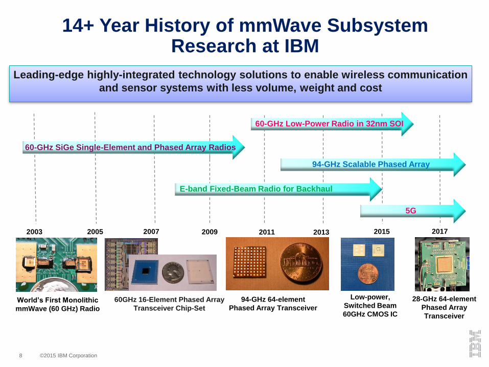
94-GHz 64-element
Phased Array Transceiver
14+ Year History of mmWave Subsystem Research at IBM
60GHz 16-Element Phased Array
Transceiver Chip-Set
Leading-edge highly-integrated technology solutions to enable wireless communication
and sensor systems with less volume, weight and cost
World’s First Monolithic
mmWave (60 GHz) Radio
Low-power,
Switched Beam
60GHz CMOS IC
20112005 20132003 2007 2009 2015
60-GHz Low-Power Radio in 32nm SOI
60-GHz SiGe Single-Element and Phased Array Radios
94-GHz Scalable Phased Array
E-band Fixed-Beam Radio for Backhaul
5G
2017
28-GHz 64-element
Phased Array
Transceiver

©2015 IBM Corporation9
This Presentation: Reston, VA 5G Summit – August 2017
Phased array innovations for 5G mmWave beamforming
• 28-GHz Phased Array Antenna Module co-developed by IBM and
Ericsson
• Focus of this presentation is on innovative techniques to enable
precise beamforming
• IC Architecture
• Building blocks to enable orthogonal phase and amplitude control
at each RF Frintend
• Antenna-in-package implementation
TX H/TX V

©2015 IBM Corporation10
Key 5G mmWave Challenges
Maximize TX range while minimizing
form factorEasy to control
Fine beam steering resolution
Support simultaneous
beams
Key challenges

©2015 IBM Corporation11
Key 5G mmWave Challenges…… to IC Design Challenges
Maximize TX output power, with TX/RX integration
Orthogonal phase and gain control
Fine phase resolution
Support for two polarizations
Key IC challenges

©2015 IBM Corporation12
IC Architecture: RF Phase Shifting(single polarization shown for simplicity)
5.2GHz
LO
3GHz
TX IF
3GHz
RX IF
B. Sadhu, et al, "A 28GHz 32-Element Phased-Array Transceiver IC with Concurrent Dual Polarized
Beams and 1.4 Degree Beam-Steering Resolution for 5G Communication", IEEE ISSCC, 2017.

©2015 IBM Corporation13
IC Architecture: LO Path
5.2GHz
LO
3GHz
TX IF
3GHz
RX IF
21GHz
10GHz
10GHz

©2015 IBM Corporation14
IC Architecture: TX Path
5.2GHz
LO
3GHz
TX IF
3GHz
RX IF

©2015 IBM Corporation15
IC Architecture: RX Path
5.2GHz
LO
3GHz
TX IF
3GHz
RX IF

©2015 IBM Corporation16
IC Architecture: Front-End
To
antennaTo
split
ter/
com
bin
er
B. Sadhu, et al, "A 28GHz 32-Element Phased-Array Transceiver IC with Concurrent Dual Polarized
Beams and 1.4 Degree Beam-Steering Resolution for 5G Communication", IEEE ISSCC, 2017.

©2015 IBM Corporation17
Key 5G mmWave Challenges…… to IC Design Challenges
Maximize TX output power, with TX/RX integration
Orthogonal phase and gain control
Fine phase resolution
Support for two polarizations
Key IC challenges

©2015 IBM Corporation18
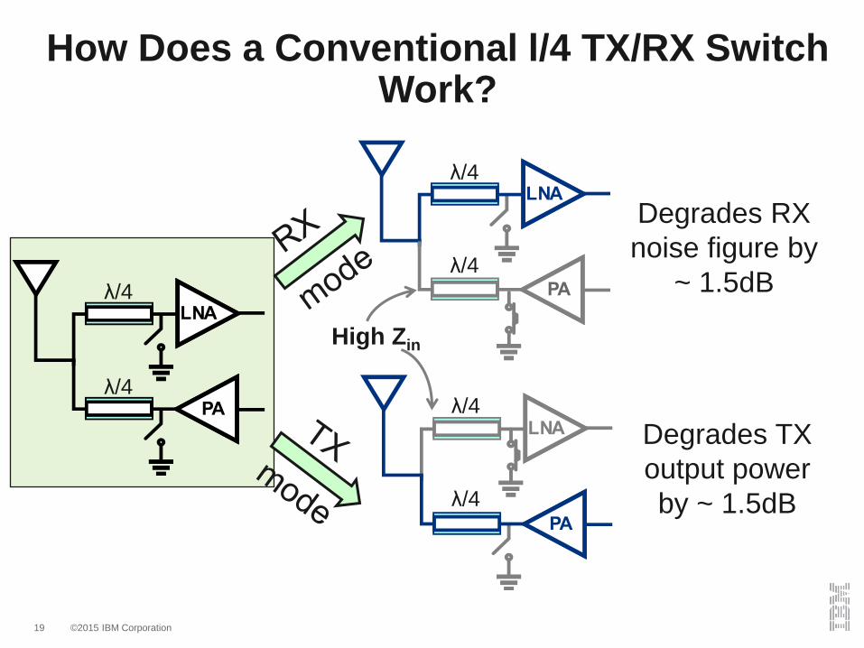
How Does a Conventional l/4 TX/RX Switch Work?
Degrades
RX noise
figure by ~
1.5dBHigh Zin
λ/4
λ/4
λ/4
λ/4Low Zin
©2015 IBM Corporation19
How Does a Conventional l/4 TX/RX Switch Work?
Degrades RX
noise figure by
~ 1.5dB
λ/4
λ/4
λ/4
λ/4
Degrades TX
output power
by ~ 1.5dB
λ/4
λ/4
High Zin

©2015 IBM Corporation20
Proposed Technique Cuts TX Losses
Degrades RX
noise figure by
~ 2dB
λ/4
λ/4
High Zin

©2015 IBM Corporation21
Proposed Technique Cuts TX Losses
Degrades RX
noise figure by
~ 2dB
Does not
degrade TX
output power
λ/4
λ/4
λ/4

©2015 IBM Corporation22
TX/RX Switch Circuit Details

©2015 IBM Corporation23
TX/RX Switch Measurements
TX FE Op1dB improves 1.2dB
LNA NF degrades only 0.6dB
• 1.2dB translates to 23% power savings in the phased
array IC in TX mode

©2015 IBM Corporation24
Key 5G mmWave Challenges…… to IC Design Challenges
Maximize TX output power, with TX/RX integration
Orthogonal phase and gain control
Fine phase resolution
Support for two polarizations
Key IC challenges

©2015 IBM Corporation25
ront end
1
2
Orthogonal Gain & Phase Control
• Transmit/receive frontend‐ Phase invariant gain control
‐ Loss invariant phase shift
Start
Set gain
Set phase
Stop
Gain control Phase controlIdeal

©2015 IBM Corporation26
Phase Invariant Gain Control
Gain
control
Used for
phase
invariance
< ±2
𝑅𝑒0 =𝑐𝜋
𝑔𝑚𝑐𝑗𝑒=
𝜏𝑏𝑐𝑗𝑒
8dB
B. Sadhu, J. Bulzzachelli, and A. Valdes- arcia, “ 28 Hz SiGe BiCMOS phase invariant ”, IEEE
Radio Frequency Integrated Circuits Symposium, pp. 319-322, May 2016.

©2015 IBM Corporation27
Phase Control Using Tunable Transmission Line Phase Shifter
Low Delay = 𝐿1𝐶1
High Delay = 𝐿2𝐶2
L SC L
L
L
SC L
𝐿1𝐶1
=𝐿2𝐶2
= 𝑍𝑜Constant characteristic impedance:
Small L, small C
Large L, large C
Y. Tousi and A. Valdes- arcia, “ Ka-band Digitally-Controlled Phase Shifter with sub-degree
hase recision”, IEEE Radio Frequency Integrated Circuits Symposium, pp. 356-359, May 2016.

©2015 IBM Corporation28
Connecting T-Line Unit Cells in Phase Shifter
L
L
SC L
1 2 4 5 40Unit cells
• Small phase steps
• Large phase range
• Fast switching
• Uniform steps

©2015 IBM Corporation29
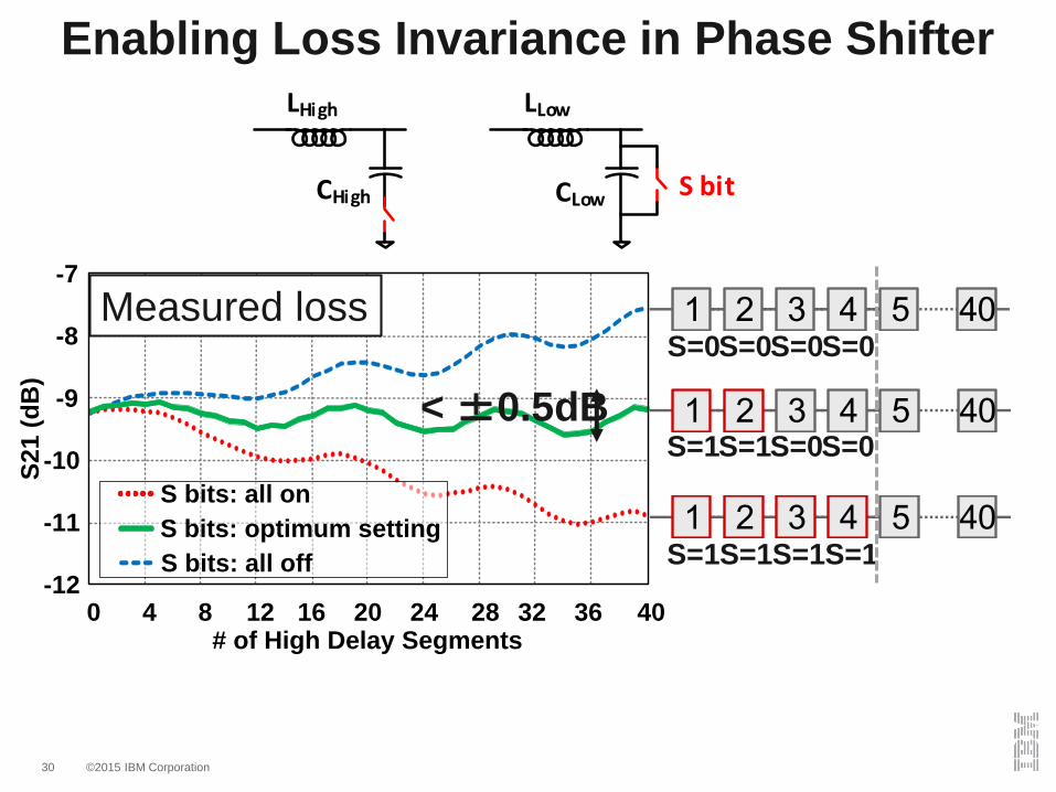
Enabling Loss Invariance in Phase Shifter
1 2 4 5 40
-12
-11
-10
-9
-8
-7
0 4 8 12 16 20 24 28 32 36 40
S2
1 (
dB
)
# of High Delay Segments
Measured loss
©2015 IBM Corporation30
-12
-11
-10
-9
-8
-7
0 4 8 12 16 20 24 28 32 36 40
S2
1 (
dB
)
S bits: all on
S bits: optimum setting
S bits: all off
# of High Delay Segments
Enabling Loss Invariance in Phase Shifter
CHigh
LHigh
CLow
LLow
S bit
S=0
< ±0.5dB
1 2 4 5 40
1 2 4 5 40
1 2 4 5 40
S=0S=0S=0
S=1S=1S=0S=0
S=1S=1S=1S=1
Measured loss

©2015 IBM Corporation31
Key 5G mmWave Challenges…… to IC Design Challenges
Maximize TX output power, with TX/RX integration
Orthogonal phase and gain control
Fine phase resolution
Support for two polarizations
Key IC challenges
©2015 IBM Corporation32
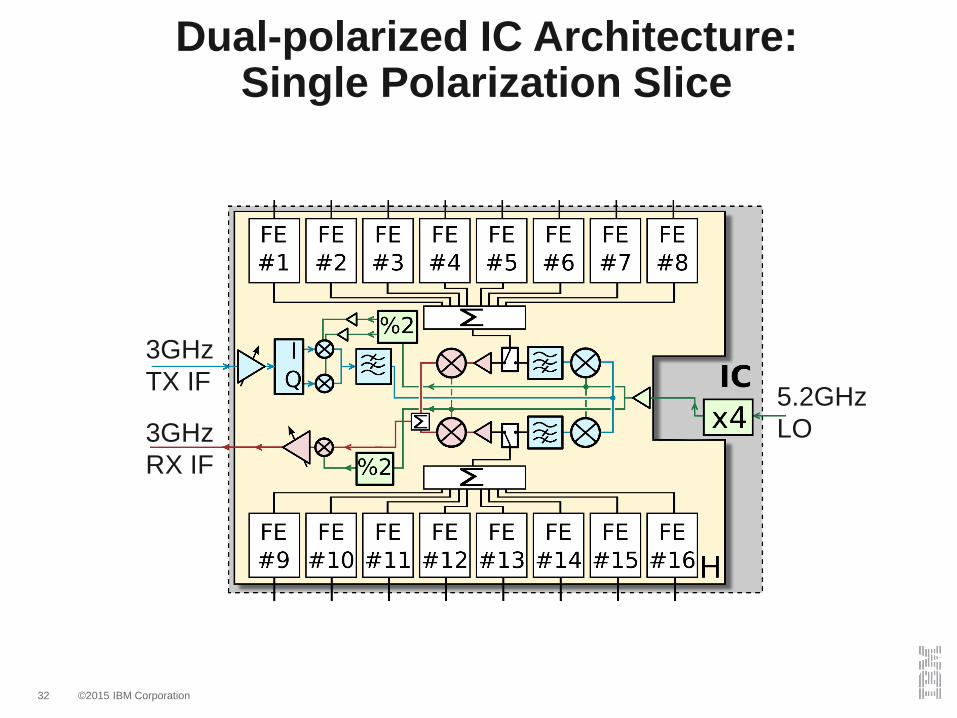
Dual-polarized IC Architecture:Single Polarization Slice
5.2GHz
LO
3GHz
TX IF
3GHz
RX IF

©2015 IBM Corporation33
Dual-polarized IC Architecture:Two Identical 16-Element Slices
5.2GHz
LO
3GHz
H/V TX IF
3GHz
H/V RX IF

©2015 IBM Corporation34
Dual-polarized IC Architecture:32 Elements Feed 16 Dual-Pol Antennas
5.2GHz
LO
3GHz
H/V TX IF
3GHz
H/V RX IF

©2015 IBM Corporation35
Implemented in SiGe 130nm BiCMOS, GF 8HP: fT/fMAX = 200GHz/280GHz
15.8mm
10
.5m
m
Ce
ntra
l D
igita
l
H & V pol TX & RX
IF-RF conversion H & V pol FEs

©2015 IBM Corporation36
Antenna-in-package and phased
array scaling approach

©2015 IBM Corporation37
Fully-Assembled 4-chip Antenna Module
▪ Package dimensions: 70mm x 70mm x 2.7mm
▪ Flip-chip assembly for 4 ICs
• 655 BGA w/ 1.27mm pitch supporting multiple power domains, IF (TX & RX) and LO signals, Digital control and ref clock signals
• Phased array IC and package scalability concept introduced and demonstrated at
94GHz in A. Valdes-Garcia, et al., RFIC 2013 and X. Gu, et al. ECTC 2014
• For 28GHz package details: X. Gu, D. Liu, C. Baks, O. Tageman, B. Sadhu, J.
Hallin, L. Rexberg, and A. Valdes-Garcia, " A Multilayer Organic Package with 64
Dual-Polarized Antennas for 28GHz 5G Communication", IEEE IMS, June 2017.

©2015 IBM Corporation38
Antenna-in-package Array with Air Cavity
▪ Aperture coupled patch antenna
▪ Uniform air cavity between antenna patch and feed structure
▪ 14-layer base substrate based on organic buildup technology

©2015 IBM Corporation39
Measurement Results

©2015 IBM Corporation40
On-wafer Measurement Results
Single TX Path in Full IC:27 Front-Ends Across 9 ICs
©2015 IBM Corporation41
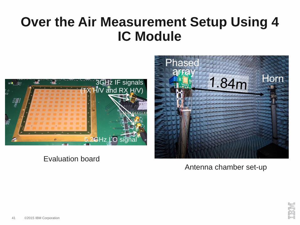
5.2GHz LO signal
3GHz IF signals
(TX H/V and RX H/V)
Over the Air Measurement Setup Using 4 IC Module
Evaluation boardAntenna chamber set-up

©2015 IBM Corporation42
Measured 64 Element Progressive Element Turn On Without Calibration
Measure
d =
35dB
20lo
g(6
4) =
36dB
Measured saturated EIRP in one polarization = 54dBm

©2015 IBM Corporation43
Measured Loss Invariant Phase Control in Phased Array
Gain variation per front-
end < ±0.7dB across
360 phase control

©2015 IBM Corporation44
Measurements of 16 Element Beams from 1 IC
2 simultaneous
beams in RX mode2 simultaneous
beams in TX mode
Results obtained without requiring array calibration
Measured radiation patterns
Ideal radiation patterns calculated with the same angular
resolution available in the measurement setup

©2015 IBM Corporation45
Beam steering + gain control
Measured Beam Steering Control
Beam steering Gain control
Pointing error
Results obtained without requiring array calibration

©2015 IBM Corporation46
Beam steering + gain control
Gain controlBeam steering
Pointing error
Results obtained without requiring array calibration
Measured Beam Steering Control

©2015 IBM Corporation47
Beam steering
Pointing error
Beam steering + gain control
Gain control
Measured Beam Power Control
Results obtained without requiring array calibration

©2015 IBM Corporation48
Beam-Forming Options in TX/RX
Total TRX elements per module (4 ICs) = 128
8 16-element beams 2 64-element beams

©2015 IBM Corporation49
Measurements of Reconfigurable Beams from a Module (4 ICs)
IC 1-4
RX H/RX V
IC1
-VIC
1-H
IC2
-V
IC2
-H
IC3
-H
IC3
-V
IC4
-HIC
4-V
TX H/TX V
8 16-element beams 2 64-element beams
Results obtained without requiring array calibration
©2015 IBM Corporation50
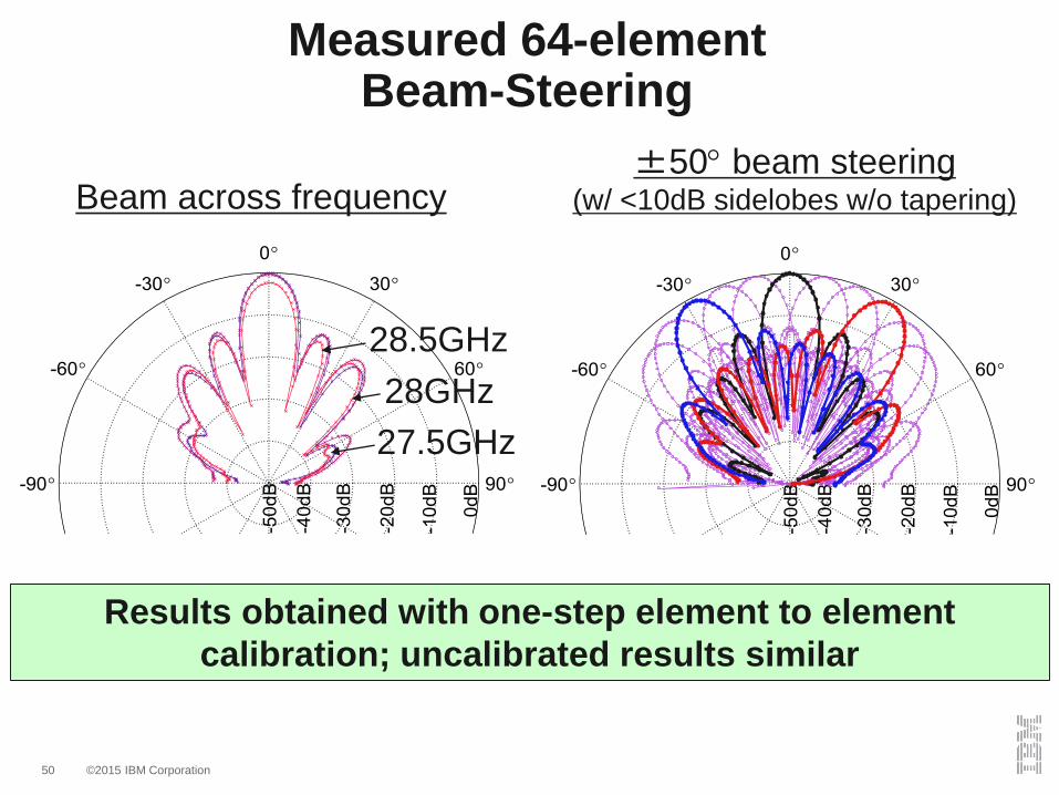
27.5GHz
28GHz
28.5GHz
16-
element
test
setup
Measured 64-element Beam-Steering
Results obtained with one-step element to element
calibration; uncalibrated results similar
Beam across frequency±50 beam steering
(w/ <10dB sidelobes w/o tapering)

©2015 IBM Corporation51
Tapering Measurement Results
Measurement is performed in RX mode with 64
elements in H pol
Tapering uses VGA control and Taylor window

©2015 IBM Corporation52
Measured Beam Switching Speed
Beam switching speed is <4ns
4ns 4ns
Outp
ut
sig
nal envelo
p (
V)
Outp
ut
sig
nal envelo
p (
V)

©2015 IBM Corporation53
Measured TXRX Switching Speed
TXRX switching speed is <100ns
90ns 100ns

©2015 IBM Corporation54
Performance Summary and Comparison for Published 28GHz Si-based Packaged Phased-Array TRX

©2015 IBM Corporation55
Summary and Conclusions
• First reported mmWave 5G base-station IC in a
multi-IC antenna-in-package module (ISSCC 2017)
• Proposed TRX switch improves EIRP without
sacrificing power consumption
• Orthogonal phase and amplitude control for
efficient beam control
• High resolution beam steering with low side-
lobes based on fine phase shift resolution

©2015 IBM Corporation56
Acknowledgments
B. Sadhu1, Y. Tousi1, J. Hallin2, S. Sahl3, S. Reynolds1,
Ö. Renström3, K. Sjögren2, O. Haapalahti3, N. Mazor4,
B. Bokinge3, G. Weibull2, H. Bengtsson3, A. Carlinger3,
E. Westesson5, J.-E. Thillberg3, L. Rexberg3, M. Yeck1,
X. Gu1, D, Friedman1, C. Baks1, D. Liu1, Y. Kwark1, M.
Wahlen3, A. Ladjemi3, A. Malmcrona3.
1IBM T. J. Watson Research Center, Yorktown Heights, NY2Ericsson, Lindholmen, Sweden3Ericsson, Kista, Sweden4IBM Research, Haifa, Israel5Ericsson, Lund, Sweden

©2015 IBM Corporation57
‘Ultimately though, we should expect mmWave systems to become as
inexpensive and ubiquitous as 2.4- and 5-GHz WLAN systems are today. Some
of the early companies developing products in the mmWave space will succeed
and become profitable, and some will fail. But the end result will be
“millimeter-waves for the masses.”’ - Advanced Millimeter Wave
Technologies: Antenna, Packaging and Circuits, Wiley Press, 2009

©2015 IBM Corporation58
References
1. B. Sadhu, Y. Tousi1, J. Hallin, S. Sahl, S. Reynolds, O. Renstrom, K. Sjorgren,
O.Haapalahti, N. Mazor, B. Bokinge, G. Weibull, H. Bengttson, A. Carlinger, E.
Westesson5, J.-E. Thillberg, L. Rexberg, X. Gu, Daniel Friedman, and A. Valdes-
Garcia, "A 28GHz 32-Element Phased-Array Transceiver IC with Concurrent Dual
Polarized Beams and 1.4 Degree Beam-Steering Resolution for 5G
Communication", IEEE International Solid-State Circuits Conference, 2017.
2. X. Gu, D. Liu, C. Baks, O. Tageman, B. Sadhu, J. Hallin, L. Rexberg, and A.
Valdes-Garcia, " A Multilayer Organic Package with 64 Dual-Polarized Antennas for
28GHz 5G Communication", IEEE International Microwave Symposium, June
2017.
3. Y. Tousi and A. Valdes-Garcia, “A Ka-band Digitally-Controlled Phase Shifter with
sub-degree Phase Precision”, IEEE Radio requency Integrated Circuits
Symposium, pp. 356-359, May 2016.
4. B. Sadhu, J. Bulzzachelli, and A. Valdes-Garcia, “A 28GHz SiGe BiCMOS phase
invariant VGA”, IEEE Radio requency Integrated Circuits ymposium, pp. 19-
322, May 2016.

©2015 IBM Corporation59
To earn More…
► IBM Presentation at IEEE 5G Summit November 2015.
“Enabling 5G: mmWave Silicon Integration and Packaging”
► Slides: http://www.5gsummit.org/docs/slides/Bodhisatwa-Sadhu-5GSummit-Toronto-11142015.pdf
► Video:
https://ieeetv.ieee.org/ieeetv-specials/toronto-5g-summit-2015-bodhisatwa-sadhu-enabling-5g-mmwave-silicon-
integration-and-packaging?
► IBM presentation at IEEE 5G Summit November 2016
“mmWave radio design for mobile handsets”
► Video:
https://ieeetv.ieee.org/conference-highlights/seattle-5g-mmwave-radio-design-for-mobile-handsets?
► IBM-Ericsson announcement on phased array for 5G:
http://www-03.ibm.com/press/us/en/pressrelease/51542.wss