Phase Unwrapping Method Based on Heterodyne …...Phase unwrapping method based on heterodyne three...
12
Phase Unwrapping Method Based on Heterodyne Three Frequency Non-equal Step Phase Shift Lei Geng, Yang Liu, Zhitao Xiao ( ✉ ) , Jun Wu, Yang Zhang, Fei Yuan, Zhenjie Yang, Peng Gan, Jingjing Su, and Kun Ye School of Electronics and Information Engineering, Tianjin Polytechnic University, Tianjin, China [email protected] Abstract. This paper presents a phase unwrapping method of heterodyne three frequency non-equal step phase shift, to surmount disadvantages of needing dozens of images in 3-D measurement techniques of multi-frequency phase shift. The method selects three frequencies. Firstly, four-step phase-shifting algorithm is used to calculate wrapped phase and average intensity of the intermediate frequency. Then the wrapped phases of other frequencies are obtained utilizing two-step phase-shifting algorithm. Finally, the absolute phase is calculated using heterodyne method. In addition, the contour sine/cosine filter method is utilized to filter noise by the fringe orientation information. The 3-D points cloud of standard planar and calibration target are reconstructed experimentally. Then the planeness of standard planar is calculated. The centers of markers of calibration target are extracted to calculate distance between two adjacent circles. Experi‐ ments demonstrate that the proposed method reduces the number of fringe images, eliminates the effects of noise efficaciously. Keywords: Non-equal step phase shift · Multi-frequency heterodyne · Phase unwrapping · Contour sine/cosine filter 1 Introduction Grating Projection 3-D measurement technology is an accurate measurement method of three-dimensional profile using phase information. Phase shift method and Fourier transforming profilometry are the main methods to get phases at present. Phase shift method is widely used because of its high precision, resolution and less sensitivity to the surface reflectivity variations [1]. The method calculates wrapped phase values which include surface deformation information by collecting multiple phase-shift fringe patterns. Since the wrapped phase value is in the range of , in order to acquire continuous phase map, the wrapped phase needs to be unwrapped to get the absolute phase value [2]. Phase unwrapping methods can be divided into single-frequency-based and multiple-frequency-based method. Single-frequency-based method obtains only a set of wrapped phase values when measuring, so there are some deficiencies at unwrap‐ ping range, precision and error tolerance. While multiple-frequency-based method gets multiple sets of wrapped phase values, thus it increases the unwrapping range, precision © Springer International Publishing Switzerland 2015 Y.-J. Zhang (Ed.): ICIG 2015, Part III, LNCS 9219, pp. 68–79, 2015. DOI: 10.1007/978-3-319-21969-1_7
Transcript of Phase Unwrapping Method Based on Heterodyne …...Phase unwrapping method based on heterodyne three...

Phase Unwrapping Method Based on Heterodyne ThreeFrequency Non-equal Step Phase Shift
Lei Geng, Yang Liu, Zhitao Xiao(✉), Jun Wu, Yang Zhang, Fei Yuan, Zhenjie Yang,Peng Gan, Jingjing Su, and Kun Ye
School of Electronics and Information Engineering, Tianjin Polytechnic University,Tianjin, China
Abstract. This paper presents a phase unwrapping method of heterodyne threefrequency non-equal step phase shift, to surmount disadvantages of needingdozens of images in 3-D measurement techniques of multi-frequency phase shift.The method selects three frequencies. Firstly, four-step phase-shifting algorithmis used to calculate wrapped phase and average intensity of the intermediatefrequency. Then the wrapped phases of other frequencies are obtained utilizingtwo-step phase-shifting algorithm. Finally, the absolute phase is calculated usingheterodyne method. In addition, the contour sine/cosine filter method is utilizedto filter noise by the fringe orientation information. The 3-D points cloud ofstandard planar and calibration target are reconstructed experimentally. Then theplaneness of standard planar is calculated. The centers of markers of calibrationtarget are extracted to calculate distance between two adjacent circles. Experi‐ments demonstrate that the proposed method reduces the number of fringe images,eliminates the effects of noise efficaciously.
Keywords: Non-equal step phase shift · Multi-frequency heterodyne · Phaseunwrapping · Contour sine/cosine filter
1 Introduction
Grating Projection 3-D measurement technology is an accurate measurement method ofthree-dimensional profile using phase information. Phase shift method and Fouriertransforming profilometry are the main methods to get phases at present. Phase shiftmethod is widely used because of its high precision, resolution and less sensitivity tothe surface reflectivity variations [1]. The method calculates wrapped phase valueswhich include surface deformation information by collecting multiple phase-shift fringepatterns. Since the wrapped phase value is in the range of , in order to acquirecontinuous phase map, the wrapped phase needs to be unwrapped to get the absolutephase value [2]. Phase unwrapping methods can be divided into single-frequency-basedand multiple-frequency-based method. Single-frequency-based method obtains only aset of wrapped phase values when measuring, so there are some deficiencies at unwrap‐ping range, precision and error tolerance. While multiple-frequency-based method getsmultiple sets of wrapped phase values, thus it increases the unwrapping range, precision
© Springer International Publishing Switzerland 2015Y.-J. Zhang (Ed.): ICIG 2015, Part III, LNCS 9219, pp. 68–79, 2015.DOI: 10.1007/978-3-319-21969-1_7

and reduces the error influence. Unwrapping method based on multi-frequency mainlyincludes Gray codes and multiple frequency phase shift method [3, 4]. Gray code methodis more sensitive to light intensity and the surface shade of measured objects, which maylead to incorrect decoding of pixel boundaries, susceptible to noise, and also, the meas‐urement range is restricted to the number of Gray code fringes. Multi-frequency phase-shift method improves the measurement accuracy and measurement range by addingfringes of different frequencies, thus its adaptability is enhanced. Currently, accuracyimprovement by increasing the number of frequencies is an important tendency of multi-frequency phase shift method [5]. However, this method requires multiple images takenat different frequencies.
Generally speaking, the grayscale of encoding fringe pattern is cosine distributionin the Grating Projection 3-D measurement technology. However, amount of noise willbe caused by the nonlinear output of projection system, electric noise and environmentalnoise. Errors would be produced in the phase recovery, which can influence the three-dimensional reconstruction of discontinuous object’s surface. So phase error should bereduced by additional method. Firstly, nonlinear correction is used to reduce the phaseerror in the projection system, but it requires plenty of time and the gamma value ofprojector should be relatively fixed [6]. Secondly, the phase error should be compen‐sated. Several methods are proposed [7–9]. However, the computation of spline fittingmethod [7] is rather complex. Look-up-table method [8] needs plenty of time and rela‐tively stable environment. Image filter method [9] based on frequency domain or spacedomain can eliminate noise and reduce the phase error greatly, but the jump informationof object boundary will be lost when the surface contains different height.
Our main contribution is that a method of heterodyne three frequency non-equalstep phase shift combined with filter is proposed. Firstly, three frequency cosine wavesare selected, and each cosine wave is shifted with different steps. Only by projectingeight fringe patterns, the phase map with rather high quality can be obtained. Secondly,the projection system is optimized by nonlinear correction. Thirdly, before the phasemaps are unwrapped, the contour cosine filter method proposed by Fu [10] is used toreduce the noise caused by difference frequency superposition. The advantages of thismethod are that, accurate measurements can be realized by fewer projection pictures,inconsistent points on wrapped phase maps are filtered effectively by fringe orientationinformation.
2 Phase Unwrapping Theory of Three Frequency Non-equal StepPhase Shift
In this paper, eight fringe patterns of three different frequencies are projected (inter‐mediate frequency is four step phase-shift fringes, frequency and is two stepphase-shift fringes). Firstly, phase unwrapping theory of non-equal step phase shift isused to calculate light intensity of background and wrapped phase value offrequency . The wrapped phase value and of and are obtainedin the case that the background intensity is known. Then three wrapped phases shouldbe carried on contour sine/cosine filter separately. According to the heterodyne theory,
Phase Unwrapping Method 69

the phase function of equivalent frequency is obtained by superposing thedifference frequency values of and , and the phase function of equivalent frequency is obtained by and . Then the phase func‐tions should be performed sine/cosine filter respectively. The phase function containing deformation information of object surface is calculated by double hetero‐dyne. Finally, the point cloud data of object surface will be obtained by phase matchingmethod based on binocular stereo vision. The flow chart is shown as Fig. 1.
Start
Project and collect eight fringe images
Calculate the strength of the ambient light and the wrapped phase for the
wavelenght( )2 x ,yϕΔ
2λ
Calculate the wrapped phase and for the wavelength and
( )1 x ,yϕΔ( )3 x ,yϕΔ
1λ 3λ
Separately filtering for each frequency wrapped phase
Calculate the wrapped phase for the equivalent wavelength with and
( )12 x ,yθ12λ ( )1 x ,yϕΔ
( )2 x ,yϕΔ
Calculate the wrapped phase for the equivalent wavelength with and
( )23 x ,yθ23λ ( )2 x ,yϕΔ
( )3 x ,yϕΔ
Filtering respectively
Calculate the wrapped phase for the equivalent wavelength with and
( )123 x ,yθ123λ ( )12 x ,yθ
( )23 x ,yθ
Phase image matching
3D Reconstruction
End
Fig. 1. The flowchart of the proposed method
2.1 Non-equal Step Phase Shift Method
In grating projection 3-D measurement system, cosine encoding fringes are projectedto the surface of measured object and are modulated to be deformation fringes by objectsurface information. Assuming that the projection light intensity satisfies the standardcosine distribution, the light intensity distribution function of the deformation fringepatterns is:
(1)
Where, indicates the light intensity of deformation fringe patterns; is theintensity of background; is the modulation amplitude; is the frequency offringes; and denotes the phase function to be solved. The formula contains threeunknown quantities. Therefore, it requires at least three light intensity functions to solvephase value of one measured point.
Phase unwrapping method based on heterodyne three frequency non-equal stepphase shift is using different steps phase shift algorithm to calculate wrapped phase
70 L. Geng et al.
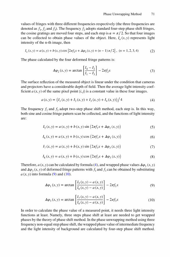
values of fringes with three different frequencies respectively (the three frequencies aredenoted as , and ). The frequency adopts standard four-step phase shift fringes,the cosine gratings are moved four steps, and each step is . So that four imagescan be collected to obtain phase values of the object. Here, represents lightintensity of the n-th image, then
(2)
The phase calculated by the four deformed fringe patterns is:
(3)
The surface reflection of the measured object is linear under the condition that camerasand projectors have a considerable depth of field. Then the average light intensity coef‐ficient of the same pixel point is a constant value in these four images.
(4)
The frequency and adopt two-step phase shift method, each step is. In this way,both sine and cosine fringe pattern scan be collected, and the functions of light intensityare:
(5)
(6)
(7)
(8)
Therefore, can be calculated by formula (4), and wrapped phase values and of deformed fringe patterns with and can be obtained by substituting
into formula (9) and (10).
(9)
(10)
In order to calculate the phase value of a measured point, it needs three light intensityfunctions at least. Namely, three steps phase shift at least are needed to get wrappedphases by the theory of phase shift method. In the phase unwrapping method using threefrequency non-equal step phase shift, the wrapped phase value of intermediate frequencyand the light intensity of background are calculated by four-step phase shift method.
Phase Unwrapping Method 71

Wrapped phase values of the other two frequencies can be obtained by two-step phaseshift when light intensity of background is known. In this way, projection image scanbe reduced. The phase map obtained containing three-dimensional morphologies infor‐mation of object is in the range of . Therefore, the phase is unwrapped by heter‐odyne theory to recover the three-dimensional morphologies of the object.
2.2 Heterodyne Theory for Phase Unwrapping
Heterodyne theory [3] is to obtain a new phase function of frequency bysuperposing the difference frequencies of fringe phase function and withfrequency and . As is shown in Fig. 2, , and are wavelengths correspondingto fringes of different frequencies , and .
Fig. 2. Heterodyne principle
Then, the equivalent wavelength can be expressed as:
(11)
According to heterodyne theory, the continuous phase map in the whole range can beobtained by unwrapping the phase map wrapped within . Assuming that wave‐lengths corresponding to different frequencies are respectively , and , the equiv‐alent wavelength can be obtained by and , is calculated by and , and is gotten by and . In order to obtain the continuous absolute phase map in thewhole range, the equivalent wavelength cannot be smaller than the number of rowspixels of fringe image. That is, .
The unwrapping formula for the phases of fringes with different frequencies is:
(12)
Where, indicates the absolute phase, is series of fringes.The fringe wavelengths of the same point on the surface of measured object are
and ( equals to 1, 2, 12, and equals to 2, 3, 23 respectively). Phase function of can be obtained by the following formula:
72 L. Geng et al.

(13)
(14)
Substituting it into formula (12), the absolute phase of deformed fringe patternswith can be obtained by:
(15)
(16)
(17)
Where, indicates the absolute phase of deformation fringe pattern with frequency which is obtained by and , is the absolute phase of deformation
Fig. 3. Unwrapping algorithm based on three frequency non-equal step phase shift technology
Phase Unwrapping Method 73

fringe pattern with obtained by and . In order to reduce the error, theabsolute phase is the average of and .
Eight vertical fringes meeting coding scheme of three frequency non-equal stepphase shift are generated by computer, whose corresponding wavelengths are ,
and (Unit: pixels/cycle). The process of phase unwrapping is shown asFig. 3.
Phase unwrapping by three-frequency heterodyne is the method based on dual-frequency phase shift [4]. The equivalent wavelength is calculated by and withfrequency and . If wrapped phase of and contains noise, there will be noise of
caused by superposition of difference frequency. As is shown in Fig. 4, there areplenty of noises in wrapped phase due to the system interference, environmental noiseand other factors. Therefore, the wrapped phase maps need filtering.
4
Phas
e/ra
d
Pixel 250200150 10050 0
-2
-4
0
2 Phase error
Noise
12
2
1
λλλ
Fig. 4. Phase error and noise
3 Phase Map Filtering
If the absolute wrapped phase is filtered by traditional method directly, the jump infor‐mation of phase will be lost while removing noises. The periodic jump information ofsine/cosine images will not be damaged due to the gray values of the images are contin‐uous. It is proposed to filter wrapped phase maps by sine/cosine filter in this paper. Sine/cosine maps of phase are calculated firstly. Then, the two resultant maps are conductedmedian filtering in contoured window by fringe orientation information to remove noise.Finally, phase map will be obtained from the filtered sine/cosine images by divisionoperation.
3.1 Gradient Method for Fringe Orientation Images
The minimum difference of pixel along the tangential direction of fringe, and themaximum difference is along the normal direction. Therefore, differences of each pointalong all directions are calculated, and the direction of fringe is corresponding to theminimum value. Gradient method [5] is frequently used to obtain orientation of fringesdefined as:
74 L. Geng et al.

(18)
Where, is the orientation of fringes, is the phase.
3.2 Determination of Fringes Contoured Windows
The purpose of calculating direction of fringes is to determine the contours and normalcurves. Contours are locally parallel to current trend of fringes, and normal curves arepartially perpendicular to current trend of fringes.
Here, is set as the coordinates of a certain point of the image, the directionof fringe at this point is . The fringe orientation image shows that direction value isalong the tangential direction of fringe contour. The fringe contour can be approximatelyreplaced by tangential in the neighborhood of current point. The two adjacent points
and of the current point on contour can be obtainedaccording to the fringe orientation image:
(19)
Similarly, and can be calculated. A curve through and along the direction of fringe can thus be obtained, that is, fringe contour.
Phase value of each point on the curve is equal to the phase value of point ,namely, phase of fringe remains unchanged on the contour.
While the point obtained may not be integer. Fringe orientation value of point should be replaced by the linear interpolation of the four integer pixels adjacent
to . In this way, error caused by fringe orientation images only taking values oninteger pixels will be reduced.
3.3 Sine/Cosine Filter Method
Since phase of wrapped phase map is discontinuous, current pixel point satisfies: where, is the size of image. Sine/cosine
components , are set as , , and they are continuous. Namely, thediscontinuous phase can be represented by its continuous vector . Afterthat, the sine/cosine images are conducted median filtering sequentially in contouredwindow. Finally, can be obtained by and :
(20)
Phase value obtained by formula (20) is in the range of , then quadrantsof , can be determined according to its plus-minus, and its range should be extendedto .
Phase Unwrapping Method 75
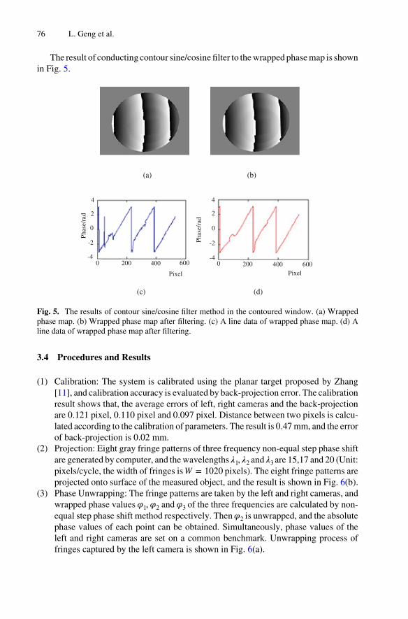
The result of conducting contour sine/cosine filter to the wrapped phase map is shownin Fig. 5.
(a) (b)
(c) (d)
Pixel
Phas
e/ra
d 4
2
0
-2
-4 0 200 400 600
Pixel
4
2
0
-2
-4 200 0 400 600
Phas
e/ra
d
Fig. 5. The results of contour sine/cosine filter method in the contoured window. (a) Wrappedphase map. (b) Wrapped phase map after filtering. (c) A line data of wrapped phase map. (d) Aline data of wrapped phase map after filtering.
3.4 Procedures and Results
(1) Calibration: The system is calibrated using the planar target proposed by Zhang[11], and calibration accuracy is evaluated by back-projection error. The calibrationresult shows that, the average errors of left, right cameras and the back-projectionare 0.121 pixel, 0.110 pixel and 0.097 pixel. Distance between two pixels is calcu‐lated according to the calibration of parameters. The result is 0.47 mm, and the errorof back-projection is 0.02 mm.
(2) Projection: Eight gray fringe patterns of three frequency non-equal step phase shiftare generated by computer, and the wavelengths , and are 15,17 and 20 (Unit:pixels/cycle, the width of fringes is pixels). The eight fringe patterns areprojected onto surface of the measured object, and the result is shown in Fig. 6(b).
(3) Phase Unwrapping: The fringe patterns are taken by the left and right cameras, andwrapped phase values , and of the three frequencies are calculated by non-equal step phase shift method respectively. Then is unwrapped, and the absolutephase values of each point can be obtained. Simultaneously, phase values of theleft and right cameras are set on a common benchmark. Unwrapping process offringes captured by the left camera is shown in Fig. 6(a).
76 L. Geng et al.

(4) Matching: Geometry of binocular stereo vision is converted to standard geometryof binocular stereo by polar correction algorithm. Namely, the matching point onright image of arbitrary point on left image is on the polar with same row. Thenmatching of points on left and right images is realized according to the constraintof phase values.
(5) Point Cloud Reconstruction: After the matching points of left and right phases mapsare obtained, internal and external parameters of the camera are used to restore thethree-dimensional geometry information of objects based on binocular disparitytheory. The result is shown in Fig. 7.
Fig. 7. The 3-D measurement result of the proposed method
A standard plate with size about 400 mm × 400 mm is measured to test the accuracyof the method proposed. Maximum absolute error of the planar is approximately0.113 mm, and the standard deviation is 0.023 mm.
The planar target of 9 rows and 11 columns markers is placed on 10 different posi‐tions, and center distances of adjacent markers are measured. Assuming the horizontaldistance between adjacent markers is , vertical distance is . The total number of
(a) (b)
Fig. 6. Unwrapping process based on three frequency non-equal step phase shift. (a) Unwrappingphase. (b) Fringe patterns of non-equal step phase shift method.
Phase Unwrapping Method 77
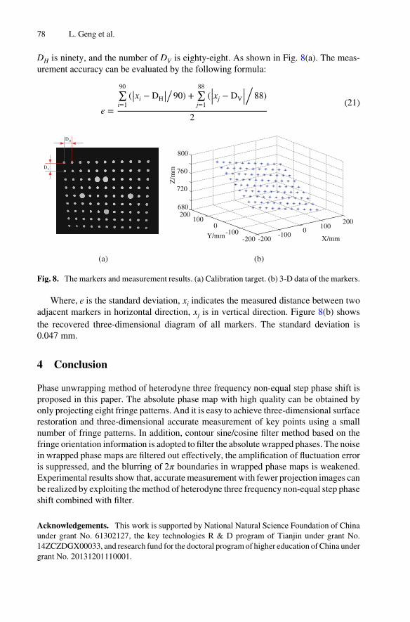
is ninety, and the number of is eighty-eight. As shown in Fig. 8(a). The meas‐urement accuracy can be evaluated by the following formula:
(21)
X/mmY/mm
HD
VD
800
760
720
680200
1000
-100-200 -200
-1000
100200
Z/m
m
(a) (b)
Fig. 8. The markers and measurement results. (a) Calibration target. (b) 3-D data of the markers.
Where, is the standard deviation, indicates the measured distance between twoadjacent markers in horizontal direction, is in vertical direction. Figure 8(b) showsthe recovered three-dimensional diagram of all markers. The standard deviation is0.047 mm.
4 Conclusion
Phase unwrapping method of heterodyne three frequency non-equal step phase shift isproposed in this paper. The absolute phase map with high quality can be obtained byonly projecting eight fringe patterns. And it is easy to achieve three-dimensional surfacerestoration and three-dimensional accurate measurement of key points using a smallnumber of fringe patterns. In addition, contour sine/cosine filter method based on thefringe orientation information is adopted to filter the absolute wrapped phases. The noisein wrapped phase maps are filtered out effectively, the amplification of fluctuation erroris suppressed, and the blurring of boundaries in wrapped phase maps is weakened.Experimental results show that, accurate measurement with fewer projection images canbe realized by exploiting the method of heterodyne three frequency non-equal step phaseshift combined with filter.
Acknowledgements. This work is supported by National Natural Science Foundation of Chinaunder grant No. 61302127, the key technologies R & D program of Tianjin under grant No.14ZCZDGX00033, and research fund for the doctoral program of higher education of China undergrant No. 20131201110001.
78 L. Geng et al.
References
1. Pribanic, T., Obradovic, N., Salvi, J.: Stereo computation combining structured light andpassive stereo matching. Opt. Commun. 285, 1017–1022 (2012)
2. Zhong, K., Li, Z., Shi, Y., et al.: Fast phase measurement profilometry for arbitrary shapeobjects without phase unwrapping. Optics Lasers Eng. 51(11), 1213–1222 (2013)
3. Song, L., Dong, X., Xi, J., Yu, Y., Yang, C.: A new phase unwrapping algorithm based onthree wavelength phase shift profilometry method. Opt. Laser Technol. 45, 319–329 (2013)
4. Ren, W., Su, X., Xiang, L.: 3-D surface shape restoration for breaking surface of dynamicprocess based on two-frequency grating. Opto-Electron. Eng. 37, 144–150 (2010)
5. Cheng, Y.Y., Wyant, J.C.: Multiple-wavelength phase-shifting interferometry. Appl. Optics24, 804–807 (1985)
6. Ayubi, G.A., Di Martino, J.M., Alonso, J.R., et al.: Three-dimensional profiling withbinaryfringes using phase-shifting interferometry algorithms. Appl. Optics 50, 147–154(2011)
7. Xiao, Y., Su, X., Zhang, Q., et al.: 3-D profilometry for the impact process with marked fringestracking. Opto-Electron. Eng. 34, 46–52 (2007)
8. Meneses, J., Gharbi, T., Humbert, P.: Phase-unwrapping algorithm for images with high noisecontent based on a local histogram. Appl. Optics 44, 1207–1215 (2005)
9. Weng, J., Lu, Y.: Integration of robust filters and phase unwrapping algorithms for imagereconstruction of objects containing height discontinuities. Opt. Express 20, 10896–10920(2012)
10. Fu, S., Lin, H., Yu, Q., et al.: Fringe-contoured-window sine/cosine filter for saw-tooth phasemaps of electronic speckle pattern interferometry. Acta Optica Sinica 27, 864–870 (2007)
11. Zheng, Z.: A flexible new technique for camera calibration. IEEE Trans. Pattern Anal. Mach.Intell. 22, 1330–1334 (2000)
Phase Unwrapping Method 79