
Phase Control of HF Chemical Lasers for Coherent … · ... high precision laser ... phase-control...
56
jfV.QP AEROSPACE REPORT NO. ATR-7818408)- SLL 80 126/A/O b^y copy 51 _J Phase Control of HF Chemical Lasers for Coherent Recombination Prepared by C. P. WANG Aerophysics Laboratory The Ivan A. Getting Laboratories and P. L. SMITH Control Analysis Department Guidance and Control Division 16 October 1978 Prepared for VICE PRESIDENT AND GENERAL MANAGER THE IVAN A. GETTING LABORATORIES 19980309 291 DISTRIBUTION STATEMENT A Approved for public release; Distribution Unlimited The Ivan A. Getting Laboratories THE AEROSPACE CORPORATION PlfASEREWRMfc BMD TECHNICAL INFORMATION CENTER WASHINGTON Bt 203OMMÖ
Transcript of Phase Control of HF Chemical Lasers for Coherent … · ... high precision laser ... phase-control...

jfV.QP
AEROSPACE REPORT NO. ATR-7818408)-
SLL 80 126/A/O b^y copy 51
_J
Phase Control of HF Chemical Lasers for Coherent Recombination
Prepared by C. P. WANG Aerophysics Laboratory
The Ivan A. Getting Laboratories and
P. L. SMITH Control Analysis Department Guidance and Control Division
16 October 1978
Prepared for
VICE PRESIDENT AND GENERAL MANAGER THE IVAN A. GETTING LABORATORIES
19980309 291 DISTRIBUTION STATEMENT A
Approved for public release; Distribution Unlimited
The Ivan A. Getting Laboratories
THE AEROSPACE CORPORATION PlfASEREWRMfc
BMD TECHNICAL INFORMATION CENTER
WASHINGTON Bt 203OMMÖ

THE IVAN A. GETTING LABORATORIES
The Laboratory Operations of The Aerospace Corporation is conducting
experimental and theoretical investigations necessary for the evaluation and *
application of scientific advances to new military concepts and systems. Ver-
satility and flexibility have been developed to a high degree by the laboratory
personnel in dealing with the many problems encountered in the nation's rapidly
developing space and missile systems. Expertise in the latest scientific devel-
opments is vital to the accomplishment of tasks related to these problems. The
laboratories that contribute to this research are:
Aerophysics Laboratory: Launch and reentry aerodynamics, heat trans- fer, reentry physics, chemical kinetics, structural mechanics, flight dynamics, atmospheric pollution, and high-power gas lasers.
Chemistry and Physics Laboratory: Atmospheric reactions and atmos- pheric optics, chemical reactions in polluted atmospheres, chemical reactions of excited species in rocket plumes, chemical thermodynamics, plasma and laser-induced reactions, laser chemistry, propulsion chemistry, space vacuum and radiation effects on materials, lubrication and surface phenomena, photo- sensitive materials and sensors, high precision laser ranging, and the appli- cation of physics and chemistry to problems of law enforcement and biomedicine.
Electronics Research Laboratory: Electromagnetic theory, devices, and propagation phenomena, including plasma electromagnetics; quantum electronics, lasers, and electro-optics; communication sciences, applied electronics, semi- conducting, superconducting, and crystal device physics, optical and acoustical —N imaging; atmospheric pollution; millimeter wave and far-infrared technology.
Materials Sciences Laboratory: Development of new materials; metal matrix composites and new forms of carbon; test and evaluation of graphite and ceramics in reentry; spacecraft materials and electronic components in nuclear weapons environment; application of fracture mechanics to stress cor- rosion and fatigue-induced fractures in structural metals.
Space Sciences Laboratory: Atmospheric and ionospheric physics, radia- tion from the atmosphere, density and composition of the atmosphere, aurorae and airglow; magnetospheric physics, cosmic rays, generation and propagation of plasma waves in the magnetosphere; solar physics, studies of solar magnetic fields; space astronomy, x-ray astronomy; the effects of nuclear explosions, magnetic storms, and solar activity on the earth's atmosphere, ionosphere, and magnetosphere; the effects of optical, electromagnetic, and particulate radia- tions in space on space systems.
THE AEROSPACE CORPORATION El Segundo, California
Accession Number: 4014
Publication Date: Oct 16,1978
Title: Phase Control of HF Chemical Lasers for Coherent Recombination
Personal Author: Wang, C.P.; Smith, P.L.
Corporate Author Or Publisher: Aerospace Corporation, El Segundo, CA 90245 Report Number: ATR- 78(8408)-2
Report Prepared for: Space and Missile Systems Organization, Air Force Systems Command, Los Angeles, CA Report Number Assigned by Contract Monitor: SLL 80 126
Comments on Document: Archive, RRI, DEW
Descriptors, Keywords: Phase Control Hydrogen Fluoride HF Chemical Laser Coherent Recombination Servo System Optics Frequency Drift Piezoelectric Transducer Mirror Expression Vector Covariance
Pages: 00047
Cataloged Date: Dec 07, 1992
Contract Number: F04701-77-C-0078
Document Type: HC
Number of Copies In Library: 000001
Record ID: 25484
Source of Document: DEW
Aerospace Report No. ATR-78(8408)-2
PHASE CONTROL OF HF CHEMICAL LASERS
FOR COHERENT RECOMBINATION
Prepared by
C. P. Wang Aerophysics Laboratory
The Ivan A. Getting Laboratories and
P. L. Smith Control Analysis Department Guidance and Control Division
16 October 1978
The Ivan A. Getting Laboratories THE AEROSPACE CORPORATION
El Segundo, Calif. 90245
N>

Report No. ATR-78(8408)-2
PHASE CONTROL OF HF CHEMICAL LASERS
FOR COHERENT RECOMBINATIONS
Prepared
C. P. Wang &~~ Aerophysics Laboratory ol Division
Approved
fhvjyjL H. Mirels, Head Aerodynamics and Heat Transfer
Department
^^ <2tt^ M. Allman, Director
Control Analysis Department Guidance and Control Division
ßfji/* 'a**/ W. R. Warren, Jr. , Director Aerophysics Laboratory The Ivan A. Getting Laboratories
■111-

ABSTRACT
A servo system for phase-locking two HF chemical lasers, operated
on selected lines, has been designed and simulated. A steady-state phase
error is achieved that is adequate for coherent optical recombination. The
results are based on the measured frequency drift of a small HF chemical
laser and the measured frequency response of a piezoelectric transducer
(PZT) mirror driver. A major innovation is the use of rate feedback with a
laser Doppler sensor to extend the useful frequency response of the PZT
driver. Closed-form expressions for the regulator gains derived by quadra-
tic synthesis and state vector covariance are provided.
-v-
CONTENTS
ABSTRACT v
I. INTRODUCTION *
II. HF CHEMICAL LASERS . . ., 3
IE. PZT DRIVER 7
IV. SERVO DESIGN BY QUADRATIC SYNTHESIS • 9
V. IMPLEMENTATION OF RATE FEEDBACK 17
VI. SERVO-TRACKING-ERROR COVARIANCE ANALYSIS 23
VII. SIMULATION RESULTS 25
VIII. CONCLUSION 33
REFERENCES
APPEND DCES:
35
A. QUADRATIC SYNTHESIS OF FEEDBACK REGULATOR 37
B. STEADY-STATE COVARIANCE OF STATE VECTOR ... 43
-Vll-

s
FIGURES
1. Block Diagram of Phase-Control Loop 2
2. Frequency Drift of Free-Running Chemical Laser 4
3. State Feedback Regulator . 11
4. Feedback Gains Versus Phase-Error Weighting Coefficient 13
5. Phase Regulator in Classical Form 14
6. Physical Elements of Servo System 16
7. PZT Driver with Laser Doppler Sensor and Rate Feedback 18
8. Simulated Step Response of PZT Driver With and Without Rate Feedback 20
9. Linearized RMS Phase Error Versus Phase-Error Weighting Coefficient 24
10. Phase Error 26
11. PZT Displacement 27
12. PZT Displacement Rate 28
13. Laser Frequency Shift 29
14. Frequency Tracking Error 30
-IX-

I. INTRODUCTION
The major optical problems for high-power lasers are efficient
power extraction and handling and control of such laser beams with adequate
beam quality and stability. A technique for coherent optical recombination
of several laser beams may have to be developed to solve these problems.
For the coherent optical recombination of such laser beams as the master
1 2 and slave oscillator array (MASOA) system ' and for such laser-frequency
phase-control systems as the coherent optical adaptive technique (COAT)^
and laser frequency stabilization schemes, " a wide bandwidth phase-
control system is required.
The following critical issues for the phase-control of HF chemical
lasers operating on selected lines were examined: (1) What is the frequency
drift of HF chemical lasers? (2) What is the response of available piezo-
electric transducer (PZT) mirror drivers? (3) Can a servo be designed to
phase-lock HF chemical lasers ?
The frequency drift of a small HF chemical laser ' and the frequency
response of a PZT mirror driver were measured, and models were fitted
to the experimental data.
A phase-control servo was designed by means of the quadratic
8 9 synthesis technique. ' Figure 1 is a simplified block diagram of the
servo. A major innovation is the use of rate feedback with a laser Doppler
sensor used on the mirror face to increase the useful PZT frequency 11 12
response ' and reduce the effects of nonlinearities.
1-

PZT SLAVE OSCILLATOR
\ T-J^ DRIVER 'ins
i k
MASTER OSCILLATOR =£>
AO MODULATOR ^
V SERVO HETERODYNE
■* DETECTOR
Fig. 1. Block Diagram of Phase-Control Loop

II. HF CHEMICAL LASERS
7 13 The cw HF(DF) chemical laser ' is a potential high-efficiency,
high-power gas laser, but its gain medium is complicated by the nature of
the chemical reaction and the rotation-vibration transitions, medium nonuni-
14, 15 formity, and mixed inhomogeneous and homogeneous behavior. ' The
frequency stability of a free-running cw HF chemical laser is rather poor, c
on the order of 30 MHz. It is necessary to determine the frequency drift
of the laser to estimate the performance of the servo loop.
Experiments were carried out with a cw HF chemical laser operating
5 7 on a single line. The laser used is described in an earlier paper. ' Briefly,
F atoms are generated by a discharge in a gas mixture of He, O-, and SF, .
The latter is mixed with H?, which is injected just upstream of a transverse
optical cavity. The cavity pressure could vary from 5 to 15 Torr. Typical
single-line output at 2. 87 fxm is 0. 5 W. The gain medium is 10 cm long,
and there is a small signal gain of about 0. 05 cm
A stable resonator was used that had a 2-m radius-of-curvature total
reflector (reflectivity > 95%) and a flat grating (reflectivity 80%) as the
1 output coupling. The resonator and coupling were separated by a distance
) of 150 cm; hence, the empty cavity mode spacing was 100 MHz. A TEM -
mode output beam was obtained by means of a variable aperture inside the
resonator. The totally reflecting mirror was mounted on a PZT driver,
which could move the mirror and scan the laser frequency across the gain

1.0
IVI
0.1
CO
>
ZD
LU QC
cc l_U oo
0.01
0.001
^7
WANG (measured)
MUNCH (Ref.4)
WANG (extrapolated)
r UNIT ► 7i* d 1 PSD
WHITE NOI
TS+1
SE
^ rs+1
Ar± 1
T= 4.5 x 10 /isec 0= 200 rad/yxsec
10' 3 4
10J 10^ FREQUENCY, Hz
10v
Fig. 2. Frequency Drift of Free-Running Chemical Laser
[
-4-

linewidth. An InAs fast detector and a Hewlett-Packard spectrum analyzer
with a plug-in 8553B unit were used to analyze the beat-frequency spectrum.
A 25-cm Fabry-Perot confocal interferometer also was used to measure
the frequency drift spectrum of the laser (Fig. 2). Frequency drift above
1000 Hz is obtained by extrapolating the measured data. The measured
frequency drift was close to but somewhat lower than that measured in Ref. 4.
The difference may be the result of our optics being mounted on a vibration-
isolated optical table (Newport Research Corporation).
The frequency drift is modeled by a second-order Gaussian Markov
random process with cascaded lag filter time constants T and steady-state 5
fluctuation root-mean-square (RMS) CJ. Values of T = 4. 5 x 10 p.sec and
cr = 200 rad/fJLsec fit the measured and extrapolated frequency drift shown in
Fig. 2 very well.

III. PZT DRIVER
The frequency of the lowest order resonance mode for a thin disk-
shaped piezoelectric transducer (PZT) driving a mirror of mass mr which
is much larger than the mass of the PZT driver, is approximately
* = [E= igbt (i) n N m \l 4hm
where k, D, h, and Y are the equivalent spring constant, diameter, thickness,
and Young's modulus of the PZT driver, respectively. Higher order modes
may involve the moment of inertia of the PZT driver. The displacement
Ah of the PZT driver is
Ah = d33Eh (2)
where d_- is the piezoelectric constant, and E is the applied electric field
strength. For high-frequency response, h and m should be as small as
possible. The thickness is limited by the required maximum displacement
and the maximum electric breakdown voltage or maximum electric-field
strength.
The mechanical response of the PZT and mirror is modeled by a
second-order transfer function
2 (JU
H(s)=-5 5- <3> s + 2£u> s + CJU
' n n
where uu is the resonance frequency, and t, is the damping coefficient. For a
typical PZT mirror driver, well within the state of the art,
-7-

CO = 0. 03 rad/fisec (5 kHz) and £, =0.6. Because of excessive PZT phase
lag, the frequency response of a simple single-loop positioning servo is
limited to about 3 kHz — not high enough to follow the laser frequency vari-
ations and maintain phase lock. A more sophisticated servo design is
required.
•
-8-

IV. SERVO DESIGN BY QUADRATIC SYNTHESIS
Servo design for linear, multivariable systems is well developed.
Linearization of nonlinear systems makes linear design methods widely appli-
cable, particularly to laser phase control.
In the results reported here the uncertainty in models and signals is
ignored, and a range of gains is investigated to determine the relationships
of the PZT bandwidth, laser drift, and the phase error. Additional analysis
is required to specify the necessary signal-to-noise ratios of the loop ele-
ments to ensure that the performance of the idealized, deterministic design
can be achieved.
The quadratic synthesis method was used to design the phase-control
system. The quadratic synthesis approach is preferred to other linear
synthesis techniques such as the frequency-domain and root-locus methods,
8.9 pole-placement, and compensator parameter optimization ' because the com-
plexities of more detailed models and multiple PZT drivers can be analyzed
in a progressive manner by means of the same basic approach. 12
Quadratic-control-system synthesis always results in a stable system,
although some designs may require unrealistically high gains or result in
actuator excursions outside the allowable dynamic range or valid model
linearization region. Hence experience and caution are required in interpret-
ing the results, and a simulation is used to verify the design.
-9-
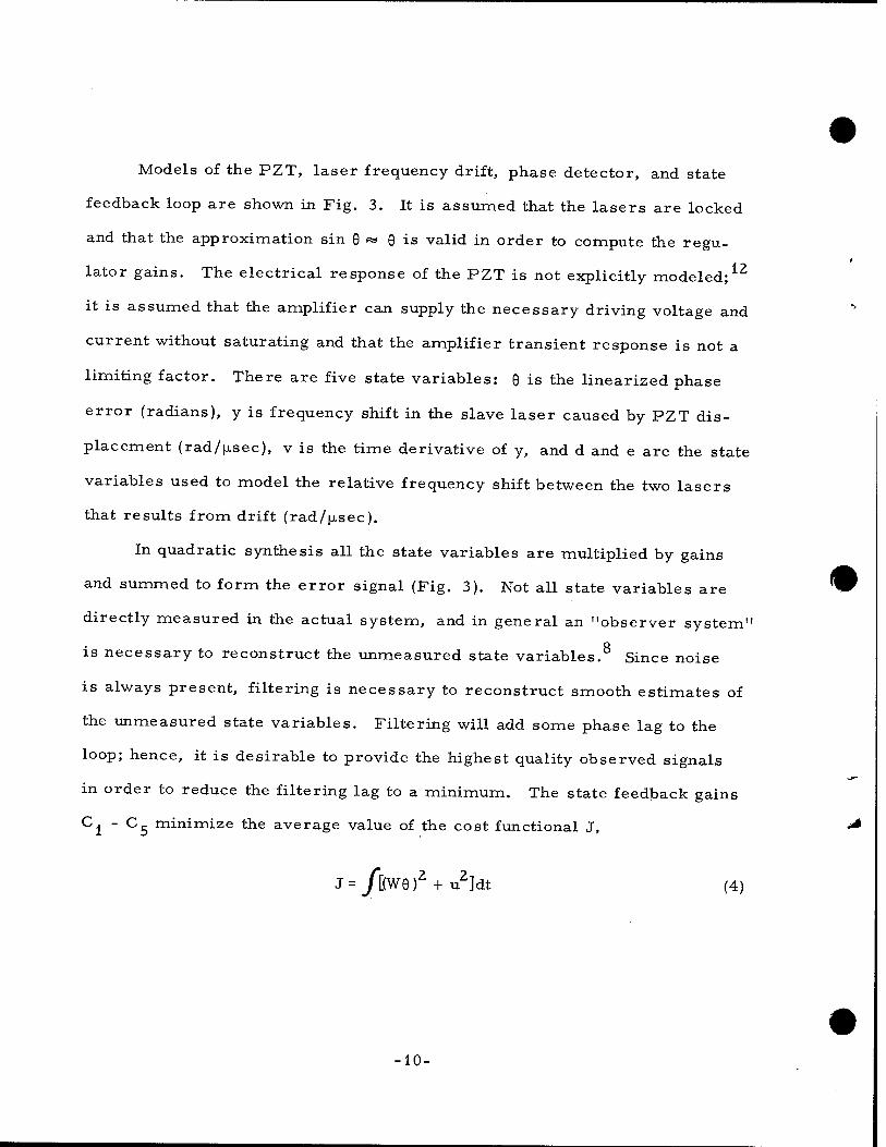
Models of the PZT, laser frequency drift, phase detector, and state
feedback loop are shown in Fig. 3. It is assumed that the lasers are locked
and that the approximation sin 0 «* 0 is valid in order to compute the regu-
lator gains. The electrical response of the PZT is not explicitly modeled;12
it is assumed that the amplifier can supply the necessary driving voltage and
current without saturating and that the amplifier transient response is not a
limiting factor. There are five state variables: 6 is the linearized phase
error (radians), y is frequency shift in the slave laser caused by PZT dis-
placement (rad/^sec), v is the time derivative of y, and d and e are the state
variables used to model the relative frequency shift between the two lasers
that results from drift (rad/jisec).
In quadratic synthesis all the state variables are multiplied by gains
and summed to form the error signal (Fig. 3). Not all state variables are
directly measured in the actual system, and in general an "observer system"
is necessary to reconstruct the unmeasured state variables.8 Since noise
is always present, filtering is necessary to reconstruct smooth estimates of
the unmeasured state variables. Filtering will add some phase lag to the
loop; hence, it is desirable to provide the highest quality observed signals
in order to reduce the filtering lag to a minimum. The state feedback gains
Cl ~ C5 minimize the average value of the cost functional J,
J = /[(W0)2 + u2]dt (4)
10-

LASERS/PZT/PHASE DETECTOR
l-O .PHASE ERROR
Fig. 3. State Feedback Regulator
•11-

•
where u is the PZT commanded frequency shift, and W is the phase error
weighting coefficient. In the quadratic synthesis method W is the parameter
that the designer adjusts to achieve the desired response. Increasing W
increases the gains and decreases the phase error. There are practical
limits on the size of W (and the resultant feedback gains) because of noise,
unmodeled nonlinearities and resonance modes, and power limits. The
major advantage of the quadratic synthesis method, particularly in a pre-
liminary design study such as this, is that the controller design is a function
of only one independent parameter (W).
Preliminary results indicated that the control system could be simplified
without an appreciable loss in performance if it is assumed that C. = C? and
C5 = 0 (Appendix A). With this approximation the state feedback regulator
reduces to the conventional servo-loop architecture for an actuator position-
ing control system (Fig. 4), i.e., an inner rate stabilized loop and an outer
position loop with high-frequency boost compensation. If 6, 6, and v are mea-
sured directly, no observer system is necessary. Rate feedback is mandatory
in conventional precision tracking loops to reduce the phase lag of lightly Q it
damped gimballed masses. ' In this application rate feedback reduces the
PZT phase lag by increasing the damping, which in turn permits a greater
degree of high-frequency boost in the outer position loop. Rate feedback also
reduces the effect of nonlinearities in the PZT response, a result that cannot
be achieved with outer loop phase lead compensation alone. Figure 5 is a
•12-

+
HIGH-FREQUENCY BOOST
WHITE NOISE
+
I
fh TS+1
PZT
—»6 , »Q— +
un
S2+2^nS+ain2
v=y
PHASE DETEC
sinlö)
ION
Fig. 4. Feedback Gains Versus Phase-Error Weighting Coefficient
13-

PHASE ERROR WEIGHTING COEFFICIENT W, /isec
Fig. 5. Phase Regulator in Classical Form
14-

plot of the loop gains as a function of W. The gains are computed by the
routine procedure of solving the steady-state Ricatti equation associated
8 9 with the state equations and the cost functional J. '
Figure 6 is a block diagram of the physical elements of the phase
control servo.
-15-

□- 7T LASER 1 e 1 1
\ OUTPUT rc\ ^ '
J rl • ■ TZ
LASER DOPPLER SENSOR
PZT LASER 2 AO
MODULATOR ' \
' ' • i t 1
CONTROL AND
AMPLIFIER
DC BIAS
PHOTO- DETECTOR
iu'r + ilai -w lr
C3 ■ ' -filf,-^! HIGH-
VOLTAGE AMPLIFIER
OSCILLATOR U)'
PHASE DETECTOR
FREQUENCY DISCRIMINATOR
c2 i i
1
' ■ + PZT CONTROL COMPENSATION
AND FILTER
LP FILTER AND
PREAMPLIFIER ^v; C, sin I ^i-^J
+ CM y.,-aiJ
Fig. 6. Physical Elements of Servo System
16-

V. IMPLEMENTATION OF RATE FEEDBACK
A major design problem is to derive the PZT displacement rate signal.
Figure 7 is a schematic diagram of the PZT driver with a laser Doppler
sensor for measuring the displacement rate.
Laser Doppler velocimeters have been extensively used for velocity
measurement. Basically, when light is scattered or reflected from a
moving object, its frequency is shifted as a result of the Doppler effect.
The frequency shift Au> is related to the velocity V by the relation
AUD = V • (k. - k0) = 2 — uu cos 0 cos %■ (5) L) 1 U C -Li Lt
where k*. and k are the wave vectors of the incident light and scattered
light, respectively; c is the speed of light; <p is the angle between V and
(k. - k_); \b is the angle between k. and -k0; and cu is the frequency of the 1 Z 1 Z -Li
light source.
For the configuration shown in Fig. 7, both cos 0 and cos 0/2 are
near 1. For the application here, the mirror velocity is of the order of _5
10 m/sec, which corresponds to a frequency shift Acu of 20 Hz. An
optical heterodyne and acousto-optical modulation technique is proposed to
detect such low frequencies with sufficient bandwidth. As shown in Fig. 7,
the laser beam is split by the first beam splitter. The reflected beam is
reflected again by the mirror and reaches a second beam splitter. The
transmitted beam goes through an acousto-optical modulator, which shifts
17-

CONTROL t>. SIGNAL ~*vy-
—n
HV AMPLIFIER
PZT DRIVER
MIRROR
LOW PASS FILTER
BEAM SPLITTER
FM- DEMODULATOR
PHOTO- DETECTOR
BEAM SPLITTER
OSCILLATOR
HeNe LASER
-ACOUSTO-OPTICAL MODULATOR
Fig. 7. PZT Driver with Laser Doppler Sensor and Rate Feedback
-18-
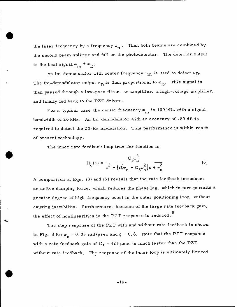
the laser frequency by a frequency u) . Then both beams are combined by
the second beam splitter and fall on the photodetector. The detector output
is the beat signal u) ± a^.
An fm demodulator with center frequency com is used to detect a>j).
The fm-demodulator output v is then proportional to u^. This signal is
then passed through a low-pass filter, an amplifier, a high-voltage amplifier,
and finally fed back to the PZT driver.
For a typical case the center frequency u> is 100 kHz with a signal
bandwidth of 20 kHz. An fm demodulator with an accuracy of -80 dB is
required to detect the 20-Hz modulation. This performance is within reach
of present technology.
The inner rate feedback loop transfer function is
„ 2 C,CD
Hc(s)=:-1E— 5_n (6)
\ n 3 n/ n
A comparison of Eqs. (3) and (6) reveals that the rate feedback introduces
an active damping force, which reduces the phase lag, which in turn permits a
greater degree of high-frequency boost in the outer positioning loop, without
causing instability. Furthermore, because of the large rate feedback gain,
J 8
the effect of nonlinearities in the PZT response is reduced.
The step response of the PZT with and without rate feedback is shown
in Fig. 8 for u) = 0. 03 rad/usec and C = 0.6. Note that the PZT response
with a rate feedback gain of C„ = 421 (isec is much faster than the PZT
without rate feedback. The response of the inner loop is ultimately limited
-19-

w = 0.03 rad//isec
C = 0.6
Cq = 421 /isec
-0.4 J_ 1 1 0 200 400 600 800 1000 1200 1400 1600 1800 2000
TIME, fisec
Fig. 8. Simulated Step Response of PZT Driver With and Without Rate Feedback
-20-

by the rate sensing noise and higher order structural resonances. How far
the PZT response can be extended by the use of rate feedback must be
determined experimentally.
■21-

VI. SERVO-TRACKING-ERROR COVARIANCE ANALYSIS
The RMS steady-state phase error can be computed as a closed-form
function of W and the RMS random frequency drift a if the approxima-
tion sin 6 «* 6 is valid. The procedure is described in Ref. 8 and the results
are given in Appendix B. Figure 9 is a plot of the RMS phase error versus
W for UJ = 0. 03 rad/fxsec (5 kHz), a = 4l X 200 |j.sec = 282 |j.secfor two lasers),
T = 4. 5 x 10⁵ |jLsec, and £ =0.6. The lower region of the plot (below the
dashed line) is valid for the linearized models; above about 0. 1 rad the linear-
izing assumption of sin 9^0 may introduce larger error.
For the frequency-drift and PZT parameters considered, i.e., a noise-free
3 -1 control system with feedback gains corresponding to W = 10 [xsec , the plot
(Fig. 9) indicates that the RMS phase error is about 12 deg.
A single PZT servo may require excessively large excursions. The
typical approach is to use a high-gain, low-frequency servo to reduce the
large-excursion frequency drift in conjunction with a low-gain, high-frequency
servo to remove the residual high-frequency, small-excursion drift. The
low-frequency servo presents no design problems; the concern here is with
canceling the high-frequency (above 1000 Hz) drift. If it is assumed, for
example, that the low-frequency servo reduces the frequency variations below
100 Hz and the residual high-frequency drift is specified by a = 0.45 rad/jasec _ i
and T = 717 fisec, the servo gains corresponding to W = 10 usec are then
adequate to drive the residual phase error to an RMS value of less than
3 deg (Fig. 9).
•23-

PHASE ERROR WEIGHTING COEFFICIENT W, /zsec
Fig. 9. Linearized RMS Phase Error Versus Phase-Error Weighting Coefficient
-24-

VII. SIMULATION RESULTS
The phase-control system in Fig. 4 was simulated on a CDC 7600
computer. Gaussian distributed random numbers were used to simulate
the white noise input to the frequency-drift shaping filters. A total of 20
differential equations (5 for the servo and 15 for the linearized covariance
analysis) were numerically integrated by means of a fixed-step Runge Kutta
algorithm with a step size of 0. 5 |isec for a period of 2000 |j.sec.
Figures 10 to 14 are time-history plots of the state variables with
the lasers locked initially (9 = 0) for co = 0. 03, £ = 0. 6, a = 0.45 rad/fxsec,
T = 7.2 X 10 |jLsec, and the gains corresponding to W = 10 p.sec_1.
The corresponding i-c bounds from the state covariance equations
are overlayed on the state variables. Although the covariance analysis is
based on the linearized model, the results are valid (signal lies inside
bound 67% of the time) when sin 8^9, which is true for this case after
lock-up has been achieved. 1 6
The transient response is highly'nonlinear. A typical case with an
initial frequency difference of 10.0 MHz locks in 60 fisec. Cycle slipping
occurs, but phase lock-up is rapidly achieved because of the frequency feed-
back term in the regulator error signal. The actual lock-up time may be
limited by the saturation of the PZT driver amplifier, which was not modeled.
The excellent agreement between the simulation and the linearized
covariance analysis simplifies the performance analysis considerably.
-25-

CD CO CD
C/O
900 1200 TIME,//sec
2100
Fig. 10. Phase Error
•26-

300 600 900 1200 1500 1800 2100 TIME, fi sec
Fig. 11. PZT Displacement
-27-

1.0
0.8
0.6
o CD GO
-a CD
0.4
0.2
-0.2 C-J
£-0.4 GO
-0.6-
-0.1
8-
300 600 900 1200 TIME, /isec
1500 1800 21 00
Fig. 12. PZT Displacement Rate
■28-

300 600 900 1200 1500 1800 2100 TIME, /^sec
Fig. 13. Laser Frequency Shift
■ 29-

0.0025
CJ cu GO
"CJ CD
CC CD cc cc LU
CD 12 ^L C_3 <t CC I— >- CJ
a -0.0015
E -0.002
-0.0025 300 600 900 1200, 1500 1800 2100
TIME, fi sec
Fig. 14. Frequency Tracking Error
-30-

If more refined laser drift measurements require different values of cr or T
or if a different PZT driver requires changes in £, or GO , new control gains
and the steady-state RMS phase error can be rapidly determined. Control-
system parameter optimization is also possible.
-31-
VIII. CONCLUSION
On the bases of the PZT characteristics and the laser frequency drift
model derived from experimental data, adequate phase-control of HF chemi-
cal lasers appears to be feasible if sensor noise and PZT nonlinearities do
not seriously degrade the servo performance. A major improvement over
previous laser phase control designs is the use of PZT displacement rate
feedback to stabilize and extend the frequency response of the servo.
■33-

REFERENCES
1. C. P. Wang, "Master and Slave Oscillator Array System for Very Large Multiline Lasers," Appl. Opt. r7_, 83-86 (1978).
2. C. L. Hages and L. M. Laughman, "Generation of Coherent Optical Pulses, " Appl. Opt. 16, 263-264 (1977).
3. J. W. Hardy, "Active Optics: A New Technology for the Control of Light," Proc. IEEE 66, 651-697 (1978).
4. J. Munch, M. A. Kolpin, and J. Levine, "Frequency Stability and Stabilization of a Chemical Laser, " IEEE J. Quantum Electron. QE-14, 17-22 (1978).
5. C. P. Wang, "Frequency Stability of a CW HF Chemical Laser, " J. Appl. Phys. 47, 221-223 (1976).
6. C. P. Wang and R. L. Varwig, "Frequency Stabilization of HF Lasers by Means of Beat Signals and Anomalous Dispersion, " Presented at the Tri-Service Chemical Laser Symposium, Redstone Arsenal, Alabama, 1-3 March 1977.
7. D. J. Spencer, J. A. Beggs, and H. Mirels, "Small -scale CW HF -DF Chemical Laser, " J. Appl. Phys. 48, 1206-1211 (1977).
8. A. E. BrysonandY. C. Ho, Applied Optimal Control, Blaisdell, Mass. (1968).
9. M. Athans, "The Role and Use of the Stochastic Linear-Quadratic- Gaussian Problem in Control System Design, " IEEE Trans. Automatic Control, AC-16, 529-552 (1971).
10. C. P. Wang, "Laser Anemonetry, " Am. Sei. 65, 289-293 (1977).
11. S. A. Davis, Feedback and Control Systems, Simon and Schuster, New York (1974), Chapter 6. "
12. C. P. Wang and P. L. Smith, High Frequency PZT Driver by Means of Laser Doppler Sensor and Rate Feedback, ATR-79(B40B)-1. The Aerospace Corporation, El Segundo, California (July 1978).
13. W. R. Warren, Jr., "Chemical Lasers, " Aeron. and Astron. _13_, 36-39 (1975).
•35-

14. H. Mirels, "Inhomogeneous Broadening Effects in CW Chemical Lasers, " (Unpublished).
15. C. P. Wang, and R. L. Varwig, "Longitudinal Mode Beat Intensities in a CW HF Chemical Laser, " Appl. Phys. Lett. 29, 345-347 (1976).
-36-

APPENDIX A
QUADRATIC SYNTHESIS OF FEEDBACK REGULATOR
A. OPTIMAL CONTROL EQUATIONS
1. PHYSICAL SYSTEM MODEL
x = Fx + Gu
2. CONTROLLER
u = -Cx
3. PERFORMANCE INDEX
.t£
J = 4 / (xTAx + uTBu)dt
"'to
4. RICCATI EQUATION
S = -SF - FTS - A + SGB-iGTs
5. OPTIMAL CONTROL GAINS
C = B_1GTS
•37-

6. MATRIX DEFINITIONS
d = s = 0 by assumption.
F =
0 1 0
0 0 1
0 -Pl -p2
w2 0 0
0 0 0
0 0 0
B = 1
Sll S12 S13
Si2 S22 S23
S13 S23
2C^n
'33J
B. STEADY-STATE RICCATI EQUATION COMPONENTS
AND OPTIMAL REGULATOR GAINS
2 2 w2 n Pis13 " W =0
2 2 2(S12 -PlS23) + PlS23 = °
-2(S23-P2S33) + P?S33 = °
"(S12 -P2S13)+Pls13S33 = °
-(S11 -PlS13)+Pls13S23 = 0
(s22 " P2S23) " (s13 " Pls33) + P1S23S33 = °
■38-

C. SOLUTION TO STEADY-STATE RICCATI EQUATION
W 13 p 1
6 T- 4s + 4>2S33 + <P?P2 + Pl^S33 + ^1*2 " PlW)S33 " 2 pf W = °
solved numerically for positive real root and plotted in Fig. A-l.
2 2 .i. 9 Pls33 + 2p2s33
S23 2
P2 s,,= — W + p, Ws _ ., 12 p. rl 33
sn =W + PlWs23
W 2 522 =P2S23 "P7
+PlS33 + PlS22S33
D. REGULATOR GAINS
The rate loop gain C3 is only a function of £, oon> and W and is given in
normalized form in Fig. A-l. The gains for any W, wn, and § can be deter-
mined with the use of C3 in Fig. A-l and by solving for C^ and C2 by means
of the control-gain expressions.
-39-

CO CD
cz 3
CD
CD <C CD O
cc CD 1-U
<C
cc CD
10 100 1000 10,000
NORMALIZED PHASE ERROR COEFFICIENT W/«,
Fig. A-l. Rate Feedback Gain
■40-
Cl=PlS13 = W
C2=PlS23
C3 " P1S33
PlC3 + 2P2C3
-41-
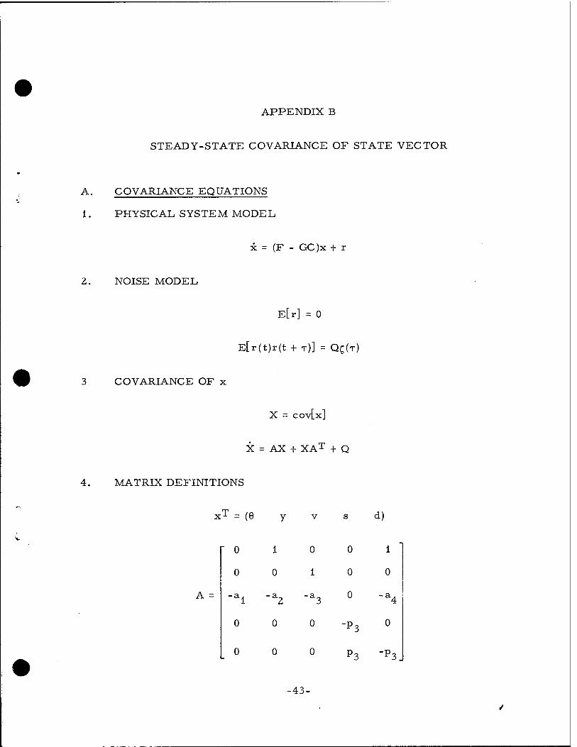
APPENDIX B
STEADY-STATE COVARIANCE OF STATE VECTOR
A. COVARIANCE EQUATIONS
1. PHYSIC AL S YS TE M MODE L
x = (F - GC )x + r
2. NOISE MODEL
E[r] = 0
E[r(t)r(t + T)] = QC(T)
3 COVARIANCE OF x
X = cov[xj
X = AX + XAT + Q
4. MATRIX DEFINITIONS
x = (9 y v s d)
0 1 0 0 1
0 0 1 0 0
al "a2 "a3 0 "a4
0 0 0 -*3
0
0 0 0 P3 -P3
-43-

X
Xll X12
X12 X22
Xi3 X23
X14 X24
X15 X25
X13 x14 x15
X23 x24
x 33
X34 x44
x 25
X34 x35
x 45
X3 5 x45 x55
0 0 0 0
0 0 0 0
0 0 2
p4q 0
0 0 0 2p3<
. o 0 0 0
0
0
al =P1C1 a2=Pl(C2+l) a3=p2 + PlC3 a4 = PlC2
B. SIMULTANEOUS LINEAR EQUATIONS FOR
STEADY-STATE COVARIANCE
2x, _, + 2x. _ = 0 12 15
x22+x25 + x13 = 0
X23 + x35 " alxll " a2X12 " a3X13 " a4X15 = °
-44-

x24 + x45 " P3X14 = °
X25 + X55 + P3(x14"x15) = 0
2x23 = 0
x33 " aix12 " a2x22 " a3X23 " a4x2 5 " °
X34 " P3X24 " °
X35 + P3(X24 " X25} = °
-2(a1x13 + a2x23 + a3x33 + a4x35) + p^ = 0
alX14 " a2X24 " a3X34 " a4X45 " P3X34 = °
p3(x34 - x35) - ajXjg - a2x25 - a^g - a4x55 - 0
"2P3X44 + 2p3 CT =0
2P3X45 + P3X44 = °
2p3(x45 - x55) = 0
■45-

C. SOLUTION TO STEADY-STATE COVARIANCE
This closed-form solution was derived and computer checked by
C. M. McKenzie. (The solution extends beyond the formulation given in the
text to include a white noise input with power spectral density q.)
X23 " 0
X44 = a2
a* X45 " 2
x44 2
0-2 £55 2 45
_ cr2(p^ + a3p3 + a2 - a4) x14 3 2 2(p3 + a3p3 + a2p3 + ap
o£ X24 ~ P3X14 " 2
X34 " P3X24
X14(p3 + a3P3 + a2p3) + a24(2p3 + a3P3> + X55(a3P3 + P3 + a2 " a4> Xl5 3 x 2 J. p3 + a3p3 + a2p3 + ajl
x25 " P3(X15 " X14) " X55
■46-

x35 " p3(x25 " x24)
x12 ~ "X15
x
2
ala3X12 " a4x35 + a3X25(a2 " a4)
13 al " a2a3
X22 " "X25 " X13
X33 ~ alX12 + a2X22 + a4X25
x x35 " a2X12 " a3X13 " a4x15
11
•47-
DISTRIBUTION
Internal
J. M. Bernard J. F. Bott R. A. Chodzko N. Cohen E. F. Cross D. A. Durran J. W. Ellinwood M. Epstein R. R. Giedt W. A. Griesser R. W. F. Gross R. A. Hartunian T. S. Hartwick R. F. Heidner J. M. Herbelin D. T. Hodges, Jr. R. Hofland, Jr. J. J. T. Hough M. A. Kwok
w. F. Lever ton p. Mahadevan H. Mirels G. A. Paulikas W. C. Riley S. Siegel A. H. Silver D. J. Spencer D. G. Sutton B. L. Taylor T. D. Taylor E. B. Turner R. L. Varwig C. P. Wang w. R. Warren, Jr K. R. Westberg J. S. Whittier M. T. Weiss R. L. Wilkins
External
SAMSO Lt. Col. Lindemuth (YCPT) Lt. A. Fernandez (YCPT) Lt. Col. J. R. Doughty (YD) Mr. G. E. Aichinger (TM)
AFWL Kirtand AFB, NM 87117
Col. J. Rieh (AR) Lt. Col. A. D. Maio (AL) Dr. P. Avizonis (AL) Capt. B. Crane (ALC) Dr. L. Wilson (ALC) Maj. D. Olson (ALC) Mr. L. Rapagnani (ALC)
DARPA 1400 Wilson Boulevard Arlington, VA 22209
Dr. H. A. Pike Dr. J. Mangano
AVCO-Everett Research Laboratory 2385 Revere Beach Parkway Everett, MA 02149
Dr. G. W. Sutton Dr. J. Dougherty

Science Applications, Inc. P.O. Box 328 5 Research Drive Ann Arbor, MI 48105
Dr. R. E. Meredith
Science Applications, Inc. 2 361 Jefferson Davis Highway- Arlington, VA 22202
Dr. W. R. Sooy
Lawrence Livermore Laboratory P.O. Box 808 Livermore, CA 94550
Dr. J. Emmett Dr. A. Karo
Arnold Engineering Development Center
Arnold Air Force Station, TN 37389 L.R. Case (XOOE)
ODUS DRE (R&AT) The Pentagon Washington, DC 20 301
Dr. G. P. Millburn, Rm 3E114
Deputy Undersecretary of Defense Tactical Warfare Programs The Pentagon Washington, DC 20301
Mr. R. A. Moore, Rm 3E1044
Deputy Undersecretary of Defense The Pentagon Washington, DC 20 301
Dr. S. Zeiberg, Rm 3E130
TRW Systems Group One Space Park Redondo Beach, CA 90278
Dr. J. Miller, 01/1080 Dr. D. Bullock Dr. J. Stansel Dr. C. W. Clendening, Jr.,
Bldg. Rl, Rm 1016 Dr. P. Clark
United Technologies Research Laboratories
400 Main Street East Hartford, CT 06108
Dr. J. Hinchen Dr. A. Angelbeck Dr. D. Seery Dr. C. Ultee
University of Maryland College Park, MD 20740 College of Engineering Department of Aerospace
Engineering Dr. J. D. Anderson, Jr.
Wright State University Dayton, OH 45431 Department of Chemistry
Dr. T. O. Tiernan Dr. G. D. Sides
University of Southern California Los Angeles, CA 90007 Department of Chemistry
Prof. S. W. Benson Department of Electrical Engineering
Prof. C. Wittig
University of California, San Diego La Jolla, CA 92703 Department of AMES
Prof. S. S. Penner Prof. S. C. Lin
University of Arizona Tucson, AZ 85721 College of Liberal Arts Department of Physics
Dr. G. Khayrallah, Bldg 181
IRIA Center ERIM P.O. Box 8618 Ann Arbor, Ml 48107

Bell Aerospace Textron P. O. Box 1 Buffalo, NY 14240
Dr. W. Solomon, Mail Zone B-49 Dr. J. Blauer, Mail Zone B-49 Dr. J. W. Raymonda,
Mail Zone B-49 Dr. R. J. Driscoll, Mail Zone B-49
California Institute of Technology- Pasadena, CA 91109
Prof. A. Kuppermann Prof. H. Liepmann Prof. A. Roshko
CALSPAN Corporation P.O. Box 235 Buffalo, NY 14221
Dr. J. Daiber Dr. C. E. Treanor
AFRPL (LKCG) Edwards AFB, CA 93523
B. R. Bornhorst
Los Alamos Scientific Laboratory Los Alamos, NM 87545
Dr. K. Boyer Dr. E. Brock Dr. G. Emanuel Dr. R. Jensen Dr. E. O'Hair Dr. J. Parker, Mail Station Dr. S. Rockwood
Deputy Chief of Staff for Research, Development and Acquisition
Department of the Army Headquarters The Pentagon Washington, DC 20 310
Lt C. B. J. Pellergrini, 3B482
US Army Missile Research and Development Command
Redstone Aresenal, AL 35809 Mr. J. M. Walters (DRDMI-HS) Dr. W. Wharton (DRSMI-RK) Dr. T. A. Barr, Jr (DRSMI-RH) Dr. D. Howgate
Columbia University Department of Chemistry New York, NY 10027
Dr. R. Zare
Michigan State University E. Lansing, MI 48824 Department of Mechanical Engineering
Dr.R. Kerber
Cornell University Ithaca, NY 14853 Department of Applied Physics
Dr. T. A. Cool Department of Chemistry
Dr. S. H. Bauer
Hughes Research Laboratory 3011 Malibu Canyon Road Malibu, CA 90265
Dr. A. Chester
General Electric Company U7211 VFSTC P.O. Box 8555 Philadelphia, PA 19101
R. Geiger J. Gilstein
Deputy Assistant Secretary of the Navy
Research and Advanced Technology The Pentagon Washington, DC 20350
Dr. T. A. Jacobs, Rm 4D 745 Dr. R. Hoglund, Rm 4D 745
Naval Research Laboratory 4550 Overlook Avenue SW Washington, DC 20375
Dr. W. S. Watt, Code 5540 Dr. J. M. MacCallum,
Code 5503 EOTP Dr. S. K. Searles, Code 5540
Naval Sea Systems Command Washington, DC 20362
Dr. D. Finkleman, PMS-40 5-20 Dr. L. Stoessell, PMS-405-30 Dr. J. A. Stregack, PMS-405-23 Capt. A. Skolnick, PMS-405
Hughes Aircraft Company Centinella and Teal Street Culver City, CA 90230
Dr. E. R. Peressini Dr. M. Mann
Lockheed Missiles and Space Company P.O. Box 1103, WestStation Huntsville, AL 35807
Dr. S. C. Kurzius
Lockheed Missiles and Space Company 4800 Bradford Blvd. Huntsville, AL 35812
J. W. Benefield
Mar tin-Marietta Denver, CO 80202
Dr. J. Bunting
Massachusetts Institute of Technology Cambridge, MA 02139 Department of Physics
Dr. A. Javan Department of Chemistry
Dr. J. Steinfeld
Naval Surface Weapons Center White Oak Laboratory Silver Springs, MD 20910
Dr. E. L. Harris, Code WA-13, Bldg 405, Rm 219
Commander Naval Weapons Center China Lake, CA 93555
E. Lunstrom, Code 4011 H. E. Bennett
NASA Lewis Research Center 21000 Brook Park Road Cleveland, OH 44135
S. Cohen, Mail Station 500-209
NASA Ames Research Center Moffett Field, CA 940 35
Dr. C. F. Hansen
Mathematical Sciences Northwest, Inc.
P.O. Box 1887 Bellevue, WA 98009
Dr. S. Byron Prof. A. Hertzberg P. Rose Dr. R. Center
McDonnell Douglas Corporation 5301 Bolsa Avenue Huntington Beach, CA 92647
Dr. R. Lee, Bldg. 28, Rm 250 Dr. W. A. Gaubatz
McDonnell Research Laboratory McDonnell Dougals Corporation St. Louis, MO 63166
Dr. D. P. Ames Dr. R. Haakinen Dr. D. Kelly
Northrop Corporation Research and Technology Center 1 Research Park Palos Verdes Peninsula, CA 90274
Dr. M. L. Bhaumik
RADC/ETSL Hanscom Air Force Base, MA 01731
Dr. H. Schlossberg
AFSC (DLS) Andrews AFB Washington, DC 20334

•
AFML (NA) Scientific and Technical Information Wright-Patterson AFB, OH 45433 Facility
P.O. Box 33 Air University Library- College Park, MD 20740 Maxwell AFB, AL 36112 NASA Representative
Air Force Office of Scientific Research RADC (XP) Boiling AFB, DC 20 332 Griffiss AFB, NY 13442
Directorate of Aerospace Sciences (NA) Electric Power Research Institute
Directorate of Physics (NP) P.O. Box 10412 Capt. Russell Armstrong Palo Alto, CA 94303
Dr. W. Gough Perkin-Elmer Corporation Dr. N. Amhert Norwalk, CN 06856
Electro-Optical Division Department of Energy M. L. Skolnick Washington, DC 20545
Division of Laser Fusion Physics International Company Dr. C. M. Stickley, Director 2700 Merced Street Dr. Paul Hoff San Leandro, CA 94577 Dr. J. Weiss
Dr. B. Bernstein Nuclear Research and Application Advanced Isotope Separation
Pratt and Whitney Aircraft Corporation Technology P.O. Box 2691 Dr. K. Hancock, Mail Station West Palm Beach, FL 33402 Mail Station H407
Dr. G. H. McLafferty, Mail Station B47 Purdue University
Mr. R. Oglukian, School of Mechanical Engineering Mail Station B47 Chaffee Hall
Lafayette, IN 47907 Princeton University Prof. J. G. Skifstad Princeton, NJ 08540 Department of Aerospace and Rockwell International Corporation Mechical Science Rocketdyne Division
Prof. S. Bogdonoff Canoga Park, CA 91304 Dr. S. V. Gunn
Rockwell International Corporation Dr. A. Axworthy Science Center Dr. E. Curtis 1049 Camino Dos Rios Dr. L. Zajac Thousand Oaks, CA 91360
Dr. A. T. Pritt, Jr. BDM Corporation 2600 Yale Boulevard SE
FJSRL (Tech Library) Albuquerque, NM 87106 USAF Academy, CO 80840 Dr. R. Rose

W. J. Schafer Associates, Inc. 901 N. Fort Myer Drive, Suite 803 Arlington, VA 22209
Dr. E. T. Gerry Dr. W. Evers
W. J. Schäfer Associates, Inc. 10 Lakeside Office Park Wakefield, MA 01880
Dr. J. Reilly
•


