
Phase Change Metallic Alloy TIM2 Performance, Reliability...
22
Phase Change Metallic Alloy TIM2 Performance, Reliability and Deployment J. McCullough, J. McCullough, C. Macris, R. Ebel, C. Leyerle C. Macris, R. Ebel, C. Leyerle Enerdyne Solutions Enerdyne Solutions www.enerdynesolutions.com www.enerdynesolutions.com Presented at IMAPS ATW ‘07 San Jose, California
Transcript of Phase Change Metallic Alloy TIM2 Performance, Reliability...

Phase Change Metallic Alloy TIM2 Performance, Reliability and Deployment
J. McCullough,J. McCullough, C. Macris, R. Ebel, C. LeyerleC. Macris, R. Ebel, C. Leyerle
Enerdyne Solutions Enerdyne Solutions www.enerdynesolutions.comwww.enerdynesolutions.com
Presented at IMAPS ATW ‘07 San Jose, California

September 26th, 2007September 26th, 2007 ©© 2007 Enerdyne Solutions2007 Enerdyne Solutions Page Page 22
OutlineOutline
�� PCMA & TIM2 OverviewPCMA & TIM2 Overview
�� TestingTesting
�� PerformancePerformance
�� ReliabilityReliability
�� Interface QualityInterface Quality
�� DeploymentDeployment
�� Next StepsNext Steps

September 26th, 2007September 26th, 2007 ©© 2007 Enerdyne Solutions2007 Enerdyne Solutions Page Page 33
PCMA OverviewPCMA OverviewWhat is a PCMA?What is a PCMA?
�� Phase Change Metallic Alloy or Low Melt Alloy (LMA)Phase Change Metallic Alloy or Low Melt Alloy (LMA)
�� Alloys of Indium, Bismuth, Gallium, TinAlloys of Indium, Bismuth, Gallium, Tin
�� Phase change typically 60Phase change typically 60--8080°°CC
�� Contains no organicsContains no organics
�� May have a composite layer structureMay have a composite layer structure
�� Typically in film/foil formTypically in film/foil form
�� High bulk conductivityHigh bulk conductivity
�� High degree of wetting yielding low contact resistanceHigh degree of wetting yielding low contact resistance

September 26th, 2007September 26th, 2007 ©© 2007 Enerdyne Solutions2007 Enerdyne Solutions Page Page 44
�� Reflow neededReflow needed�� PumpPump--outout�� MigrationMigration�� VoidingVoiding�� OxidationOxidation
�� High (metal) bulk conductivityHigh (metal) bulk conductivity�� Easy handlingEasy handling�� ReworkableReworkable
PhasePhase--Change Metal Change Metal Alloy (PCMA)Alloy (PCMA)
�� Cure neededCure needed�� Reflow neededReflow needed�� DelaminationDelamination�� NonNon--reworkablereworkable
�� Good bulk conductivityGood bulk conductivity�� Conforms to surface irregularitiesConforms to surface irregularities
PolymerPolymer--solder Hybrid solder Hybrid (PSH)(PSH)
�� PumpPump--outout�� Phase separationPhase separation�� MigrationMigration
�� High bulk conductivityHigh bulk conductivity�� Conforms to surface irregularitiesConforms to surface irregularities�� No cureNo cure�� ReworkableReworkable
Thermal GreaseThermal Grease
DisadvantagesDisadvantagesAdvantagesAdvantagesMaterialMaterial
Source: A. Source: A. DaniDani, J. , J. MatayabasMatayabas, P. , P. KoningKoning, , ““Thermal interface material technology advancements and challengeThermal interface material technology advancements and challengess——an overviewan overview””,,ASME ASME InterPACKInterPACK 2005, San Francisco, CA., July 172005, San Francisco, CA., July 17--22, 200522, 2005
TIM2 OverviewTIM2 OverviewHistoric QualitiesHistoric Qualities

September 26th, 2007September 26th, 2007 ©© 2007 Enerdyne Solutions2007 Enerdyne Solutions Page Page 55
TestingTesting——OOverviewverview
�� Packaged Thermal Test Vehicles (TTVs)Packaged Thermal Test Vehicles (TTVs)�� EOL performance dataEOL performance data
�� InIn--situ Test Vehicles (situ Test Vehicles (ITVsITVs))�� Reliability testingReliability testing

September 26th, 2007September 26th, 2007 ©© 2007 Enerdyne Solutions2007 Enerdyne Solutions Page Page 66
TestingTesting——Indigo test partIndigo test part36 mm
PCMA Region20 W/mK
Adhesive Seal0.2 W/mK
25 mm
2 mm
Indigo Interface Indigo Interface Dimensions:Dimensions:
�� Parts used for testing based on specific Parts used for testing based on specific customer implementationcustomer implementation
�� Indigo requires moderate clamping force Indigo requires moderate clamping force between heat sink and component between heat sink and component (~ 20psi)(~ 20psi)
�� BLT is between 3 and 4 MilsBLT is between 3 and 4 Mils
�� Indigo design includes adhesive sealIndigo design includes adhesive sealaround perimeter (~2mm)around perimeter (~2mm)
�� Studies show that heat distribution across Studies show that heat distribution across a heat spreader forms a bell curve a heat spreader forms a bell curve (majority of the heat near the center)(majority of the heat near the center)

September 26th, 2007September 26th, 2007 ©© 2007 Enerdyne Solutions2007 Enerdyne Solutions Page Page 77
TestingTesting——TTV PlatformTTV Platform

September 26th, 2007September 26th, 2007 ©© 2007 Enerdyne Solutions2007 Enerdyne Solutions Page Page 88
�� 4.84 cm4.84 cm22 die areadie area
�� 100 Watts100 Watts
�� 2 Mil BLT (shims)2 Mil BLT (shims)
�� Ni plated Cu lidNi plated Cu lid
�� Uniform heat fluxUniform heat flux
Ceramic TTVCeramic TTVfor Performance Data:for Performance Data:
TestingTesting——TTV DetailsTTV Details

September 26th, 2007September 26th, 2007 ©© 2007 Enerdyne Solutions2007 Enerdyne Solutions Page Page 99
~ 2046Thermal Conductivity (W/mK)
~60~30N/APhase Change Temperature (°C)
Indium-basedPCMA within
polymer
AL-filled polymer
Composition
Indigo2PSHParticle Grease
InIn--situ performance datasitu performance data
4040--50% reduction of 50% reduction of ΘΘJCJC
PerformancePerformance
ΘΘJCJC
0.0640.051
0.030
0
0.02
0.04
0.06
0.08
Particle Grease PSH Indigo2

September 26th, 2007September 26th, 2007 ©© 2007 Enerdyne Solutions2007 Enerdyne Solutions Page Page 1010
Clamping Bolts (4x)RTDs (2x Lid; 2x H2O block)TIM2 (Indigo2)Cu Lid
TIM1Heater (in place of die)Athlon XP (die removed)Athlon MB PCB (cut down)
RTD DAQ
Cooling Tank
HeaterPower Supply
COTS H20 Block
Pump
Chiller
Pump
ReliabilityReliabilityInIn--Situ Test Vehicle (ITV)Situ Test Vehicle (ITV)
Precision Compression Springs (30PSI on TIM2)

September 26th, 2007September 26th, 2007 ©© 2007 Enerdyne Solutions2007 Enerdyne Solutions Page Page 1111
ReliabilityReliabilityInIn--Situ Test Vehicle (ITV)Situ Test Vehicle (ITV)
�� Wells drilled into lid and Wells drilled into lid and waterblockwaterblock to to accommodate accommodate RTDsRTDs
�� 2 wells in lid, 2 in 2 wells in lid, 2 in waterblockwaterblock
�� Precision 4Precision 4--wire wire RTDsRTDs

September 26th, 2007September 26th, 2007 ©© 2007 Enerdyne Solutions2007 Enerdyne Solutions Page Page 1212
ReliabilityReliabilityInIn--Situ Test Vehicle (ITV)Situ Test Vehicle (ITV)
�� Vehicle Designed to Vehicle Designed to simulate specific clamping simulate specific clamping force and heat source force and heat source parameters during inparameters during in--situ situ reflowreflow
�� Replicates CTE and Replicates CTE and thermomechanicalthermomechanical forces forces on interface throughout on interface throughout environmental testingenvironmental testing
COTS COTS waterblockwaterblock
Athlon MBPCB cutout

September 26th, 2007September 26th, 2007 ©© 2007 Enerdyne Solutions2007 Enerdyne Solutions Page Page 1313
S. S. PecavarPecavar, D. Kearns, M. Stern, J. Dunn, V. , D. Kearns, M. Stern, J. Dunn, V. GektinGektin, B. , B. OngOng, T. Chen, , T. Chen, ““TIM2 Engineering TIM2 Engineering Qualification GuidelinesQualification Guidelines””, IMAPS Thermal ATW, 2005., IMAPS Thermal ATW, 2005.
Qualification Test Test Condition
Temperature Cycling
0°C to 100°C, 10°C/min. ramp, 10 min. dwell, 1000 cycles
Elevated Temp. Bake/Soak
125°C, 500 hrs
Temperature and Humidity
85°C/85% RH, 500hrs
Cold Cycle 24°C to -30°C, 10°C/min. ramp, 30 min. dwell, 3 cycles
ReliabilityReliabilityEnvironmental Test GoalsEnvironmental Test Goals

September 26th, 2007September 26th, 2007 ©© 2007 Enerdyne Solutions2007 Enerdyne Solutions Page Page 1414
�� JEDECJEDEC--J, J, 00--100100°°CC1000 Cycles1000 Cycles
�� Results for 2 Results for 2 partsparts
�� BLT is reduced BLT is reduced during first 100 during first 100 hot cycleshot cycles
�� Measurement Measurement error < 5% error < 5% between RTD, between RTD, meter and meter and comparative comparative measurementsmeasurements
ReliabilityReliabilityResultsResults--T/CT/C
% Change in ΘCS per TC Cycle
-10
-8
-6
-4
-2
0
2
4
6
8
10
0 200 400 600 800 1000
Thermal Cycles
% C
hang
e in
ΘC
S
September 26th, 2007September 26th, 2007 ©© 2007 Enerdyne Solutions2007 Enerdyne Solutions Page Page 1515
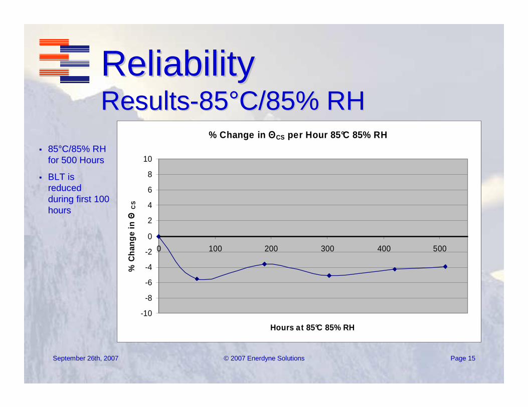
�� 8585°°C/85% RH C/85% RH for 500 Hoursfor 500 Hours
�� BLT is BLT is reduced reduced during first 100 during first 100 hourshours
ReliabilityReliabilityResultsResults--8585°°C/85% RHC/85% RH
% Change in ΘCS per Hour 85°C 85% RH
-10
-8
-6
-4
-2
0
2
4
6
8
10
0 100 200 300 400 500
Hours at 85°C 85% RH
% C
hang
e in
ΘC
S

September 26th, 2007September 26th, 2007 ©© 2007 Enerdyne Solutions2007 Enerdyne Solutions Page Page 1616
ReliabilityReliabilityResultsResults-- 125C Bake125C Bake
�� 125125°°C for 500 C for 500 HoursHours
�� BLT is BLT is reduced reduced initiallyinitially
�� Actual Actual degradation degradation from EOL from EOL (<1%)(<1%)
�� Minor Minor intermetallic intermetallic formationformation
% Change in ΘCS per Hour 125°C
-10
-8
-6
-4
-2
0
2
4
6
8
10
0 100 200 300 400 500
Hours at 125°C
% C
hang
e in
Θ
CS

September 26th, 2007September 26th, 2007 ©© 2007 Enerdyne Solutions2007 Enerdyne Solutions Page Page 1717
ReliabilityReliabilityResultsResults--Cold CycleCold Cycle
�� Cold CycleCold Cycle
�� --30 to 2430 to 24°°C, C, 1010°°C/min rampC/min ramp30 min dwell30 min dwell3 cycles total3 cycles total
�� 0.6% change in 0.6% change in ΘΘCSCS within within measurement measurement errorerror
% Change in ΘCS After Cold Cycles
0
0
0
0
0
1
1 2
ΘC
S
EOL
ΘCS = 0.0302
After Cold Cycles
ΘCS = 0.0304

September 26th, 2007September 26th, 2007 ©© 2007 Enerdyne Solutions2007 Enerdyne Solutions Page Page 1818
�� Typical void fraction Typical void fraction < 2%< 2%
�� On close On close examination of examination of surface, texture of lid surface, texture of lid and heat sink visible and heat sink visible on interface surfaceon interface surface
Interface QualityInterface QualityVoid FractionVoid Fraction——EOLEOL
Corner torn during ITV disassemblyCorner torn during ITV disassembly
Interface removed from ITV at EOLInterface removed from ITV at EOL

September 26th, 2007September 26th, 2007 ©© 2007 Enerdyne Solutions2007 Enerdyne Solutions Page Page 1919
Test joint break load for a range of TIM types
M. Stern, D. Kearns, B. M. Stern, D. Kearns, B. OngOng, , ““Adhesion of Thermal Interface Materials for Adhesion of Thermal Interface Materials for CpuCpuHeatsinksHeatsinks, an Overlooked Issue, an Overlooked Issue””, Electronics Cooling Magazine, Feb. 2007. , Electronics Cooling Magazine, Feb. 2007.
36 mm
40 mm
25 mm
�� 1.5 in1.5 in 22 component areacomponent area
�� Ambient temperatureAmbient temperature
�� 7 lbs/min. ramp (tensile loading)7 lbs/min. ramp (tensile loading)
�� 23.3 psi (160 23.3 psi (160 kPakPa) break load) break load
�� Similar to PCM >Similar to PCM > TmeltTmelt
DeploymentDeploymentReworkabilityReworkability
0
100
200
300
400
500
600
700
800
900
D r y F i l m P a d
G r e a s e 1P u t t
yI n d i g o 2
G r e a s e 2P C M >
T m e l tP C M <
T m e l t
Bre
ak L
oad
(kP
a)
Loaded Area: 25 x 25 mm

September 26th, 2007September 26th, 2007 ©© 2007 Enerdyne Solutions2007 Enerdyne Solutions Page Page 2020
Next StepsNext Steps
�� Shock/Vibe TestingShock/Vibe Testing�� Corroborate existing data with Corroborate existing data with
larger lot sizelarger lot size�� Extend proven architecture to new Extend proven architecture to new
applications: Lasers, power applications: Lasers, power semiconductors, RF amplifiers, semiconductors, RF amplifiers, microprocessors, etc.microprocessors, etc.

September 26th, 2007September 26th, 2007 ©© 2007 Enerdyne Solutions2007 Enerdyne Solutions Page Page 2121
PCMA TIM2 SummaryPCMA TIM2 Summary
�� Design meets performance goal of Design meets performance goal of 4040--50% 50% reduction of reduction of ΘΘCSCS over greases or over greases or PSHsPSHs�� Qualifies TIM2 environmental testing Qualifies TIM2 environmental testing �� Void fraction <2%Void fraction <2%�� Historic disadvantages of Historic disadvantages of PCMAsPCMAs have been have been
overcomeovercome�� ReworkableReworkable�� Scalable to other applicationsScalable to other applications

September 26th, 2007 © 2007 Enerdyne Solutions 22
Thank you.
John McCulloughEnerdyne SolutionsNorth Bend, WA USA


![1 Introduction to the Science of Complex Metallic Alloys · Complex metallic alloys (or CMA for short), also called SCAPs (for structurally complex alloy phases) for some time [1]](https://static.fdocuments.net/doc/165x107/5f217b2c32e27a58f3493217/1-introduction-to-the-science-of-complex-metallic-complex-metallic-alloys-or-cma.jpg)


