Phase 1 Report - cpb-us-w2.wpmucdn.com · 2 Introduction: For Team FSAE Suspension, phase 4 was...
20
Phase 4 Report MEEG401: Team FSAE Suspension December 10, 2010
Transcript of Phase 1 Report - cpb-us-w2.wpmucdn.com · 2 Introduction: For Team FSAE Suspension, phase 4 was...
Phase 4 Report MEEG401: Team FSAE Suspension
December 10, 2010

2
Introduction:
For Team FSAE Suspension, phase 4 was largely spent in the student machine shop. The final
design selected during phase 2, and developed in detail during phase 3, was manufactured and
installed. Many hours were spent in the manufacture of the components of the proposed
suspension system. The result of this semester’s work is the research, concept generation,
concept selection, and concept implementation of a successful unequal a-arm independent
suspension for the 2010 UD FSAE race car. The final touches are still being made to the
assemblies, but the components have been manufactured, and for the most part installed on
the new car’s chassis, and will shortly be subjected to testing and performance evaluation. The
completed design package includes Uprights, A-Arms, Push Rods, Tie Rods, Rockers, Shock
Absorbers, Sway Bars, and all of the clevises, mounting tabs and hardware needed to assemble
and test the suspension. During the final few days remaining before the deliverables are due to
the sponsor, the team intends to continue with the testing further defined in this report, and
will pursue ongoing work with the FSAE club during the winter session and spring semester to
continue to test and tune the car’s suspension.
Final Design Description:
Suspension Style: The unequal a-arm suspension was chosen by the suspension team as the design concept to be
pursued during phase two. The A-arm configuration meets the design requirements for
structural integrity and suspension travel, and benchmarking specific to FSAE indicated that the
Unequal A-arm design was by far the most common design in FSAE application. The chosen
design concept utilizes similar components for front, back, top and bottom control arms, which
will provide a high level of standardization of parts and components, and the similarity to the
prior car's design will enable easy use of components such as shocks and springs from previous
cars. Each control arm has been manufactured with a few simple welding and machining
operations, and the final dimensions of the upper and lower arms across all four corners of the
car have been standardized so that two configurations, top a-arm and bottom a-arm, are
similar. Other parts such as rockers, pushrods and clevises have been made as uniform as
possible to keep the number of discrete parts as low as possible.
The unequal a-arm suspension system is comprised of upper and lower V shaped frames
attached to the chassis in four specified suspension mounts with spherical bearings to provide
one degree of freedom. Each arm provides an attachment point for the wheel upright that is
fixed in two dimensions (laterally and longitudinally to the chassis) and free to move in the third

3
dimension (vertically). The upper and lower arms are designed with different lengths and
mount points, with the shorter arm installed above the longer arm. This geometry provides a
change in camber as the suspension components move through the range of travel. The design
lengths have been optimized through the kinematic analysis to provide the desired cambering
behavior.
The suspension arms are supported by a push rod assembly that resists the motion associated
with the suspension travel, and supports the weight of the car in its neutral position. The push
rod attaches at the base of the wheel upright, and travels diagonally upward to an attachment
to a rocker. The rocker is affixed to the chassis, and transfers the force in the push rod to a
shock absorber and spring assembly that both dampens, and supports the travel of the
suspension system, and to a pushrod that actuates the sway bars during body roll.
Figure 1: Upper and Lower A-arms
Adjustability: One of the most important details that the sponsor emphasized for the design of the
suspension was adjustability. After careful consideration of the advantages and disadvantages
of each of the adjustability concepts discussed in the previous section of this report, three
stood out as the most promising: the threaded chassis mount, slotted chassis clevis, and upright
shims. These three ideas work in conjunction in the suspension system to achieve the desired
degree of adjustability. The merits of the three concepts are discussed below.
Threaded Rod End
This concept achieves adjustability in the a-arm length. The rod end is easily accessed by
removing a bolt and screwing it in or out to adjust the a-arm length. Additionally, the same
process can used to fine tune the caster angle. This concept did the best job of avoiding
weakness in the a-arm. It keeps the a-arm solid, with only a threaded insert at the end. This
design moves the weakness of the suspension to the bolts. If the bolts should fail, they are
easily replaced and we save the more important components like the a-arms. Team FSAE
suspension is confident that this will not become a problem. This concept is one of the easiest
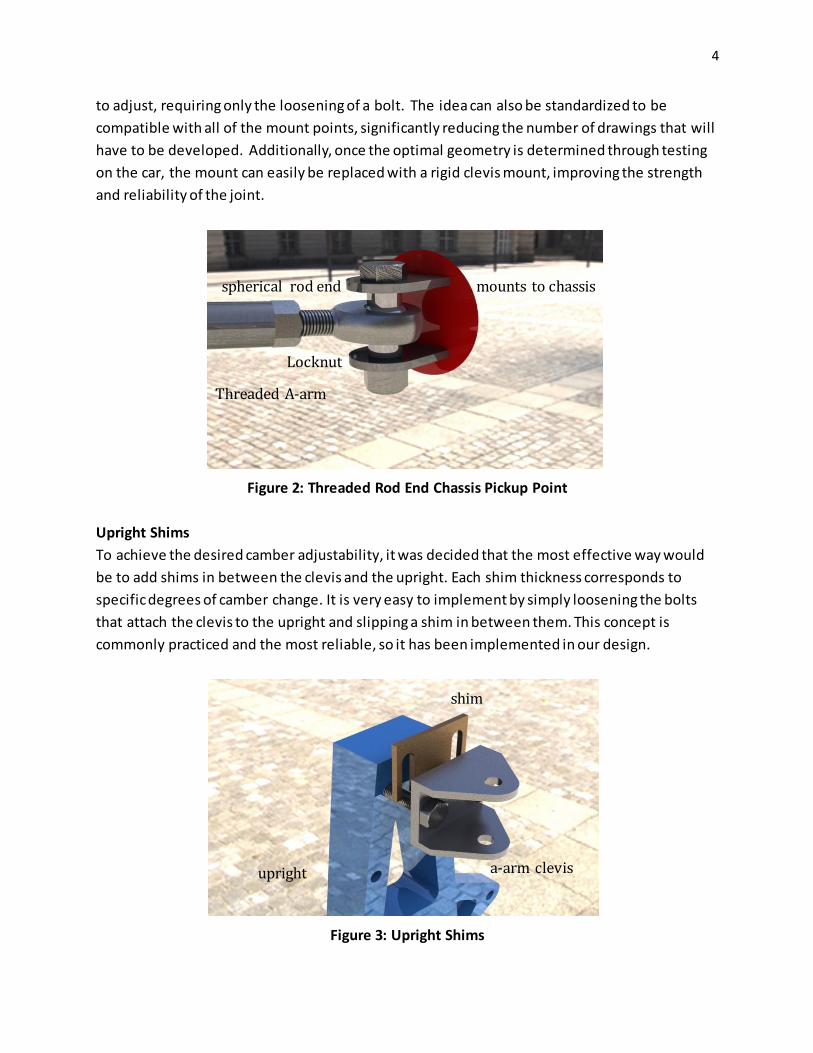
4
to adjust, requiring only the loosening of a bolt. The idea can also be standardized to be
compatible with all of the mount points, significantly reducing the number of drawings that will
have to be developed. Additionally, once the optimal geometry is determined through testing
on the car, the mount can easily be replaced with a rigid clevis mount, improving the strength
and reliability of the joint.
Figure 2: Threaded Rod End Chassis Pickup Point
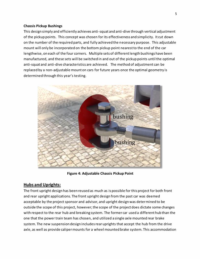
Upright Shims
To achieve the desired camber adjustability, it was decided that the most effective way would
be to add shims in between the clevis and the upright. Each shim thickness corresponds to
specific degrees of camber change. It is very easy to implement by simply loosening the bolts
that attach the clevis to the upright and slipping a shim in between them. This concept is
commonly practiced and the most reliable, so it has been implemented in our design.
Figure 3: Upright Shims
Threaded A-arm
mounts to chassis spherical rod end
Locknut
upright a-arm clevis
shim
5
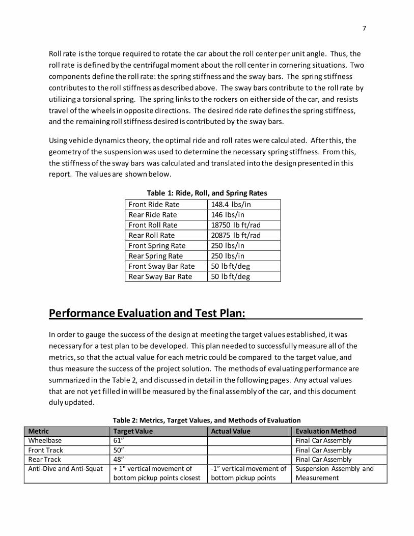
Chassis Pickup Bushings
This design simply and efficiently achieves anti-squat and anti-dive through vertical adjustment
of the pickup points. This concept was chosen for its effectiveness and simplicity. It cut down
on the number of the required parts, and fully achieved the necessary purpose. This adjustable
mount will only be incorporated on the bottom pickup point nearest to the end of the car
lengthwise, on each of the four corners. Multiple sets of different length bushings have been
manufactured, and these sets will be switched in and out of the pickup points until the optimal
anti-squat and anti-dive characteristics are achieved. The method of adjustment can be
replaced by a non-adjustable mount on cars for future years once the optimal geometry is
determined through this year’s testing.
Figure 4: Adjustable Chassis Pickup Point
Hubs and Uprights: The front upright design has been reused as much as is possible for this project for both front
and rear upright applications. The front upright design from the past car was deemed
acceptable by the project sponsor and advisor, and upright design was determined to be
outside the scope of this project, however; the scope of the project does dictate some changes
with respect to the rear hub and breaking system. The former car used a different hub than the
one that the power train team has chosen, and utilized a single axle mounted rear brake
system. The new suspension design includes rear uprights that accept the hub from the drive
axle, as well as provide caliper mounts for a wheel mounted brake system. This accommodation
bushing
bushing

6
has been made by modifying the front upright design (that already includes caliper mounts) to
receive the rear hub. The specific hub and bearing configuration has been chosen by the
drivetrain team, and the suspension team has accommodated by modifying the existing upright
design.
Figure 5: Front and Rear uprights
Shocks and Springs:
As per the customer and advisor recommendations, the Fox shocks already owned by the UD
FSAE club have been utilized in the design. Springs of varying stiffnesses are readily available for
these shocks, so the appropriate springs have been selected and purchased. Using vehicle
dynamics theory, as researched from an authoritative text on the topic, Race Car Vehicle
Dynamics, Milliken and Milliken, the desired ride and roll rates were found. Ride rate is defined
as the force required to make the wheel travel upwards per unit of distance. It defines not only
the travel of the suspension and the vertical movement of the chassis, but also the roll
characteristics of the car through the associated spring rate. As the car rolls, it causes the
outside wheel to travel upwards due to the centrifugal moment about the roll center. The
stiffness of the springs directly affects how much the car can roll.
7
Roll rate is the torque required to rotate the car about the roll center per unit angle. Thus, the
roll rate is defined by the centrifugal moment about the roll center in cornering situations. Two
components define the roll rate: the spring stiffness and the sway bars. The spring stiffness
contributes to the roll stiffness as described above. The sway bars contribute to the roll rate by
utilizing a torsional spring. The spring links to the rockers on either side of the car, and resists
travel of the wheels in opposite directions. The desired ride rate defines the spring stiffness,
and the remaining roll stiffness desired is contributed by the sway bars.
Using vehicle dynamics theory, the optimal ride and roll rates were calculated. After this, the
geometry of the suspension was used to determine the necessary spring stiffness. From this,
the stiffness of the sway bars was calculated and translated into the design presented in this
report. The values are shown below.
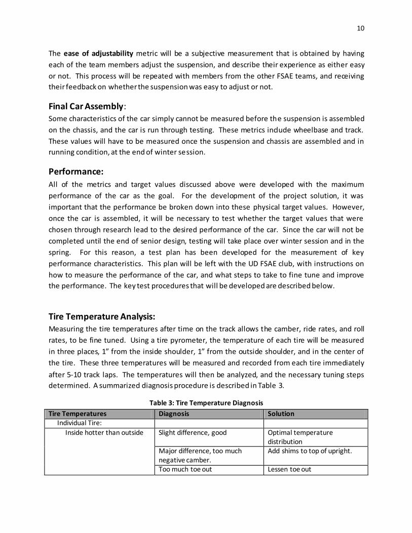
Table 1: Ride, Roll, and Spring Rates
Front Ride Rate 148.4 lbs/in
Rear Ride Rate 146 lbs/in
Front Roll Rate 18750 lb ft/rad
Rear Roll Rate 20875 lb ft/rad
Front Spring Rate 250 lbs/in
Rear Spring Rate 250 lbs/in
Front Sway Bar Rate 50 lb ft/deg
Rear Sway Bar Rate 50 lb ft/deg
Performance Evaluation and Test Plan:
In order to gauge the success of the design at meeting the target values established, it was
necessary for a test plan to be developed. This plan needed to successfully measure all of the
metrics, so that the actual value for each metric could be compared to the target value, and
thus measure the success of the project solution. The methods of evaluating performance are
summarized in the Table 2, and discussed in detail in the following pages. Any actual values
that are not yet filled in will be measured by the final assembly of the car, and this document
duly updated.
Table 2: Metrics, Target Values, and Methods of Evaluation
Metric Target Value Actual Value Evaluation Method Wheelbase 61” Final Car Assembly
Front Track 50” Final Car Assembly Rear Track 48” Final Car Assembly Anti-Dive and Anti-Squat + 1" vertical movement of
bottom pickup points closest -1” vertical movement of bottom pickup points
Suspension Assembly and Measurement

8
to CoG of car farthest from CoG of car Roll Center Stable, < 1" vertical
movement over 1.5” deflection in roll, ~3” height at neutral
---- Suspension Assembly and Measurement
Scrub Radius Minimize, <1” Suspension Assembly and Measurement
Camber -2: static, maintained over 0.5” deflection in roll
---- Suspension Assembly and Measurement
Kingpin Angle 0-5 degrees 0 degrees Suspension Assembly and Measurement
Caster Angle 0-5 degrees Suspension Assembly and Measurement
Center of Gravity Longitudinal: centered Lateral: centered Height: ≤ 10”
F/R Weight Distribution 50/50 Spring Stiffness TBD 250 lbs/in Damped Frequency TBD 3 – 3.5 Hz
# Tools to Adjust 3 3 (2 x 7/16 wrenches and 1 x 9/16 wrench)
Suspension Assembly and Measurement
Adjustments easy to access
Yes Yes (judged by all team members)
Suspension Assembly and Measurement
Camber and Toe adjustment without disconnection of parts
Yes Yes Suspension Assembly and Measurement
Material Strength Factor of safety >2 for range of normal operation
FOS >5 for range of normal operation
Material Machinability Maximize maximized
Material Cost Minimize Within budget Material Weight Minimize Minimized for material
Suspension Assembly and Measurement:
For the FSAE suspension, the most important metrics are related to the geometry. For this
reason, it is important that the suspension be fully assembled, so that these geometric metrics
can be measured. Since the suspension is still in the process of bei ng assembled on the chassis,
not all of the final values have been measured as of yet. One corner of the suspension can now
be fully assembled for testing. A poster board will be fixed to the front side of the suspension
box, so that instant centers and other geometric features can be marked. With the corner
assembled, the relevant metrics will be measured.
In order to meet the target value for anti-dive and anti-squat, the length of the switchable
bushings is all that must be known. This was measured, using the distance between the tabs of
the pickup point, the width of the rod end, and the variety of bushings that can be made.

9
Measuring the roll center position will be slightly more difficult. The suspension will be set in
the neutral stance position, and the front-view instant center position constructed from the
geometry and marked on the poster board. The line from the instant center to the tire contact
patch will then be drawn, and assuming symmetry in the neutral stance, the roll center will be
marked on the board. The suspension will then be set at the 0.5” jounce position, and the
instant center reconstructed and marked. Since the roll center cannot be constructed from
only one corner when the suspension is not symmetrically deflected, the instant center position
of the one corner will be measured and compared the values calculated in the kinematic
analysis to confirm the predicted movement. If the values do not match, further steps will be
taken to assemble both sides of the suspension and physically measure the roll center
movement.
Measuring scrub radius will be a simple matter of measurement once the upright, clevis and
wheels are assembled. The steering axis will be measurable from the clevises, and the distance
between it and the wheel centerline at the contact patch will be easily constructed and
compared to the simulated values. Unfortunately, this metric could not be significantly
affected by any changes the team could make. The primary contributors to scrub radius are the
front hubs, which were outside the scope of the project. This is the reason for this target value
not meeting the goal value.
The Camber is a critical measurement of the jig assembly. With the suspension set in the
neutral stance, the camber angle will be measured by tracing the upright angle onto the poster
board, and drawing and intersecting vertical line using a plumb. The angle between the two
lines will then be measured. The suspension will next be set in the 0.5” jounce position, and
the previous angle construction repeated. This new angle will be subtracted from the
measured change in bottom a-arm angle to obtain the net camber change. The process will be
repeated in the 0.5” rebound position.
Kingpin angle was obtained by measuring the difference between the upright angle and the
line between the two clevis centers, which constructs the steering axis. Since the upright
clevises were all the same size, the kingpin angle as zero.
To obtain caster angle, the side-view line between the top and bottom upright spherical joints,
and then measuring the angle between this line and a vertical line constructed using a plumb.
The caster angle will then be adjusted as necessary by changing the lengths of each arm in the
a-arms until the desired angle is obtained.
The number of tools required to adjust the suspension was easily measured from the
suspension assembly, simply by noting how many tools were needed to adjust the key
adjustability components of the suspension as it is assembled on the chassis.
10
The ease of adjustability metric will be a subjective measurement that is obtained by having
each of the team members adjust the suspension, and describe their experience as either easy
or not. This process will be repeated with members from the other FSAE teams, and receiving
their feedback on whether the suspension was easy to adjust or not.
Final Car Assembly: Some characteristics of the car simply cannot be measured before the suspension is assembled
on the chassis, and the car is run through testing. These metrics include wheelbase and track.
These values will have to be measured once the suspension and chassis are assembled and in
running condition, at the end of winter session.
Performance:
All of the metrics and target values discussed above were developed with the maximum
performance of the car as the goal. For the development of the project solution, it was
important that the performance be broken down into these physical target values. However,
once the car is assembled, it will be necessary to test whether the target values that were
chosen through research lead to the desired performance of the car. Since the car will not be
completed until the end of senior design, testing will take place over winter session and in the
spring. For this reason, a test plan has been developed for the measurement of key
performance characteristics. This plan will be left with the UD FSAE club, with instructions on
how to measure the performance of the car, and what steps to take to fine tune and improve
the performance. The key test procedures that will be developed are described below.
Tire Temperature Analysis: Measuring the tire temperatures after time on the track allows the camber, ride rates, and roll
rates, to be fine tuned. Using a tire pyrometer, the temperature of each tire will be measured
in three places, 1” from the inside shoulder, 1” from the outside shoulder, and in the center of
the tire. These three temperatures will be measured and recorded from each tire immediately
after 5-10 track laps. The temperatures will then be analyzed, and the necessary tuning steps
determined. A summarized diagnosis procedure is described in Table 3.
Table 3: Tire Temperature Diagnosis
Tire Temperatures Diagnosis Solution Individual Tire:
Inside hotter than outside Slight difference, good Optimal temperature distribution
Major difference, too much negative camber.
Add shims to top of upright.
Too much toe out Lessen toe out
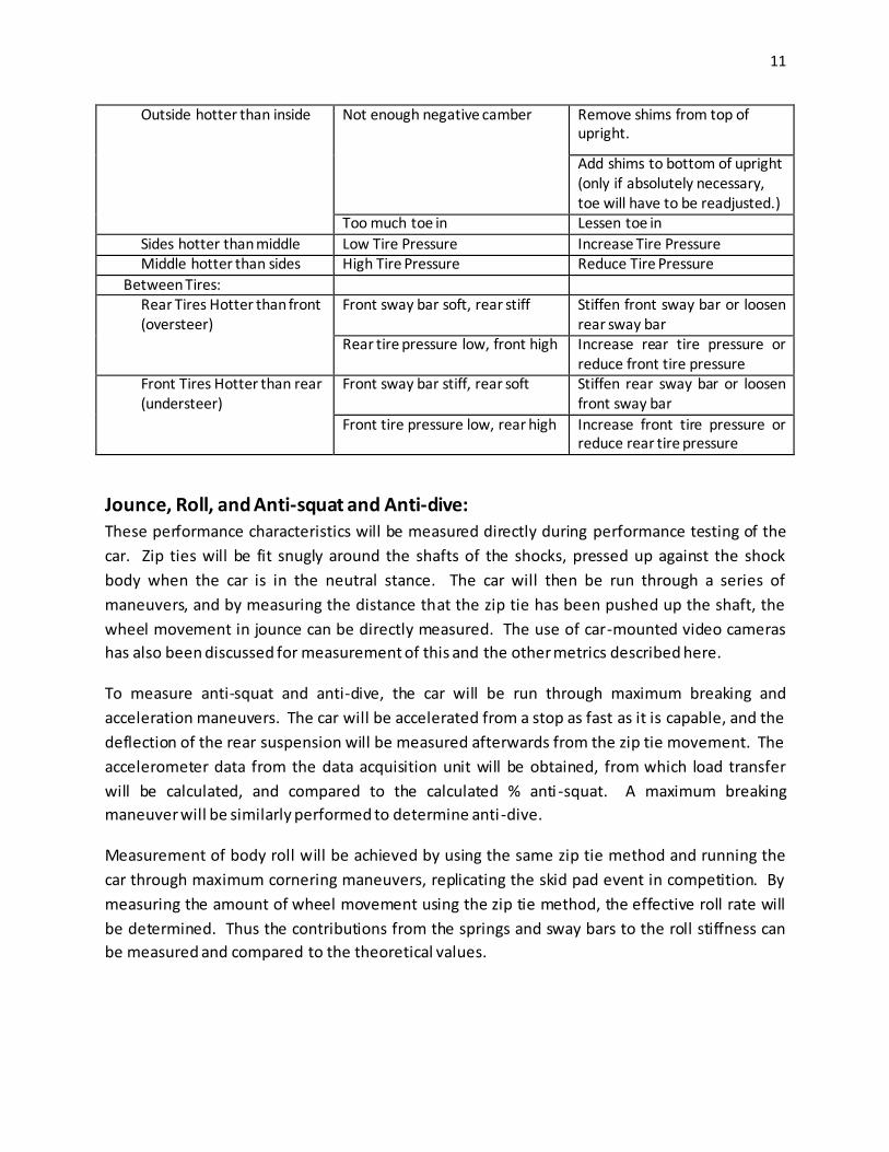
11
Outside hotter than inside Not enough negative camber Remove shims from top of upright.
Add shims to bottom of upright (only if absolutely necessary, toe will have to be readjusted.)
Too much toe in Lessen toe in
Sides hotter than middle Low Tire Pressure Increase Tire Pressure Middle hotter than sides High Tire Pressure Reduce Tire Pressure
Between Tires: Rear Tires Hotter than front (oversteer)
Front sway bar soft, rear stiff Stiffen front sway bar or loosen rear sway bar
Rear tire pressure low, front high Increase rear tire pressure or reduce front tire pressure
Front Tires Hotter than rear (understeer)
Front sway bar stiff, rear soft Stiffen rear sway bar or loosen front sway bar
Front tire pressure low, rear high Increase front tire pressure or reduce rear tire pressure
Jounce, Roll, and Anti-squat and Anti-dive: These performance characteristics will be measured directly during performance testing of the
car. Zip ties will be fit snugly around the shafts of the shocks, pressed up against the shock
body when the car is in the neutral stance. The car will then be run through a series of
maneuvers, and by measuring the distance that the zip tie has been pushed up the shaft, the
wheel movement in jounce can be directly measured. The use of car-mounted video cameras
has also been discussed for measurement of this and the other metrics described here.
To measure anti-squat and anti-dive, the car will be run through maximum breaking and
acceleration maneuvers. The car will be accelerated from a stop as fast as it is capable, and the
deflection of the rear suspension will be measured afterwards from the zip tie movement. The
accelerometer data from the data acquisition unit will be obtained, from which load transfer
will be calculated, and compared to the calculated % anti -squat. A maximum breaking
maneuver will be similarly performed to determine anti -dive.
Measurement of body roll will be achieved by using the same zip tie method and running the
car through maximum cornering maneuvers, replicating the skid pad event in competition. By
measuring the amount of wheel movement using the zip tie method, the effective roll rate will
be determined. Thus the contributions from the springs and sway bars to the roll stiffness can
be measured and compared to the theoretical values.

12
The test plan outlined above will be submitted to the UD FSAE club as an independent
document, to be kept in the club and used during the testing of the car, both by other club
members and the members of the club in this senior design group.
Transition:
As our official responsibility for the project ends on the 17th when the deliverables are
presented to the sponsor, the importance of the transition to the UD FSAE club becomes very
important. The test plan given above, and attached separately, will be a primary way that the
team’s understanding of the suspension will be passed on to the club. Additionally,
participation of the team members within the club during the winter and spring will be
important. Our involvement in the club will foster the transfer of knowledge about the
suspension from the team to the club, preparing the junior club members for the potential
senior design project in 2011. During the spring semester, team involvement in the club will
help to test the durability of the suspension and tune it to its best performance. In the
summer, at least a few of the team members will be seeking to travel to California for
competition. This will be important for success in the static events, particularly the design
event. To assist with this transitional process, and at the suggestion of the advisor, a list of tasks
to be completed by the club is given here:
Complete manufacturing of bushings. All of the different types of bushings have been manufactured, but not as many of each as are needed. These simple bushing simply need to be manufactured on an as-needed basis to complete the assembly of the
suspension system. This includes primarily: o Bushing for the joints between the rockers and the pushrods, shocks, and sway
bar linkages.
o Bushings for the points where the shocks are mounted to the chassis.
One of the front uprights needs to have its center hole milled out to match the larger diameters of the other front upright.
The travel of the suspension needs to be confirmed (jounce and rebound), once the car
is fully assembled. Due to rounded weld joints that were not accounted for in the solid model, the bottom edges of the top a-arms may need to be ground down at the upright side.
Due to chassis/drivetrain complications over the location of the drive chain, the frame
member that the rear shocks are mounted to may need to be moved. The shock mounts and possibly the rear rocker mounts may need to be altered to fit the new frame members.
The full welding of all the tacked suspension/frame joints needs to be completed.
For suspension pickup points on chassis, C-shaped side gussets need to be cut and welded to the pickup tabs.
13
All aluminum suspension components should be anodized and all steel components powder-coated.
Voids in the a-arms created by the parallel gusset plates need to be filled with foam or
capped to prevent debris filling the voids.
Nut faces should be added to the pushrods, tie rods, and sway bar linkages, to make adjustment easier. This can be achieved by drilling out the center of a nut, sliding it over the tube of the rod, and welding it in place.
When shims are manufactured for the uprights, they need to have tabs on the top or sides to make addition and removal of tabs easier.
For the adjustable anti-dive and anti-squat pickup points, multiple bushing sets should be made, to allow adjustment of the rod end up and down in ¼” increments.
Push/Pull testing should be performed on duplicate components of the adjustable anti pickup points, to validate the strength of the points.
Conclusion:
Team FSAE Suspension is glad to have reached completion of this project. At the beginning of
the semester, we knew close to nothing. Now, as we finish up the project, we are confident in
our knowledge of formula-style suspension, in theory and with some experience in practice.
The project began with an extensive amount of research, to educate the team and to develop
key metrics and target values. The sponsor and advisor were invaluable in this process,
providing a large amount of in-depth information on suspension and its workings. Moving
forward from metrics and target values, concepts were proposed and analyzed, until the top
ideas had been sorted out and developed. From there, the concepts were developed into
detailed designs, with the end result of component and assembly drawings in preparation for
manufacturing. Phase 4 was almost entirely consumed with manufacturing and fabrication,
transforming the CAD models and drawings into real parts. This required a lot of growth among
the team members in machining and welding ability. The team considers the project a success,
as all the parts have been manufactured, and by the 17th, it will all be finally attached to the
chassis. Testing and tuning in the winter and spring will confirm the performance
characteristics of the car, and the team is confident that the results will be positive and as
expected.
In conclusion, Team FSAE Suspension has enjoyed the opportunity to participate in the FSAE
sections of senior design. The project assigned us was very in-depth and involved, and possibly
too much to be realistic for one semester, especially considering the amount of manufacturing
involved. However the team was able to complete the project on schedule, with a design that
meets the target values and goals set forward at the beginning of the project, while also staying
within the constraints imposed on us. Many thanks are due to Dr. Steven Timmins, our advisor,
who provided oversight of the project, along with huge amounts of help through suggestions

14
and discussions of concepts and theory. We are also indebted to Steve Beard and Al Lance,
who patiently helped us with manufacturing, and worked late to provide us with evening hours,
respectively. Moving forward, the team is confident in the future success of the suspension,
and looks forward to staying involved over the winter and spring, and proceeding to a
successful trip to competition at the beginning of the summer.

15
APPENDIX
UD FSAE
Suspension Testing and Tuning
Instruction Manual
Senior Design Team FSAE Suspension
December 10, 2010

16
Introduction:
Over the course of the senior design class of Fall 2010, the FSAE Suspension team developed
the suspension system used on the 2010 UDFSAE car. Due to the nature of the course, and the
depth of the project, fabrication of all of the car’s system was finished only days before the
deliverables deadline at the end of the semester. For this reason, the team was not able to
complete any kind of performance evaluation of the suspension system. This manual outlines a
set of test procedures intended to evaluated the performance characteristics of the suspension,
and provide guidelines for tuning the suspension to achieve maximum performance.
Purpose:
All of the geometry-related metrics and target values developed during senior design were
intended to maximize performance. Appropriate camber, ride and roll rates, and anti -dive and
anti-squat all serve to improve the performance of the car on the track. Theoretical target
values were developed during the semester, all with the goal of giving the car the best possible
performance. However, to actually achieve the best performance, it is necessary to tune the
adjustable parts of the car based on the results of testing and driving. The purpose of this
manual is to give some direction to the tuning of the car, making it easier to achieve optimal
performance.
Equipment:
1. Tire Pyrometer
2. Zip Ties
3. Video Camera – preferably car-mounted
4. 1 9/16 wrench
5. 2 7/16 wrenches
Procedures:
Ride Height:
To adjust the ride height of the car:
1. Using a 9/16” wrench, loosen the jam nuts on either end of the push rods.

17
2. Turn the pushrods to either lengthen the pushrods to raise the ride height, or
shorten the pushrods to lower the ride height.
3. Retighten the jam nuts.
4. If the incorrect ride height is caused by the shocks being excessively
compressed, or not compressed enough, adjust the preload on the shocks as
necessary.
5. Make sure to keep the ride height the same from side to side. Front to back
can be different as desired.
Static Camber:
To adjust the static camber of the car at ride height:
1. Using the two 7/16” wrenches, loosen the two bolts on the top a-arm clevis at
the top of the upright.
2. Insert shims as necessary to add to the camber, or remove them to remove
positive camber.
3. If more negative camber is desired than be achieved by removing all the shims,
loosen the bolts at the bottom of the upright and add shims.
4. Retighten all the bolts.
Toe:
To adjust the toe of the wheels
1. Using the 9/16” wrench, loosen the jam nuts on either end of the tie rod.
2. Turn the tie rod as necessary to lengthen or shorten it, and toe out or in.
3. Retighten the jam nuts.
Tire Temperature Analysis: Measuring the tire temperatures after time on the track allows the camber, ride rates,
and roll rates, to be fine tuned. To perform a tire temperature analysis, complete the
following steps:
1. Bring the tires up to operating temperature by driving the car. Perform
several laps of the test course.
2. Immediately after performing the tire warm-up, use the tire pyrometer to
measure the tire temperature as shown in Figure 1. Measure in three places:
1” from the inside shoulder of the tire, 1” from the outside shoulder, and in the
center of the tire.
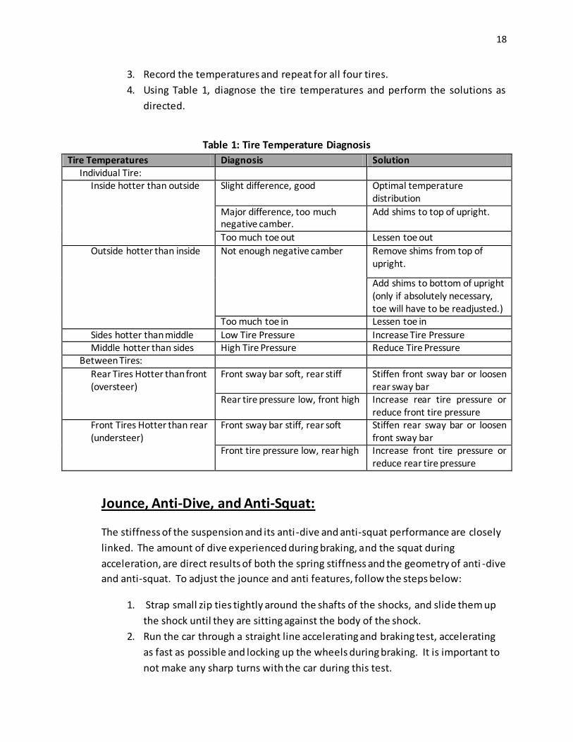
18
3. Record the temperatures and repeat for all four tires.
4. Using Table 1, diagnose the tire temperatures and perform the solutions as
directed.
Table 1: Tire Temperature Diagnosis
Tire Temperatures Diagnosis Solution Individual Tire: Inside hotter than outside Slight difference, good Optimal temperature
distribution
Major difference, too much negative camber.
Add shims to top of upright.
Too much toe out Lessen toe out
Outside hotter than inside Not enough negative camber Remove shims from top of upright.
Add shims to bottom of upright (only if absolutely necessary, toe will have to be readjusted.)
Too much toe in Lessen toe in
Sides hotter than middle Low Tire Pressure Increase Tire Pressure Middle hotter than sides High Tire Pressure Reduce Tire Pressure Between Tires:
Rear Tires Hotter than front (oversteer)
Front sway bar soft, rear stiff Stiffen front sway bar or loosen rear sway bar
Rear tire pressure low, front high Increase rear tire pressure or reduce front tire pressure
Front Tires Hotter than rear (understeer)
Front sway bar stiff, rear soft Stiffen rear sway bar or loosen front sway bar
Front tire pressure low, rear high Increase front tire pressure or reduce rear tire pressure
Jounce, Anti-Dive, and Anti-Squat:
The stiffness of the suspension and its anti-dive and anti-squat performance are closely
linked. The amount of dive experienced during braking, and the squat during
acceleration, are direct results of both the spring stiffness and the geometry of anti -dive
and anti-squat. To adjust the jounce and anti features, follow the steps below:
1. Strap small zip ties tightly around the shafts of the shocks, and slide them up
the shock until they are sitting against the body of the shock.
2. Run the car through a straight line accelerating and braking test, accelerating
as fast as possible and locking up the wheels during braking. It is important to
not make any sharp turns with the car during this test.

19
3. Measure how far the zip ties were pushed down the shaft on all four shocks
and record the values.
4. Generally, the stiffer the suspension, the better. If it is decided that the car is
diving excessively during braking or squatting during acceleration, replace the
bushings on the adjustable pickup points at each cornering, lowering the point.
5. Rerun the test, re-measuring the anti features and adjusting again as
necessary.
6. If the dive and squat are still excessive, or cornering performance is negatively
affected by increasing the anti features, stiffen the cars preload or replace the
springs with stiffer ones.
7. All of the solutions given in this section must be performed in conjunction with
other tests outlined in this manual. For example, stiffening the springs or
adding preload will also affect the roll of the car in corners, so the performance
of the car in this respect should be retested after any stiffness changes are
made to the car in anti-tuning.
Body Roll:
The body roll is one of the most important performance characteristics of the car. The
amount of roll the car undergoes during cornering significantly affects the camber
changes of the wheel, and cornering force the car can generate, and other features. A s
with other suspension characteristics, in general stiffer is better. Test the cars roll using
the following steps:
1. It is difficult to physically measure the roll of the car. It must be judged by the
driver’s feel, and visual evidence if video can be taken of the car in testing.
Run the car through a skidpad test as will be run in competition, a 30 ft radius
circle. Based on the driver’s input, observation, and video footage if possible,
determine if the car is rolling excessively. If so, unbolt the sway bar linkage
from the sway bar arm and re-bolt it to a hole closer to the base of the arm.
2. Rerun the test. If the roll is still excessive and the sway bar linkage is attached
to the shortest bolt hole, add pre-load to the shocks or replace the springs with
stiffer ones. However, make considerations of the affects this will have on
other performance characteristics before making changes to the spring
stiffness.
3. If the role is still excessive, and/or the springs cannot be changed due to other
performance factors, replace the sway bar with a stiffer one.
4. In the case that the roll is too stiff, perform the opposite of the steps above.

20
Notes:
All of the performance characteristics discussed in this manual are inter-related, and in
most cases adjusting one will affect the others. This must be kept in mind when
adjustments are made. No large changes should be made to any one feature without
then testing the car again to determine if other performance areas have been altered.
For questions regarding the 2010-2011 suspension, its design and tuning, contact:
o Seth Beckley – [email protected]