pH Measurement of Photographic Processing Solutions
56
TEST METHOD For reasons of safety and accuracy, the person performing this procedure must be thoroughly trained a nd under the supervision of a professional person who is knowlegeable in the relevant science. Equipment and materials described should be used in accordance with safety precautions recommended by their manufacturers. Neither Eastman Kodak Company nor its marketing affiliates shall be responsible for the use of this informa- tion, or of any product, method, or apparatus mentioned, and you must make your own determination of it., suitability and completeness for your own use, for the protection of the environment, and for the health and safety of your employees and purchasers of your products. No warranty is made of the merchantability or fitness of any product, and nothing herein waives any of the Seller’s conditions of sale. TEC 11864 (1-83) SUBJECT pH Measurement of Photographic SEQUENCE NO. 266951E Processing Solutions EFFECTIVE DATE: PAGE 1 OF 57 PAGES METHOD NUMBER ACCESSION NO. KPCQ-A-PR-G-PCT-191-2 SUPERSEDES EDITION KPCQ-A-PR-G-PCT-191-1 DATED September 1, 1988 1. SCOPE AND SIGNIFICANCE This procedure measures pH over the range 1–14 in working strength and concentrates of photographic processing solutions, and in raw chemicals used in the manufacture of photoprocessing solutions. 2. SUMMARY OF METHOD A two-point calibration is used for measuring pH, utilizing either high or low pH-range buffer pairs, with nominal values of pH 7 and 10, or pH 7 and 4, respectively. These buffer solutions are assigned values as measured against National Institute of Standards and Technology (NIST) buffers. Buffers of pH values 11.43 and 3.63 and 25°C are used as measurement controls* and to verify system accuracy. All sample solutions and buffers are equilibrated at 25°C before measurement of pH, and stirred during meter calibration and measurement. Appendix A7 contains an abbreviated procedural-based form of this method. Appendix A7 may be used in its entirety in the laboratory provided that the user has read and understands the material in the body of this method. 3. DEFINITIONS With regard to buffers used in this method, prepared by a vendor or certified by NIST (e.g., Radiometer Copenhagen), the term reference applies to those buffers prepared by a * These values represent the mean values obtained by Kodak Rochester site laboratories using commercially prepared control buffers described in Appendix A5.
Transcript of pH Measurement of Photographic Processing Solutions
TEST METHOD
For reasons of safety and accuracy, the person performing this procedure must be thoroughly trained and under the supervision of a professional person who is knowlegeable in the relevant science. Equipment and materials described should be used in accordance with safety precautions recommended by their manufacturers.
Neither Eastman Kodak Company nor its marketing affiliates shall be responsible for the use of this informa-tion, or of any product, method, or apparatus mentioned, and you must make your own determination of it., suitability and completeness for your own use, for the protection of the environment, and for the health and safety of your employees and purchasers of your products. No warranty is made of the merchantability or fitness of any product, and nothing herein waives any of the Seller’s conditions of sale.
TEC 11864 (1-83)
SUBJECT pH Measurement of Photographic SEQUENCE NO. 266951E
Processing Solutions EFFECTIVE DATE:
PAGE 1 OF 57 PAGES
METHOD NUMBER ACCESSION NO.
KPCQ-A-PR-G-PCT-191-2 SUPERSEDES EDITION KPCQ-A-PR-G-PCT-191-1
DATED September 1, 1988
1. SCOPE AND SIGNIFICANCE
This procedure measures pH over the range 1–14 in working strength and concentrates of photographic processing solutions, and in raw chemicals used in the manufacture of photoprocessing solutions.
2. SUMMARY OF METHOD
A two-point calibration is used for measuring pH, utilizing either high or low pH-range buffer pairs, with nominal values of pH 7 and 10, or pH 7 and 4, respectively. These buffer solutions are assigned values as measured against National Institute of Standards and Technology (NIST) buffers. Buffers of pH values 11.43 and 3.63 and 25°C are used as measurement controls* and to verify system accuracy. All sample solutions and buffers are equilibrated at 25°C before measurement of pH, and stirred during meter calibration and measurement.
Appendix A7 contains an abbreviated procedural-based form of this method. Appendix A7 may be used in its entirety in the laboratory provided that the user has read and understands the material in the body of this method.
3. DEFINITIONS
With regard to buffers used in this method, prepared by a vendor or certified by NIST (e.g., Radiometer Copenhagen), the term reference applies to those buffers prepared by a
* These values represent the mean values obtained by Kodak Rochester site laboratories using commercially prepared control buffers described in Appendix A5.

Page 2 of 55 KPCQ-A-PR-G-PCT-191-2
vendor using NIST procedures with NIST materials. Values for NIST buffers will change only if a new lot of standard reference material is used. Calibrating buffers are used to prepare the meter for pH measurement of samples. Standardization is the process through which a pH value will be assigned to a calibrating buffer using reference buffers. Control buffers are used to monitor day-to-day performance of the pH measurement system and to indicate the need for process control.
4. PRECISION AND BIAS
Two separate precision studies were performed on photoprocessing concentrates and working strength processing solutions using the CORNING 476024 pH electrode. In each study, the pH data was collected by three trained analysts over a period of two days on three different pH meters using six different pH electrodes and three different reference electrodes.
Triplicate determinations were performed (three determinations per sample, per day) by each analyst. Thus, as many components of variability as possible were entered into the study to obtain a true estimate of the customer standard deviation.*
Statistics calculated from the collected data appear in Tables 1 and 2 of Appendix A4. The definition of each statistic appears in Table 3 (also in Appendix A4). Table 4 (Appendix A4) lists the components of variability associated with the customer standard deviations and the repeatability standard deviations quoted in Tables 1 and 2. Table 5 lists the product solution numbers for the solutions listed in Table 1. Tables 6 and 7 list the raw data obtained from the precision studies.
The average (pooled) customer standard deviations are quoted in this section. It should be noted that better precision (repeatability standard deviation) is achievable when one operates under the conditions associated with the repeatability standard deviation (Table 4, Appendix A4). Thus, one analyst making multiple measurements using one instrument on one day will achieve precision values similar to those listed in Tables 1 and 2 (Appendix A4) as repeatability standard deviations.
• Concentrated Processing Solutions
Five processing solutions (one acidic and four basic) were analyzed in triplicate on two days. A data summary appears in Table 1 of Appendix A4. The pooled customer standard deviation (1s) for processing solutions with a pH value below 10 is 0.007 pH units with a 95% confidence estimate of ± 0.015 pH units. The pooled customer standard deviation (1s) for solutions with a pH value greater than 10 is 0.013 pH units with a 95% confidence estimate of ± 0.027 pH units.
The pH determination of certain concentrated photoprocessing solutions involves the variable of mixing. The analyst combines one or more parts of a formula mix and dilutes to volume before making the pH determination. The pH determinations of two of the five processing solutions listed in Table 1 incorporated the variable of mixing. For E-6 First Developer, this involved dilution of the processing solution with reagent water to a volume of one litre. For RP X-OMAT Developer, this involved the weighing
* This is an estimate of the variability a customer could expect when submitting a sample to any PQS Unit Laboratory where any analyst could test the sample using any instrument on any day. The customer standard deviation (1s) incorporates all laboratory variables associated with pH measurement.

Page 3 of 55 KPCQ-A-PR-G-PCT-191-2
of four different processing chemicals (solids and liquids), mixing and dilution with reagent water to a volume of one litre. The greater the number of mixing steps, the greater the variability as can be seen by comparing the customer standard deviations for E-6 First Developer and RP X-OMAT Developer. (See also, section 5 of Appendix A4.)
4.2 Working Strength Processing Solutions
Seven processing solutions (two acidic and five basic) were analyzed in triplicate on two days. The summarized data appears in Table 2 of Appendix A4. The pooled cus-tomer standard deviation (1s) for processing solutions with a pH value below 10 is 0.005 pH units with a 95% confidence estimate of ± 0.010 pH units. The pooled cus-tomer standard deviation (1s) for solutions with a pH value greater than 10 is 0.011 pH units with a 95% confidence estimate of ± 0.023 pH units.
In addition to the effect of pH range and solution matrix on the precision associated with the measurements summarized in Table 2 (Appendix A4), the amount of chemical contamination or seasoning (build up of reaction by-products or leaching of film components into the processing solution) appears to increase the customer standard deviation for the majority of the seasoned solutions listed in Table 2 of Appendix A4.
In summary, the sample preparation (mixing of concentrates), product formulation (buffing capacity, antioxidant (against oxidation) concentration), as well as pH range are factors which contribute to the variability of this method. The precision studies performed made an attempt to incorporate all these factors to give a true estimate of the method’s precision.
Based on chemical theory and measurement of reference buffer solutions, this method is believed to provide an accurate measure of the pH of photoprocessing solutions and concentrates.
5. SAFETY PRECAUTIONS
Normal safety precautions and safe handling practices should be observed. If the pre-servative DEARCIDE 702 (R-2, S-3, F-0, C-0) is used in preparation of the potassium hydrogen tartrate buffer, appropriate care should be used. Material Safety Data Sheets, which can be obtained from the chemical supplier, should be consulted prior to handling the DEARCIDE.
6. SOURCES OF ERROR
• Covering or capping sample solutions and buffers during temperature equilibration to 25°C reduces aerial oxidation and prevents dilution, evaporation, or contamination of solutions.
• Using either NIST or calibrating buffers that are contaminated or expired may prevent meter calibration within the specified buffer tolerances.
• A change in temperature of 1°C produces a change of 0.015–0.020 pH unit in carbonate-buffered developers of pH 10. For photoprocessing solutions of higher pH that are not as well buffered, this variation with temperature can be 0.03 pH unit per °C or greater. Because of this effect, careful control of temperature is essential to precise and accurate measurement of pH. Section 7.3 describes requirements for temperature control.

Page 4 of 55 KPCQ-A-PR-G-PCT-191-2
• Stirring is required during both meter calibration and sample pH measurement for the best precision; in measurements on the NIST phthalate buffer (pH 4), 95% confidence limits for a single analyst were ± 0.023 pH without stirring the buffers and test sample, and ± 0.007 pH with stirring (based on ten measurements by each method, recalibrating the meter between measurements). Suggestions for adding stirring capability to existing water baths appear in Section 7.4.
• Clogging of reference electrode junctions occurs quite readily in photoprocessing solutions due to the high ionic strengths and complicated matrices. Reference electrodes can be tested in several ways for proper performance. Suggestions appear in Appendix A3. Reference electrodes with ceramic frit or plug-type junctions gave good response when new, but should be checked regularly for electrolyte flow, based on the frequency of measurements made. Sleeve-type junction reference electrodes gave the best accuracy and precision. However, due to the high flow rate of filling solution, close attention is required from the analyst to insure that the electrode has adequate filling solution and that the electrolyte is not allowed to drain completely into the sample to be measured. This is necessary both for proper performance of the electrode and to avoid sample contamination.
• In meter calibration, slope may be determined by adjusting a manual slope control or reading a slope value calculated by the meter. Historically, 95% of Nernstian electrode response has been used as the cut-off point for continued use of electrodes for pH measurements. We will now use a slope criterion for electrode use based on a 4% window that starts at the maximum new electrode slope (for the model of pH electrode being used) to determine if an electrode can be used to measure the pH of a sample. Therefore, for a pH electrode which typically has a slope of 102% when new, such as CORNING 476024, the appropriate slope range would be 98–102%. Outside of this range, the analyst may be unable to calibrate the meter within the buffer tolerances specified in the method.
7. APPARATUS
• pH Meter
The pH meter selected must be capable of two-point calibrations with either an ad-justable slope control, or read-out of slope values available. Readability to 0.001 pH unit and accuracy of at least ± 0.002 are required. Using two meters (Section 7.1.1), or a meter with dual channel electrode inputs (Section 7.1.2), is more convenient for maintaining separate electrode pairs for high and low-range pH measurements.
• Single channel meter (only one pair of electrode inputs) e.g., CORNING 255, FISHER ACCUMET 925, or equivalent.
• Dual channel meter (two electrode pairs can be used; the meter retains calibration information about each pair) e.g., ORION EA 940 or equivalent.
• Electrodes
Reference electrodes are rinsed and filled with 3.5 M KCl rather than saturated KCl solution (Reference 14.1). There is less crystallization inside the electrodes and in the reference junction with the lower salt concentration.
Because of the effect of the complex matrices of photoprocessing solutions on the glass membranes of pH electrodes, a significant difference has been observed between

Page 5 of 55 KPCQ-A-PR-G-PCT-191-2
different manufacturers’ pH sensing glasses. CORNING Rugged Bulb pH Electrode 476024 serves as the Kodak, Rochester standard for processing solutions. In 1987, this electrode was discontinued and replaced by CORNING 476281 (US standard connector) and 476280 (BNC type connector). In 1989, Corning Incorporated made the CORNING 476024 available at the request of Kodak, Rochester. This electrode has improved lifetime compared to the CORNING 476281 and performs better in alkaline solutions. Investigations of other manufacturers’ electrodes continue in order to identify pH glass electrodes with increased lifetimes and improved precision.
Note: Presently, there is no standardization among pH electrode manufacturers of pH sensing glasses nor internal fill solutions. Thus, if one chooses to use electrodes other than those recommended in this method, one must verify that no bias exists between measurements made with the recommended CORNING pair of electrodes and the electrodes under investigation. This is a very important point in light of the thrust toward Kodak world-wide site measurement uniformity.
Theoretically, there is no reason that combination electrodes cannot be used for this method, and they are being tested for their precision relative to a standard pair of electrodes. A reference and glass pH electrode pair are easier to maintain and trouble-shoot.
• Recommended reference electrodes:
CORNING 476002, reference, ceramic junction, calomel (VWR, CAT No. 34106-749, EK Stores No. 824-3002-100)
This reference electrode, 476002, should be used with the 476024 pH electrode as the internal fill solutions of this reference electrode are matched to this pH electrode.
Note: With growing environmental concerns, many electrode manufacturers are moving toward the elimination of calomel electrodes. Presently, a Ag/AgCl reference electrode matched to the 476024 pH electrode is not available, but the manufacturer has indicated that it plans to offer this electrode as an alternative if it plans to phase out production of calomel electrodes.
CORNING 476360, reference, reverse sleeve, Ag/AgCl (VWR CAT No. 34108-201)
Other electrodes can be tested for suitability by procedures in Appendix A3.
• Glass pH electrodes:
CORNING 476024, glass, rugged bulb (US Standard Connector) (VWR, CAT No. 34106-568, EK Stores No. 824-3002-118)
• Temperature Equilibration
All samples and buffer solutions must be equilibrated to 25°C prior to the measure-ment. Water baths used for equilibrating samples should allow circulation around the sample containers, and be controlled such that the sample temperature can be maintained to within ± 0.25°C. A digital thermometer is recommended for water temperature measurement to eliminate reading error. Any thermometer used for
Page 6 of 55 KPCQ-A-PR-G-PCT-191-2
verifying the accuracy of water bath temperature should be calibrated against a NIST traceable thermometer or other standard on a yearly basis or in accordance with standard laboratory operating procedures. Circulating rather than static constant-temperature water baths are recommended since they provide shorter equilibration times and more uniform temperature.
7.4 Stirring
For viscous samples or where a smaller stirrer (in immersible dimensions) is necessary, TROEMER Model 700 (or equivalent), submersible magnetic stirrer with isolated power supply, is recommended. A paddle or propeller-type stirrer can be used to stir the solutions directly if adequate rinsing of paddle or propeller is provided. Magnetic stirrers are available which may be immersed in water baths and are driven by air or water. This type of stirrer was tested to determine if water bath temperature would be affected by the water circulating in the tubing to and from the stirrer. In a 28-litre circulating bath, no change in bath temperature due to flow-water temperature was observed.
Stirring speed is difficult to judge without some point of reference; the intention in stirring is to present a more uniform sample to the electrode pair while avoiding excessive oxidation during the course of the measurement, so a moderate stirring rate is recommended. Avoid vigorous stirring, where a large amount of air will be drawn into the solution.
7.5 Glassware
Volumetric glassware should meet all “Class A” specifications, as defined by the American Society for Testing and Materials (ASTM) Standards E 287, E 288, and E 969, unless otherwise stated.
8. REAGENTS AND MATERIALS
All buffer values given here are nominal; all values used in pH measurements are either based on current NIST lot number values or are assigned after meter standardization with NIST buffers. Preparation instructions for all reagents listed appear in Appendix A1. If pH measurements below pH 3 will be made regularly, substitution of a buffer prepared from NIST Standard Reference Material 189, potassium tetroxalate, may be made for reagent in Section 8.8, the low pH control buffer. The tetroxalate buffer has a nominal pH value of 1.679 at 25°C. Preparation instructions are available from NIST.
• pH 4 Phthalate reference buffer (NIST chemicals and preparation requirements, Section A1.1.1, or purchase from vendor (see Appendix A5), R-1, S-1, F-0, C-0).*
• pH 4 Phthalate calibrating buffer (prepare from reagent grade chemicals, Section A1.2.1, or purchase from vendor (see Appendix A5), R-1, S-1, F-0, C-0).
• pH 7 Equimolar phosphate reference buffer (NIST chemicals and preparation requirements, Section A1.1.2, R-1, S-1, F-0, C-0, or purchase from vendor (see Appendix A5), R-1, S-1, F-0, C-0).
* All reference buffers of NIST formulation may be purchased from Radiometer-America (see Appendix A1 for ordering information).

Page 7 of 55 KPCQ-A-PR-G-PCT-191-2
• pH 7 Equimolar phosphate calibrating buffer (prepare from reagent grade chemicals, Section A1.2.2, or purchase from vendor (see Appendix A5), R-1, S-1, F-0, C-0).
• pH 9 Borate reference buffer (NIST chemicals and preparation requirements, Section A1.1.3, or purchase from vendor (see Appendix A5), R-1, S-1, F-0, C-0).
• pH Carbonate calibrating buffer (prepare from reagent grade chemicals, Section A1.2.3, or purchase from vendor (see Appendix A5), R-1, S-1, F-0, C-0).
• pH 11.43 Phosphate high pH control buffer (prepare from reagent grade chemicals, Section A1.3.1, or purchase from vendor (see Appendix A5), R-1, S-2, F-0, C-0).
• pH 3.63 Tartrate low pH control buffer (prepare from reagent grade chemicals, Section A1.3.2, or purchase from vendor (see Appendix A5), R-1, S-1, F-0, C-0).
• Reference electrode filling and storage solution, 3.5 KCl (prepare from reagent grade chemicals, Section A1.4, R-1, S-1, F-0, C-0).
• Storage buffer, 0.1 M KCl in pH 7 buffer (prepare from reagent grade chemicals, Section A1.5, R-1, S-1, F-0, C-0).
8.11 Water, Type I Reagent – This method was developed in B-65 of Kodak Park, Rochester, using reagent water equivalent to or purer than Type I Grade, as defined in ASTM Standard D 1193. Other grades of water, e.g., reverse osmosis (RO), demineralized, or distilled water, may give equivalent results, but the effects of water quality on method performance have not been studied.
For calibrating buffers, other formulations than those given in A1.2 may be used, if desired, since values will be assigned from NIST buffers.
9. CALIBRATION
Standardization of buffer solutions is described in Appendix A2. Buffers used for meter calibration should be changed at least once per day (8-hour shift). The replacement fre-quency should be based on the number of samples measured. If it becomes difficult to maintain the specified buffer tolerances, buffers should be replaced with fresh aliquots. Covering the buffer containers that are used in the water bath aids in preventing con-tamination, dilution, evaporation, or oxidation of buffer solutions and is strongly rec-ommended.
For pH measurements in the range of 7–14 pH units, the 11.43 phosphate buffer will be used as a control. Values obtained from measurement of the pH of the 11.43 phosphate buffer with a calibrated meter will be used to determine the day-to-day variability of the pH measurement system.
For the pH range 1–7, an NIST reference buffer of potassium hydrogen tartrate of pH 3.63 will be used as a control. This value differs slightly from that stated by NIST, but appears more representative of the mean value achievable in a typical laboratory.
The control buffers should be measured at least once per 8-hour shift. Individual labora-tories should decide how these control buffers can best be utilized in their operation.
• Calibration of Meter

Page 8 of 55 KPCQ-A-PR-G-PCT-191-2
For all meters, set the temperature compensator to be 25°C. Either adjust the manual control to this value or input the value if using a microprocessor-controlled meter.
Note: Use of an automatic temperature compensator on a pH meter only ensures that the meter corrects the Nernst equation for the actual temperature of the sample (i.e., calibrates the pH-milliVolt scale of the meter). It does not correct that temperature to 25°C, the specified temperature for this method. To obtain pH values on photoprocessing solutions equivalent to those given in product specifications, the pH must be measured at 25°C.
For microprocessor-controlled pH meters, two-point calibration procedures often involve the input of the assigned buffer values through a keypad, or through use of a pre-set soft key, labeled “CAL 1” or “CAL 2.” Many of these meters automatically go to a standby mode; for those using older meters, the meter should always be put on standby when moving the electrodes in or out of a solution.
• High-range pH measurements (pH 7–14)
• Rinse electrodes with reagent water and blot excess water from the tips of the electrodes (and any protective assemblies that are being used) with a soft tissue, taking care not to rub the tissue against the electrode membrane surface (rubbing produces static which in turn will affect the reading). It should be sufficient to hold a tissue near the surface of the electrode and allow the water to be drawn into it. Immerse the electrodes in pH 7 calibrating buffer stirred with either a TEFLON-coated stir bar and magnetic stirrer, or a paddle-type stirrer that has been rinsed with reagent water.
• Wait 2 minutes for electrodes to equilibrate and meter reading to stabilize. At the end of the 2 minutes, if the meter does not display the assigned value for the pH 7 buffer (determined as in Appendix A2), either adjust the calibrate control or set the meter to the assigned buffer value.
• Rinse electrodes with reagent water, blot as in 9.1.1.1, and immerse electrodes in pH 10 calibrating buffer (stirred as in 9.1.1.1).
• Wait 2 minutes for electrodes to equilibrate and meter reading to stabilize. At the end of the 2 minutes, if the meter does not display the assigned value for the pH 10 buffer, either adjust the slope control or set the meter to the assigned buffer value.
• Repeat steps 9.1.1.1–9.1.1.4 until the meter displays the assigned buffer values ± 0.003* pH units. Read the final slope value obtained and record.
Note: If slope value is not within 98–102% of optimum electrode response, go back to 9.1.1.1, and redo the calibration. If slope is still out of range, try another glass electrode.
• This step will be performed at least once per 8-hour shift. Rinse electrodes with reagent water, blot as in 9.1.1.1, and immerse electrodes in pH 11.43 phosphate control buffer (stirred as in 9.1.1.1). Wait 2 minutes for electrodes to equilibrate and meter reading to stabilize. Read the pH value to the nearest 0.001 pH unit and plot the value on the high-range control
* Buffer tolerances of ± 0.003 pH were used in determining the estimate of the precision of this procedure given in Section 4. Based on time available for analysis and precision requirements, a practical range of ± 0.005 pH may be used.

Page 9 of 55 KPCQ-A-PR-G-PCT-191-2
chart. Initially, the limits will be set at ± 0.03 pH units from the mean. Once enough readings are collected (minimum of 40 data points), new control limits can be calculated. A sample control chart is shown in Fig. 1, Appendix A5.
• Low-range pH measurements (pH 1–7)
• As in 9.1.1.1.
• As in 9.1.1.2.
• As in 9.1.1.3 except that pH 4 calibrating buffer is used.
• As in 9.1.1.4.
• Repeat steps 9.1.2.1–9.1.2.4 until the meter displays the assigned buffer values ±0.003* pH units. Read the final slope value obtained and record.
Note: If slope value is not within 98–102% of optimum electrode response, go back to 9.1.2.1, and redo the calibration. If slope is still out of range, try another glass electrode.
• This step will be performed at least once per 8-hour shift. Rinse electrodes with reagent water, and immerse in a stirred pH 3.63 tartrate control buffer. Wait 2 minutes for elec-trodes to equilibrate and meter reading to stabilize. Read the pH value to the nearest 0.001 pH unit and plot the value on the low-range control chart. Initially, these limits will be set at ± 0.020 pH units from the mean. Once 40 data points are collected, new control limits can be calculated.
10. SAMPLE PREPARATION
No sample preparation is required other than equilibration to 25°C in a water bath prior to measuring pH. A sample size of 80–120 mL is adequate. An 8-ounce (250-mL) wide-mouth jar can be used as a sample container allowing the sample to be capped and providing adequate space for the electrode pair and any stirring apparatus.
16 PROCEDURE
After calibration of the meter for the desired pH range, as in Section 9, and temperature equilibration of the sample in a water bath, as in Section 10, pH of the sample may be determined.
16.1 Verify that the sample temperature is 25 ± 0.25°C.
16.2 Rinse electrodes with reagent water, blot as in Section 9.1.1.1, and immerse electrodes in the stirred sample to be measured.
16.3 Wait 2 minutes for electrodes to equilibrate and meter reading to stabilize. Read the pH value to 0.001 pH unit and report to the nearest 0.01 pH unit.
16.4 Recalibrate the meter between each sample measurement, if possible. If multiple measurements before recalibration are desired, a maximum of three measurements are recommended to maintain the precision stated in the method. Experience has shown that for seasoned samples, measuring a larger number of samples without recalibration increases the variability of the system and may lead to difficulty in

Page 10 of 55 KPCQ-A-PR-G-PCT-191-2
keeping buffer values within the specified tolerances. Samples spanning a large range in pH (i.e., 7.5 and 12), in most cases require recalibration between each sample.
Regardless of the total number of samples measured, if measuring more than one sample, the meter should be calibrated after the final sample is run to ensure that no malfunction occurred at some point during the process. If the specified buffer tolerances cannot be met, those samples run since the last calibration should be retested.
12. CALCULATIONS
Each laboratory should chart, for each meter in use, the pH values of the phosphate and tartrate control buffers obtained during meter calibration, and calculate and plot the moving range for each buffer. In addition to providing information with regard to the current status of the pH measurement system, systems in separate laboratories that are capable of maintaining control on these buffers should be able to obtain similar mean pH values on photoprocessing solutions.
Individual laboratories may wish to determine the mean value on a given batch of control buffer from 5–6 aliquots and use this value as the initial aim value.
13. REPORT
The sample pH value should be reported to the nearest 0.01 pH unit, and the temperature of measurement, 25°C.
14. BIBLIOGRAPHY
14.1 Bates, R. G., Determination of pH, Theory and Practice; John Wiley and Sons: New York (1973) pp. 311–312.
14.2 Illingsworth, J. A., “A Common Source of Error in pH Measurements;” Biochem. J. (1981) 195, 259.
14.3 Filomena, M.; Camoes, G. F. C.; Covington, A. K., “New Procedure for Calibrating Glass Electrodes;” Anal. Chem. (1974) 46, 1547.
14.4 National Institute of Standards and Technology Certificates, Standard Reference Materials Numbers: 185, 186I and II, 187, and 188.
14.5 “The Beckman Handbook of Applied Electrochemistry,” Bulletin No. 7739, p. 54, electrode rejuvenation.
14.6 Westcott, C. C., pH Measurements; Academic Press: New York (1978) pp. 65–70.
14.7 Grubbs, F. A., “Procedures for Detecting Outlying Observations in Samples,” Technometrics (1969) 11, 1.
15. APPENDICES
A1 Preparation of Reagent Solutions
A2 Standardization of Calibrating Buffer Solutions

Page 11 of 55 KPCQ-A-PR-G-PCT-191-2
A3 Electrode Care
A4 Statistical Addenda (Precision Study Data and Calculations)
A5 Recommended Commercially Prepared Buffer Solutions and Sources
A6 Troubleshooting Information
A7 Procedural-Based pH Method
DPC 328/230

Page 12 of 55 KPCQ-A-PR-G-PCT-191-2
Appendix A1 Preparation of Reagent Solutions
A1.1 PREPARATION OF NIST REFERENCE BUFFERS
NIST reference materials are available from Office of Standard Reference Materials, National Institute of Standards and Technology, Gaithersburg, MD, 20899, 301-975-6776.
All NIST buffers should be prepared with reagent grade water with a conductance less than 2 × 10⁻⁶ ohm-1 cm-1. Each lot of reference material issued has an associated lower-case letter following the material number, ex. 185 g. Because different lots may exhibit different pH values, the certificate which comes with each lot from NIST should be retained for reference. The letters given here are for the current lots. The uncertainty of the pH of NIST Standard Reference Materials (SRM) described here is estimated not to exceed ± 0.005 pH unit at the current measurement temperature. NIST buffers prepared as described here can be used for up to four weeks, except for pH 7 (two weeks).
A1.1.1 pH Phthalate Reference Buffer Reference 14.4 For SRM 185, lot g, pH @ 25°C = 4.006
Standard Reference Material 185f, potassium hydrogen phthalate (KHC8H4O4, R-1, S-1, F-0, C-0), should be dried for 2 hours at 110°C and cooled to room tem-perature in a desiccator. For 1 L of buffer, add 10.120 g of SRM 185g to a 1-L volumetric flask containing 500 mL of reagent water. Dissolve the salt, fill to the mark with reagent water at 25°C, and mix thoroughly by shaking. The water used in the preparation of this buffer need not be protected from atmospheric oxygen, but should be protected against evaporation and contamination by molds.
A1.1.2 pH Equimolar Phosphate Reference Buffer Reference 14.4 For SRM 186I and 186II, lot e, pH @ 25°C = 6.863
Standard Reference Materials 186Ie, potassium dihydrogen phosphate (KH2PO4, R-1, S-1, F-0, C-0), and 186IIe, disodium hydrogen phosphate (Na2HPO4, R-1, S-1, F-0, C-0), should be dried for 2 hours at 110°C and cooled to room temperature in a desiccator. For 1 L of buffer, add 3.387 g of SRM 186Ie and 3.533 g of 186IIe to a 1-L volumetric flask containing 500 mL of reagent carbon dioxide-free water. Dissolve the salts, fill to the mark with water at 25°C, and mix thoroughly by shaking. All water used in the preparation of this buffer should be carbon dioxide-free; boil reagent water for 10 minutes and cool in a vessel guarded by a CO2 absorbent tube (e.g., ASCARITE II (R-3, S-2, F-0, C-0) or soda lime). “U”-shaped tubes reduce the possibility of buffer contamination from the absorbent. Store the prepared buffer under a CO2 absorbent tube, also, keeping the tube in place except when removing aliquots of buffer.
A1.1.3 pH 9 Borate Reference Buffer Reference 14.4 For SRM 187, lot C, pH @ 25°C = 9.180
Standard Reference Material 187c, sodium tetraborate decahydrate (borax, Na2B4O7 • 10 H2O, R-1, S-1, F-0, C-0) should not be dried before use. Gently

Page 13 of 55 KPCQ-A-PR-G-PCT-191-2
crush any large lumps of salt. For 1 L of buffer, add 3.800 g of the borax (SRM 187c) to a 1-L volumetric flask containing 500 mL of reagent carbon dioxide-free water. Dissolve the salt, and fill to the mark with water at 25°C, and mix thoroughly by shaking. All water used in the preparation of this buffer should be carbon dioxide-free; boil reagent water for 10 minutes and cool in a vessel guarded by a CO2 absorbent tube (e.g., ASCARITE II (R-3, S-2, F-0, C-0) or soda lime). “U”-shaped tubes reduce the possibility of buffer contamination from the absorbent. Store the prepared buffer under a CO2 absorbent tube, also, keeping the tube in place except when removing aliquots of buffer.
A1.2 Preparation of Calibrating Buffers
Calibrating buffers may be purchased, or are prepared with reagent grade chemicals and reagent water. While it is not necessary for these buffers to use carbon dioxide-free water for preparation, for the pH 10 buffer, bottles should be kept sealed after preparation.
A1.2.1 pH 4 Phthalate Calibrating Buffer
Prepare as in A1.1.1 with reagent grade potassium hydrogen phthalate (drying of the salt is not necessary), using 10.1 g of salt per litre of buffer.
A1.2.2 pH 7 Equimolar Phosphate Calibrating Buffer
Prepare as in A1.1.2, using 3.5 g of reagent grade disodium hydrogen phosphate and 3.4 g of reagent grade potassium dihydrogen phosphate per litre of buffer (drying of the salts is not necessary). This buffer is stable for up to 6 months unless mold appears or a large pH change is noted during standardization.
A1.2.3 pH 10 Carbonate Calibrating Buffer
For 1 litre of buffer, add 2.1 g of reagent grade sodium bicarbonate (NaHCO3, R-1, S-1, F-0, C-0) and 2.6 g of reagent grade sodium carbonate (Na2CO3, R-1, S-2, F-0, C-0) (drying of the sodium carbonate is not necessary) to a 1-L volumetric flask containing 500 mL of reagent water. Dissolve the salt and fill to the mark with reagent water.
A1.3 Preparation of Control Buffers
A1.3.1 pH 11.43 Phosphate High pH Control Buffer
To prepare one litre of phosphate control buffer, boil 1300 mL of reagent water for 10 minutes. Cool the water in a vessel guarded by carbon dioxide absorbent (e.g., ASCARITE II (R-3, S-2, F-0, C-0) or soda lime). (Store the prepared buffer under the same absorbent tube, keeping the tube in place except when removing aliquots of buffer.)
Add 43.20 g of reagent grade tripotassium phosphate (K3PO4 • nH2O) (R-1, S-2, F-0, C-0), and 31.70 g of reagent grade dipotassium hydrogen phosphate (K2HPO4, also known as potassium phosphate, dibasic powder (R-0, S-0, F-0, C-0)) to a 1-L volumetric flask containing 600 mL of boiled and cooled reagent water. Add a magnetic stir bar and stir until dissolved. Remove the stir bar and dilute to volume with more boiled and cooled reagent water. Mix thoroughly.

Page 14 of 55 KPCQ-A-PR-G-PCT-191-2
This buffer has replaced the previously suggested glycinate control buffer (pH 11.40) as the phosphate buffer has shown greater long-term stability.
Note: Environmental (a), microbiological challenge (b), and aeration (c) studies were performed on this buffer to ensure that it was a stable, suitable choice for a high control buffer:
(a) After 11 days in environmental chambers held at 20°F and 120°F, pH differences of not more than 0.005 pH units from the original pH value were observed.
(b) Samples of phosphate control with and without a biocide (PROXEL®) were spiked with various strains of bacteria and fungi (including an alkaline-tolerant bacterium). Bacterial and fungal counts after 6 and 29 days at room temperature indicate that the high pH of the buffer alone does a good job of killing bacteria and inhibiting fungal growth.
(c) Continuous bubbling of air into a sample of phosphate buffer for 30 minutes resulted in a decrease of only 0.02 pH units.
A1.3.2 pH 3.63 Tartrate Low pH Control Buffer Reference 14.4
Standard Reference Material 188, potassium hydrogen tartrate (KHC4H4O6, R-1, S-2, F-0, C-0), need not be dried before use. For 1 L of buffer, add 1.878 g of SRM 188 to a 1-L volumetric flask containing 500 mL of reagent water. Dissolve the salt, and fill to the mark with reagent water at 25°C, and mix thoroughly by shaking. The water used in the preparation of this buffer need not be free of dissolved oxygen, but solutions of tartrate are extremely susceptible to mold growth with an accompanying change in pH of the solution. In order to use this buffer as a reference solution without preparing it fresh each day, a biocide must be added. 0.3 mL DEARCIDE 702 (KAN 441629, R-2, S-3, F-0, C-0) should be added to each litre of buffer prepared. This amount will permit use of the solution for the same time period as the other NIST buffers; solutions prepared in this manner were found to be stable for the indicated period of time. Solutions prepared with water from a high-purity cartridge-type water system (for example, the MILLI-Q system, MILLIPORE CORPORATION) were stable without addition of DEARCIDE, and did not exhibit mold growth, possibly due to the filtering stages which remove organic contaminants from the water.
A1.4 Reference Electrode Filling and Storage Solution, 3.5 M KCl
For calomel electrodes:
For 1 L of 3.5 M solution, add 261 g KCl (R-1, S-1, F-0, C-0) to a 2-L beaker containing 400 mL of reagent water. Dissolve the salt, heating if necessary, transfer the solution to a 1-L volumetric flask and bring to volume with reagent water, and mix thoroughly.
For silver/silver chloride electrodes:
To prepare 1 L of 3.5 M KCl solution, add 261 g of reagent grade KCl to a 2-L beaker containing 400 mL of reagent water. Add a magnetic stir bar and place on a magnetic stir plate. Stir until dissolved (heating or use of an ultrasonic bath may be necessary). Add

Page 15 of 55 KPCQ-A-PR-G-PCT-191-2
10 mL of 0.05 M silver nitrate (AgNO3, R-1, S-2, F-0, C-0) and stir to aid equilibration. Transfer the cooled solution to a 1-L volumetric flask and bring to volume with reagent water. Mix thoroughly.
A1.5 Storage Buffer, 0.1 M KCl in pH 7 Buffer
For 1 L of storage buffer, add 7.5 g KCl (R-1, S-1, F-0, C-0) to a 1-L volumetric flask con-taining 400 mL of pH 7 buffer. Dissolve the salt, bring to volume with pH 7 buffer, and mix thoroughly.

Page 16 of 55 KPCQ-A-PR-G-PCT-191-2
Appendix A2 Standardization of Calibrating Buffer Solutions
CQS has evaluated the performance of several commercially prepared calibrating buffers. It is our recommendation that calibrating buffers be assigned a pH value versus a primary buffer standard such as NIST buffers, since the pH of the buffers may vary from container to container and from lot to lot. These commercially prepared primary buffer standards can be purchased from Radiometer, Copenhagen (see Appendix A5).
A recent study in CQS laboratories compared the differences in pH between photoprocessing solutions measured using the values assigned to the calibrating buffers versus NIST primary standards (6.988 and 10.020) and those measured using the value quoted on the label of the commercial calibrating buffer (simply 7.00 and 10.00). The average difference between the two measurements is displayed in Table 1.
Table 1
pH of solution measured Average difference in pH
9.66 0.02 10.65 0.03 12.14 0.04
Table 1. Data acquired on Kodak Process K-14 developer solutions. Measurements made by calibrating the meter with pH 7 and 10 buffers and using: (a) values quoted on label of commercial calibrating buffer, or (b) values assigned to commercial calibrating buffer versus NIST primary buffers. Average difference obtained by subtracting pH values obtained with method (a) from those obtained by method (b).
The data in Table 1 clearly indicate the importance of referencing all calibrating buffers against primary NIST standards. The practice of using the pH values printed on the container of calibrating buffer (e.g., 7.00 and 10.00), in place of those values obtained by referencing against NIST buffers, should be avoided as it contributes a significant source of variability to the measurement. And this added variability is approximately one-half of the pH specification of some photographic developers.
A2.1 Standardization of pH Meter — High pH Range
A2.1.1 Bring NIST reference buffers, pH 7 and 9, and calibrating buffers, pH 7 and 10 (to be standardized), to temperature equilibrium at 25°C.
A2.1.2 Rinse electrodes with reagent water, blot as in 9.1.1.1, and immerse electrodes in NIST pH 7 reference buffer (stirred as in 9.1.1.1).
A2.1.3 Wait 2 minutes for electrodes to equilibrate and meter reading to stabilize. At the end of the 2 minutes, if the meter does not read the value, ± 0.003 pH units, determined by NIST for the lot of SRM used for this buffer (e.g., 6.863), either adjust the calibrate control or set the meter to the proper buffer value.
A2.1.4 Rinse electrodes with reagent water, blot as in 9.1.1.1, and immerse electrodes in NIST pH 9 reference buffer (stirred as in 9.1.1.1).

Page 17 of 55 KPCQ-A-PR-G-PCT-191-2
A2.1.5 Wait 2 minutes for electrodes to equilibrate and meter reading to stabilize. At the end of the 2 minutes, if the meter does not display the value, ± 0.003 pH units, determined by NIST for the lot of SRM used for the buffer (e.g.,
A2.1.6 Repeat steps A2.1.2–A2.1.5 until the meter displays the assigned buffer values ± 0.003 pH units. Read the final slope value obtained and record.
Note: If slope value is not within 98–102% of optimum electrode response, go back to A2.1.1, and redo the calibration. If slope is still out of range, try another glass electrode.
Proceed to Section A2.3.
A2.2 Standardization of pH Meter — Low pH Range
A2.2.1 Bring NIST reference buffers pH 7 and 4, and calibrating buffer pH 4 (to be standardized) to temperature equilibrium at 25°C.
A2.2.2 As in Section A2.1.2.
A2.2.3 As in Section A2.1.3.
A2.2.4 As in Section A2.1.4 except pH 4 NIST reference buffer is used.
A2.2.5 As in Section A2.1.5 except for buffer value (e.g., 4.006).
A2.2.6 As in Section A2.1.6.
Proceed to Section A2.3.
A2.3 Standardization of Calibrating Buffers — High pH Range
A2.3.1 For high pH range calibrating buffers (pH 7 or 10), use the meter standardized as in A2.1 and measure the pH of the calibrating buffer (pH 7 or 10) to the nearest 0.001 pH unit.
A2.3.2 Repeat the meter standardization procedure (A2.1), and measure the calibrating buffer (pH 7 or 10) again.
A2.3.3 If the two values obtained in steps A2.3.1 and A2.3.2 are within 0.005 pH units of each other, the values may be averaged. If the values differ by 0.005 pH units or more, disregard the data, and repeat the meter calibration (A2.1) and measurements (A2.3) using fresh aliquots of the NIST reference buffers and calibrating buffers.
A2.3.4 Average the two values and use the mean value as the standardization value for the calibrating buffer.
A2.3.5 Repeat A2.3 once per week (see A2.5).
A2.4 Standardization of Calibrating Buffers — Low pH Range
A2.4.1 For low pH range calibrating buffers (pH 4), use the meter standardized as in A2.2 and measure the pH of the calibrating buffer (pH 4) to the nearest 0.001 pH unit.

Page 18 of 55 KPCQ-A-PR-G-PCT-191-2
A2.4.2 Repeat the meter standardization procedure (A2.2), and measure the calibrating buffer (pH 4) again.
A2.4.3 If the two values obtained in steps A2.4.1 and A2.4.2 are within 0.005 pH units of each other, the values may be averaged. If the values differ by 0.005 pH units or more, disregard the data, and repeat the meter calibration (A2.2) and measurements (A2.4) using fresh aliquots of the NIST reference buffers and calibrating buffers.
A2.4.4 Average the two values (from A2.4.1 and A2.4.2) and use the mean value as the standardization value for the calibrating buffer.
A2.4.5 Repeat A2.4 once per week (see A2.5).
A2.5 Frequency of Standardization of Calibrating Buffers (Steps A2.3 and A2.4)
In the past, weekly standardization was recommended for all calibrating buffers. A recent Rochester laboratory study indicated that the frequency of standardization of 20-L cubes of calibrating buffer can be reduced to once per two months provided all of the following laboratory practices are strictly adhered to:
A2.5.1 Calibrating buffers recommended in Appendix A5 should be used. The vendors of these buffers have taken adequate precautions to protect against biological growth (biocides), aerial oxidation (self-collapsible polyethylene cubes), and light degradation (cubes contained in cardboard boxes during use). Thus, use of commercial buffers other than those specified in Appendix A5, still requires the weekly standardization.
Cubes of buffer should be allowed to drain by themselves, i.e., air should not be introduced to speed draining.
A2.5.2 Three measurements, instead of two, as in A2.3 and A2.4 should be performed and the average of the three measurements should be taken.
A2.5.3 The recommended control buffers should be measured daily so that any changes in calibrating buffers can be detected.
A2.5.4 Freshly opened commercially prepared (Radiometer) NIST reference buffers or freshly prepared NIST reference buffers (from SRM) should be used. After the standardization procedure is completed, remaining reference buffers should be discarded.

Page 19 of 55 KPCQ-A-PR-G-PCT-191-2
Appendix A3 Electrode Care
In general, manufacturer’s recommendations for electrode care should be followed when possible. There is a good deal of conflicting information on the most suitable storage solutions for glass electrodes. Studies performed in CQS laboratories indicate that pH electrodes stored in distilled water require 1.5 to 2.5 times longer for equilibration in calibrating buffers than those electrodes stored in pH 7 buffer. Also, studies performed by the manufacturer of the 476024 pH electrode indicate that storage of the electrode in water accelerated degradation of the sensing glass (cations from the glass are removed by the water). Based on consultations with the technical staff at Ciba-Corning Diagnostics (manufacturer of the recommended electrodes), pH 7 buffer is recommended for glass electrode storage and 3.5 KCl is recommended for reference electrode storage when the electrode pair is not in use; the electrode pair may be temporarily stored between measurements in a buffer consisting of 0.1 M KCl in pH 7 buffer (storage buffer preparation described in Appendix A1).
A3.1 Glass Electrodes — Preconditioning/Rejuvenation
Preconditioning of glass pH electrodes should follow manufacturer’s recommendations, but in general, a minimum soaking time of 2 hours in pH 7 buffer is recommended before use for pH measurement; overnight soaking is preferred.
If the electrode fails in the slope requirement, cannot achieve the assigned buffer values, or gives an unsatisfactory value in measurement of the control solution, place the glass electrode tip (detach the electrode lead from the pH meter during this process) in 1.0 M HCl (R-1, S-3, F-0, C-0, Reference 14.6), for 5 minutes. Then place the same electrode in 1.0 M NaOH (R-1, S-3, F-0, C-0) for 5 minutes. Return the electrode to 1.0 M HCl for another 5 minutes. Rinse the electrode with distilled or demineralized water and soak in pH 7 buffer for 2 hours. Reconnect the electrode and try a calibration. If no improvement is noted, discard the electrode — more severe reconditioning procedures are not recommended due to both the toxicity of reagents required and the cost in analyst time versus the cost of electrode replacement. If an improvement is noted, but the electrode is still not reading the desired values, repeat the HCl/NaOH/HCl soak procedure one more time, and calibrate the meter with the treated electrode. If no further improvement is noted, discard the electrode.
A3.2 Reference Electrode Care/Rejuvenation
For new reference electrodes, withdraw the filling solution and refill the electrode with 3.5 M KCl (calomel electrodes) or 3.5 M KCl saturated with AgCl (Ag/AgCl electrodes).
At the beginning of each shift/day, the KCl filling solution should be withdrawn and the electrode refilled with fresh 3.5 M KCl (calomel electrodes) or 3.5 M KCl saturated with AgCl (Ag/AgCl electrodes).
When poor performance of the pH measurement system is not improved with substitution of a new pH electrode, reference electrode junction clogging may be the problem, especially where inaccurate or unsteady readings are obtained. If there is a possibility the filling solution may have become contaminated, refill with fresh KCl and recheck the system. Frit-type junctions can be checked for flow by pressing just the tip of the reference

Page 20 of 55 KPCQ-A-PR-G-PCT-191-2
electrode gently against a paper towel several times. A small wet spot will be visible if the junction is flowing.
For clogged calomel reference electrodes, warm (not above 50°C) a solution of 3.5 M KCl diluted 1 part to 9 with distilled water, and soak the electrode junction for 1/2 hour. Drain the electrolyte and replace with fresh 3.5 M KCl, and retest the electrode.
For Ag/AgCl reference electrodes, a 10-minute soak in 10% NH4OH (R-2, S-3, F-3, C-0) can remove precipitated AgCl from the junction. It is important that the electrode have filling solution present when trying this procedure. Higher concentrations of NH4OH or longer periods of soaking should be avoided as in some types of Ag/AgCl reference electrodes, damage to the reference element may occur.
As with glass electrodes, more severe procedures are not recommended as they are costly and, in many cases, do more to damage the electrode than to improve its performance.
A3.2.1 Reference Electrode Accuracy Check
Liquid-junction potential error in reference electrodes can be assessed (Reference 14.2) by determining the pH of the NIST equimolar phosphate buffer (Section A1.1.2) at two ionic strengths differing by a factor of 10. The meter is standardized with the NIST phosphate buffer (pH 7, full strength), and the NIST phthalate buffer (pH 4) as in Appendix A2. Dilute 110 mL of the NIST phosphate buffer (pH 7) to 1 L with distilled water, and measure the pH of the diluted buffer. The meter reading should be 7.065 ± 0.010 pH units for a properly functioning reference junction.
Additional methods for reference electrode evaluation can be found in Reference 14.6.

Page 21 of 55 KPCQ-A-PR-G-PCT-191-2
Appendix A4 Statistical Addenda (Precision Study Data and Calculations)
A4.1 Summary Statistics
Although statistical justification (Grubbs outlier detection test, see Ref. 14.7) exists for rejecting three measurements from the data, a statistical consultant recommended that no data be rejected because the data set is small (n = 18 for each solution).
Table 1 Concentrates
Statistic
Rapid Fixer (as is)
E-6 1st Dev. (dilution)
Readymatic (as is)
RP X-OMAT (4 part mix)
Ultratec (as is)
n 18 18 18 18 18 Average 5.092 9.716 10.242 10.404 11.441 s (customer) 0.008 0.005 0.005 0.019 0.011 s (repeatability) 0.006 0.002 0.003 0.015 0.002 RSD (customer) 0.157 0.051 0.049 0.183 0.096 95% CE ± 0.017 ± 0.011 ± 0.011 ± 0.040 ± 0.023
Table 1. The above values were calculated from data collected by three analysts on two dif-ferent days using three different pH meters (ORION Model 940), six different pH electrodes (CORNING Model 476024) and three different reference electrodes (CORNING Model 476002). See Table 3 for definitions of statistical expressions.
Table 2 Working Strength
Statistic
Seasoned
Rapid Fixer
Seasoned
C-41 Bleach
RASP
K-14 1st Dev.
Seasoned C-41 Dev.
RASP E-6
Color Dev.
RASP K-14
Yellow Dev.
Seasoned K-14
Yellow Dev.
N 18 18 18 18 18 18 18 Average 4.176 5.047 9.619 10.038 11.915 12.304 12.304 s (customer) 0.008 0.003 0.003 0.006 0.004 0.006 0.020 s (repeatability) 0.003 0.003 0.003 0.002 0.002 0.005 0.022 RSD (customer) 0.192 0.059 0.031 0.060 0.034 0.049 0.163 95% CE ± 0.017 ± 0.006 ± 0.006 ± 0.013 ± 0.008 ± 0.013 ± 0.042
Table 2. The above data was calculated from data acquired by three analysts on two different days using three different pH meters (ORION Model 940), six different pH electrodes (CORNING Model 476024) and three different reference electrodes (CORNING Model 476002). See Table 3 for definitions of statistical expressions.

Page 22 of 55 KPCQ-A-PR-G-PCT-191-2
A4.2 Definitions
Table 3 Definition of Statistical Expressions
Customer Standard Deviation (sc) This is an estimate of the variability a cus-tomer could expect when submitting a sample to any PQS Unit laboratory, where any analyst could test the sample using any instrument on any day. This is the grand total standard deviation from a precision study.
95% Confidence Estimate (95% CE) The 95% confidence estimate (calculated using the customer standard deviation) around a single test result will include the mean component concentration level 95% of the time. It is not adjusted for method bias.
Relative Standard Deviation (RSDc) This expresses the standard deviation relative to the mean concentration level of the component. It is expressed as a percentage of the mean.
Repeatability Standard Deviation (sr) This is an estimate of the variability one trained analyst should be able to obtain under favorable conditions (analyzing a sample with one instrument within a day).
Table 3. The above definitions of statistical expressions are obtained from the Standard Operating Procedure titled “Expression of Statistics in Analytical Methods.” This document was generated by the Photoprocessing Quality Services Unit of Chemicals Quality Services Division in October of 1989.

Page 23 of 55 KPCQ-A-PR-G-PCT-191-2
A4.3 Components of Variability
Table 4 Components of Variability for pH Measurements
Customer Standard Deviation Repeatability Standard Deviation
Day-to-day One day
Electrode-to-electrode One pair of electrodes
Instrument-to-instrument One instrument
Analyst-to-analyst One analyst
Calibrating buffer standardization One set of calibrating values
Sample oxidation Minimal change in sample
Table 4. Table listing the components of variability associated with pH measurements which are, hence, incorporated into the calculation of the customer standard deviation and the repeatability standard deviation.
A4.4 Concentrated Photoprocessing Solutions Solution Numbers
Table 5 Concentrate Solution Numbers
Product Solution Numbers
E-6 First Developer #4624B0
Rapid Fixer #4896A0M11
Readymatic Developer PC20/5534A0
RP X-OMAT Part A Part B-1 Part B-2 Part C
PC102/5078T1 PC102/5267T0 PC102/14062 PC102/5250T0
Ultratec Developer PC9C/5395T0
Table 5. List of product names and their respective solution numbers used in precision study on photoprocessing concentrates.
A4.5 Plot of Customer Standard Deviation
A plot of customer standard deviation versus solution pH is shown in Fig. 1 (A4). It was theorized that the alkaline error of the pH sensing glass (the pH response of the glass is imperfect at extreme ends of the pH scale) would increase the standard deviation of solutions with high pH for example. As the plot indicates, one cannot clearly conclude that the pH standard deviation increases with increasing solution pH. Rather, the

Page 24 of 55 KPCQ-A-PR-G-PCT-191-2
particular processing solution matrix may make a greater contribution to the measurement variability (e.g., buffering capacity of solution; extent of solution con-tamination with chemical by-products of development for instance; solution susceptibility to aerial oxidation).
A4.6 Process Variation Plots
Figures 2–13 are process variation plots for each of the processing solutions analyzed in the two precision studies. The plots demonstrate that there is no consistent pattern associated with any analyst, day of analysis, or processing fluid. Thus, no systematic error is detected in the measurement systems or methods used to acquire the precision study data. The plots were generated with the VARPLOT macro written by Julie A. LaBarr and Chuck Heckler, using SAS version 5.0.

Page 25 of 55 KPCQ-A-PR-G-PCT-191-2
A4.7 Data from Precision Study on Concentrated Processing Solutions
Table 6 Note: All values listed are in pH units.
A. E-6 First Developer/Replenisher
Analyst1 Meter 1
Analyst 2 Meter 2
Analyst 3 Meter 3
Day 1 (12/19/90)
9.711 9.713 9.712
9.718 9.718 9.718
9.720 9.720 9.719
Day 2 (12/20/90)
9.713 9.707 9.705
9.717 9.717 9.719
9.721 9.720 9.717
B. Rapid Fixer Solution 4896
Analyst1 Meter 1
Analyst 2 Meter 2
Analyst 3 Meter 3
Day 1 (12/19/90)
5.089 5.073 5.094
5.101 5.095 5.101
5.093 5.092 5.091
Day 2 (12/20/90)
5.086 5.093 5.086
5.102 5.097 5.100
5.092 5.076 5.092
C. Readymatic Developer
Analyst1 Meter 1
Analyst 2 Meter 2
Analyst 3 Meter 3
Day 1 (12/19/90)
10.238 10.239 10.238
10.240 10.246 10.240
10.242 10.249 10.241
Day 2 (12/20/90)
10.244 10.245 10.242
10.238 10.237 10.235
10.247 10.244 10.253

Page 26 of 55 KPCQ-A-PR-G-PCT-191-2
Table 6 (continued) Note: All values listed are in pH units.
D. RP X-OMAT Developer/Replenisher
Analyst1 Meter 1
Analyst 2 Meter 2
Analyst 3 Meter 3
Day 1 (12/19/90)
10.405 10.410 10.414
10.337 10.401 10.394
10.418 10.420 10.418
Day 2 (12/20/90)
10.399 10.409 10.397
10.407 10.404 10.407
10.405 10.417 10.418
E. Ultratec Developer/Replenisher
Analyst1 Meter 1
Analyst 2 Meter 2
Analyst 3 Meter 3
Day 1 (12/19/90)
11.439 11.441 11.440
11.425 11.425 11.427
11.449 11.448 11.451
Day 2 (12/20/90)
11.445 11.442 11.450
11.427 11.430 11.430
11.455 11.457 11.454

Page 27 of 55 KPCQ-A-PR-G-PCT-191-2
A4.8 Data from Precision Study on Working Strength Processing Solutions
Table 7 Note: All values listed are in pH units.
A. C-41 Seasoned Bleach II
Analyst1 Meter 1
Analyst 2 Meter 2
Analyst 3 Meter 3
Day 1 (2/21/91)
5.047 5.045 5.043
5.051 5.050 5.049
5.050 5.048 5.048
Day 2 (2/22/91)
5.048 5.042 5.047
5.046 5.057 5.048
5.045 5.046 5.044
B. C-41 Seasoned Developer
Analyst1 Meter 1
Analyst 2 Meter 2
Analyst 3 Meter 3
Day 1 (2/21/91)
10.027 10.027 10.029
10.044 10.042 10.047
10.037 10.039 10.039
Day 2 (2/22/91)
10.034 10.034 10.035
10.046 10.044 10.044
10.041 10.031 10.039
C. E-6 RASP Color Developer
Analyst1 Meter 1
Analyst 2 Meter 2
Analyst 3 Meter 3
Day 1 (2/21/91)
11.905 11.909 11.911
11.917 11.921 11.917
11.919 11.916 11.916
Day 2 (2/22/91)
11.910 11.909 11.912
11.917 11.918 11.918
11.916 11.917 11.917

Page 28 of 55 KPCQ-A-PR-G-PCT-191-2
Table 7 (continued) Note: All values listed are in pH units.
D. K-14 RASP First Developer
Analyst1 Meter 1
Analyst 2 Meter 2
Analyst 3 Meter 3
Day 1 (2/21/91)
9.617 9.614 9.617
9.621 9.623 9.620
9.619 9.615 9.624
Day 2 (2/22/91)
9.616 9.620 9.617
9.624 9.623 9.614
9.618 9.621 9.620
E. K-14 RASP Yellow Developer
Analyst1 Meter 1
Analyst 2 Meter 2
Analyst 3 Meter 3
Day 1 (2/21/91)
12.301 12.299 12.297
12.298 12.306 12.298
12.314 12.313 12.310
Day 2 (2/22/91)
12.299 12.299 12.299
12.308 12.311 12.291
12.303 12.310 12.307
F. K-14 Seasoned Yellow Developer
Analyst1 Meter 1
Analyst 2 Meter 2
Analyst 3 Meter 3
Day 1 (2/21/91)
12.298 12.301 12.296
12.318 12.308 12.309
12.236 12.320 12.317
Day 2 (2/22/91)
12.303 12.305 12.301
12.320 12.325 12.287
12.311 12.312 12.301

Page 29 of 55 KPCQ-A-PR-G-PCT-191-2
Table 7 (continued) Note: All values listed are in pH units.
G. Rapid Fix Seasoned KRLF Fixer
Analyst1 Meter 1
Analyst 2 Meter 2
Analyst 3 Meter 3
Day 1 (2/21/91)
4.182 4.180 4.183
4.178 4.175 4.178
4.186 4.187 4.179
Day 2 (2/22/91)
4.184 4.184 4.180
4.168 4.162 4.166
4.166 4.165 4.168
H. pH 11.43 Control Buffer
Analyst1 Meter 1
Analyst 2 Meter 2
Analyst 3 Meter 3
Day 1 (2/21/91)
11.432 11.453 11.448
11.442
Day 2 (2/22/91)
11.435 11.458 11.447
11.445
I. pH 3.63 Control Buffer
Analyst1 Meter 1
Analyst 2 Meter 2
Analyst 3 Meter 3
Day 1 (2/21/91)
3.622 3.627 3.625
Day 2 (2/22/91)
3.629 3.621 3.623

Page 30 of 55 KPCQ-A-PR-G-PCT-191-2
Appendix A4 Figure 1
Appendix A4 Figure 2

Page 31 of 55 KPCQ-A-PR-G-PCT-191-2
Appendix A4 Figure 3
Appendix A4
Figure 4

Page 32 of 55 KPCQ-A-PR-G-PCT-191-2
Appendix A4 Figure 5
Appendix A4 Figure 6

Page 33 of 55 KPCQ-A-PR-G-PCT-191-2

Page 34 of 55 KPCQ-A-PR-G-PCT-191-2

Page 35 of 55 KPCQ-A-PR-G-PCT-191-2

Page 36 of 55 KPCQ-A-PR-G-PCT-191-2

Page 37 of 55 KPCQ-A-PR-G-PCT-191-2
Appendix A5 Recommended Commercially Prepared Buffer Solutions and Sources
NIST Reference Buffers
1. pH 1.68, 500 mL Radiometer America Order No. 943 110
2. pH 4.01, 500 mL Radiometer America Order No. 943 11 (European No. S1316) EK Stores No. 987-2000-223
3. pH 6.86, 500 mL Radiometer America Order No. 943 112 (European No. S1346) EK Stores No. 987-2000-224
4. pH 9.18, 500 mL Radiometer America Order No. 943 113 (European No. S1336) EK Stores No. 987-2000-225
In the US above buffers are available from:
Radiometer America 811 Sharon Drive Westlake, OH 44145 1-800-736-0600
In Europe, they are manufactured by and available from:
Radiometer A/S Emdrupvjet 72 Coperhagen NV Denmark
Calibrating Buffers
1. pH 4, 20-L cube, VWR Scientific, CAT No. 34180-639 EK Stores No. 621-4357-765
2. pH 7, 20-L cube, VWR Scientific, CAT No. 34180-661 EK Stores No. 621-4357-770
VWR Scientific P.O. Box 1050 Rochester, NY 14603 716-247-0610
3. pH 10, 20-L cube, Fisher Scientific, CAT No. SB-115-20 EK Stores No. 987-2000-244
Fisher Scientific Company 711 Forbes Avenue Pittsburgh, PA 15219 412-562-1394 / 412-562-8300

Page 38 of 55 KPCQ-A-PR-G-PCT-191-2
Control Buffers
1. pH 3.63, gallon, SPI CAT No. 1750 EK Stores No. 987-2000-219 Also available in 120-mL (EK Stores No. 987-2000-217), and quart (EK Stores No. 987-2000-218) volumes
2. pH 11.43, gallon, SPI CAT No. 6805 EK Stores No. 987-2000-222 Also available in 120-mL (EK Stores No. 987-2000-220), and quart (EK Stores No. 987-2000-221) volumes
These control buffers are manufactured for Kodak by:
Solutions Plus, Inc. 23 Cassens Court Fenton, MO 63026 314-349-4922

Page 39 of 55 KPCQ-A-PR-G-PCT-191-2
Appendix A5 Figure 1

Page 40 of 55 KPCQ-A-PR-G-PCT-191-2
Appendix A6 Troubleshooting Information
A6.1 Corrective Action Guideline
Although pH measurement is a simple procedure, in practice, one often encounters dif-ficulty in making accurate measurements. Figure 1 (A6) shows a Corrective Action Guideline that is in use in one photoprocessing solution mixing laboratory.
A6.2 Difficulties Associated with Grounding
When metal sample containers are used in grounded water baths or on metal counter tops, the potential exists for setting up a “ground loop” i.e., dc current level shifts due to diversion of some of the measurement current to earth ground and subsequent meas-urement noise. This grounding problem can be eliminated with the use of a device designed and fabricated by Electronics Services of Kodak Rochester Research Labora-tories. Termed the “Cibula-Davis board” (after its designers Jon M. Cibula and Daniel D. Davis), the board uses optical isolation to increase the pH meter’s isolation impedance to chassis ground. (Forthcoming technical report by J. Cibula, et. al.).
To order the device or to obtain more information, contact Daniel Davis of Electronics Services, Kodak Park.
In very dry environments (e.g., low temperatures, low humidity) static can be a source of measurement noise. An Electrostatics Discharge Committee was formed at Kodak Park in 1990. This group can recommend static-dissipative equipment (floor mats, table mats) which may provide a solution to the charge build-up problem. David Delgado of MEMO in Bldg. 23 at Kodak Park is a committee member who may be contacted for further information.

Page 41 of 55 KPCQ-A-PR-G-PCT-191-2
Appendix A6 Figure 1

Page 42 of 55 KPCQ-A-PR-G-PCT-191-2
Appendix A7 Procedural-Based pH Method
This appendix contains an abbreviated, procedural-based method for measuring the pH of photographic processing solution. This appendix may be used in its entirety in the laboratory provided that the user has read and fully understands this method.
SCOPE AND SIGNIFICANCE
Use this procedure to measure the pH of working-strength photographic processing solutions over the range of 1 to 14. Purchase of buffers from suppliers that meet suitable stability and batch-to-batch variability specifications are recommended. Instructions for preparing buffers from analytical reagents are provided in the “Reagent Preparation” section of the manual.
SUMMARY OF THE METHOD
Using a two-point calibration, pH is measured by means of high or low pH-range calibrating buffer pairs, with nominal values of pH 7 and 10, and pH 7 and 4, respectively. Calibrating buffer solutions are assigned values by measured comparison with reference buffers made from National Institute of Standards and Technology* (NIST) standard reference materials. Control buffers of pH values (mean values) 11.43† and 3.63† at 25°C are used as measurement controls and to verify system accuracy. All sample solutions and buffers are equilibrated at 25°C before pH measurement and are stirred during meter calibration and measurement.
DEFINITIONS
Several classes of buffers are used in this procedure. Reference buffers are solutions with highly reliable know pH values. They are made according to NIST instructions supplied with NIST Standard Reference Materials (SRM’s). The pH values for reference buffers will change only if they are prepared from a new lot of standard reference material. Standardization is the process used to assign a pH value to a calibrating buffer by comparison with reference buffers. Calibrating buffers are used to prepare the meter for pH measurement of samples, and are made from reagent grade materials. Control buffers are used to determine day-to-day system variability. Calibration is the process used to set the pH meter to read a defined value for a given buffer.
PRECISION AND BIAS
Seven processing solutions (two acidic and five basic) were analyzed by three analysts over a period of two days on three different pH meters using six different pH electrodes and three
* The National Bureau of Standards (NBS) name was changed to the National Institute of Standards and Technology (NIST) on August 23, 1988.
† These pH values may change slightly when new lots of SRM chemicals are used to prepare the reference buffers. When preparing NIST standard buffers, follow exactly the instructions supplied with the SRM chemicals. These values represent the mean values obtained by Kodak Rochester laboratories using commercially prepared control buffers supplied by Solutions Plus, Inc. See Appendix A7c for tolerances.

Page 43 of 55 KPCQ-A-PR-G-PCT-191-2
different reference electrodes. As many components of variability as possible were entered in to the study to obtain a true estimate of the customer standard deviation.*
The customer standard deviation is greater at higher pH values. The pH response of glass electrodes is imperfect at extreme ends of the pH scale. Therefore, the pH range in which one performs a measurement makes a contribution to the measurement variability. For working strength processing solutions with pH values below 10, the pooled customer standard deviation is ± 0.005 pH units (1s) with a 95% confidence estimate of 0.010 pH units (2s). For working strength processing solutions with pH values above 10, the pooled customer standard deviation is ± 0.011 pH units (1s) with a 95% confidence estimate of 0.023 pH units (2s).
This method is based on chemical theory and measurement of reference buffer solutions, and is believed to provide an accurate measure of the pH of photoprocessing solutions.
SAFETY PRECAUTIONS
Observe normal safety precautions and safe handling practices. If you use the preservative DEARCIDE 702 in preparation of the potassium hydrogen tartrate buffer, exercise appropriate care.
SOURCES OF ERROR
Covering or capping sample solutions and buffers during temperature equilibration to 25°C reduces aerial oxidation and prevents dilution, evaporation, and contamination of solutions. Using either reference or calibrating buffers that are contaminated or past their expiration date may prevent meter calibration within the specified buffer tolerances.
A change in temperature of 1°C produces a change of 0.015 to 0.020 pH unit in carbonate-buffered developers of pH 10. For photoprocessing solutions of higher pH that are not as well buffered, this variation with temperature can be 0.03 pH unit per C° or greater. Because of this effect, careful control of temperature is essential for precise and accurate measurement of pH. Temperature control requirements are described on page 3.
Stirring of solutions is recommended both during meter calibration and sample pH measurement for greatest precision. Confidence limits (95%) for measurements of the pH 4 phthalate reference buffer by a single analyst were ± 0.023 pH units without stirring the buffers and test sample, and ± 0.007 pH units with stirring. Ten measurements were made by each method with recalibration of the meter between measurements.
Clogging of reference electrode junctions occurs quite readily in photoprocessing solutions due to the high ionic strengths and complicated matrices present. Reference electrodes can be tested in several ways for proper performance. A procedure to check and clear a clogged junction is given in Appendix A7b, as well as a method to check for liquid-junction problems. New reference electrodes with ceramic frit or plug-type junctions perform well, but should be checked regularly for electrolyte flow. Check the junction for flow more often if frequent measurements are made. Sleeve-type junction reference electrodes gave the best results for accuracy and precision. However, due to the high flow rate of filling solution, close attention is required to insure that the electrode has adequate filling solution, and that the electrolyte is not allowed to drain
* Customer standard deviation: An estimate of the variability a customer could expect when analyzing a sample in their laboratory.

Page 44 of 55 KPCQ-A-PR-G-PCT-191-2
completely into the sample to be measured. This is necessary both for proper performance of the electrode and to avoid sample contamination.
During meter calibration, slope may be determined by adjusting a manual slope control or reading a slope value calculated by the meter. Historically, 95% of the Nernstian electrode response has been used as the cut-off point for continued use of electrodes for pH measurements. The slope criterion now used for electrode calibration is based on a 4% window that starts at the new electrode maximum slope. For example, a pH electrode that typically has a slope of 102% when new, such as CORNING No. 476024, has a slope range from 98 to 102%. Outside this range, the analyst may be unable to calibrate the meter within the buffer tolerances specified in this method.
APPARATUS
pH Meter
The pH meter must be capable of two-point calibrations with either an adjustable slope control or a read-out of slope values. Readability to 0.001 pH unit and accuracy to ± 0.002 are required. Two meters, or a meter with dual-channel electrode inputs, are recommended so that separate electrode pairs can be maintained for high- and low-range pH measurements. Using only one single-channel meter requires manually changing electrode pairs when going from measuring low pH samples to high pH samples.
The CORNING 255 pH meter, or equivalent, is a satisfactory single-channel meter. Only one pair of electrode inputs can be used normally. The CORNING 255 meter can be upgraded to accommodate multiple pairs of electrodes by use of accessories.
The ORION EA 940 pH meter, or equivalent, is a satisfactory dual-channel meter. Two elec-trode pairs can be used, with the meter retaining calibration information about each pair.
Electrodes
The complex matrices of photoprocessing solutions produce an effect on the glass membranes of pH electrodes. The effect is a significant response difference between manufacturers’ pH-sensitive glasses.
The CORNING rugged bulb pH Electrode No. 476024 is again available, and is used as the Kodak Rochester standard for measuring pH of processing solutions. The electrodes once recommended in 1988, the CORNING 476281 (US standard connector) and 476280 (BNC type connector), are no longer recommended due to unacceptable instability and life span.
Use either the CORNING calomel reference electrode No. 476002 or the CORNING silver/silver chloride reference electrode 476360 with the recommended pH electrode (No. 476024), because the internal fill solutions of these reference electrodes are matched to this pH electrode.
Investigations of other manufacturers’ electrodes continue to identify pH glass electrodes with longer life and improved precision. Since there is no standardization on the pH sensing glass or internal fill solutions used among electrode manufacturers, use of electrodes other than those identified above will require verification that no bias exists between measurements made with the recommended electrodes and the electrodes under investigation.

Page 45 of 55 KPCQ-A-PR-G-PCT-191-2
There is not theoretical reason for not using combination electrodes in this method. They are being tested for precision relative to standard electrode pairs. In our opinion, it is somewhat easier to maintain and trouble-shoot a reference and glass pH electrode pair.
Recommended Reference Electrode
• CORNING 476002, reference, ceramic junction, calomel
• CORNING 476360, reference, reverse sleeve, silver/silver chloride
A method for testing other electrodes for suitability is given in Appendix A7b.
Glass pH Electrodes
• CORNING 476024, glass, rugged bulb (US Standard Connector)
Temperature Equilibration
Equilibrate all samples and buffer solutions to the measurement temperature, 25°C. Water baths should provide circulation around the sample containers, and maintain the temperature to within ± 0.25°C. Use a recently-calibrated digital thermometer for water temperature measurements to eliminate reading error. Calibrate any thermometer used for verifying water bath temperature against an NIST or other standard thermometer on a yearly basis or according to standard laboratory operating procedures. Use circulating rather than static water baths to provide better equilibration times and more uniform temperatures.
Stirring
Use air or water driven magnetic stirrers that can be immersed in the water baths. In tests of this type of stirrer, the water-bath temperature was not affected by the water circulating in the tubing to and from the stirrer. In a 28-litre circulating bath, no change in bath temperature occurred.
For viscous samples or when a smaller stirrer (bath-immersible dimensions) is necessary, a TROEMER Model 700 (or equivalent) submersible magnetic stirrer with an isolated power supply is satisfactory. You can use a paddle or propeller-type stirrer to stir the solutions directly if you provide adequate rinsing between samples.
Provide moderate stirring to present a uniform sample to the electrode pair while avoiding excessive oxidation during measurement. Avoid vigorous stirring that draws a large amount of air into the solution.
REAGENT AND MATERIALS
All buffer pH values given here are nominal. All values used in pH measurements are based on current NIST chemical lot numbers, or are assigned after meter standardization with reference buffers. Preparation instructions for all listed reagents appear in the reagent preparation section of the manual. An alternative to preparing many of the buffers is to purchase approved premixed buffers. Appendix III lists sources for packaged buffers found to be satisfactory.
The buffers/solutions used are as follows:

Page 46 of 55 KPCQ-A-PR-G-PCT-191-2
• pH 4.01 Phthalate Reference Buffer
• pH 7.00 Equimolar Phosphate Reference Buffer
• pH 9.18 Borate Reference Buffer
• pH 4 Phthalate Calibrating Buffer
• pH 7 Equimolar Phosphate Calibrating Buffer
• pH 10 Carbonate Calibrating Buffer
• pH 3.63 Tartrate Low pH Control Buffer
• pH 11.43 Phosphate High pH Control Buffer
• Reference Electrode Filling and Storage Solutions
• Storage Buffer (0.1 M KCl in pH 7 buffer)
Other formulations for calibrating buffers may be used, since values will be assigned relative to standard reference buffers (see Appendix A7c).
CALIBRATION AND STANDARDIZATION
Calibrating buffers are standardized, using reference buffers as described in Appendix A7a. Calibrating buffers (pH 4, 7 and 10) are used to calibrate the pH meter.
Change the calibration buffers at least once per each 8-hour shift. Base the replacement fre-quency on the number of pH samples measured. Change the buffers if it becomes difficult to maintain the specified buffer tolerances. Cover the buffer containers in the water bath to prevent contamination, dilution, evaporation, or oxidation.
Calibration Check (Process Control)
Use the pH 11.43 phosphate high pH control buffer for pH measurements in the range of 7 to 13 pH units. Values obtained from these measurements will be used to determine the day-to-day variability of the pH measurement system. Set the control limits around the assigned value, pH 11.43 ± 0.03 initially.
Use the pH 3.63 tartrate low pH control buffer for the pH range 2 to 7. This value differs slightly from that stated by NIST, but appears more representative of the mean value in a typical laboratory. Set the control limits around the assigned value, pH 3.630 ± 0.02 initially.
Measure the control buffers each time you change the calibrating buffers. Individual labora-tories should decide how these control buffers can be put to best use in their operation.
Meter Calibration
Set the temperature compensator for all meters at 25°C. Adjust the manual temperature control to this value, or input the temperature value through the keypad on a micro-processor-controlled meter.
Note: Using an automatic temperature compensator on a pH meter only ensures that the meter corrects the Nernst equation for the actual temperature of the sample. It does not correct
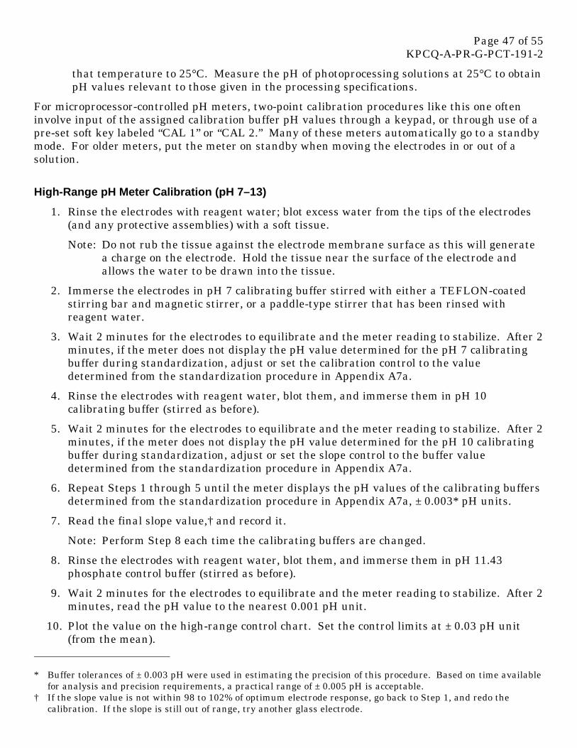
Page 47 of 55 KPCQ-A-PR-G-PCT-191-2
that temperature to 25°C. Measure the pH of photoprocessing solutions at 25°C to obtain pH values relevant to those given in the processing specifications.
For microprocessor-controlled pH meters, two-point calibration procedures like this one often involve input of the assigned calibration buffer pH values through a keypad, or through use of a pre-set soft key labeled “CAL 1” or “CAL 2.” Many of these meters automatically go to a standby mode. For older meters, put the meter on standby when moving the electrodes in or out of a solution.
High-Range pH Meter Calibration (pH 7–13)
1. Rinse the electrodes with reagent water; blot excess water from the tips of the electrodes (and any protective assemblies) with a soft tissue.
Note: Do not rub the tissue against the electrode membrane surface as this will generate a charge on the electrode. Hold the tissue near the surface of the electrode and allows the water to be drawn into the tissue.
2. Immerse the electrodes in pH 7 calibrating buffer stirred with either a TEFLON-coated stirring bar and magnetic stirrer, or a paddle-type stirrer that has been rinsed with reagent water.
3. Wait 2 minutes for the electrodes to equilibrate and the meter reading to stabilize. After 2 minutes, if the meter does not display the pH value determined for the pH 7 calibrating buffer during standardization, adjust or set the calibration control to the value determined from the standardization procedure in Appendix A7a.
4. Rinse the electrodes with reagent water, blot them, and immerse them in pH 10 calibrating buffer (stirred as before).
5. Wait 2 minutes for the electrodes to equilibrate and the meter reading to stabilize. After 2 minutes, if the meter does not display the pH value determined for the pH 10 calibrating buffer during standardization, adjust or set the slope control to the buffer value determined from the standardization procedure in Appendix A7a.
6. Repeat Steps 1 through 5 until the meter displays the pH values of the calibrating buffers determined from the standardization procedure in Appendix A7a, ± 0.003* pH units.
7. Read the final slope value,† and record it.
Note: Perform Step 8 each time the calibrating buffers are changed.
8. Rinse the electrodes with reagent water, blot them, and immerse them in pH 11.43 phosphate control buffer (stirred as before).
9. Wait 2 minutes for the electrodes to equilibrate and the meter reading to stabilize. After 2 minutes, read the pH value to the nearest 0.001 pH unit.
10. Plot the value on the high-range control chart. Set the control limits at ± 0.03 pH unit (from the mean).
* Buffer tolerances of ± 0.003 pH were used in estimating the precision of this procedure. Based on time available for analysis and precision requirements, a practical range of ± 0.005 pH is acceptable.
† If the slope value is not within 98 to 102% of optimum electrode response, go back to Step 1, and redo the calibration. If the slope is still out of range, try another glass electrode.

Page 48 of 55 KPCQ-A-PR-G-PCT-191-2
Low-Range pH Meter Calibration (pH 2–7)
1. Rinse the electrodes with reagent water; blot excess water from the tips of the electrodes (and any protective assemblies) with a soft tissue.
Note: Do not rub the tissue against the electrode membrane surface as this will generate a charge on the electrode. Hold the tissue near the surface of the electrode and allow the water to be drawn into the tissue.
2. Immerse the electrodes in pH 7 calibrating buffer stirred with either a TEFLON-coated stirring bar and magnetic stirrer, or a paddle-type stirrer that has been rinsed with reagent water.
3. Wait 2 minutes for the electrodes to equilibrate and the meter reading to stabilize. After 2 minutes, if the meter does not display the pH value determined for the pH 7 calibrating buffer during standardization, adjust or set the calibration control to the value determined from the standardization procedure in Appendix A7a.
4. Rinse the electrodes with reagent water, blot the excess water, and immerse the electrodes in pH 4 calibrating buffer (stirred as before).
5. Wait 2 minutes for the electrodes to equilibrate and the meter reading to stabilize. After 2 minutes, if the meter does not display the pH value determined for the pH 4 calibrating buffer during standardization, adjust the calibration control until it does (or set the meter to the value determined from the standardization procedure in Appendix A7a).
6. Repeat Steps 1 through 5 until the meter displays the pH values of the calibrating buffers determined from the standardization procedure in Appendix A7a, ± 0.003* pH units.
7. Read the final slope value,† and record it.
8. Rinse the electrodes with reagent water, blot them, and immerse them in pH 3.63 tartrate low pH control buffer (stirred as before).
Note: Perform Step 8 each time the calibrating buffers are changed.
9. Wait 2 minutes for the electrodes to equilibrate and the meter reading to stabilize. After 2 minutes, read the pH value to the nearest 0.001 pH unit.
10. Plot the value on the low-range control chart. Set the control limits at ± 0.020 pH units (from the mean).
Note: The low pH tartrate control buffer is more stable than the high pH phosphate control buffer, allowing tighter limits to be maintained.
SAMPLE PREPARATION
No sample preparation is required other than temperature equilibration to 25°C. A sample size of 80 to 120 mL is adequate. You can use an 8-ounce (approximately 250-mL) wide-mouth jar as
* Buffer tolerances of ± 0.003 pH were used in estimating the precision of this procedure. Based on time available for analysis and precision requirements, a practical range of ± 0.005 pH is acceptable.
† If the slope value is not within 98 to 102% of optimum electrode response, go back to Step 1, and redo the calibration. If the slope is still out of range, try another glass electrode.
Page 49 of 55 KPCQ-A-PR-G-PCT-191-2
a sample container. This allows you to cap the sample and provides adequate space for the electrode pair and stirring apparatus.
MEASURING pH
After calibration of the meter for the required pH range and temperature equilibration of the sample, determine the sample pH as follows.
1. Verify that the sample temperature is 25 ± 0.25°C.
2. Rinse the electrodes with reagent water, blot them, and immerse them in the sample with stirring.
3. Wait 2 minutes for the electrodes to equilibrate and the meter reading to stabilize.
4. Read the pH value to 0.001 pH unit and record it to the nearest 0.01 pH unit.
5. Recalibrate the meter between sample measurements if possible.
Note: If you must measure several samples of similar pH before recalibration, we rec-ommend a maximum of three measurements to maintain precision. Measuring a larger number of seasoned samples without recalibration increases the variability of the system, and may lead to difficulty in keeping buffer values within the specified tolerances. If you measure samples of widely differing pH (i.e., 7.5 and 12), you must recalibrate between samples in most cases.
If you are measuring more than one sample, always calibrate the meter after the final sample to ensure that no malfunction occurred during the process. If the specified buffer tolerances cannot be met, you must remeasure the samples run since the last calibration.
CALCULATIONS
Plot the pH values of the phosphate and tartrate control buffers for each meter in the lab during meter standardization. Calculate and plot the moving range for each buffer. In addition to providing information on the current status of your pH measurement system, this enables systems in other laboratories that are capable of maintaining control on these buffers to obtain similar mean pH values on the same photoprocessing solutions.
REPORTING RESULTS
Report the sample pH value to the nearest 0.01 pH unit, and state the measurement temperature (25°C).
APPENDICES
A7a Standardization of Calibrating Buffer Solutions
A7b Electrode Care
A7c Approved Packaged Buffers

Page 50 of 55 KPCQ-A-PR-G-PCT-191-2
Appendix A7a Standardization of Calibrating Buffer Solutions
Note: The pH values of the reference buffers cited below are taken from the Certificate of Analysis that accompanies each lot of standard reference material. When you purchase a new lot, use the value on the new certificate.
HIGH-RANGE pH METER CALIBRATION
1. Bring samples of the pH 7.00 and 9.18 reference buffers and the pH 7 and 10 calibrating buffers to be standardized to 25°C.
2. Rinse the electrodes with reagent water, blot them, and immerse them in pH 7.00 reference buffer (stirred as before).
3. Wait 2 minutes for the electrodes to equilibrate and the meter reading to stabilize. After 2 minutes, if the meter does not read pH 6.863,* adjust the calibration control (or set the meter) to 6.8.63.
4. Rinse the electrodes with reagent water, blot them, and immerse them in pH 9.18 reference buffer (stirred as before).
5. Wait 2 minutes for the electrodes to equilibrate and the meter reading to stabilize. After 2 minutes, if the meter does not read pH 9.180,* adjust the slope control (or set the meter) to 9.180.
6. Repeat Steps 1 through 5 until the meter reads the reference buffer values ± 0.003 pH units.
7. Read the final slope value,† and record it.
STANDARDIZATION OF HIGH-RANGE CALIBRATING BUFFERS
1. Using the just-calibrated meter and the “Measuring pH” procedure on page 5, measure the pH 7 calibrating buffer; record the pH.
2. Recalibrate the meter with reference buffers, and remeasure the pH 7 calibrating buffer; record the pH.
3. Use the average of the two pH measurements.
4. Recalibrate the meter with reference buffers, and measure the pH 10 calibrating buffer; record the pH.
5. Recalibrate the meter, and remeasure the pH 10 calibrating buffer; record the pH.
6. Use the average of the two pH measurements.
* These pH values are from the Certificates of Analysis for each current lot of NIST SRM buffer material. The values are likely to change slightly when you purchase a new lot of SRM. Use the new values when you begin to use the new lot of material.
† If the slope value is not within 98 to 102% of maximum electrode response, go back to Step 1 (meter calibration), and redo the calibration. If the slope is still out of range, try another glass electrode.

Page 51 of 55 KPCQ-A-PR-G-PCT-191-2
7. Repeat this procedure once a week.*
LOW-RANGE pH METER CALIBRATION
1. Bring the pH 7.00 and 4.01 reference buffers and the pH 4.01 calibrating buffer to be standardized to equilibrium at 25°C.
2. Rinse the electrodes with reagent water, blot them, and immerse them in pH 7.00 reference buffer (stirred as before).
3. Wait 2 minutes for the electrodes to equilibrate and meter reading to stabilize. After 2 minutes, if the meter does not read pH 6.863,† adjust the calibration control (or set the meter) to 6.863.
4. Rinse the electrodes with reagent water, blot them, and immerse them in pH 4.01 reference buffer (stirred as before).
5. Wait 2 minutes for electrodes to equilibrate and meter reading to stabilize. After 2 minutes, if the meter does not display pH 4.006,† adjust the slope control (or set the meter) to 4.006.
6. Repeat Steps 1 through 5 until the meter reads the reference buffer values ± 0.003 pH units.
7. Read the final slope value,‡ and record it.
STANDARDIZATION OF LOW-RANGE CALIBRATING BUFFER
1. Using the just-calibrated meter and the “Measuring pH” procedure on page 5, measure the pH calibrating buffer; record the pH.
2. Recalibrate the meter with reference buffers, and remeasure the pH 4 calibrating buffer; record the pH.
3. Use the average of the two pH measurements.
4. Repeat this procedure once a week.*
* Our experience has shown the commercially-available calibrating buffers listed in A7c are stable for up to two months under Rochester laboratory conditions and do not need to be standardized each week. Adequate precautions have been taken by the vendors to protect against biological growth (biocides), aerial oxidation (self-collapsible polyethylene cubes), and light effects (cubes contained in cardboard boxes during use). This may not be true of other vendor’s commercially-prepared buffers, and they may still require weekly standardization. When standardizing the calibrating buffers less than once per week, use the average of three pH measurements instead of two. It is essential that the controls be run as recommended in this procedure when the calibrating buffers are standardized less than once per week, so that any changes in the calibrating buffers can be detected. Please read Appendix A2.5.
† These pH values are from the Certificates of Analysis for each current lot of NIST SRM buffer material. The values are likely to change slightly when you purchase a new lot of SRM. Use the new values when you begin to use the new lot of material.
‡ If the slope value is not within 98 to 102% of maximum electrode response, go back to Step 1 (meter calibration), and redo the calibration. If the slope is still out of range, try another glass electrode.

Page 52 of 55 KPCQ-A-PR-G-PCT-191-2
Appendix A7b Electrode Care
Follow the manufacturers’ recommendations for electrode care when possible. There is much conflicting information on suitable storage solutions for glass electrodes. We recommend using pH 7 equimolar phosphate buffer for glass-electrode storage, and 3.5 M potassium chloride buffer for reference electrode storage when the electrode pair is out of service. For temporary storage of the electrode pair between measurements, use the pH 7 storage buffer (0.1 M potassium chloride in pH 7 equimolar phosphate buffer).
pH Electrodes — Preconditioning/Rejuvenation
Follow the manufacturer’s recommendations for preconditioning glass pH electrodes. A minimum soaking time of 2 hours in pH 7 equimolar phosphate buffer is recommended before use for pH measurement; overnight soaking is better.
Take the following rejuvenating steps if an electrode fails to meet the slope criterion, cannot achieve the assigned buffer values, or gives an unsatisfactory value when you measure the control buffer.
1. Detach the electrode leads from the meter.
2. Place the glass electrode tip in 1.0 N hydrochloric acid for 5 minutes, followed by 5 minutes in 1.0 N sodium hydroxide. Return the electrode to 1.0 N hydrochloric acid for an additional 5 minutes. Rinse the electrode with reagent water.
3. Soak in pH 7 buffer for 2 hours.
4. Reconnect the electrode and try another calibration. If there is no improvement, discard the electrode.
Note: More severe reconditioning procedures are not recommended due to both the toxicity of reagents required and the cost in analyst time versus the cost of electrode replacement.
5. If there is an improvement, but the electrode is still not reading the required values, repeat the sodium or potassium hydroxide and hydrochloric acid soaks, and try another calibration. If there is no improvement, discard the electrode.
Reference Electrode — Care/Rejuvenation
Calomel Reference Electrodes
Before putting a new calomel reference electrode into service, withdraw the saturated potassium chloride filling solution and refill with 3.5 M potassium chloride solution. The lower salt concentration produces less crystallization inside the electrodes and in the reference junction.
At the beginning of each shift or day, withdraw the potassium chloride filling solution and refill the electrode with fresh 3.5 M potassium chloride solution.

Page 53 of 55 KPCQ-A-PR-G-PCT-191-2
Silver/Silver Chloride Electrodes
Before putting a new silver/silver chloride reference electrode into service, withdraw the saturated potassium chloride filling solution and refill with 3.5 M potassium chloride solution saturated with silver chloride (the potassium chloride filling solution must be saturated with silver chloride, otherwise the internal silver chloride element will begin to dissolve).
At the beginning of each shift or day, withdraw the potassium chloride filling solution and refill the electrode with fresh 3.5 M potassium chloride solution saturated with silver chloride.
When poor performance of the pH measurement system does not improve after you substitute a new pH electrode, reference-electrode junction clogging may be the problem, especially where inaccurate or unsteady readings are obtained. If the filling solution becomes contaminated, refill with fresh solution and recheck the system. Check frit-type junctions for flow by pressing just the tip of the reference electrode gently against a paper towel several times. A small wet spot will be visible if the junction is flowing.
Clear a clogged calomel reference electrode by soaking the electrode junction for 1/2 hour in a warm (not above 50°C) solution of 3.5 M potassium chloride diluted 1:9 with distilled water. Drain the electrolyte and replace with fresh 3.5 M potassium chloride solution, and retest the electrode.
For clogged silver/silver chloride reference electrodes, a 10-minute soak in 10% ammonium hydroxide solution can remove precipitated silver chloride from the junction. The electrode must contain filling solution during this procedure. Avoid higher concentrations of ammonium hydroxide solution or longer periods of soaking, because you may begin to damage the reference element in some types of silver/silver chloride reference electrodes.
As with glass electrodes, more severe rejuvenation procedures are not recommended because they are costly, and in many cases, do more to damage the electrode than to improve its performance.
Combination Electrodes
Follow the manufacturer’s recommendations for care and rejuvenation of combination electrodes.
Reference-Electrode Accuracy Check
Assess errors of liquid-junction potential in reference electrodes by measuring the pH of the pH 7 equimolar phosphate buffer at two ionic strengths differing by a factor of 10.
1. Standardize the meter with pH 7.00 reference buffer and pH 4.01 reference buffer as in “Low-Range pH Meter Calibration.”
2. Dilute 110 mL of the pH 7 calibrating buffer to 1 litre with reagent water.
3. Measure the pH of the diluted buffer. The meter reading should be 7.065 ± 0.010 pH units for a properly functioning electrode reference junction.

Page 54 of 55 KPCQ-A-PR-G-PCT-191-2
Appendix A7c Approved Packaged Buffers
NIST Reference Buffers
• pH 4.01, 500 mL, Radiometer America CAT No. 943111.
• pH 6.84, 500 mL, Radiometer America CAT No. 943112.
• pH 9.18, 500 mL, Radiometer America CAT No. 943113.
Manufactured by and available from:
Radiometer America, Inc. 811 Sharon Drive Westlake, OH 44145 (800) 736-0600
For those wishing to mix reference buffers from standard materials, they are available from the National Institute of Standards and Technology. To produce NIST quality buffer solutions, you must follow exactly the mixing instructions provided with the materials.
NIST Standard Reference Materials (SRM’s) ordering address:
Office of Standard Reference Materials Room 205, Building 202 National Institute of Standards and Technology Gaithersburg, MD 20899 (301) 975-6776
• Potassium Hydrogen Phthalate, KHC8H4O4 NIST Ion Activity/pH Standard SRM-185f (or subsequent lot of SRM-185)
• Potassium Dihydrogen Phosphate, KH2PO4 NIST Ion Activity/pH Standard SRM-186Id (or subsequent lot of SRM-186I)
• Sodium Monohydrogen Phosphate, Na2HPO4 NIST Ion Activity/pH Standard SRM-186Iid (or subsequent lot of SRM-186II)
• Sodium Tetraborate Decahydrate, Na2B4O7 • 10 H2O NIST Ion Activity/pH Standard SRM-187c (or subsequent lot of SRM-187)
Calibrating Buffers
• pH 4, 20 L, VWR CAT No. 34180-639 or equivalent.
• pH 7, 20 L, VWR CAT No. 34180-661 or equivalent.
• pH 10, 20 L, Fisher CAT No. SB-115-20.
The pH 4 and 7 buffers are available from VWR Scientific Inc. VWR has offices throughout the world, consult your local directory for the address and phone number nearest you.
The pH 10 buffer available from Fisher Scientific Company has better stability than the pH buffer of other manufacturers. Substitutions are not recommended.

Page 55 of 55 KPCQ-A-PR-G-PCT-191-2
Fisher Scientific Company 711 Forbes Avenue Pittsburgh, PA 15219 (412) 562-1394 / (412) 562-8300
Control Buffers
• pH 3.63, SPI CAT No. 1750
• pH 11.43, SPI CAT No. 6805
Manufactured by and available from:
Solutions Plus Inc. 23 Cassens Court Fenton, MO 63026 (314) 349-4922

Page 1 of 2 KPCQ-A-PR-G-PCT-191-2 TR Acc. #