
pH CONTROLLER/MONITOR - sunwe.com.t · pH CONTROLLER/MONITOR Model : PPH-2108 Your purchase of this...
23
pH CONTROLLER/MONITOR Model : PPH-2108 Your purchase of this pH CONTROLLER/MONITOR MONITOR marks a step forward for you into the field of precision measurement. Although this pH controller is a complex and delicate instrument, its durable structure developed. Please read the following instructions carefully and always keep this manual within easy reach. OPERATION MANUAL
Transcript of pH CONTROLLER/MONITOR - sunwe.com.t · pH CONTROLLER/MONITOR Model : PPH-2108 Your purchase of this...

pHCONTROLLER/MONITORModel : PPH-2108
Your purchase of this pH CONTROLLER/MONITORMONITOR marks a step forward for you into the field ofprecision measurement. Although this pH controller is acomplex and delicate instrument, its durable structuredeveloped. Please read the following instructions carefullyand always keep this manual within easy reach.
OPERATION MANUAL

Caution Symbol
Caution :
* Risk of electric shock !
Caution :* Do not use fingers or any tool
to touch the FLASH TUBE.* The instrument contains no user
serviceable parts and should notbe opened by the user.
* Repair or after service should bedone by a qualified technicianonly.
* Power plug should apply the correctACV power voltage
* Operating duty cycle should beadhered to.
* Cleaning - Only use the dry cloth to clean the plastic case !
* Equipment protectted throughoutby Double Insulation or ReinforcedInsulation.
Environmental Condition
* Comply with EN61010.Transient overvoltage at Mains Supply 2500V.
* Pollution Degree 2.* Altitude up to 2000 meters.* Indoor use.* Relative humidity 80% max.

TABLE OF CONTENTS
1. FEATURES.......................................................................12. SPECIFICATIONS.............................................................2 2-1 General Specifications................................................ 2
2-2 Electrical Specifications...............................................43. FRONT PANEL DESCRIPTION............................................5
3-1 Display......................................................................53-2 PV ( process value ) indicator..................................... 53-3 SV ( set value ) indicator............................................ 53-4 Set Button.................................................................53-5 Button..................................................................▼ 53-6 Button..................................................................▲ 53-7 PH/Temp Button........................................................ 53-8 pH control relay indicator............................................53-9 Temp. control relay indicator...................................... 53-10 pH indicator.............................................................53-11 Temp. indicator........................................................53-12 Wire terminals ........................................................ 53-13 RS232 terminal........................................................ 53-14 BNC Input socket .................................................... 53-15 Case holder ............................................................ 53-16 pH Electrode plug ( optional )................................... 53-17 pH Electrode ( optional )...........................................53-18 Temp. Probe ( optional )...........................................53-19 Temp. Wires ( optional )...........................................5
4. MEASURING PROCEDURE.................................................54-1 Terminal connection...................................................64-2 pH calibration ........................................................... 64-3 pH measurement ( with ATC probe )........................... 74-4 pH measurement ( without ATC probe )...................... 74-5 1st layer setting procedures........................................84-6 2nd layer setting procedures.......................................10
5. pH CALIBRATION PROCEDURES....................................... 146. RS232 PC SERIAL INTERFACE.......................................... 177. pH ELECTRODE QUALITY CHECK......................................198. SYSTEM RESET............................................................... 199. THE ADDRESS OF AFTER SERVICE CENTER...................... 20

1. FEATURES
* Professional pH and Temp. measurement monitor and controller.
* pH range : 0 to 14 pH x 0.01 pH.* pH function with high input impedance avoids measuring
error.* Optional Temp. probe ( ATC probe, Automatic Temp.
Compensation probe ) is available for pH measurementcompensation and the Temp. measurement.
* Wide manual temperature compensation for pH function, adjustment can be easily operated by push button onthe front panel.
* pH calibration is easily to be done by push button on thefront panel.
* Build in pH control relay and the Temp. control relay.* Relay will be make action ( On/Off ) when the reading
value reach high limit or low limit value.* Temperature Offset value setting.* Hysteresis value setting for high and low alarm.* , temp. unit setting with default.℃ ℉* Large red LED display, high brightness and easy to read.* RS232 computer interface, send out the pH and the
temperature data at the same time.* Optional pH electrode.* Optional Temperature probe ( ATC probe ).* Optional data acquisition software.* Optional GSM controller.* Microprocessor circuit ensures high accuracy and
provides special functions and features.* Standard 96 X 48 mm DIN case.* Wide applications: water conditioning, aquariums,
beverage, fish hatcheries, food processing,photography, laboratory, paper industry, platingindustry, quality control, school & college.
1

2. SPECIFICATIONS
2-1 General Specifications
Display 4 digits red LED, digit size : 14 mm.Circuit Custom chip of microprocessor LSI
circuit.Range PH 0 to 14 PH
Temp. -30 to 100 ℃Display Unit pH pH
Temp. , ℃ ℉
pH Input 10^12 ohmImpedanceTemperature Manual -30 to 100 , be adjusted by℃
Compensation push button on front panel.for pH Automatic With the optional Temp.measurement ( ATC ) probe ( TP-07A )
0 to 65 .℃
pH PH7, PH4, and PH10, 3 points calibration Calibration ensure the best linearity and accuracy.pH Optional,Electrode Any PH electrode with BNC connector.Temp. Probe Optional, 0 to 65 , TP-07A℃
ATC ProbeProbe Calibration Can set the meter's total operation period toPeriod Setting warn the user to make the new calibration for * PCPS function the pH electrode.Sampling Time Approx. 1 second.Relay outputs Number 2 relays
Function Relay 1 :pH control relay.Relay 2 :Temperature control relay.
Max load 1 ACA/250 ACV1 DCA/24 DCV
2
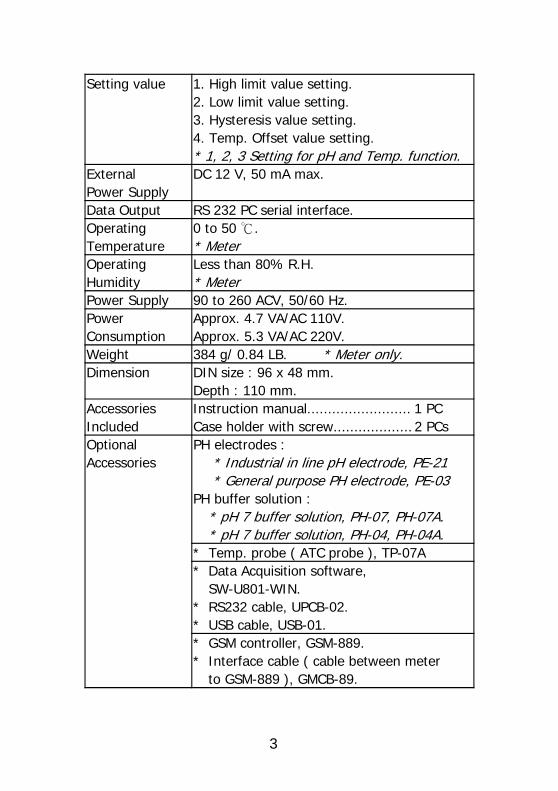
Setting value 1. High limit value setting.2. Low limit value setting.3. Hysteresis value setting.4. Temp. Offset value setting.* 1, 2, 3 Setting for pH and Temp. function.
External DC 12 V, 50 mA max.Power SupplyData Output RS 232 PC serial interface.Operating 0 to 50 .℃
Temperature * MeterOperating Less than 80% R.H.Humidity * MeterPower Supply 90 to 260 ACV, 50/60 Hz.Power Approx. 4.7 VA/AC 110V.Consumption Approx. 5.3 VA/AC 220V.Weight 384 g/ 0.84 LB. * Meter only.Dimension DIN size : 96 x 48 mm.
Depth : 110 mm.Accessories Instruction manual..........................1 PCIncluded Case holder with screw................... 2 PCsOptional PH electrodes :Accessories * Industrial in line pH electrode, PE-21
* General purpose PH electrode, PE-03PH buffer solution :
* pH 7 buffer solution, PH-07, PH-07A.* pH 7 buffer solution, PH-04, PH-04A.
* Temp. probe ( ATC probe ), TP-07A* Data Acquisition software,
SW-U801-WIN.* RS232 cable, UPCB-02.* USB cable, USB-01.* GSM controller, GSM-889.* Interface cable ( cable between meter
to GSM-889 ), GMCB-89.
3

2-2 Electrical Specifications (23 ± 5 )℃
pH ( meter only )
Range Resolution Accuracy0 to 14 PH 0.01 PH ± (0.02 PH + 2 d)
Temperature ( used optional Temp. probe, TP-07 A)
Measurement Range Resolution Accuracy℃ 0 to 65 ℃ ℃ 0 to 65 ℃ ℃ 0.8 .℃
℉ 32 to 149 ℉ ℉ 32 to 149 ℉ ℉ 1.5 .℉
* Specification tests under the environment RF Field Strength less than 3 V/M and frequency less than 30 MHz only.
4
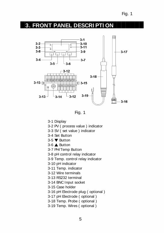
Fig. 1
3. FRONT PANEL DESCRIPTION
Fig. 1
3-1 Display3-2 PV ( process value ) indicator3-3 SV ( set value ) indicator3-4 Set Button3-5 Button▼
3-6 Button▲
3-7 PH/Temp Button3-8 pH control relay indicator3-9 Temp. control relay indicator3-10 pH indicator3-11 Temp. indicator3-12 Wire terminals3-13 RS232 terminal3-14 BNC Input socket 3-15 Case holder 3-16 pH Electrode plug ( optional )3-17 pH Electrode ( optional )3-18 Temp. Probe ( optional )3-19 Temp. Wires ( optional )
5

4. MEASURING PROCEDURE
Terminal layout Fig. 2
4-1 Terminal connection1)Input the ACV power ( 90 to 260 ACV ) to T1, T2.
Do not input theover voltage to the AC input terminals.
2)Connect the " pH Control Relay " output from T3, T4.Connect the " Temp. Control Relay " output from T5, T6.
4-2 pH calibration
When the first time use the pH electrode or the pH electrode already be used a long period, then beforethe measurement, it should make thecalibration first, the calibration procedures, refer topage
Chapter 5. pH CALIBRATION PROCEDURES
6

4-3 pH measurement ( with ATC probe )1)Prepare the optional Temp. probe ( ATC probe TP-07A )
connect the Temp. Wires ( 3-19, Fig. 1 ) to the " Wireterminals " ( 3-12 ) T10, T9 ( bare wire ).Prepare the optional pH electrode ( For example PE-21,PE-03... ), Connect the " pH Electrode plug " ( 3-16,Fig. 1 ) to " BNC Input socket " ( 3-14, Fig. 1 ).
2)Power on the meter, immerse the above pH electrodeand the Temp. probe into the measuring solution.The " Display " ( 3-1, Fig. 1 ) will show the pH value,in the same time the " pH indicator " ( 3-10, Fig. 1 )will light.
3)Press the " PH/Temp Button " ( 3-7, Fig. 1 ) once, the " Temp. indicator " ( 3-11, Fig. 1 ) will light, the" Display " ( 3-1, Fig. 1 ) will show the Temp. valuethat sensing from the Temp. probe ( ATC probeTP-07A ).
* Press the " " PH/Temp Button " ( 3-7, Fig. 1 ) once again, the " Display " will return the " pH value ", in thesame time the " pH indicator " ( 3-10, Fig. 1 ) will light again.
* The pH measurement value will be compensated automaticallyby the Temp. value that sensing from the Temp. probe ( ATC probe, TP-07A ).
* During the Temp. measurement, if intend to change the defaultTemp. unit from the to , refer to page 10.℃ ℉
4-4 pH measurement ( without ATC probe )1)Prepare the optional pH electrode ( For example PE-21,
PE-03... ), Connect the " pH Electrode plug " ( 3-16,Fig. 1 ) to " BNC Input socket " ( 3-14, Fig. 1 ).
Not connect the Temp. probe ( ATC probe , TP-07A ) to the " Wire terminals " ( 3-12 ) T10, T9.
7

2)Power on the meter, Immerse the above pH electrodeinto the measuring solution.The " Display " ( 3-1, Fig. 1 ) will show the pH value,in the same time the " pH indicator " ( 3-10, Fig. 1 )will light.
3)Press the " PH/Temp Button " ( 3-7, Fig. 1 ) once, the " Temp. indicator " ( 3-11, Fig. 1 ) will light, the " Display " ( 3-1, Fig. 1 ) will show the Manual Temp.value.
* Press the " " PH/Temp Button " ( 3-7, Fig. 1 ) once again, the " Display " will return the " pH value ", in thesame time the " pH indicator " ( 3-10, Fig. 1 ) will light again.
* The pH measurement value will be compensatedby the Manual Temp. value.
* The default " Manual Temp. value " is 25 .℃
* The procedures to set the Manual Temp. value, refer to page 11.
* The method to change the default Manual Temp. unit from the to , refer to page 10.℃ ℉
4-5 1st layer setting procedures
LoLt Low Limit HILt High Limit
Low Limit Value Setting
1)Press the " Set Button " ( 3-4, Fig. 1 ) once, the " Display " will show " LoLt ", now the meter is readyfor the pH " Low Limit " value setting.
Press the " " PH/Temp Button " ( 3-7, Fig. 1 ) once, the " Temp indicator " ( 3-11, Fig. 1 ) will light, nowthe meter is ready for the Temperature " Low Limit "value setting.
8

Remark :* Under " Display " show " LoLt ", if " pH indicator "
( 3-10, Fig. 1 ) is lit, meter is ready for " pH LowLimit " setting.
* Under " Display " show " LoLt ", if " Temp. indicator " ( 3-11, Fig. 1 ) is lit, meter is ready for " TemperatureLow Limit " value setting.
* The function of " Low Limit value " setting, refer to page 12, Fig. 2.
2)Use the " " Button " ( 3-5, Fig. 1 ) and the " ▼ ▲Button " ( 3-6, Fig. 1 ) to adjust the desiring " LowLimit " value.* When adjust the value, the " SV indicator " ( 3-3, Fig. 1 )
will light.
High Limit Value Setting
1)After set the " Low Limit " value, press the " SetButton " ( 3-4, Fig. 1 ) twice, the " Display " will show " HILt ", now the meter is ready for the pH " HighLimit " value setting.
Press the " " PH/Temp Button " ( 3-7, Fig. 1 ) once, the " Temp indicator " ( 3-11, Fig. 1 ) will light, nowthe meter is ready for the Temperature " High Limit "value setting.
Remark :* Under " Display " show " HILt ", if " pH indicator "
( 3-10, Fig. 1 ) is lit , meter is ready for " pH HighLimit value " setting.
* Under " Display " show " HILt ", if " Temp. indicator " ( 3-11, Fig. 1 ) is lit, it meter is ready for " Temperature High Limit value " setting.
* The function of " High Limit value " setting, refer to page 12, Fig. 2.
9

2)Use the " " Button " ( 3-5, Fig. 1 ) and the " ▼ ▲Button " ( 3-6, Fig. 1 ) to adjust the desiring " HighLimit " value.* When adjust the value, the " SV indicator " ( 3-3, Fig. 1 )
will light.
After adjust the " High Limit " value, press the " SetButton " ( 3-4, Fig. 1 ) twice, " Display " will return tothe normal measuring screen.
4-6 2nd layer setting procedures
tPty Temp. unit setting tPSt Temp. compensation
value setting HySt Hysteresis setting tPoA Temp. Offset setting PCPS Probe Calibration
Period Setting
Temperature unit setting
1)Press the " Set Button " ( 3-4, Fig. 1 ) continuously atleast two seconds, the " Display " will show " tPty ",now the meter is ready for the Temperature unit ( ,℃
) setting.℉2)Use the " " Button " ( 3-5, Fig. 1 ) and the " ▼ ▲
Button " ( 3-6, Fig. 1 ) to adjust the desiringtemperature unit to " C " or " F ".* When adjust the Temp. unit, the " SV indicator " ( 3-3, Fig. 1 )
will light.
10

Temp. compensation value setting
The pH measurement value is effected by themeasurement environment Temp. value. If intend tomake the precision pH measurement, it should connectthe Temp. probe ( ATC probe, TP-07A ) to " Wireterminals " T9, T10. Otherwise, it should adjust theTemp. compensation values to reach the Temp. valuesof the measured solution, the procedures are :
1)After select the temperature unit ( , ), press the℃ ℉" Set Button " ( 3-4, Fig. 1 ) twice, the " Display "will show tPSt ", now the meter is ready for thethe Temp. compensation value setting.
2)Use the " " Button " ( 3-5, Fig. 1 ) and the " ▼ ▲Button " ( 3-6, Fig. 1 ) to adjust the desiringTemp. compensation value.* If the meter already connect the Temp. probe ( ATC probe,
TP-07A ), though already adjust the Temp. compensationvalue, the pH measurement value will be not effected by thesetting Temp. compensation value, it compensated by the Temp. probe only.
* When adjust the Temp. compensation value, the " SV indicator " ( 3-3, Fig. 1 ) will light.
Hysteresis value setting
1)After select the temperature compensation value,press the " Set Button " ( 3-4, Fig. 1 ) twice, the " Display " will show HySt ", now the meter is readyfor the Hysteresis value setting.
2)Use the " " Button " ( 3-5, Fig. 1 ) and the " ▼ ▲Button " ( 3-6, Fig. 1 ) to adjust the desiringHysteresis setting value.* When adjust the Hysteresis value, the " SV indicator "
( 3-3, Fig. 1 ) and the " will light.
11

Press the " " PH/Temp Button " ( 3-7, Fig. 1 ) once, the " Temp indicator " ( 3-11, Fig. 1 ) will light, nowthe meter is ready for the Temperature " Hysteresis "value setting.
Remark :* Under " Display " show " HySt ", if " pH indicator "
( 3-10, Fig. 1 ) is lit, meter is ready for " pH Hysteresisvalue " setting.
* Under " Display " show " HySt ", if " Temp. indicator " ( 3-11, Fig. 1 ) is lit, meter is ready for " Hysteresis value " setting.
* The function of " Hysteresis value " setting, refer to page 12, Fig. 2.
Fig. 2
For example :
High limit value : 100Low limit value : 20Hysteresis value : 5
a. The control relay will On when measuring value up to 100.The control relay will Off again when measuring valuedown to 95.
b. The control relay will On when measuring value down to 20.The control relay will Off when measuring value up to 25.
Temp. offset value setting
1)After finish the Hysteresis setting, press the" Set Button " ( 3-4, Fig. 1 ) twice, the " Display "will show " tPoA ", now the meter is ready for thethe Temp. offset value setting.
2)Use the " " Button " ( 3-5, Fig. 1 ) and the " ▼ ▲Button " ( 3-6, Fig. 1 ) to adjust the desiringTemp. offset value.
12

* When adjust the Offset value, the " SV indicator " ( 3-3, Fig. 1 ) and Temp. indicator ( 3-11, Fig. 1 ) will light.
Remark :* For example of " Temp. Offset value setting " :
The Temp. reading value is 18.2The offset value is 1.1The new display value will be 19.3 ( 18.2 + 1.1).
Probe Calibration Period Setting ( PCPS )
Typically the pH electrode should be calibratedafter it is used for a certain period." Probe Calibration Period Setting function " can set aperiod time ( unit is hour, default value is 720 hours ), then after the pH electrode usage hours reach to settingPCPS hours, the display reading will present warningmessage to inform the user should to execute the newcalibration procedures.
1)After finish the Temp. offset value setting, press the" Set Button " ( 3-4, Fig. 1 ) twice, the " Display "will show " PCPS ", now the meter is ready for thethe PCPS value setting.
2)Use the " " Button " ( 3-5, Fig. 1 ) and the " ▼ ▲Button " ( 3-6, Fig. 1 ) to adjust the desiring " ProbeCalibration Period Setting value ( PCPS value ) ".
* When adjust the PCPS value, the " SV indicator " ( 3-3, Fig. 1 ) and pH indicator ( 3-10, Fig. 1 ) will light.
* When the meter's usage hours reach to the PCPS value, theDisplay will show text " CAL " and the measurement valuein alternation.
* It can reset the usage hours to zero by pressing the " Set Button " ( 3-4, Fig. 1 ) and the " Button " ▼
( 3-5, Fig. 1 ) at the same time.
13

Note : During the Display show above " CAL " text, before to reset the usage hours, the user can noexecute the normal function setting.
3)After finish the PCPS value setting, press the" Set Button " ( 3-4, Fig. 1 ) again, the " Display "will return to normal measurement screen and finish the " 2nd layer setting procedures ".
5. pH CALIBRATION PROCEDURES
5-1 Preparation and consideration of pH calibration1)Prepare the
a. " pH 7 buffer solution " ( optional, such as PH-07. PH-07A )b. " pH 4 buffer solution " ( optional, such as PH-04. PH-04A )
2)The complete calibration procedures should beexecuted by both buffer solution :a. " pH 7 buffer solution " b. " pH 4 buffer solution "
3)It should be calibrated under the " pH 7 buffersolution " at first, then calibrated under the " pH 4 buffer solution " following.
5-1 pH calibration ( without ATC probe )1)Power on the meter, immerse the pH electrode
into the standard " Buffer solution ".The " Display " ( 3-1, Fig. 1 ) will show the pH valueof the buffer solution.
2)Use the two fingers to press " Set Button " ( 3-4, Fig. 1 )and " Button " ( 3-6, Fig. 1 ) continuously at the▲same time until the " Display " show the text " CAL "/
Solution Temp. adjustment
Follow the text " CAL " , the display will show the existingmanual Temp. value with flashing, at the same time " SV indicator " ( 3-3, Fig. 1 ) and the " Temp. indicator "( 3-11 ) will light.
14

Use the " " Button " ( 3-5, Fig. 1 ) and the " ▼ ▲Button " ( 3-6, Fig. 1 ) to adjust the Display until itsvalue reach to the Temp. value of " Buffer solution ",then press " Set Button " ( 3-4, Fig. 1 ) will entry themanual Temp. value.
pH Calibration
After enter the above manual Temp. value, the Displaywill show the pH value 7.00 or 4.00 with flashing,
* Use the pH 7 buffer solution, it will show 7.00 * Use the pH 4 buffer solution, it will show 4.00
at the same time " SV indicator " ( 3-3, Fig. 1 ) andthe " pH indicator " ( 3-10 ) will light.
* If the aim calibration value is pH 7.00 ( 4.00 )exactly, then wait about 5 seconds the meter willentry the calibration value and finish the pHcalibration procedures , the Display will return tonormal screen, the " PV indicator " ( 3-2, Fig. 1 ) willon, the " SV indicator " ( 3-3, Fig. 1 ) will off.
* If the aim calibration value is not pH 7.00 ( 4.00 )exactly, during the Display flashing, use the " ▼Button " ( 3-5, Fig. 1 ) and the " Button " ( 3-6,▲Fig. 1 ) to adjust Display until it reach to thepH value of " Buffer solution ", then press " SetButton " ( 3-4, Fig. 1 ) to entry calibration data. TheDisplay will return to normal screen, the " PVindicator " ( 3-2, Fig. 1 ) will On, the " SV indicator "( 3-3, Fig. 1 ) will off.
During the calibration, if the Display show " Err ", means pH electrode's output value already beyond ± 1.2 pH and the electrode can not be used anymore, it should change the new electrode.
15

When change the new pH electrode, it recommendthat to execute the " SYSTEM RESET " at first,refer to page 19.
5-2 pH calibration ( with ATC probe )1)Power on the meter, immerse the above pH electrode
and the Temp. probe into the measuring solution.The " Display " ( 3-1, Fig. 1 ) will show the pH valueof the Buffer solution.
2)Use the two fingers to press " Set Button " ( 3-4, Fig. 1 )and " Button " ( 3-6, Fig. 1 ) continuously at the▲same time until the " Display " show the text " CAL ",then present the Temp. value with flashing thatsensing from the Temp. probe ( ATC probe ), afterfew seconds ( about 5 seconds ) the Display will changeto the pH value 7.00 or 4.00 with flashing,
* Use the pH 7 buffer solution, it will show 7.00 * Use the pH 4 buffer solution, it will show 4.00
at the same time " SV indicator " ( 3-3, Fig. 1 ) andthe " pH indicator " ( 3-10 ) will light.
* If the aim calibration value is pH 7.00 ( 4.00 )exactly, then wait about 5 seconds the meter willentry the calibration value and finish the pHcalibration procedures , the Display will return tonormal screen, the " PV indicator " ( 3-2, Fig. 1 ) willon, the " SV indicator " ( 3-3, Fig. 1 ) will off.
* If the aim calibration value is not pH 7.00 ( 4.00 )exactly, during the Display flashing, use the " ▼Button " ( 3-5, Fig. 1 ) and the " Button " ( 3-6,▲Fig. 1 ) to adjust Display until it reach to the pHvalue of " Buffer solution ", then press " Set Button " ( 3-4, Fig. 1 ) to entry calibration data. The Displaywill return to normal screen, the " PV indicator " ( 3-2, Fig. 1 ) will On, the " SV indicator " ( 3-3, Fig. 1 ) will off.
16

6. RS232 PC SERIAL INTERFACE
The instrument has RS232 PC serial interface via a 3.5mm terminal ( 3-13, Fig. 1 ).
The data output is a 16 digit stream which can beutilized for user's specific application.
A RS232 lead with the following connection will berequired to link the instrument with the PC serial port.
Meter PC(3.5 mm jack plug) (9W 'D" Connector)
Center Pin...............................Pin 4
Ground/shield........................ Pin 2
Pin 5
The 16 digits data stream will be displayed in thefollowing format :
D15 D14 D13 D12 D11 D10 D9 D8 D7 D6 D5 D4 D3 D2 D1 D0
17

Each digit indicates the following status :D15 Start WordD14 4D13 When send the upper display data = 1
When send the lower display data = 2D12 & D11 Annunciator for Display
= 01 ℃ = 02℉ pH = 05D10 Polarity
0 = Positive 1 = NegativeD9 Decimal Point(DP), position from right to the
left0 = No DP, 1= 1 DP, 2 = 2 DP, 3 = 3 DP
D8 to D1 Display reading, D8 = MSD, D1 = LSD.For example :
If the display reading is 1234, then D8 toD1 is : 00001234
D0 End Word
RS232 settingBaud rate 9600Parity No parityData bit no. 8 Data bitsStop bit 1 Stop bit
18

7. pH ELECTRODE QUALITY CHECK
If the pH electrode output value already beyond ± 1.2 pH, the electrode's quality is bad, it can not beused any more and should change the new electrode.
Install the pH electrode, power on the meter, use thetwo fingers to press both " Button " ( 3-5, Fig. 1 ) and▼" Button " ( 3-6, Fig. 1 ) Button continuously more▲than 2 seconds until the Display show the text " CHK " and flashing 6 times, then if Display show " oK " ,means the quality of the electrode is oK.if Display show " Err ", means the electrode is alreadyout of life and need to change the new electrode.
8. SYSTEM RESET
Power on the meter, use the two fingers to press " SetButton " ( 3-4, Fig. 1 ) and " PH/Temp. Button " ( 3-7,Fig. 1 ) continuously more than 5 seconds until theDisplay show the text " rSt ", release the buttons. After " rSt " text flashing 2 times will return to the normalscreen. The meter system will be reset, all thecalibration data will be cleared, the meter's internalfunction will return the default value.
190702-PPB2108

9. THE ADDRESS OF AFTER SERVICE CENTER
200704-PPB2108


