pH AND ORP NODE (NpH) - Lakewood Instruments€¦ · · 2015-12-30521 Series REF Varies 530...
26
LAKEWOOD INSTRUMENTS pH AND ORP NODE (NpH) INSTALLATION & OPERATION MANUAL SERIAL #:_______________ Lakewood Instruments 7838 North Faulkner Road, Milwaukee, Wisconsin 53224 USA Phone (800) 228-0839 • Fax (414) 355-3508 http://www.lakewoodinstruments.com
Transcript of pH AND ORP NODE (NpH) - Lakewood Instruments€¦ · · 2015-12-30521 Series REF Varies 530...

LAKEWOOD INSTRUMENTS
pH AND ORP NODE (NpH)
INSTALLATION & OPERATION MANUAL
SERIAL #:_______________
Lakewood Instruments 7838 North Faulkner Road, Milwaukee, Wisconsin 53224 USA Phone (800) 228-0839 • Fax (414) 355-3508 h t t p : / / w w w . l a k e w o o d i n s t r u m e n t s . c o m

pH and ORP Node (NPH) Instruction Manual 2

Lakewood Instruments
We thank you for your selection and purchase of a Lakewood Instruments product. With proper care and maintenance, this device should give you many years of trouble-free service. Please take the time to read and understand this Installation and Operation Manual, paying special attention to the sections on OPERATION and MAINTENANCE. If, in the future, any parts or repairs are required, we strongly recommend that only original replacement parts be used. Our Customer Service Department is happy to assist you with your parts or service requests.
Lakewood Instruments Customer Service and Technical Support Departments can be reached by calling (800) 228-0839 or faxing (414) 355-3508, Monday through Friday, 7:30 a.m. - 5:00 p.m. CST.
Mail should be sent to:
Lakewood Instruments
7838 North Faulkner Road Milwaukee, WI 53224 USA
pH and ORP Node (NPH) Instruction Manual 3

pH and ORP Node (NPH) Instruction Manual 4

pH AND ORP NODE (NPH)
Table of Contents INTRODUCTION 7 Introduction 7 Specifications 8 INSTALLATION 9 Checking 9 Connections 9 Service Light 9 Operation with 2000 Series Controllers (node installation) 10 CONFIGURATION 12 Configuration of Node with Sensors 12 Configuration of Node with Relays 14 MAINTENANCE AND TECHNICAL SERVICE 16 Technical Service 16 Troubleshooting 17 DRAWINGS 15
pH and ORP Node (NPH) Instruction Manual 5

pH and ORP Node (NPH) Instruction Manual 6

INTRODUCTION NPH The Model NPH pH and ORP Node is a LONWORKS®-compatible node that uses twisted pair communications. The NPH works with several different temperature compensation inputs and with pH or ORP sensors. These multiple-sensor input options allow for various sensors to be used. Temperature compensation is adjustable by pH per Celsius for use with various processes. Up to four NpH nodes may be installed on the 2000 series controller.
NOTE: To use the NpH with a 2000 series controller it must have the NIN option and contain Rel 98 Firmware. All controllers shipped after 1 June 98 will have Rel 98 firmware.
Relay configuration and datalogging After a NpH is installed, not only will you be able to view additional inputs you will also be able to datalog information and control relays based on the external device. LONWORKS is a registered trademark of Echelon Corporation.
pH and ORP Node (NPH) Instruction Manual 7

Specifications Sensor Connections BNC Sensor BNC Pin 1 none Pin 2 none Pin 3 Reference Pin 4 none Pin 5 Solution Ground and Temperature Compensator Pin 6 Temperature Compensator Range pH Range 0-14 (with proper pH sensor) ORP Range -2000 to +2000 (with proper ORP sensor) Temperature Compensation Inputs None 100 PTC
500 NTC 1K PTC 4K NTC 3K PTC 10K NTC 10K PTC
Compensation is adjustable by pH per °C (pH only) Power 24 VDC
Network and Power connections Service Light Service Pin
pH and ORP Node (NPH) Instruction Manual 8
INSTALLATION Checking
Inspect the shipping carton for obvious external damage. Note on the carrier's bill-of-lading the extent of the damage, if any, and notify the carrier. Save the shipping carton until your Node is started up.
If shipping damage has occurred, call the Lakewood Instruments Customer Service Department at (800) 228-0839 and return the controller to the factory in the original carton.
Connections
The NIN option is required on the 2000 series controller for the NPH to operate. The NIN option provides power and two way communications to the NPH. Refer to the drawings in the back of this manual for wiring details.
Service Light
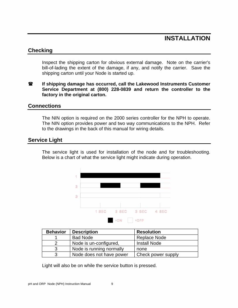
The service light is used for installation of the node and for troubleshooting. Below is a chart of what the service light might indicate during operation.
Behavior Description Resolution 1 Bad Node Replace Node 2 Node is un-configured, Install Node 3 Node is running normally none 3 Node does not have power Check power supply
Light will also be on while the service button is pressed.
pH and ORP Node (NPH) Instruction Manual 9

Operation with 2000 Series Controllers
Before it can be used, the NPH must be installed into the software of the controller. Under the Main Menu,
MAIN MENU =============
3 FEED SCHEDULE 4 ALARMS 5 WATER METERS 6 4-20 MA OUTPUTS 7 SYSTEM SETUP 8 CLOCK
highlight SYSTEM SETUP, then press ENT. You should see the following screen:
SYSTEM SETUP =================
1 PROCESS PARAMETERS 2 INITIALIZATION 3 DIGITAL INPUTS 4 FIRMWARE VERSIONS 5 SECURITY 6 DIAGNOSTICS 7 COMMUNICATIONS 8 NODE INSTALLATION
Highlight NODE INSTALLATION, then press ENT. You should see the following screen:
NODE INSTALLATION =====================
1 INSTALL A NEW NODE 2 DE-INSTALL A NODE
pH and ORP Node (NPH) Instruction Manual 10

Highlight INSTALL A NEW NODE, then press ENT. You should see the following screen:
INSTALL A NEW NODE =================
1 RELAYS 5-8 2 RELAYS 9-12 3 MAKEUP COND 4 REMOTE SENSOR 5 REMOTE SENSOR 6 REMOTE SENSOR 7 REMOTE SENSOR 8 ANOLOG INPUTS (4) 9 ANOLOG INPUTS (4) 10 DIGITAL INPUTS (4) 11 DIGITAL INPUTS (4)
NOTE: YOU MUST ASSIGN YOUR NPH TO REMOTE SENSOR. THEN YOU MAY SELECT PH OR ORP (DEPENDING ON SENSOR BEING USED). Select which node to install.
WHICH PROCESS? =============================
1 CONDUCTIVITY 2 pH 3 ORP
The following screen should appear:
PRESS SERVICE PIN
PRESS ANY KEY
Momentarily press the Service Pin on the node to be installed. The Service Light should turn on while the Service Pin is pressed. After the Service pin is released press any key on the key pad and the node will be installed.
pH and ORP Node (NPH) Instruction Manual 11

CONFIGURATION Configuration of Node with Sensors
For the NPH to work properly with different sensors it must be configured properly. Under the Main Menu,
MAIN MENU =============
3 BIO SCHEDULE 4 ALARMS 5 WATER METERS 6 4-20 MA OUTPUTS 7 SYSTEM SETUP 8 CLOCK
highlight SYSTEM SETUP, then press ENT. You should see the following screen:
SYSTEM SETUP =================
1 PROCESS PARAMETERS 2 INITIALIZATION 3 DIGITAL INPUTS 4 FIRMWARE VERSIONS 5 SECURITY 6 DIAGNOSTICS 7 COMMUNICATIONS 8 NODE INSTALLATION
Highlight PROCESS PARAMETERS, then press ENT. You should see the following screen (screen will vary depending on which other nodes are installed):
WHICH PROCESS
================= 1 pH 2 COND 3 pH-1
Select which node to set up. pH and COND are not nodes. Highlight the appropriate node and press ENT. You should see the following screen:
pH and ORP Node (NPH) Instruction Manual 12

pH-1
================= 1 CHANGE MY NAME 2 TEMP COMPENSATION 3 pH PER °C 4 SENSOR SHEILD 5 DAMPING
See the Sensor Configuration Chart to configure selections 2-5 above.
Sensor Sensor Shield Temp Comp.1167153 and 1167154
GND NONE
1167155 REF NONE 1169065 REF NONE 520 Series GND 10K PTC 521 Series REF Varies 530 Series GND 10K PTC
If you are not familiar with Damping or Percent/°C the values should be left at .5 sec for damping and 0.00 pH for pH per °C. All other pH and ORP sensors not manufactured by Lakewood Instruments will use REF for SENSOR SHIELD. Temperature input will vary by manufacturer.
pH and ORP Node (NPH) Instruction Manual 13

Configuration of Node with Relays The N420I can be used to control relays in the 2000 series controller or the NRLY node. Under the Main Menu,
MAIN MENU =============
1 PROCESS 2 RELAYS 3 BIO SCHEDULE 4 ALARMS 5 WATER METERS 6 4-20 MA OUTPUTS 7 SYSTEM SETUP 8 CLOCK
highlight RELAYS, then press ENT. You should see the following screen:
WHICH RELAY? ==============================
= 1 BLOW 2 RLY2 3 RLY3 4 RLY4
Highlight the appropriate relay , then press ENT. You should see the following screen:
RLY2 ==============================
= 1 DISABLE 2 SETPOINT 3 WATER METER 4 PERCENT BLOWDOWN 5 PERCENT OF TIME 6 FEED SCHEDULE
Highlight SETPOINT , then press ENT. You should see the following screen:
pH and ORP Node (NPH) Instruction Manual 14
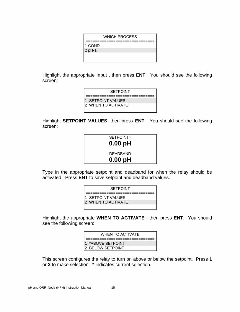
WHICH PROCESS
============================== 1 COND 2 pH-1
Highlight the appropriate Input , then press ENT. You should see the following screen:
SETPOINT
============================== 1 SETPOINT VALUES 2 WHEN TO ACTIVATE
Highlight SETPOINT VALUES, then press ENT. You should see the following screen:
SETPOINT=
0.00 pH
DEADBAND
0.00 pH
Type in the appropriate setpoint and deadband for when the relay should be activated. Press ENT to save setpoint and deadband values.
SETPOINT
============================== 1 SETPOINT VALUES 2 WHEN TO ACTIVATE
Highlight the appropriate WHEN TO ACTIVATE , then press ENT. You should see the following screen:
WHEN TO ACTIVATE ============================== 1 *ABOVE SETPOINT 2 BELOW SETPOINT
This screen configures the relay to turn on above or below the setpoint. Press 1 or 2 to make selection. * indicates current selection.
pH and ORP Node (NPH) Instruction Manual 15

Maintenance and Technical Service Technical Service
Technical Support for Lakewood Instruments can be reached by calling (800) 228-0839 or faxing (414) 355-3508, Monday through Friday, 7:30 a.m. – 5.00 p.m. CST.
NOTE: IF YOU CALL FOR TROUBLESHOOTING HELP, PLEASE HAVE THE MODEL NUMBER, SERIAL NUMBER, AND ANY OPTIONS PERTAINING TO YOUR UNIT AVAILABLE FOR REFERENCE.
Mail and returns should be sent to:
Lakewood Instruments 7838 North Faulkner Road Milwaukee, WI 53224 USA
When any merchandise is to be returned to the factory, please call and obtain a Return Goods Authorization (RGA) number and have the following information available: • Customer’s name, address, telephone and fax numbers (shipping and billing). • A hard copy purchase order number for cases where repairs or parts are
required that are not under warranty. • A contact person’s name and telephone number to call if the equipment is
beyond repair or to discuss any other warranty matter. • Equipment model and serial numbers. • Reason for return, e.g., repair, warranty, incorrect part, etc. We will then fax to your attention an RGA form that must accompany the returned item. NOTE: THE RGA NUMBER MUST BE CLEARLY WRITTEN ON THE OUTSIDE OF THE PACKAGE(S) BEING RETURNED.
ANY ITEMS SENT BACK TO THE FACTORY WITHOUT AN RGA NUMBER WILL BE REFUSED
AND RETURNED TO SENDER
pH and ORP Node (NPH) Instruction Manual 16

Troubleshooting PROBLEM WHAT THIS MEANS CORRECTIVE ACTION Screen Displays "pH-1: LOW ALARM"
The pH input is below the low alarm setting.
Refer to Alarms under the Main Menu in the 2000 series controller.
Screen Displays "pH-1: HIGH ALARM"
The pH input device is above the high alarm setting.
Refer to Alarms under the Main Menu in the 2000 series controller.
Service light flashes Node is not installed Install the node. Values do not change NpH is not seeing a change
in the sensor. The sensor may not be properly connected or configured.
Relay does not activate when set up for set point.
There may be no flow to the controller or deadband to large
Restore flow to the controller Correct deadband if to large.
Screen Displays "pH-1: HIGH-REF IMPEDANCE"
pH or ORP sensor is not being properly read.
check wiring and configuration. pH sensor can be damaged if dried out.
Screen Displays "pH-1: HIGH-REF VOLTAGE"
pH or ORP sensor is not being properly read.
check wiring and configuration. pH sensor can be damaged if dried out.
Screen Displays "pH-1: OPEN TC"
Temperature sensor is not being properly read.
check wiring and configuration.
Screen Displays "pH-1: SHORTED TC"
Temperature sensor is not being properly read.
check wiring and configuration.


© Copyright 1998 Lakewood Instruments, LLC. Printed in USA, P/N 1109977, Rev. 1
For more information call toll free in the USA (800) 228-0839 Manufactured in the USA
Lakewood Instruments
7838 North Faulkner Road, Milwaukee, WI 53224 USA Phone (800) 228-0839 • Fax (414) 355-3508 h t t p : / / w w w . l a k e w o o d i n s t r u m e n t s . c o m