PG 720 PII Programming Device - UNIS Group Level system performance (for example, Intel Pentium II...
78
PG 720 PII Programming Device Operating Instructions This leaflet gives you specific technical information on your PG 720 PII programming device. A5E00062777Ć01 SIEMENS
Transcript of PG 720 PII Programming Device - UNIS Group Level system performance (for example, Intel Pentium II...

PG 720 PII Programming Device
Operating Instructions
This leaflet gives you specific
technical information on your
PG 720 PII programming device.
A5E00062777�01
SIEMENS

Safety Guidelines
This operating instructions contains notices which you should observe to ensure your own personal safety, aswell as to protect the product and connected equipment. These notices are highlighted in the manual by awarning triangle and are marked as follows according to the level of danger:
!Warning
indicates that death, severe personal injury or substantial property damage can result if proper precautionsare not taken.
!Caution
indicates that minor personal injury or property damage can result if proper precautions are not taken.
Note
draws your attention to particularly important information on the product, handling the product, or to aparticular part of the documentation.
Correct Usage
Please observe the following
Note
You can set up and operate your programming device in conjunction with the following instructions. Youshould only connect external devices and work with memory cards in conjunction with the PG 720 PIImanual. The manual is also available in electronic form on the CD-ROM labeled ”Backup PG 720/740”.
Only qualified personnel should be allowed to install and work on this equipment using the PG 720 PIImanual. Qualified persons are defined as persons who are authorized to commission, to ground, and totag equipment, systems, and circuits in accordance with established safety practices and standards.
!Warning
This device may only be used for the applications described in the catalog or manual, and only in connec-tion with devices or components from other manufacturers which have been approved or recommendedby Siemens.
This product can only function correctly and safely if it is transported, stored and set up carefully andcorrectly, and operated and maintained as recommended.
Trademarks
SIMATIC� , SIMATIC NET� and SIMATIC HMI� are registered trademarks of Siemens AG.
The transmission and reproduction of this documentation and theexploitation and communication of its contents are not allowed, unlessexpressly granted. Contraventions are liable to compensation fordamage. All rights reserved, especially in the case of the granting of apatent or registration by GM.
We have checked the content of this publication for compliance with thedescribed hard� and software. However, discrepancies cannot be exclu�ded, with the result that we assume no guarantee for total compliance. Theinformation in this publication is checked regularly, and any necessarycorrections are included in the following editions. We would be grateful forany suggestions for improvement.
� Siemens AG 2000Subject to technical change.
Exclusion of LiabilityCopyright � Siemens AG 2000 All Rights Reserved
Siemens AGBereich Automatisierungs- und AntriebstechnikGeschaeftsgebiet Industrie-AutomatisierungssystemePostfach 4848, D-90327 Nuernberg
A5E00062777�01Siemens Aktiengesellschaft

iiiPG 720 PII Programming Device Operating InstructionsA5E00062777-01
Contents
Welcome to your PG 720 PII v. . . . . . . . . . . . . . . . . . . . . . . . . . . . . . . . . . . . . . . . . . . . .
Overview v. . . . . . . . . . . . . . . . . . . . . . . . . . . . . . . . . . . . . . . . . . . . . . . . . . . . . . . . . . . . . . .
Information Referring to these Operating Instructions viii. . . . . . . . . . . . . . . . . . . . . . . . .
Conventions ix. . . . . . . . . . . . . . . . . . . . . . . . . . . . . . . . . . . . . . . . . . . . . . . . . . . . . . . . . . . .
1 Important Notes 1-1. . . . . . . . . . . . . . . . . . . . . . . . . . . . . . . . . . . . . . . . . . . . . . . . . . . . . . . .
1.1 Safety Instructions 1-1. . . . . . . . . . . . . . . . . . . . . . . . . . . . . . . . . . . . . . . . . . . . . . .
1.2 Certificates, Directives and Declarations 1-2. . . . . . . . . . . . . . . . . . . . . . . . . . . .
1.3 Certification for the USA, Canada and Australia 1-3. . . . . . . . . . . . . . . . . . . . .
1.4 Transporting the PG 720 PII 1-5. . . . . . . . . . . . . . . . . . . . . . . . . . . . . . . . . . . . . .
2 Starting up and Operating the PG 2-1. . . . . . . . . . . . . . . . . . . . . . . . . . . . . . . . . . . . . . . .
2.1 Unpacking and Checking the Scope of Delivery 2-1. . . . . . . . . . . . . . . . . . . . .
2.2 Choosing Setup Position 2-2. . . . . . . . . . . . . . . . . . . . . . . . . . . . . . . . . . . . . . . . .
2.3 Operating the PG 720 PII 2-4. . . . . . . . . . . . . . . . . . . . . . . . . . . . . . . . . . . . . . . . .
3 Hardware Components of the PG 720 PII 3-1. . . . . . . . . . . . . . . . . . . . . . . . . . . . . . . . .
3.1 Front 3-2. . . . . . . . . . . . . . . . . . . . . . . . . . . . . . . . . . . . . . . . . . . . . . . . . . . . . . . . . .
3.2 Left-Hand Casing Side Panel (Communications Side) 3-3. . . . . . . . . . . . . . . .
3.3 Right-Hand Casing Side Panel (Processing Side) 3-5. . . . . . . . . . . . . . . . . . . .
3.4 Color Display of the PG 720 PII 3-7. . . . . . . . . . . . . . . . . . . . . . . . . . . . . . . . . . .
3.5 Drives 3-8. . . . . . . . . . . . . . . . . . . . . . . . . . . . . . . . . . . . . . . . . . . . . . . . . . . . . . . . .
3.6 CD-ROM Drive 3-12. . . . . . . . . . . . . . . . . . . . . . . . . . . . . . . . . . . . . . . . . . . . . . . . . .
3.7 SIMATIC Memory Submodules and PC Cards 3-14. . . . . . . . . . . . . . . . . . . . . . .
3.8 External Power Supply 3-18. . . . . . . . . . . . . . . . . . . . . . . . . . . . . . . . . . . . . . . . . . .
3.9 Rechargeable Battery 3-19. . . . . . . . . . . . . . . . . . . . . . . . . . . . . . . . . . . . . . . . . . . .
4 Installing System Expansions, Accessories and Spare Parts 4-1. . . . . . . . . . . . . . .
4.1 Expansions and Spare Parts 4-1. . . . . . . . . . . . . . . . . . . . . . . . . . . . . . . . . . . . . .
4.2 Backup Battery 4-2. . . . . . . . . . . . . . . . . . . . . . . . . . . . . . . . . . . . . . . . . . . . . . . . .

Contents
ivPG 720 PII Programming Device Operating Instructions
A5E00062777-01
5 Installing and Operating the PG 720 PII 5-1. . . . . . . . . . . . . . . . . . . . . . . . . . . . . . . . . .
5.1 Preparing Startup 5-1. . . . . . . . . . . . . . . . . . . . . . . . . . . . . . . . . . . . . . . . . . . . . . .
5.2 Cold Start of the PG 720 PII 5-2. . . . . . . . . . . . . . . . . . . . . . . . . . . . . . . . . . . . . .
5.3 Complete Restart of the PG 720 PII 5-4. . . . . . . . . . . . . . . . . . . . . . . . . . . . . . . .
5.4 Electronic Manuals 5-5. . . . . . . . . . . . . . . . . . . . . . . . . . . . . . . . . . . . . . . . . . . . . .
6 Reinstallation of the Software 6-1. . . . . . . . . . . . . . . . . . . . . . . . . . . . . . . . . . . . . . . . . . .
6.1 Cause / Remedy 6-1. . . . . . . . . . . . . . . . . . . . . . . . . . . . . . . . . . . . . . . . . . . . . . . .
6.2 Restoring the Hard Disk (Data Deleted) 6-2. . . . . . . . . . . . . . . . . . . . . . . . . . . . 6.2.1 Creating Partitions under Windows 98 6-2. . . . . . . . . . . . . . . . . . . . . . . . . . . . . . 6.2.2 Creating Partitions under Windows 2000 6-5. . . . . . . . . . . . . . . . . . . . . . . . . . . 6.2.3 Creating Partitions under Windows NT 6-6. . . . . . . . . . . . . . . . . . . . . . . . . . . . .
6.3 Installing the Operating System Windows 98 6-7. . . . . . . . . . . . . . . . . . . . . . . .
6.4 Installing Drivers under Windows 98 6-9. . . . . . . . . . . . . . . . . . . . . . . . . . . . . . .
6.5 Installing the Operating System Windows 2000 6-14. . . . . . . . . . . . . . . . . . . . . .
6.6 Installation of the Windows NT Operating System 6-17. . . . . . . . . . . . . . . . . . . .
6.7 Installing Drivers under Windows NT 6-18. . . . . . . . . . . . . . . . . . . . . . . . . . . . . . .
6.8 Installing the SIMATIC Software 6-19. . . . . . . . . . . . . . . . . . . . . . . . . . . . . . . . . . .
7 Technical Specifications 7-1. . . . . . . . . . . . . . . . . . . . . . . . . . . . . . . . . . . . . . . . . . . . . . . .
7.1 Scope of Delivery 7-1. . . . . . . . . . . . . . . . . . . . . . . . . . . . . . . . . . . . . . . . . . . . . . .
7.2 Technical Specifications of the PG 720 PII 7-2. . . . . . . . . . . . . . . . . . . . . . . . . .
8 Hotline Services 8-1. . . . . . . . . . . . . . . . . . . . . . . . . . . . . . . . . . . . . . . . . . . . . . . . . . . . . . . .
8.1 Customer Support, Technical Support 8-1. . . . . . . . . . . . . . . . . . . . . . . . . . . . . .
8.2 SIMATIC Customer Support Online Services 8-2. . . . . . . . . . . . . . . . . . . . . . . .
8.3 Regional Repair Centers 8-3. . . . . . . . . . . . . . . . . . . . . . . . . . . . . . . . . . . . . . . . .
vPG 720 PII Programming Device Operating InstructionsA5E00062777-01
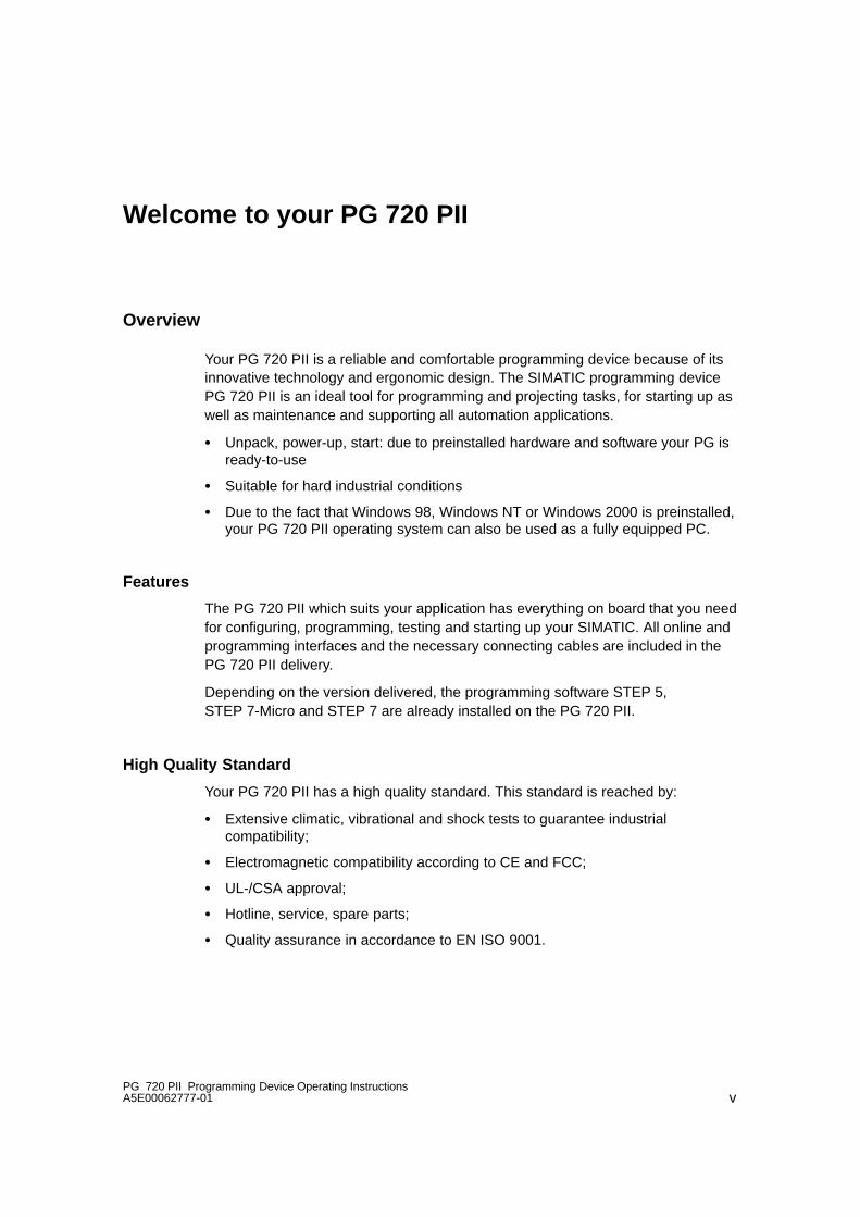
Welcome to your PG 720 PII
Overview
Your PG 720 PII is a reliable and comfortable programming device because of itsinnovative technology and ergonomic design. The SIMATIC programming devicePG 720 PII is an ideal tool for programming and projecting tasks, for starting up aswell as maintenance and supporting all automation applications.
� Unpack, power-up, start: due to preinstalled hardware and software your PG isready-to-use
� Suitable for hard industrial conditions
� Due to the fact that Windows 98, Windows NT or Windows 2000 is preinstalled,your PG 720 PII operating system can also be used as a fully equipped PC.
Features
The PG 720 PII which suits your application has everything on board that you needfor configuring, programming, testing and starting up your SIMATIC. All online andprogramming interfaces and the necessary connecting cables are included in thePG 720 PII delivery.
Depending on the version delivered, the programming software STEP 5,STEP 7-Micro and STEP 7 are already installed on the PG 720 PII.
High Quality Standard
Your PG 720 PII has a high quality standard. This standard is reached by:
� Extensive climatic, vibrational and shock tests to guarantee industrialcompatibility;
� Electromagnetic compatibility according to CE and FCC;
� UL-/CSA approval;
� Hotline, service, spare parts;
� Quality assurance in accordance to EN ISO 9001.

Chapter
viPG 720 PII Programming Device Operating Instructions
A5E00062777-01
Operational Range
The PG 720 PII is a portable programming device. It can be usd for all SIMATICautomation systems in both online and offline operation. The PG 720 PII meets thestrictest requirements by:
� High Level system performance (for example, Intel Pentium II processor)
� High degree of enhanceability (for example, PC-cards, upgradeable processormother board)
� Color TFT display with an excellent contrast and a high degree of brilliance
� MPI/DP interface port for simultaneous connection to SIMATIC S7 and otherautomation systems.
� Depending on the version delivered, preinstalled software for SIMATIC S7 andSIMATIC S5
� Programming interface for S5/S7-EPROM memory
� Ergonomic keyboard with integrated trackball
� Highly portable with a wide range of setup possibilities
� Very robust construction
Setup Possibilities
Different setup options facilitate the operation in an industrial environment:
� Swivel display; the display can be rotated 90°. Even when the programmingdevice is placed on the floor its face can be easily read from above.
� Removable keyboard; the keyboard can be detached from the device to renderopertaion easier to work under diffcult conditions for example, in narrow spaces.
Functions
The software package supplied with the PG 720 PII allows a universal use of thePG 720 PII. The scope of delivery contains:
� Windows 98, Windows NT or Windows 2000 operating system;
� Depending on the version delivered, STEP 7 and STEP 7-Micro/WIN 32programming software and STEP 5/ST.
Additionally the PG 720 PII’s software offers the following operational options:
� Supplementary SIMATIC software
� Software from the entire world of automation
� Any PC software
� Software for Profibus DP
AChapterChapter
viiPG 720 PII Programming Device Operating InstructionsA5E00062777-01
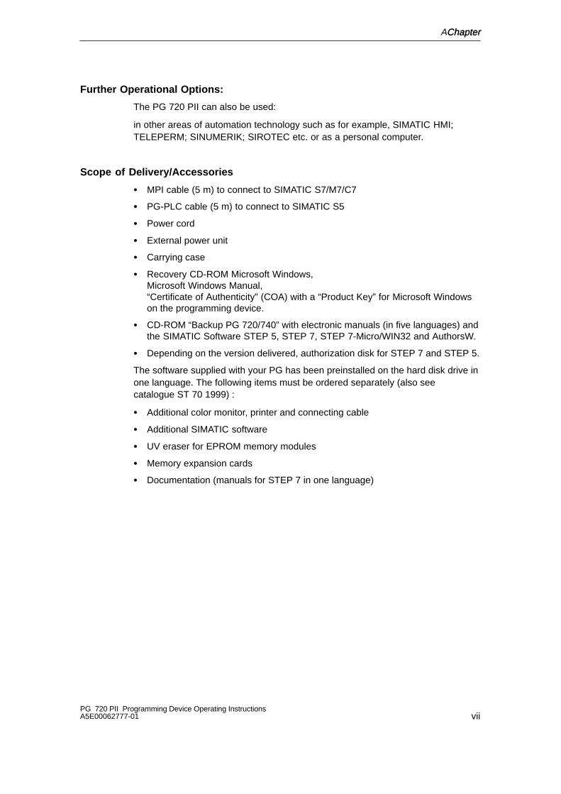
Further Operational Options:
The PG 720 PII can also be used:
in other areas of automation technology such as for example, SIMATIC HMI;TELEPERM; SINUMERIK; SIROTEC etc. or as a personal computer.
Scope of Delivery/Accessories
� MPI cable (5 m) to connect to SIMATIC S7/M7/C7
� PG-PLC cable (5 m) to connect to SIMATIC S5
� Power cord
� External power unit
� Carrying case
� Recovery CD-ROM Microsoft Windows, Microsoft Windows Manual,“Certificate of Authenticity” (COA) with a “Product Key” for Microsoft Windowson the programming device.
� CD-ROM “Backup PG 720/740” with electronic manuals (in five languages) andthe SIMATIC Software STEP 5, STEP 7, STEP 7-Micro/WIN32 and AuthorsW.
� Depending on the version delivered, authorization disk for STEP 7 and STEP 5.
The software supplied with your PG has been preinstalled on the hard disk drive inone language. The following items must be ordered separately (also seecatalogue ST 70 1999) :
� Additional color monitor, printer and connecting cable
� Additional SIMATIC software
� UV eraser for EPROM memory modules
� Memory expansion cards
� Documentation (manuals for STEP 7 in one language)

Chapter
viiiPG 720 PII Programming Device Operating Instructions
A5E00062777-01
Information Referring to these Operating Instructions
Regardless whether you have already worked with a programming device like thePG 720 PII or you are not experienced at all, these operating instructions will helpyou to get familiar with the technical features of your PG. You will learn the mostsignificant elements and operating structures by means of task-oriented sectionsgiving you information to start with almost any possible chapter.
You can find further information in the electronic manual PG 720 PII on the CD-ROM “Backup PG 720/740”. The manual contains information oncommissioning, troubleshooting, hardware and a glossary with explanationsrelating to the programming device.
Basic PLC knowledge or familiarity with mouse-handling, window techniques, pull-down menus etc. may be helpful.
With the help of STEP 7 trainings you can broaden and enhance your knowledgeof the PG 720 PII as well as learn how to create complete automation solutionsusing STEP 7.
How to Use your Operating Instructions
Initial Situation Corresponding Chapter
You have no experience with programmingdevices
Chapter 1 Important Notes
Chapter 2 Starting up and Operating the PG
Chapter 3 Hardware components of thePG 720 PII
You want to prepare your PG forprogramming
Chapter 5 Installing and Operating thePG 720 PII
You want to install additional drivers Chapter 6.4, Installing Drivers
You have to reinstall the software Chapter 6 Reinstallation of the Software
You need support Chapter 8 Hotline Services
You want to connect other hardwarecomponents
Chapter 4 Installing System ExpansionsConnecting Peripheral Devices
You need more information from theelectronic manuals
Chapter 5.4 Electronic Manuals

AChapterChapter
ixPG 720 PII Programming Device Operating InstructionsA5E00062777-01
Conventions
There are different modes to complete your tasks under Microsoft Windows andunder the SIMATIC software. To make it easier for you, we explain how to fulfillyour tasks by means of the menus. Apart from that, the following conventions areused:
Convention Meaning
Command >Bold > Specifies a menu command
“ Inverted Comma” Specifies the name of screen element (forexample, a menu or a command button )
Double-click A rapid and fast double-click on thestandard mouse key (in general the leftmouse key).
Supplementary PG 720 PII Documentation
� PG 720 PII electronic manual on the CD “Backup PG 720/740” that comes withthe PG
� Electronic manuals (complete documentation on CD, in five languages)
� STEP 7 basic package containing of the following manuals: Getting-Started,Programming manual STEP 7, Configuring and Converting Hardware manual.
� Automation system S7-200, System manual

Chapter
xPG 720 PII Programming Device Operating Instructions
A5E00062777-01

1-1PG 720 PII Programming Device Operating InstructionsA5E00062777-01
Important Notes
1.1 Safety Instructions
!Caution
The safety instructions given on the backside of the title page of this manual mustbe observed. Before adding to the PG 720 PII’s functionality by expanding thehardware configuration (see Chapter 4) refer to the electronic manual on theCD “Backup PG 720/740” supplied with your PG 720 PII and observe the relevantsafety instructions.
Notes on Inserting and Removing Modules
Modules containing electrostatically sensitive devices (ESDs) can be identified bythe following label:
Please observe and carefully follow the guidelines mentioned below when handlingmodules equipped with electrostatically sensitive devices:
� Always discharge your body before handling modules equipped with ESDs (forexample by touching a grounded object).
� Devices and tools must be free of static electricity.
� Always pull the power plug and disconnect the battery before connecting ordisconnecting modules (containing ESDs).
� Touch modules fitted with ESDs by their edges only.
� Never touch wiring posts or printed conductors on modules (containg ESDs).
1

Important Notes
1-2PG 720 PII Programming Device Operating Instructions
A5E00062777-01
1.2 Certificates, Directives and Declarations
Notes on the CE Symbol
The following applies to the SIMATIC product described in this operatinginstruction:
EMC Directive
This product fulfils the requirements for the EC directive 89/336/EEC on“electromagnetic compatibility” and the following fields of application applyaccording to this CE symbol:
Field of Application Requirement for
Emitted Interference Noise Immunity
Residential and commercial areas andsmall businesses.
EN 50081-1: 1992 EN 50082-1: 1992
Industry EN 50081-2: 1993 EN 50082-2: 1995
Low Voltage Directive
This product fulfils the requirements for the EC directive 73/23/EEC on“low voltage” and was tested to EN60950.
Declaration of Conformity
The EC declarations of conformity and the documentation relating to this areavailable to the authorities concerned, according to the above EC directive, from:
Siemens AGBereich Automatisierungs- und AntriebstechnikA&D AS E4Postfach 1963D-92209 AmbergTel.: 09621 80 3283Fax: 09621 80 3278
Observing the Setup Guidelines
The setup guidelines and notes on safety given in the manual must be observedon startup and during operation.
Important Notes
1-3PG 720 PII Programming Device Operating InstructionsA5E00062777-01
ISO 9001 Certificate
The quality assurance system for the whole product process (development,production, and marketing) fulfills the requirements of ISO 9001 (corresponds toEN29001: 1987).
This has been certified by the German society for the certification of qualitymanagement systems (DQS).
EQ-Net certificate no.: 1323-01
Software License Agreement
The PG 720 PII is shipped with the software already installed. Please observe therelevant license agreements.
1.3 Certification for the USA, Canada and Australia
Security
One of the following markings on a device is indicative of the correspondingapproval:
Underwriters Laboratories (UL) to the UL 1950 standard.
Canadian Standard Association (CSA) to Standard C22.2. No. 950

Important Notes
1-4PG 720 PII Programming Device Operating Instructions
A5E00062777-01
EMC
USA
Federal Communications CommissionRadio Frequency Interference Statement
This equipment has been tested and found to comply with the limits for a Class A digitaldevice, pursuant to Part 15 of the FCC Rules. These limits are designed to providereasonable protection against harmful interference when the equipment is operated in acommercial environment. This equipment generates, uses, and can radiate radiofrequency energy and, if not installed and used in accordance with the instruction manual,may cause harmful interference to radio communications. Operation of this equipment in aresidential area is likely to cause harmful interference in which case the user will berequired to correct the interference at his own expense.
Shielded Cables
Shielded cables must be used with this equipment to maintain compliance withFCC regulations.
Modifications
Changes or modifications not expressly approved by the manufacturer could void theuser’s authority to operate the equipment.
Conditions of Operations
This device complies with Part 15 of the FCC Rules. Operation is subject to the followingtwo conditions: (1) this device may not cause harmful interference, and (2) this device mustaccept any interference received, including interference that may cause undesiredoperation.
Canada
Canadian Notice
This Class B digital apparatus complies with Canadian ICES-003.
Avis Canadien
Cet appareil numérique de la classe B est conforme à la norme NMB-003 du Canada.
Australia
This product meets the requirements of the AS/NZS 3548 Norm.

Important Notes
1-5PG 720 PII Programming Device Operating InstructionsA5E00062777-01
1.4 Transporting the PG 720 PII
Preparatory Measures
The PG 720 PII is easy to transport. Before transporting it, however, you shouldtake the following measures:
1. Switch the PG 720 PII off.
2. Then, unplug all connecting cables.
3. Close the covers protecting the ports and connections on the right-hand andleft-hand casing side panels.
4. Bring the unit into an upright position.
5. Swing the keyboard up and press it against the front plate of the unit.Make sure that the latches on the left and the right sides snap into place.
6. Use the carrying handle if you only intend transporting the unit over a shortdistance.
7. If you are transporting the PG 720 PII over large distances, pack the unit withall its accessories in the carrying bag supplied.
Transport
Despite the fact that the PG 720 PII is of rugged design, its internal componentsare sensitive to severe vibrations or impact. You must therefore protect yourPG 720 PII against severe mechanical stressing when transporting it.
Use the original packing material if you have to ship the PG 720 PII from onelocation to another.

Important Notes
1-6PG 720 PII Programming Device Operating Instructions
A5E00062777-01

2-1PG 720 PII Programming Device Operating InstructionsA5E00062777-01
Starting up and Operating the PG
2.1 Unpacking and Checking the Scope of Delivery
Unpacking the PG 720 PII
Unpack your PG 720 PII programming device as follows:
1. Remove the packing.
2. Do no throw the original packing away. Keep it in case you have to transport theunit again sometime in the future.
Checking the Contents
3. Check with the packing list to make sure no components are missing.
4. Check the packing and its contents for any shipping or transport damage.
5. Please inform your local dealer of any shipping or transport damages and ofoutstanding items indicated on the packing list.
Recording the Serial Number
6. Your programming device is identified by a serial number (F-Nr.) on the typelabel affixed to the underside of the device. Enter this number in the tablebelow.
If a programming device is stolen and subsequently submitted for repair, therepair center will be able to identify it by the F-Nr..
Enter the Microsoft Windows “Product Key” from the “Certificate ofAuthenticity”
7. Enter the Microsoft Windows “Product Key” from the “Certificate of Authenticity”(COA) in the table. You can find the product key on your programming device.
F-Nr.
Order No.
Microsoft Windows Product Key
2
Starting up and Operating the PG
2-2PG 720 PII Programming Device Operating Instructions
A5E00062777-01
2.2 Choosing Setup Position
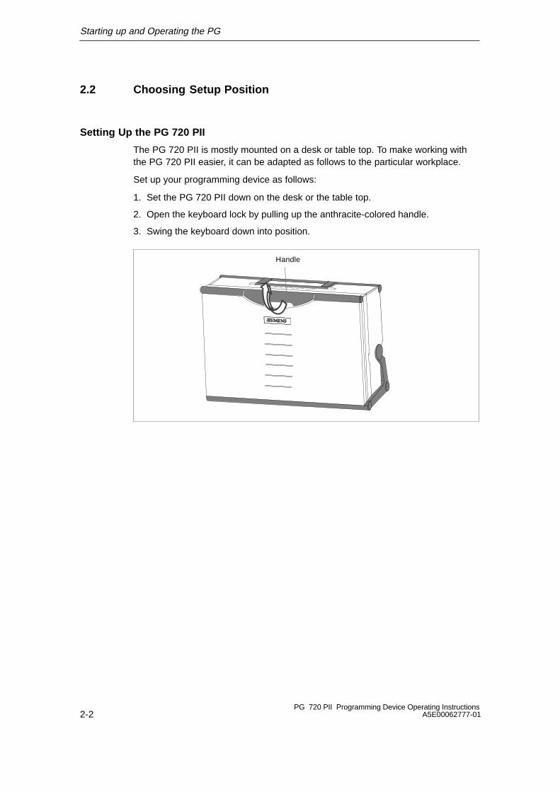
Setting Up the PG 720 PII
The PG 720 PII is mostly mounted on a desk or table top. To make working withthe PG 720 PII easier, it can be adapted as follows to the particular workplace.
Set up your programming device as follows:
1. Set the PG 720 PII down on the desk or the table top.
2. Open the keyboard lock by pulling up the anthracite-colored handle.
3. Swing the keyboard down into position.
Handle
Starting up and Operating the PG
2-3PG 720 PII Programming Device Operating InstructionsA5E00062777-01
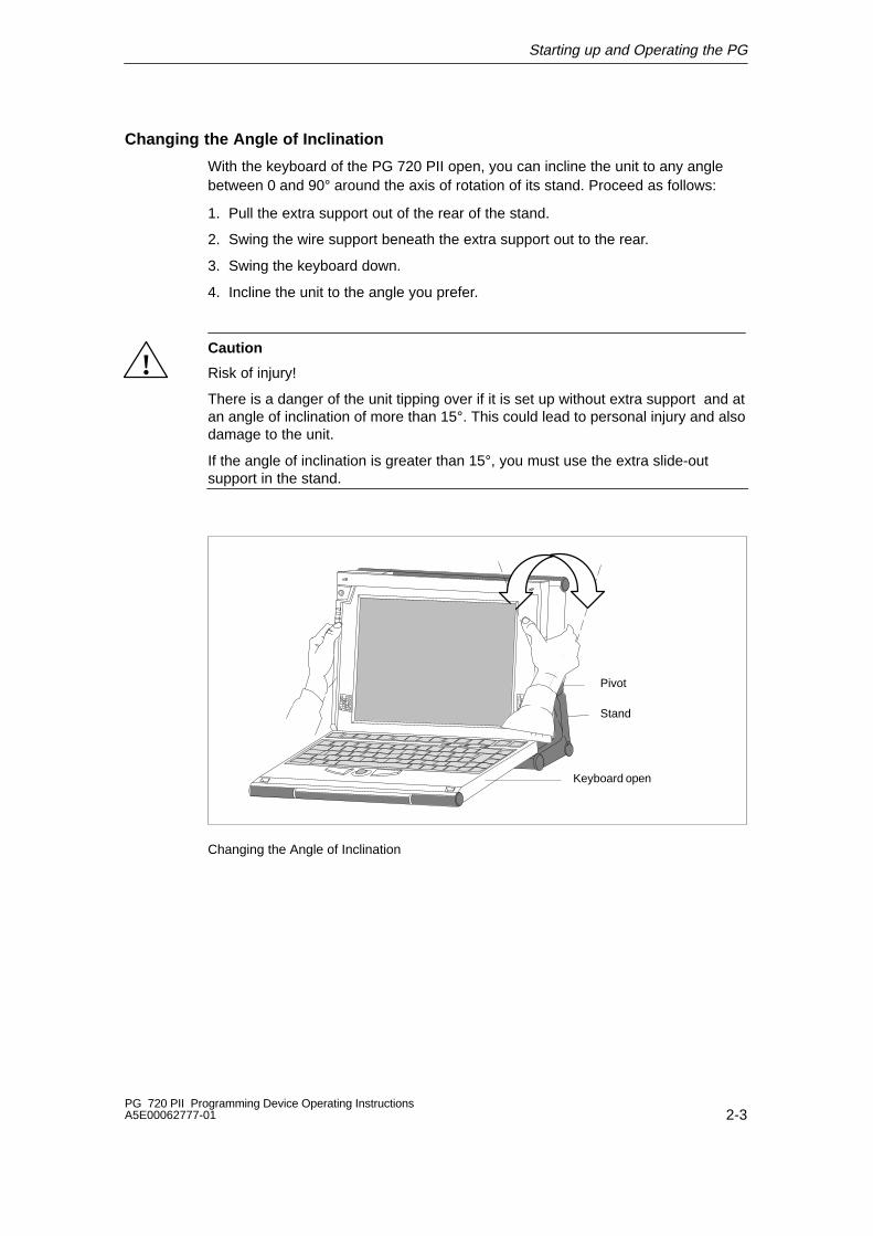
Changing the Angle of Inclination
With the keyboard of the PG 720 PII open, you can incline the unit to any anglebetween 0 and 90° around the axis of rotation of its stand. Proceed as follows:
1. Pull the extra support out of the rear of the stand.
2. Swing the wire support beneath the extra support out to the rear.
3. Swing the keyboard down.
4. Incline the unit to the angle you prefer.
!Caution
Risk of injury!
There is a danger of the unit tipping over if it is set up without extra support and atan angle of inclination of more than 15°. This could lead to personal injury and alsodamage to the unit.
If the angle of inclination is greater than 15°, you must use the extra slide-outsupport in the stand.
Stand
Keyboard open
Pivot
Changing the Angle of Inclination

Starting up and Operating the PG
2-4PG 720 PII Programming Device Operating Instructions
A5E00062777-01
2.3 Operating the PG 720 PII
Connecting to the Power Supply
You can operate the PG 720 PII on 120 V and 230 V power systems. The voltageis selected automatically. In battery mode the programming device draws its powerfrom the built-in rechargeable battery.
Mains Mode
1. Plug the power supply cable supplied with the device into the socket of theexternal power unit and plug the low-voltage jack of the power unit into thedevice’s input socket.
2. Connect the power cable to a socket outlet with a grounded protectiveconductor.
Connection for externalpower unit
VN = 17.5 V DC
Power Supply Connection
Note
The power plug must be disconnected to isolate the unit completely from thesupply.
For operation in Canada and the US, a CSA or UL listed power supply cable must beused.
The external power supply unit is intended for operation with grounded power supplysystems (TN networks according to IEC 364-3).
The unit is not intended for operation with grounded or impedance-groundedsystems (IT networks).

Starting up and Operating the PG
2-5PG 720 PII Programming Device Operating InstructionsA5E00062777-01
Switching on the PG 720 PII
The ON/OFF button (1) has three functions (ON/OFF, wakeup from Save to RAM,and Override).
– Press this button for approximately 1 second to switch on the programmingdevice.
– If the system is in the Save to RAM mode (indicated by the flashingPower LED), press this button for approximately 1 second to reawaken thesystem.
– If a system conflict has occurred and the system fails to react to this button(after approx. 2 seconds), press and hold down the button for approximately7 seconds to force a hard reset (override).
2
1
Press ON/OFF switch for one second to switch on.
BatteryPowerAccessing external memory
Submodule programming active
MPI/DP port active
2 LEDs
Battery:green: Power supply via external power unit
orange: Battery is recharging
red: Battery almost fully discharged
off: Battery is switched off
Power LED green: Programming device is on
Power LED flashing green: Save to DRAM

Starting up and Operating the PG
2-6PG 720 PII Programming Device Operating Instructions
A5E00062777-01
Switching off the PG 720 PII
It is strongly recommended to close all applications and safely turn off theoperating system before switching off the PG 720 PII.
!Warning
Do not switch off the PG 720 PII while being connected to a network, errors indata transfer and loss of data may occur. It could also damage the swap file onyour hard disk and cause loss of data.
Safely turn off the operating system in order to close the swap file and disconnectfrom the network before switching off your PG 720 PII.
To switch off the PG proceed as follows:
1. Close all applications and shut down the operating system.
2. Wait until the operating system issues a message indicating that it is safe toswitch off.
3. Switch off the PG 720 PII by pressing the ON/OFF button.
Note
If you use Windows 98, always use Start > Shut Down in the task bar to switchoff. If you do this the PG 720 PII will switch off automatically when Windows 98shuts down.
Remember that your programming device is not fully de-energized unless youunplug it from the mains supply and disconnect the battery (see Section 4.2 in theelectronic manual).
3-1PG 720 PII Programming Device Operating InstructionsA5E00062777-01
Hardware Components of the PG 720 PII
This chapter provides you with information on hardware components and theirfunctions, such as:
� Right- and left-hand side panel of the device
� Underside of the housing
� Connectors and ports
� Drives
� Memory submodules
� External power unit
� Battery and
� Backup battery
3

Hardware Components of the PG 720 PII
3-2PG 720 PII Programming Device Operating Instructions
A5E00062777-01
3.1 Front
You can access all the important operator controls and displays from the front orsides of the unit. The CD-ROM drive can be accessed from the underside of thedevice.
2
56
7
1
4
8
14
11
913Detail
12
14
PowerAccessing external storagemedium4)
Submodule programming activeMPI/DP port active
6 Keyboard
7 Coverplate for COM1/COM2 port, MPI/DP port, mouse port, and LPT1/printerport 1)
8 Trackball
9 Catches for locking keyboard
10 Pivot
11 Protector strip
12 CD-ROM drive 2)
14 Speakers
LEDsDetail 13
1 On/Off switch button 3)
2 Carrying handle
3 LC display
4 Coverplate for module ports, memory cardports, PCMCIA ports, and floppy disk drive 1)
5 Stand
1) The coverplates are used to protect the ports fromdust, and can be removed and replaced asrequired.
2) Can be accessed from the base when the deviceis turned upside down.
3) Press this button for 1 second in order to switch. on the programming device. A hard reset(override) is performed if you hold down the buttonfor longer than 7 seconds.
4) External storage media: hard disk drive, floppy. disk drive, CD-ROM drive
9 3
10
Battery
Hardware Components of the PG 720 PII
3-3PG 720 PII Programming Device Operating InstructionsA5E00062777-01
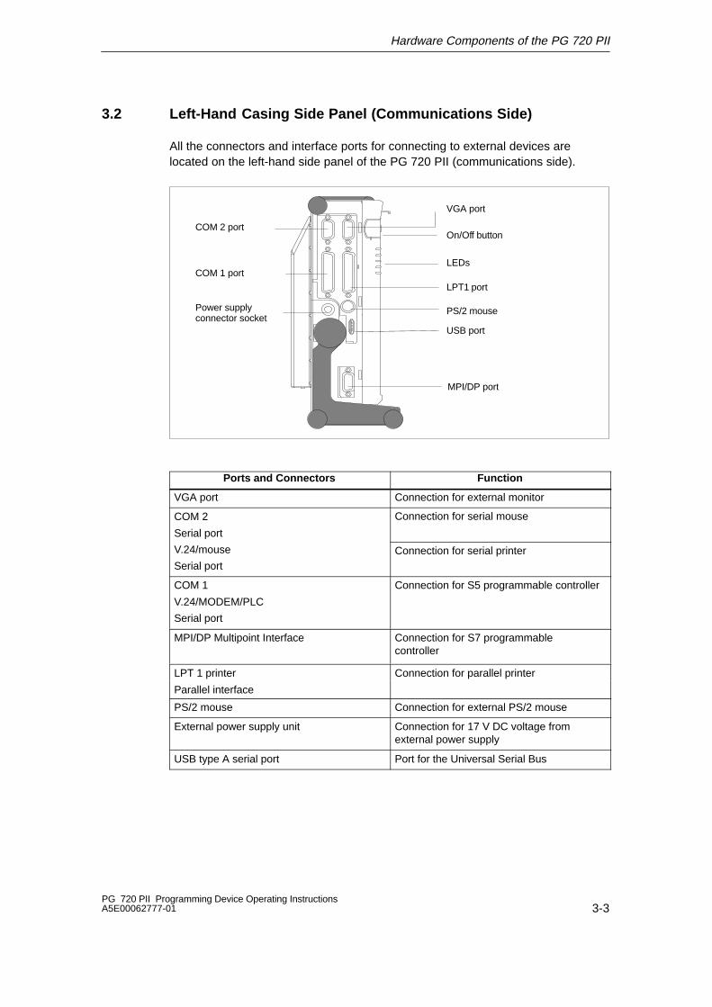
3.2 Left-Hand Casing Side Panel (Communications Side)
All the connectors and interface ports for connecting to external devices arelocated on the left-hand side panel of the PG 720 PII (communications side).
LPT1 port
USB port
VGA port
On/Off button
LEDs
PS/2 mouse
COM 2 port
COM 1 port
Power supplyconnector socket
MPI/DP port
Ports and Connectors Function
VGA port Connection for external monitor
COM 2
Serial port
Connection for serial mouse
V.24/mouse
Serial portConnection for serial printer
COM 1
V.24/MODEM/PLC
Serial port
Connection for S5 programmable controller
MPI/DP Multipoint Interface Connection for S7 programmablecontroller
LPT 1 printer Connection for parallel printer
Parallel interface
PS/2 mouse Connection for external PS/2 mouse
External power supply unit Connection for 17 V DC voltage fromexternal power supply
USB type A serial port Port for the Universal Serial Bus
Hardware Components of the PG 720 PII
3-4PG 720 PII Programming Device Operating Instructions
A5E00062777-01
VGA Port
Please read the note referring to the operation of LC displays and externalmonitors.
NoteThe default setting of the display provides the simultaneous operation of an LCdisplay and an external monitor. The screen display is then optimized to a formatof 800 x 600 pixels. Modes with a lower resolution and text modes are expandedto this format.
To optimize the screen display for an external monitor, select “PG 720 PIIHardware Options” under Setup and set “CRT/LCD selection: CRT enabled”. Aresolution of 1024*768 pixels with a higher refresh rate can then be set.
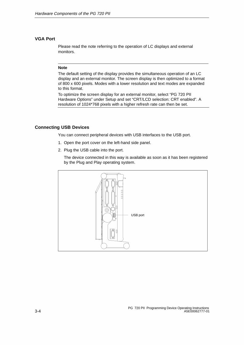
Connecting USB Devices
You can connect peripheral devices with USB interfaces to the USB port.
1. Open the port cover on the left-hand side panel.
2. Plug the USB cable into the port.
The device connected in this way is available as soon as it has been registeredby the Plug and Play operating system.
USB port
Hardware Components of the PG 720 PII
3-5PG 720 PII Programming Device Operating InstructionsA5E00062777-01
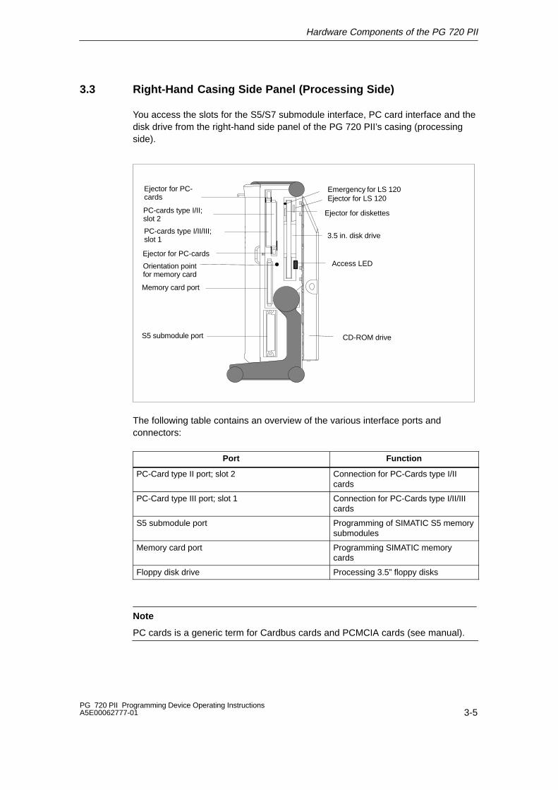
3.3 Right-Hand Casing Side Panel (Processing Side)
You access the slots for the S5/S7 submodule interface, PC card interface and thedisk drive from the right-hand side panel of the PG 720 PII’s casing (processingside).
Emergency for LS 120Ejector for LS 120
S5 submodule port
Ejector for PC-cards
PC-cards type I/II/III; slot 1
Ejector for PC-cards
Orientation pointfor memory card
PC-cards type I/II; slot 2
Memory card port
CD-ROM drive
Access LED
3.5 in. disk drive
Ejector for diskettes
The following table contains an overview of the various interface ports andconnectors:
Port Function
PC-Card type II port; slot 2 Connection for PC-Cards type I/IIcards
PC-Card type III port; slot 1 Connection for PC-Cards type I/II/IIIcards
S5 submodule port Programming of SIMATIC S5 memorysubmodules
Memory card port Programming SIMATIC memorycards
Floppy disk drive Processing 3.5” floppy disks
Note
PC cards is a generic term for Cardbus cards and PCMCIA cards (see manual).

Hardware Components of the PG 720 PII
3-6PG 720 PII Programming Device Operating Instructions
A5E00062777-01
Base Panel
You can access the CD-ROM drive and the rechargeable battery from the base ofthe PG 720 PII device.
CD-ROM drive
Battery
Ventilating Slots
The raised air outlet slots for the ventilation are located above the interface ports.There are also ventilating slots on the underside of the base. These slots must notbe covered and blocked in any way (by carpeting, for instance).
!Caution
Risk of overheating!
If you cover up the slots for the inlet and outlet air in any way, there is a risk thatyour PG 720 PII will be damaged.
Do not place any objects over, or lay them on, the ventilating slots.

Hardware Components of the PG 720 PII
3-7PG 720 PII Programming Device Operating InstructionsA5E00062777-01
3.4 Color Display of the PG 720 PII
Color Display of the PG 720 PII
The display on the PG 720 PII is an TFT color display with a 12.1 in. diagonal(≈ 31 cm) and a resolution of 800 x 600 pixels.
The three primary colors, red, green and blue, can each be displayed in64 different shades. This means that, including all the secondary colors, amaximum of 256k different colors can be displayed.
!CautionRisk of injury!
If a display is damaged , liquid crystal may escape. Do not touch this liquid orallow it to come into contact with your skin in any way, and do not breathe in thevapors. If you do come into contact with the liquid, wash those parts of the skinaffected immediately with alcohol, and rinse with plenty of water. Then consult aphysician right away.
Use only a soft cotton cloth slightly moistened with a mild cleansing agent forglass or an impregnated wipe for spectacles to clean the display. Do not use wateror aggressive solvents (such as alcohol and acetone) and do not spray moistureonto the display.

Hardware Components of the PG 720 PII
3-8PG 720 PII Programming Device Operating Instructions
A5E00062777-01
3.5 Drives
The PG 720 PII is equipped with a 3.5 in. floppy disk drive, a 2.5 in. hard diskdrive, and a CD-ROM drive.
Disk Drive
You can store programs and data on diskettes with the disk drive and load themfrom diskettes into the PG 720 PII.
Note
When a diskette in the FDD is accessed, this status is indicated by the accessLED on the drive and the access LED for external storage media on the front ofthe device.
Wait until the LEDs go out before you remove the diskette from the FDD.
Types of Diskette
You can use the following diskettes:
double sidedhigh density diskette
double sideddouble density diskette
Superdisk
3.5 “ 3.5 “ 3.5 “
1,44 Mbyte (135 TPI) 720 Kbyte 120 Mbyte
The PC recognizes the disk type by the coding. Superdisks can only be used in aLS120 drive.
Handling Diskettes with the Floppy Disk Drive
The diskette is inserted in the disk drive as shown below:
emergency ejector for LS120 drives
ejector for LS120 drives
Ejector
Access LED

Hardware Components of the PG 720 PII
3-9PG 720 PII Programming Device Operating InstructionsA5E00062777-01
Information on the LS120 Disk Drive
Restrictions
P Tools under STEP 5
Data cannot be edited in PCP/M format on the LS120 drive using P Tools underSTEP 5.
Authorization with Authors Vx.x
In order to authorize STEP 5 and other SIMATIC components, use AuthorsW.When using PGs start the taskbar under Start > Simatic > AuthorsW.
Settings in Setup
In order to put the LS120 drive into operation the following settings are valid.These are the default settings for the device.
To open the Setup menu, press function key F2 during the boot sequence. Makethe following settings in Setup:
1. In the “Main” menu, set Diskette A: to “Disable”.
2. In the “Main” menu under Boot Options:
Set the boot sequence as follows:
1 Removable Devices
2 Hard Drive
3 ATAPI CD-ROM Drive
4 Diskette Drive
3. In the “Advanced” menu, set Floppy-Disk-Controller to “Disable”.
4. Boot the programming device with “Save Changes & Exit”.
With these settings the LS120 drive can be addressed in the same way as the1.44 Mbyte floppy-disk drive previously installed.
Hardware Components of the PG 720 PII
3-10PG 720 PII Programming Device Operating Instructions
A5E00062777-01
Usage Notes for LS120 Superdisks
In Floppy disks up to 1.44 Mbytes as well as Superdisks up to 120 Mbytes can beused in LS120 drives.
Note: Track density for Superdisks is10 �m compared with the 120 �m ofconventional disks.
The LS120 recognizes when a Superdisk is in the drive and switches to the highercapacity. With conventional disks, a capacity of 1.44 Mbytes or 720 Kbytes can bereached.
Due to their higher storage capacity, Superdisks are more sensitive to dirt,temperature and shock than conventional diskettes.
Note
In order to achieve a reliable operation and high data security, please note thefollowing during use:
� Store and transport the Superdisk in the protective cassette included. Doingthis will keep dust and dirt from the disk.
� Remove Superdisk from the drive when it is not being read or written to keepdirt particles away from the disk. Do not expose the disk to unnecessarily highoperating temperatures.
Note: A Superdisk can be completely read or written in 15 minutes.
Note
If possible avoid vibration of the device, when using Superdisks. Superdisks aremore sensitive to vibration as a result of their high track density.
Emergency Removal:When the device is switched off, the disk can be forced out by using a pin(forexample, a bent paper clip).
Recommended Superdisks:
The Superdisks available commercially vary in quality. The best results in our quali-fication tests achieved the third generation disks from the company IMATION.
External identification features: blue housing and silver-colored sliding cover.
These Superdisks can be obtained from the following addres.
IMATION corp. IMATION Europe BV IMATION Deutschland GmbH1 Imation Place 1119 PH Schipol-RIJK Hammfelddamm 11Oakdale, MN 55128-3414 41460 NeussUSA Netherland GermanyPhone (888) 466-3456 Tel +31 (0) 20 654 2100 Tel +49 (0) 2131 226 01E-mail [email protected] Fax +31 (0) 20 654 2222 Fax +49 (0) 2131 226 100

Hardware Components of the PG 720 PII
3-11PG 720 PII Programming Device Operating InstructionsA5E00062777-01
Hard Disk Drive
Whenever the hard disk is accessed, the access LED on the front of the unit lightsup.
!Caution
Risk of loss of data and damage to the drive!
Drives are sensitive to vibrations and shock. Any vibrations occurring duringoperation can lead to the loss of data or damage to the drive.
If you intend transporting the unit, switch it off, and wait until the drive has come torest (about 10 seconds) before you move it.
Hardware Components of the PG 720 PII
3-12PG 720 PII Programming Device Operating Instructions
A5E00062777-01
3.6 CD-ROM Drive
The CD-ROM drive enables you to read CDs.
Note
When a CD in the CD-ROM drive is accessed, this status is indicated by theaccess LED on the drive and the access LED for external storage media on thefront of the device.
Wait until the LEDs go out before you remove the CD from the drive.
Opening the Drawer
Swing the PG 720 PII into a horizontal position. The CD-ROM drive is now on theunderside of the programming device. Switch on the programming device. Bybriefly pressing the eject button, the drawer springs out slightly. Now pull thedrawer out until it clicks into position.
Inserting / Removing CDs
Now insert the CD in the drawer with the labeling face up, and press it firmly downinto the center of the turntable. To remove the CD, hold it by the edges and pullupwards.
!Caution
To avoid too much pressure on the open drawer, always hold the drawer at thefront with one hand when inserting or removing a CD.
Closing the Drawer
Push in the drawer until it closes completely. Do not press the eject button.
Note
The EJECT function offered by various applications for opening the CD-ROMdrawer does not work with this drive.
After the drawer has been closed, the CD is tested and the access display light onthe drive starts to flash:
– If the display flashes continually, the CD is faulty but can still be read,
– If the display flashes several times and then remains lit, the CD you have insertedis defective and cannot be read.

Hardware Components of the PG 720 PII
3-13PG 720 PII Programming Device Operating InstructionsA5E00062777-01
CD-ROM Front
12 3 4
1 Access display2 Drawer3 Eject button4 Emergency eject
!Caution
Risk of data loss and damage to the drive!
CD-ROM drives are sensitive to vibrations and shock. Any vibrations occuringduring operation can lead to damage to the drive or CD.
Emergency removalBy inserting a pin (or a paper clip) while the device is switched off, you can forcethe drawer to open.

Hardware Components of the PG 720 PII
3-14PG 720 PII Programming Device Operating Instructions
A5E00062777-01
3.7 SIMATIC Memory Submodules and PC Cards
Please note the following instructions for working with SIMATIC S5 memorysubmodules and SIMATIC memory cards.
!Caution
Risk of damage to submodules!
Do not attempt to remove a card while the ”Submodule programming active” LEDis on. Inserting or removing cards while submodule programming is active canresult in damage to the cards. You cannot work with S5 submodules and memorycards at the same time.
Always discharge your body’s charge of static electricity by briefly touching agrounded object before inserting or removing a card (ESD Guideline: seeSection 1.1 or electronic manual).
Note
Do not attempt to program SIMATIC S5 submodules or SIMATIC memory cardsunless the programming unit is operating on mains power (external power unitconnected). This is the only way of ensuring that the programming session is notinterrupted on account of a low battery.
The programming interface is not enabled unless the programming unit isconnected to the mains supply when it is switched on.
Note
Operating SIMATIC S5 submodules and SIMATIC memory cards simultaneouslyis not permitted. The following table shows the operating modes permitted and themaximum possible current consumption for the PC card interface.
S5 Submodule Port Memory CardPort
PCMCIA PortSlot 1 and Slot 2 5V 12V
S5 memorysubmodule
– PC-Card 1) 1)
– Memory card PC-Card 2) –
– – PC-Card 3) 4)
1. Depends on the S5 memory submodule
2. Max. permissible current in total for both slots 250 mA. . . . . . . . .
3. Max. permissible current in total for both slots 500 mA. . . . . . . . .
4. Max. permissible current in total for both slots 120 mA. . . . . . . . .

Hardware Components of the PG 720 PII
3-15PG 720 PII Programming Device Operating InstructionsA5E00062777-01
Note
Peak currents of 650 mA at 5 V based on 3 s are permitted.Examples of PCMCIA cards connected to PC card interface for
Hard disk 330 mA read/write(Maxtor MXL-131-III) 640 mA spin up 2 s. . . . .
110 mA idle. . . . . . . . . . . . . . . . . . . . . . . Fax/modem 60 mA idle. . . . . . . . . . . . . (Dr. Neuhaus) 140 mA transfer. . . . . . . . . . . Ethernet(XIRCOM) 150 mA. . . . . . . . . . . . . .
SIMATIC Memory Cards
Please note the following instructions while working with memory cards.
!Caution
Risk of damage to memory cards!
When inserting a card, always make sure that the identification mark (a spot) isfacing up (label to rear).
If you try to plug the memory card in the wrong way around, your programmingdevice or memory card will be damaged!
SIMATIC S5 Memory Submodules
Please not the following instructions for working with S5 memory submodules.
!Caution
Risk of damage to S5 memory submodules!
When inserting a memory submodule, always make sure that the printed circuitboard is toward the front.
You could damage the PG or the S5 memory submodule if you attempt to insertthe memory submodule the wrong way round.

Hardware Components of the PG 720 PII
3-16PG 720 PII Programming Device Operating Instructions
A5E00062777-01
PC Cards
Note
PC cards is a generic term for Cardbus cards and PCMCIA cards (see electronicmanual).
Proceed as follows while working with Cardbus-/PC cards:
Ejector for PC-Cards
Ejector for PC-Cards
!Caution
Before inserting PC-Cards please make sure that the PC-Card Ejector iscompletely pressed otherwise the cards e.g. Flash Memory Cards could get stuckin the slot. The PC-Cards can not be inserted correctly.
Always insert the PC card with the label toward the rear of the programmingdevice.
Do not remove the PC card while data transfer is in progress (risk of data loss andsystem crash).
!Caution
Always discharge your body’s charge of static electricity by briefly touching agrounded object before inserting or removing a PC card (see ESD Guideline inSection 1.1 or electronic manual for PG 720 PII).
Otherwise damage could occur.
Hardware Components of the PG 720 PII
3-17PG 720 PII Programming Device Operating InstructionsA5E00062777-01
Installing PC Cards
Note the following when installing these cards:
Note
Depending on the configuration of the PG 720 PII, there may not be any freeinterrupts available for operating PC-Cards. In this case, you must reserveinterrupts in the setup.
To reserve the interrupts, proceed as follows:
Open the ”Advanced” BIOS Setup menu and set the interrupt required by thePC cards to ”reserved” (default is ”available”) at ”PCI/PNP ISA IRQ Resourceexclusion” in the PCI Configuration” line.
The cardbus controller occupies the I/O area from 0x3E0 to 0x3E1.
Hardware Components of the PG 720 PII
3-18PG 720 PII Programming Device Operating Instructions
A5E00062777-01
3.8 External Power Supply
The external power supply supplies power to the PG 720 PII when it is operatedusing 120 V and 230 V mains power. The voltage range is set automatically. Whenthe programming device is run on mains power, the integrated rechargeablebattery is charged automatically. The connecting cable to the PG 720 PII ispermanently connected to the external power supply. A socket on the externalpower supply enables you to connect it to the mains supply.
!Caution
Risk of damage to the device.
The PG 720 PII may only be operated with the correct external power supplyenclosed with the device.
Note
The power plug must be disconnected to isolate the unit completely from thesupply.
For operation in Canada and the USA, a CSA or UL-listed power supply cablemust be used.
For the United States and Canada:
In the United States and Canada the cord must be UL-listed and CSA Labelled.The male plug is a NEMA 5-15 style.
For operation with 120 V:
Use a UL-listed, CSA Labelled Cord Set, consisting of a min. 18 AWG. Type SVTor SJT three conductor flexible cord, max. 4.5 m (15 feet) in length and a parallelblade grounding type attachment plug, rated 15 A, min 125 V.
For operation with 240 V (within the USA):
Use a UL-listed, CSA Labelled Cord Set, consisting of a min. 18 AWG. Type SVTor SJT three conductor flexible cord, max. 4.5 m (15 feet) in length and a tandemblade grounding type attachment plug, rated 15 A, 250 V.
For operation with 230 V (outside of USA):
Use a Cord Set consisting of a min 18 AWG cord and grounding type attachmentplug rated 15 A, 250 V. The connecting cable should have the appropriate safetyapprovals for the country in which the equipment will be installed and marked.
The unit is intended for operation with grounded power supply networks (TN networks, VDE 0100 part 300 or IEC 364-3).The unit is not intended for operation with non-grounded or impedance-groundedsystems.
The connecting cable must meet the necessary safety requirements in therespective country.

Hardware Components of the PG 720 PII
3-19PG 720 PII Programming Device Operating InstructionsA5E00062777-01
3.9 Rechargeable Battery
The PG 720 PII has an integrated NiMH (nickel metal hydride) rechargeablebattery. This makes the device portable, meaning you can use it without theexternal power supply. A charge-status indicator is integrated into the battery.
Note
Do not start a work session in battery mode unless the battery is fully charged.This is the only way of ensuring that the full on-battery operating time is availableand that you will be warned in good time when battery power is low. The batteryhas electronic circuitry for showing the current charge status. You can view thecharge status under Windows 98. The indicator has to be recalibrated from time totime (see electronic manual, Section 4.2 Battery Mode).
If the error message “Battery needs calibration cycle” is generated after power on,then calibration must be carried out. Acknowledge the error message with theF1 key and execute a teach-in cycle (see also Section 4.2 in the manual).
The procedure for recalibrating is as follows:
1. Charge the battery until the charge-status indicator shows 100%.
2. Leave the programming device switched on to drain the battery: theprogramming device will switch itself off when the battery is discharged.Remember to disconnect the power unit from the PG 720 PII so that thebattery can discharge.
3. Once the programming device has switched itself off, start another chargecycle by reconnecting the external power unit to the PG 720 PII. The teach-incycle terminates automatically approximately 10 minutes later.
As soon as the device is connected to the network via the power supply unit, adischarged battery is recharged: if the device is switched off, the battery can berecharged within two hours; if the device is switched on with reduced chargingcurrent, this takes about eight hours.
When you switch off the programming device the battery is recharged for a shorttime (orange LED on) for safety’s sake. This ensures that the battery is fully char-ged.
You should not let the battery become too low. Switch the device off with the on/offswitch after use. If the device is not used for some time, for example, severalweeks, you should remove the battery plug. This is the best way of saving thebattery and ensuring it has a longer life, since it has no connection to the device.The battery can be found behind the battery cover on the underside of the device.It can be accessed when the device is placed in a horizontal position.
The charging process may finish too early if the device is subjected to a significantchange in temperature, or when operating in high ambient temperatures(max. 40°C). You should wait until your device has been acclimatized beforecharging the battery.

Hardware Components of the PG 720 PII
3-20PG 720 PII Programming Device Operating Instructions
A5E00062777-01
!Caution
Do not use a battery other than that supplied with the PG 720 PII.
When disposing of used rechargeable batteries, please observe your localregulations for waste disposal.
Always comply with the ESD Guideline (see Section 1.1 or the electronic manualfor the PG 720 PII).
4-1PG 720 PII Programming Device Operating InstructionsA5E00062777-01
Installing System Expansions,Accessories and Spare Parts
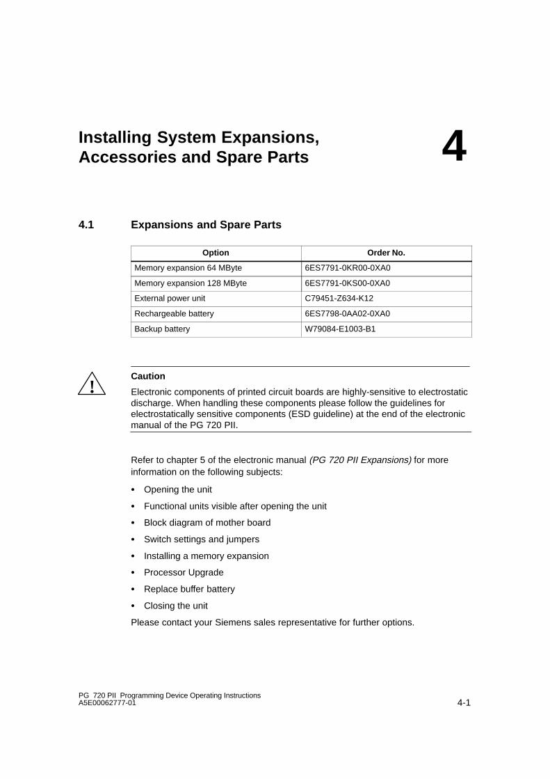
4.1 Expansions and Spare Parts
Option Order No.
Memory expansion 64 MByte 6ES7791-0KR00-0XA0
Memory expansion 128 MByte 6ES7791-0KS00-0XA0
External power unit C79451-Z634-K12
Rechargeable battery 6ES7798-0AA02-0XA0
Backup battery W79084-E1003-B1
!Caution
Electronic components of printed circuit boards are highly-sensitive to electrostaticdischarge. When handling these components please follow the guidelines forelectrostatically sensitive components (ESD guideline) at the end of the electronicmanual of the PG 720 PII.
Refer to chapter 5 of the electronic manual (PG 720 PII Expansions) for moreinformation on the following subjects:
� Opening the unit
� Functional units visible after opening the unit
� Block diagram of mother board
� Switch settings and jumpers
� Installing a memory expansion
� Processor Upgrade
� Replace buffer battery
� Closing the unit
Please contact your Siemens sales representative for further options.
4
Installing System Expansions, Accessories and Spare Parts
4-2PG 720 PII Programming Device Operating Instructions
A5E00062777-01
Installing SO-DIMM Cards
Plug the DIMM memory cards in as follows:
1. First open the unit as described in Chapter 5 of the manual PG 720 PIIProgramming Device. The manual is available in electronic form on theCD-ROM “Backup PG 720/740” supplied with your programming device.
!Caution
Risk of damage!
NWork on the open programming device must be performed by qualified persons, asotherwise your warranty will be voided. Siemens-authorized maintenance and repaircenters provide the necessary qualified service. Their addresses are available onrequest from the SIMATIC Customer Support Hotline.
2. Insert the card into the socket. Note the recesses in the connector side of theSO DIMM card (to prevent installation wrong way round).
3. Press the card lightly and tilt it downwards until it locks into place.
!Caution
Risk of damage!
The cards must be plugged in tightly, otherwise they may be damaged.
4.2 Backup Battery
A backup battery (3.6 V lithium battery) powers the hardware clock even when thepower supply to the device is switched off.
!Warning
Risk of severe personal injury or property damage, danger of release of harmfulsubstances.
Danger of explosion if battery is not handled properly; incorrect disposal of usedbatteries can cause the release of harmful substances.Do not throw a new or discharged lithium battery into an open fire, do not solderon to the body of the battery. Do not recharge the battery and do not open thebattery by force.The correct lithium battery is available from Siemens(Order No.: W79084-E1003-B1).Return used lithium batteries to the manufacturer/recycler or dispose of themaccording to local regulations.

5-1PG 720 PII Programming Device Operating InstructionsA5E00062777-01
Installing and Operating the PG 720 PII
5.1 Preparing Startup
Setting Up the PG (Desk-Top Mounting)
Set up your programming device as follows:
1. Set the PG 720 PII down on the desk-top
2. Open the keyboard lock by pulling up the antracite-colored handle.
3. Swing the keyboard down into position.
Connecting to the Power Supply
The external power unit supplied with your PG 720 PII is of the auto-sensing typefor connection to either 120 V or 230 V mains socket outlets.
1. Plug the power supply cable supplied with the device into the socket of theexternal power unit and plug the low-voltage jack of the power unit into thedevice’s 17 V input socket.
2. Connect the unit to a socket outlet with a grounded protective conductor.
Powering Up the PG 720 PII
Both the operating system and system software supplied with the PG 720 PII arepreinstalled on the hard disk and are set up by the time you power up your PG forthe first time. Depending on the version of the PG 720 delivered, there is notime-consuming installation of the operating system and the SIMATIC software(STEP 7, STEP 7-Micro/Win und STEP 5) any more, just unpack the PG, switch iton and start your programming tasks. The SIMATIC software is not installed in allversions.
� To power up the device hold down the On/Off switch for ON/Power Standby onthe front side for at least one second (also see Section 2.3). When powering upthe device you have to distinguish between the following:
– Initial start to set up the PG 720 PII’s software and a
– Complete restart after initial start and authorization.
5

Installing and Operating the PG 720 PII
5-2PG 720 PII Programming Device Operating Instructions
A5E00062777-01
5.2 Cold Start of the PG 720 PII
Installing the Operating System
When powering up the PG 720 PII for the first time the operating system is set upautomatically (depending on the version delivered: Windows 98, Windows NT orWindows 2000). Please proceed as follows:
1. Switch on the PG 720 PII.
2. The PG executes a self-test. During self-test the following message appears onthe screen:
Press <F2> to enter SETUP
Wait until the message disappears and follow the instructions displayed on thescreen.
3. Enter the user information (name, company).
4. Enter your product key. The product key can be found on the device in the line“Product Key” of the “Certificate of Authenticity”.
Note
Never switch off your PG before software installation has been completed in orderto avoid the loss of any software components which are essential for the regularoperation of the device.
Do not change the BIOS default values.
Startup under Windows 98
The operating system is set up once you have entered the requisite information.The Welcome to Windows 98 screen helps you to get familiar with the Desktop -user interface.
Now the user interface is displayed following system startup every time you powerup or reset the PG.
You can find information for the installation, login, password entry and registrationin the manual “Getting Started Microsoft Windows 98” in Chapter 2 “Windows 98Installation”.
Startup under Windows 2000
After you have entered the requisite information and the operating system hasbeen set up, the PG will be restarted.
Via the “Getting Started with Windows 2000” program you can get acquainted withWindows 2000.
You can find information on setting up Windows 2000 Professional or a user ac-count, and on configuring the computer as well as information about Windows2000 Professional in the manual “Microsoft Windows 2000 Professional”.
Installing and Operating the PG 720 PII
5-3PG 720 PII Programming Device Operating InstructionsA5E00062777-01
Your device is set to English menus and dialogs and a US keyboard whendelivered. You can set another language and keyboard via the control panel withthe dialog Start >Settings > Control Panel > Regional Options > tab ”General ”,box ”Menus and dialogs”> tab ”Input locales”, box ”Input language” .
Startup under Windows NT
You can start Windows NT by simultaneously pressing Ctrl + Alt + Del after youhave entered the requisite information and the operating system has been set up.
You can find information for the installation, login, administrator account, passwordentry, creation of an emergency disk and startup of Windows NT in the manual“Microsoft Windows NT” in part 2 “Installation“.
Authorization
To use the STEP 5 and STEP 7 programming software you have to install anauthorization. Without this authorization it is not possible to run this protectedsoftware until the authorization for the respective program or program package isdetected on the hard disk drive of your PG 720 PII.
With versions delivered with STEP 5 and STEP 7 programming software, theauthorizations can be found on the Authorization disk that comes with your PG.
To perform the authorization:
� Insert the authorization disk in drive A:
� Click ”Start” on the Windows task bar and
� select the menu command Simatic > AuthorsW > AuthorsW to open theauthorization tool which will guide you through the installation routine of theauthorization. Copy the STEP 5 and STEP 7 authorization by selecting “All“.
Note
Keep the Authorization disk in a safe place so that you can save the authorizationsto disk.
Installing and Operating the PG 720 PII
5-4PG 720 PII Programming Device Operating Instructions
A5E00062777-01
5.3 Complete Restart of the PG 720 PII
Overview
Once the PG 720 PII’s operating system is set up, the user interface of theoperating system is displayed following system startup every time you switch on orreset the PG. You can start with your programming tasks immediately after startingyour SIMATIC programs.
Note
SIMATIC Software programs are not on all versions delivered.
Starting the SIMATIC Software Programs
STEP 5/ST
� Click ”Start” on the Windows task bar and
� select the desired programm choosing Simatic > STEP 5.
Please note that you have to install the authoization disk before working withSTEP 5/ST (see Section 5.2).
STEP 7
� Click on the icon “SIMATIC Manager” on the Windows desktop
or click “Start” and select the desired program by choosing Simatic > STEP 7.
STEP 7-Micro/WIN 32
� Click ”Start” on the Windows task bar and select the desired program bychoosing Simatic > STEP 7-MicroWIN 32 .
Note
When you use the P Tools (for editing PCP/M files) supplied with STEP 5/ST,remember that these are not fully supported by the Windows 98, Windows NT andWindows 2000 operating systems nor by LS120 diskette drives. If you use theP Tools, we recommend that you use MS-DOS, Windows 3.x or Windows 95 andstandard 1.44 Mbyte floppies.

Installing and Operating the PG 720 PII
5-5PG 720 PII Programming Device Operating InstructionsA5E00062777-01
5.4 Electronic Manuals
Overview
The PG comes with different electronic manuals. You can find :
� the device description for the PG 720 PII on the CD “Backup PG 720/740”located in the directory “Manuals”
� further documents after installing the SIMATIC software selecting Start >Simatic > S7 Manuals
The Adobe Acrobat Reader
To read or to print out these manuals you need the Adobe Acrobat Reader. TheAdobe software located in the following directory:
C:\Acrobat3\
is preinstalled and is set up and activated by double-clicking on any electronicmanual.
Reading the PLC manuals
To read the PLC manuals, start the program “Welcome.pdf” on yourCD “Backup PG 720/740”.
Note
It is recommended to print out the PGs product information and keep it togetherwith the operating instructions for future reference.

Installing and Operating the PG 720 PII
5-6PG 720 PII Programming Device Operating Instructions
A5E00062777-01

6-1PG 720 PII Programming Device Operating InstructionsA5E00062777-01
Reinstallation of the Software
6.1 Cause / Remedy
In case of software errors reinstall your software using the Recovery Windows CDand CD “Backup PG 720/740”.
To restore all directories and files that were copied to your hard disk after the firstset up proceed as follows:
1. If it is possible to save your authorization proceed as described below.
2. If it is not possible to save your authorization please contact the customersupport hotline (see Chapter 8). They will provide you with the informationneccessary for your authorization.
Then proceed as described in Section 6.2.
Saving Authorization on Diskettes
Please proceed as follows:
� Insert authorization disk in drive A
� Click ”Start” on the Windows task bar and
� Select Simatic > AuthorsW > AuthorsW to open the authorization tool whichwill help you to save all authorizations on your authorization disk.
Note
The authorization disk and the authorization tool are not delivered with all versions.
6

Reinstallation of the Software
6-2PG 720 PII Programming Device Operating Instructions
A5E00062777-01
6.2 Restoring the Hard Disk (Data Deleted)
6.2.1 Creating Partitions under Windows 98
After installing a new hard disk it is necessary to create partitions with the program“FDisk” when the partitions have errors or need to be changed.
Note
By deleting or creating partitions or logical DOS-hard drives all saved data is loston the hard disk. All drives on the hard disk will be erased.
The hard disk is delivered with the following installed (only for versions deliveredwith Windows 98):
– a partition of Type PRI DOS, System FAT 16 with 2045 MB orFAT 32 with 4090 MB (depending on the version),
– a Partition of Type EXT DOS, System FAT 32,
– a Partition of Type Non-DOS with 266 MB for the ”Save to Disk” Function forthe “Standby-Mode”.
Information on the FAT 32 file system can be found in Chapter 6 of the manual“Getting Started Microsoft Windows 98”.

Reinstallation of the Software
6-3PG 720 PII Programming Device Operating InstructionsA5E00062777-01
To restore the partitions to their original condition, please do the following:
Primary Partition
1. To boot from the Recovery Windows 98 CD proceed as follows: When themessagePress <F2> to enter Setup
appears on the screen press the ESC key. After initialization a boot menu toselect the boot options is displayed.
2. Select “4. ATAPI CD-ROM Drive”.
3. When “Microsoft Windows 98 Startup Menu” is displayed, select “2. Boot for FDISK, FORMAT or Windows 98 Setup”.
4. Start the Microsoft Windows 98 hard disk configuration program with”A:\>FDisk” .Select the dialog box for enable large disk support for installing
– a FAT16 partition “activate support (Y/N)...? [ N ] ” for No
– a FAT32 partition “activate support (Y/N)...? [ Y] ” for Yes.
5. Create a primary DOS-Partition of 2045 MB for a FAT 16 file system or with4090 MB for a FAT 32 file system. Answer the question “Do you wish to use themaximum available size...” with
– for a 2045 MB FAT16 partition [Y] for Yes,
– for a FAT32 partition [ N] ” for No and the partition size 4090 MB.
6. In order to continue with the next step “Create a Save to Disk Partition” theprimary partition needs to be formatted.Use the Windows 98 CD to boot as described in steps 1 to 3 above and thenformat drive C: with the program “Format”.Type: ”A:\>Format C:”.
Reinstallation of the Software
6-4PG 720 PII Programming Device Operating Instructions
A5E00062777-01
Creating a Save to Disk Partition
Note
Creating this partition is only possible with a formatted primary partition.
To recreate a Save to Disk Partition for the function “Standby-Mode” you have to,
� Use the Recovery Windows 98 CD to boot as described in steps 1 to 3 above,
� Insert the CD-ROM “Backup PG720/740” in the CD-drive,
� Run the batch file “Makes2D.bat” in the directory R:\Drivers\PG720P2\PHDisk(the CD drive has the drive letter R:) by entering the following DOS commandsand confirming them with the Enter key:
– “R:” (change to CD-ROM Drive),
– “DIR” (so the CD-change will be noticed),
– “CD Drivers\PG720P2\PHDisk”
– “Makes2d.bat”
By doing this an area of 266 MByte for the function “Save to Disk for StandbyMode” will be reserved.
Creating an Extended Partition
In order to create an extended partition, you have to first boot from the RecoveryWindows 98 CD as described in steps 1 to 3 above.
Using ”A:\>FDisk” start the Microsoft Windows 98 hard disk configuration program.
Select the dialog box for large disk support. “Do you wish to enable large disksupport (Y/N)...? [Y] for Yes.
Create an extended DOS partition for the rest of the disk space.

Reinstallation of the Software
6-5PG 720 PII Programming Device Operating InstructionsA5E00062777-01
6.2.2 Creating Partitions under Windows 2000
After installing a new hard disk it is necessary to create partitions when they parti-tions have errors or need to be changed.
Note
By deleting or creating partitions all saved data is lost on the hard disk. All driveson the hard disk will be erased.
The hard disk is delivered with the following installed (only for versions deliveredwith Windows 2000):
– a partition with the FAT32 file system with 4090 Mbytes,
– a partition with the NTFS file system.
To restore the partition to its delivery state, proceed as follows:
Primary Partition, FAT 32 File System
1. To boot from the Recovery Windows 2000 CD-ROM press ESC when the BIOSmessagePress <F2> to enter Setupappears. After initialization a boot menu screen form to select the boot optionsis displayed.
2. Select ”4. ATAPI CD-ROM Drive”.
3. Select ”2. Boot for FDISK, FORMAT or Windows 2000 Setup” in the ”MicrosoftWindows 98 Startup Menu” screen form.
4. Start the Microsoft Windows 98 hard disk configuration program with”A:\>FDisk”. In the screen form select “Do you wish to enable large disk support (Y/N)...? [ Y ]” for Yes to support data media with large memory capacity.
5. Create a primary DOS partition with 4090 MB. Enter [N] for “No” for thequestion ”Do you want to use the maximum memory size available for theprimary DOS partition and do you want to activate this partition?” and set thepartition size to 4090 MB.
6. To format the partition from the Recovery Windows 2000 CD, as describedabove in steps 1 to 3, reboot and then format drive C: with the “Format”program. Enter:”A:\>Format C:”(A: is the CD-ROM drive).
The Windows 2000 setup is described in Section 6.5. In the Windows 2000 setupor under Windows 2000 the FAT 32 file system can be changed to a NTFS filesystem with the function “Format”.
Reinstallation of the Software
6-6PG 720 PII Programming Device Operating Instructions
A5E00062777-01
Creating an Extended FAT 32 Partition
In order to create an extended partition you have to boot from the RecoveryWindows 2000 CD as described above in steps 1 to 4.
Create an extended DOS partition for the rest of the disk space.
Under Windows 2000, the FAT 32 file system can be changed to a NTFS filesystem with the function “Format”.
6.2.3 Creating Partitions under Windows NT
After installing a new hard disk it is necessary to create partitions when they parti-tions have errors or need to be changed.
Note
By deleting or creating partitions all saved data is lost on the hard disk. All driveson the hard disk will be erased.
The hard disk is delivered with the following installed (only for versions deliveredwith Windows NT):
– a partition of with the FAT16 file system with 2045 Mbytes,
– a partition of with the NTFS file system.
The creation of partitions is done under the Windows NT setup program. Startingthe Windows NT setup is described in chapter 6.6.

Reinstallation of the Software
6-7PG 720 PII Programming Device Operating InstructionsA5E00062777-01
6.3 Installing the Operating System Windows 98
You should only follow these steps when you wish to upgrade from Windows 2000to Windows 98 or install Windows 98.
The operating system can be reinstalled or restored using the“Recovery Microsoft Windows 98” CD-ROM.
This CD contains encoded data which can only be transferred onto aSIEMENS SIMATIC programming device.
Data transfer is carried out with the OEMSETUP.EXE program on the CD-ROM or,after booting, from the CD-ROM with the Recovery function.
The ADD-ONS, CDSAMPLE, DRIVERS, TOOLS and TOUR folders on the”Recovery Microsoft Windows 98” CD-ROM are not encoded. Thus, theseprograms can always be executed directly from the CD.
After transferring the required data to the hard disk, the operating system can beinstalled using the Windows 98 setup program. The Windows 98 setup can bestarted by entering:HD:\>WIN98\SETUP.EXE(HD: drive on which the WIN98 folder was transferred to).

Reinstallation of the Software
6-8PG 720 PII Programming Device Operating Instructions
A5E00062777-01
Windows 98 Installation Sequence
If a Windows operating system is already installed or if the programming devicehas been started with a bootdisk, the transfer of the data takes place using theprogram OEMSETUP.EXE. To do this, start the program OEMSETUP.EXE on therecovery CD and continue the sequence as of point 5.
If there is no operating system installed, then please do the following:
1. Insert the Recovery CD-ROM Microsoft Windows 98 in the CD-ROM drive andswitch on the PLC.
2. To boot from the recovery CD proceed as follows: When the messagePress <F2> to enter Setup
appears on the screen press the ESC key. After intialization a boot menu toselect the boot options is displayed.
3. Select “4. ATAPI CD-ROM Drive”.
4. When “Microsoft Windows 98 Startup Menu” is displayed, select “1. Boot for CD-Recovery”.
5. You have to acknowledge the “SIEMENS End User License Agreement” withthe F8 function key. Pressing ESC allows you to decline the agreement andcancels the installation.
6. In the next screens you can select the components which are to be copied fromthe CD to the hard disk. Transfer of at least the folder “WIN98” is necessary forthe Windows98 installation or setup.
7. A selection of disk drives for the data transfer is next offered. The disk driveselected is not the installation drive for Windows. It is the drive on which thenecessary installation files and extensions are saved. You need approximately250 MB of additional memory for the Windows setup following the transfer.During a standard installation Windows 2000 is installed on drive C:. Therefore,please make sure when selecting a drive that there is enough available memoryon drive C: after the data transfer.
8. You can start the Windows98 setup after the data transfer andacknowledgement of the completion message via the programHD:\WIN98\SETUP.EXE(HD: drive on which the folder WIN98 was transferred to).
For further information on the installation of Windows 98 refer to Chapter 2“Installing Windows 98” of the “Getting Started Microsoft Windows 98” manual.
Follow the instructions given in section “Performing a New Installation”.

Reinstallation of the Software
6-9PG 720 PII Programming Device Operating InstructionsA5E00062777-01
6.4 Installing Drivers under Windows 98
In order to add or change the device driver of any hardware component proceed asfollows:
Procedure
� Click “Start” , point to “Settings”, click “Control Panel” , then double-click“System” .
� Click the “Device Manager” tab, click on the plus sign next to the hardware typeand then double-click on the selected hardware component.
� Click the “Driver” tab and then click “Update Driver”, then follow the instructionsthat appear on your screen.
� The “Driver” tab may not be available for some devices. In this case try tochange the driver by double-clicking on the desired hardware icon in “Controlpanel”.
Installing Sound Drivers
If the sound controller is not recognized as an “ESS Solo-1 PCI Audio Device”during the Windows 98 setup program, Windows stops the setup with the message“The Wizard searches for updated drivers for: PCI Multimedia Audio Device“. If thishappens, proceed as follows:
1. Insert the CD “Backup PG 720/740” in the CD-ROM drive and click on “Next”.
2. Select “Search for a better driver than the one your device is using now.(Recommended)” and then “Next”.
3. If necessary, select the check box “Specify a location” with a mouse click. Enterthe path for the driver data (HD: drive letter for the CD-ROM drive)HD:\DRIVERS\PG720P2\AUDIO.W98 and then click on “Next”
4. The controller will now be recognized as an “ESS Solo-1 PCI Audio Device” .Click on “Next”. Windows 98 will now copy the sound driver into the correctdirectory on your system.
5. Confirm with “Finish”
6. Answer the question if you wish to restart with “Yes”.

Reinstallation of the Software
6-10PG 720 PII Programming Device Operating Instructions
A5E00062777-01
Sound Driver Installation after Installing Windows
1. Please observe the following instructions to install the sound drivers located inthe directory
C:\DRIVERS\AUDIO.W98\ENG or located in the directoryDRIVERS\PG720P2\AUDIO.W98\ENG of the suppliedCD “Backup PG 720/740”.
2. Please read the file Readme.txt before you start installation.
3. Insert the CD “Backup PG 720/740” and go to the directory[CD-ROM-drive]:\DRIVERS\PG720P2”\AUDIO.W98 in the Explorer.
4. Double click on the icon “Setup.exe”.
5. Click “Next”
6. Click on “Upgrade Drivers” and then click on “Next”.
7. The audio driver will now be copied into the correct directory on your system.
8. You will be asked if you wish to restart your computer. Select “Yes, I want torestart my computer now” and then click on “Finish”.
Windows will now be restarted.
9. Click “Next”.
10.Choose “Search for the best driver for your device” and then “Next”.
11.Click on the check box “Specify a location” if neccessary. Enter the directory forthe driver path”[CD-ROM-drive]:\DRIVERS\PG720P2\AUDIO.W98 and then click “Next”
12.Click “Next”
13.Click “Finish”.
The following components will automatically recognized and be immediatelyavailable.
� ESS Solo-1 PCI Audio Drive
� ESS Solo-1 DOS Emulation
Reinstallation of the Software
6-11PG 720 PII Programming Device Operating InstructionsA5E00062777-01
PC Card Driver Installation
If the Windows 98 setup program does not recognize the CardBus Controller as“Texas Instruments PCI-1225 CardBus Controller”, then Windows uses it’s generaldriver “Generic CardBus Controller”. In this case proceed as follows:
1. Insert the CD “Backup PG 720/740” in the CD-ROM drive and when the“Generic CardBus Controller” is recognized, click on “Next”.
2. Select “Search for a better driver than the one your device is using now.(Recommended)” and then “Next”.
3. Click on the check box “Specify a location” if necessary. Enter the directory forthe driver path \DRIVERS\PG720P2\PCCARD.W98and click on “Next”.
4. The controller wil now be recognized as “Texas Instruments PCI-1225 CardBusController”. Click on “Next”. Windows 98 will now copy the PC Card driver in thecorrect directory on your system.
5. Confirm with “Finish”
6. Answer the question if you wish to restart with “Yes”.
Reinstallation of the Software
6-12PG 720 PII Programming Device Operating Instructions
A5E00062777-01
PC Card Driver Installation after Installing Windows
1. Use these instructions to install a driver from the directoryC:\DRIVERS\PCCARD.W98 or from the CD “Backup PG 720/740”\DRIVERS\PG720P2\PCCARD.W98 respectively.
2. Please read the file Readme.txt before you start installation.
3. Insert the CD “Backup PG 720/740”. Click on “Start”, then “Settings” and then“Control Panel”.
4. Select “System” and click on the tab “Device Manager”.
5. Double click on the entry “PCMCIA Socket”.
6. Two “Generic CardBus Controller’s” will be shown. Select one of them byclicking the left mouse button. Then click the right mouse button. A popup menuappears. Select “Remove” and confirm with “OK”.
7. Double click on the entry “PCMCIA Socket”
8. This time only one “Generic CardBus Controller” will be shown. Select this witha left mouse click.
9. Click on the menu command “Properties” and then on the tab “Driver”.
10.Select “Update Driver” and then “Next”.
11.Select “Search for a better driver than the one your device is using now.(Recommended)” and then “Next”.
12.Click on the check box “Specify a location” if necessary. Enter the directory forthe driver path \DRIVERS\PG720P2\PCCARD.W98and click on “Next”.
13.The controller will now be recognized as “Texas Instruments PCI-1225 CardBusController”. Click on “Next”. Windows 98 will now copy the PC Card driver to thecorrect directory on your system.
14.If the window “Insert Windows 98 CD” appears, insert the CD and go to thefolder “ \Win98”.
15.Install the same driver as described above for the second “Generic CardBusController”.
16.Confirm with “Finish”.
17.Close all windows and restart Windows 98.

Reinstallation of the Software
6-13PG 720 PII Programming Device Operating InstructionsA5E00062777-01
Installing Display Drivers
During setup Windows 98 detects the display device installed. If Windows 98 doesnot recognize the existing driver for this device, proceed as follows:
� Insert the CD “Backup PG 720/740” in the CD-ROM drive
� At the command promt
copy manufacturer’s files from
type\DRIVERS\PG720P2\DISPLAY.W98
and press “OK”. The recognized display device is displayed.
� Confirm with “Finish”.
Display Driver Installation after Installing Windows 98
This chapter describes how to install display drivers after having installedWindows 98.
� Please observe the following instructions to install the display drivers located inthe directory
C:\DRIVERS\DISPLAY.W98 or located in the directoryDRIVERS\PG720P2\DISPLAY.W98 of the supplied CD “Backup PG 720/740”.
� Please read the file Readme.txt or Install.txt before installation.
� Click “Start”, then “Settings”, and “Control Panel”.
� Click the “Display” option.
� Click “Settings” tab and then “Advanced” .
� Select “Change” in the ”Adapter” tab.
� Click “Next“ and select “Search for a better driver than the one your device isusing now” then “Next”.
� If necessary, select the check box “Copy manufacturer’s files from” and enterthe path of the driverDRIVERS\PG720P2\DISPLAY.W98 and then “Next”
� The controller “Chips and Tech. 69000 PCI will be recognized. Press “Next”.
� Click “Finish” and close the Update Device Driver Wizard.
� When the system asks you to restart for the new settings to take effect , select“Yes”.
After restarting your system click “Control Panel” then “Display” (800x600) andadjust the “Screen Area” and “Colors” settings in order to complete yourinstallation.

Reinstallation of the Software
6-14PG 720 PII Programming Device Operating Instructions
A5E00062777-01
Installing Advanced Power Management
If the support for Advanced Power Management (APM) is deactivated, it has to beset up again. Start the hardware wizard with Start > Settings> Control panel >Hardware in order to do this.
Installing ProgAs
Follow the instructions in order to reserve resources for the programming interfacemodule. The programming interface module for Memorycards/Eproms occupiesthe I/O area 0x300 to 0x31F . Please read the progas.txt before the installation ifnecessary. Start the installation by double clicking on the file progas.bat.
6.5 Installing the Operating System Windows 2000
Do not follow these instructions unless you want to upgrade from Windows 98 toWindows 2000 or if you want to reinstall.
The new installation or reinstallation of the operating system is accomplished withthe “Recovery Microsoft Windows 2000” CD-ROM.
This CD contains encoded files which can only be transferred to aSIEMENS SIMATIC programming device.
The transfer of information is made with the program OEMSETUP.EXE on the CD-ROM, or after booting from the CD-ROM with the recovery function.
The folders BOOTDISK, DISCOVER, SETUPTXT, SUPPORT and VALUEADD onthe CD ”Recovery Microsoft Windows 2000” are not encoded. These programs,texts and functions can always be executed directly from the CD.
The installation of the operating system via the Windows 2000 setup program ispossible after transferring the necessary data to the hard disk. The Windows 2000setup starts when you enterHD:\>I386\WINNT.EXE. (HD: drive on which the folder I368 was transferred to).
Setup for Windows 2000 can be carried out for existing Windows installations viathe program HD:\I386\WINNT32.EXE.
Reinstallation of the Software
6-15PG 720 PII Programming Device Operating InstructionsA5E00062777-01
Windows 2000 Installation Sequence
If a Windows operating system is already installed or if the programming devicehas been started with a bootdisk, the transfer of the data takes place using theprogram OEMSETUP.EXE. To do this, start the program OEMSETUP.EXE on therecovery CD and continue the sequence as of point 5.
If there is no operating system installed, then please do the following:
1. Insert the CD “Recovery Microsoft Windows 2000” in the CD-ROM drive andturn on the programming device.
2. To boot from CD “Recovery Microsoft Windows 2000”, press the ESC key at theBIOS message:Press <F2> to enter Setup .After completing the initalization a boot menu screen appears in which you canselect the device to be booted from.
3. Select “ATAPI CD-ROM Drive”.
4. Select “1. Boot for CD-Recovery” in the screen ”Microsoft Windows 98 StartupMenu”.
5. You have to acknowledge the “SIEMENS End User License Agreement” withthe F8 function key. Pressing ESC allows you to decline the agreement andcancels the installation.
6. In the next screens you can select the components which are to be copied fromthe CD to the hard disk. At the very least it is necessary to copy the folder“I386” to install or setup Windows 2000.
7. A selection of disk drives for the data transfer is next offered. The disk driveselected is not the installation drive for Windows. It is the drive on which thenecessary installation files and extensions are saved. You need approximately500 MB of additional memory for the Windows setup following the transfer.During a standard installation Windows 2000 is installed on drive C:. Therefore,please make sure when selecting a drive that there is enough available memoryon drive C: after the data transfer.
8. You can start the Windows setup after the data transfer and acknowledgment ofthe completion message via the programHD:\I386\Winnt.exe(HD: drive on which the folder I368 was transferred to).If a Windows operating system already installed, you can start the Windows2000 setup after starting Windows via the programHD:\I368\Winnt32.exe.
You can find information on installing Windows 2000 in the manual “MicrosoftWindows 2000 Professional”. Follow the instructions in the section “Setting UpWindows 2000 Professional”.

Reinstallation of the Software
6-16PG 720 PII Programming Device Operating Instructions
A5E00062777-01
Setting the Language Selection for Windows 2000
The Mu ltilanguage File Installation (MUI) allows you to set the Windows 2000 me-nus and dialogs to another language.
In order to install the MUI, run the program MUISETUP.EXE in the MUI folder onthe Recovery CD and follow the screen dialog to install the desired languages.
The desired language for Windows 2000 menus and dialogs, as well as the keybo-ard layout can be set via the control panel with the dialog Start > Settings >Control Panel > Regional Options > tab “General” > box “Menus anddialogs” and in the tab “Inputs” , box “Keyboard layout” .
Your device is set to English menus and dialogs and a US keyboard whendelivered. You can set another language and keyboard via the control panel withthe dialog Start >Settings > Control Panel > Regional Options > tab ”General ”,box ”Menus and dialogs”> tab ”Input locales”, box ”Input language” .

Reinstallation of the Software
6-17PG 720 PII Programming Device Operating InstructionsA5E00062777-01
6.6 Installation of the Windows NT Operating System
Installation of the Recovery CD in Microsoft Windows NT
This CD contains encoded data which can only be transferred onto aSIEMENS SIMATIC PC.
Data transfer is carried out with the OEMSETUP.EXE program on the CD-ROM or,after booting, from the CD-ROM with the Recovery function.
After transferring the required data to the hard disk, the operating system can beinstalled using the Windows NT setup program.
Windows NT Installation Sequence
If a Windows operating system is already installed or if the PC has been started with auser created bootdisk, the transfer of the data takes place using the programOEMSETUP.EXE. To do this, start the program OEMSETUP.EXE on the recovery CDand continue the sequence as of point 5.
If there is no operating system installed, then please do the following:
1. Insert the Recovery CD and reboot the system.
2. To boot from the CD proceed as follows: When the messagePress <F2> to enter Setup
appears on the screen press the ESC key. After intialization a boot menu to selectthe boot options is displayed.
3. Select ”ATAPI CD-ROM Drive”.
4. When “Microsoft Windows 98-Startup Menu” is displayed, select“1. Boot for CD-Recovery”.
5. You have to acknowledge the “SIEMENS End User License Agreement” with theF8 function key. Pressing ESC allows you to decline the agreement and cancelsthe installation.
6. In the next screens you can select the components which are to be copied fromthe CD to the hard disk. Transfer of at least the folder “I386” is necessary for theWindows NT installation or setup.
7. Select the drive for data transfer. You can use the selected drive as the installationdrive for Windows. For the Windows setup, you need an available disk space ofapproximately 300 MB on the installation drive for Windows.
Note
By default, drive C: is used for the data transfer (Recovery).
Ensure that there is an available disk space of approximately 300 MB left on drive C:after the selected recovery data have been copied.
8. Confirm the end massage box.
9. Start the Windows setup program LW:\I386\Winnt.exeLW is the drive where the recovery data have been copied.

Reinstallation of the Software
6-18PG 720 PII Programming Device Operating Instructions
A5E00062777-01
You can find information on installing Windows NT in Section 2 Chapter 5 “BeginningInstallation” in the manual “Start Here - Microsoft Windows NT”. Follow theinstructions in the section “Starting Setup”.
6.7 Installing Drivers under Windows NT
� Please observe the following instructions to install the display drivers located inthe directory
C:\DRIVERS\AUDIO.NT4 or DISPLAY.NT4 or located in the directoryDRIVERS\PG720P2\AUDIO.NT4 or DISPLAY.NT4 of the supplied Backup CD.
� Please read the file Readme.txt or Install.txt before installation.
� Please note that the internal ProgAs occupies the I/O-Addresses 0x300 to0x31F.
Sound Driver Installation
� Open Control Panel and double-click “Multimedia”.
� Select “Devices” tab and click “Add”.
� Select “Unlisted or Updated Driver” and confirm with “OK”.
� In the “Install Driver” dialog box type
C:\DRIVERS\AUDIO.NT4 or DRIVERS\PG720P2\AUDIO.NT4.
� Confirm the dialog box displaying the selected sound driver with “OK”.
� Now the changes of the systems settings are displayed. Confirm with “OK”.
� When the system asks you to restart, choose “Restart Computer”.
Display Driver Installation
� Double-click “Display” in Control Panel. Click “Settings” tab and select “Displaytype”.
� Select “Change”.
� “Have Disk” opens and “Copy manufacturer’s files from” appears on thescreen.
� Type C:\DRIVERS\AUDIO.NT4 or \DRIVERS\PG720P2\DISPLAY.NT4 andpress “OK”.
� The selected driver is displayed in a dialog box. Confirm with “Yes”, then click“Yes” in “Third-party Driver”.
� Press “OK” in “Installing Driver”, close all windows and restart the system.

Reinstallation of the Software
6-19PG 720 PII Programming Device Operating InstructionsA5E00062777-01
6.8 Installing the SIMATIC Software
You received the “Backup PG 720/740” CD with the product package that comeswith your PG 720 PII. The Backup CD contains the data base for the STEP 5/STBasics package, STEP 7 and STEP 7-Micro/WIN and for the PG’s electronicmanuals.
To reinstall these program packages insert the Backup CD in the CD-ROM drive.Run Setup by clicking the “ SIMATIC Setup” icon or by clicking “Setup.exe” in the“SIMATIC Software” directory. Setup will guide you through the installation.
The authorization diskette with the authorizations necessary for the use ofSIMATIC software is only delivered with versions containing SIMATIC software.The installation of the authorizations is described in Section 5.2 “Cold Start of thePG 720 PII”.

Reinstallation of the Software
6-20PG 720 PII Programming Device Operating Instructions
A5E00062777-01

7-1PG 720 PII Programming Device Operating InstructionsA5E00062777-01
Technical Specifications
7.1 Scope of Delivery
Please check with the following packing list to make sure no hardware or softwarecomponents are missing:
Your Product Package Consists of the Following :
Scope of Delivery �
1 PG 720 PII
1 Power supply cable W79079-N2025-A3
1 MPI cable 6ES7901-0BF00-0AA0
1 PG-to-actuator cable 6ES5734-2BF00
1 Carrying bag
1 Manual incl. Licence and Windows operating system on CD
1 Authorization Disk for STEP 7,STEP 5 (only for versions delivered with SIMATIC-Software)
1 “Backup PG 720/740” CD-ROM
1 Operating Instructions
1 External power unit C79451-Z634-K12
7

Technical Specifications
7-2PG 720 PII Programming Device Operating Instructions
A5E00062777-01
7.2 Technical Specifications of the PG 720 PII
Dimensions (w x h x d) 317 x 229 x 104 mm (12.4 x 9 x 3.2 in.)
Weight approx. 4.5 kg (8.8 lbs.)
Line voltage external power supply 120 VAC to 240 VAC
(85...240VAC wide range)
Line voltage frequency 50 / 60 Hz (47 to 63 Hz)
Brief voltage interruption acc. to Namur > 20 ms at 0.85% UN (with integrated rechargeable battery)
(max. 10 times per hour; min. recovery time 1 s)
Max. power consumption (external powersupply)
Output voltage (external power supply)
Standby power (during battery operation)
NiMH rechargeable battery (nickel metalhydride, 9 cells) with charge-statusmonitoring
60 W
17.5 V at 3.42 A
typically 1 W
approx. 4 Ah, 10.8V with thermostatic switch and multifuse,recyclable, chargeable up to 40�C (108� F), high number ofcharge cycles under severe conditions, low self-dischargerate
DC/DC converter +3.3 V +5 V 3.3Vaux +12 V 9-20V unreg. 600 VAC
Degree of protection IP30 (covers closed)
Quality assurance ISO 9001
Safety
Requirements VDE 0805 ^ EN 60950 and IEC 60950
protection class I to IEC 60536
Protective separation between supply and secondary circuit(via external power supply)
Noise emission <45 dB(A) to DIN 45635
Electromagnetic compatibility (EMC)
Emitted interference
limit value calss B to EN 55022 ^ CISPR22
Line-fed interference on AC supply lines �2 kV (IEC 61000-4-4; burst)
�1 kV (IEC 61000-4-5; �s pulse/line to line)
�2 kV (IEC 61000-4-5; �s pulse/line to ground)
Noise immunity on signal lines �2 kV (IEC 61000-4-4; burst; length >3 m)
�2 kV (IEC 61000-4-5; �s pulse/line to ground;length > 20 m)
Noise immunity to discharges of staticelectricity
�4kV, Contact discharge (IEC 61000-4-2; ESD)�8kV, Air discharge (IEC 61000-4-2; ESD)
Immunity to RF interference 10 V/m, with 80% amplitude modulation with 1 kHz, 9 kHz - 80 MHz (to IEC 61000-4-6)
10 V/m with 80% amplitude modulation with 1 kHz, 80 kHz - 1GHz (to IEC 61000-4-3)
10 V/m, pulse modulated 50% duty cycle, 900MHz and1,89 GHz (to IEC 61000-4-3)
Magnetic field 30 A/m, 50Hz (to IEC 61000-4-8)

Technical Specifications
7-3PG 720 PII Programming Device Operating InstructionsA5E00062777-01
Electromagnetic compatibility (EMC)Ambient conditionsTemperature
operation
storage/transport
tested to DIN IEC 60068-2-1, DIN IEC 60068-2-2
+5o C to +40o C (+41o F to +104o F)
– 20o C to +60o C (–4o F to +140o F)
(Max. speed of temperature change 10o C/h (18o F/h)condensation not permitted)
Relative humidity
operation
storage/transport
tested to DIN IEC 60068-2-3
5% to 80% at 25o C (77o F) (no condensation)
5% to 95% at 25o C (77o F) (no condensation)Mechanical specificationsVibration
operation
transport
tested to DIN IEC 60068-2-6
10 to 60Hz; amplitude 0.035 mm60 to 500Hz; acceleration 5 m/s2
5 to 9Hz; amplitude 3,5 mm9 to 500Hz; acceleration 9,8 m/s2
Shock
operation
storage
tested to DIN IEC 60068-2-27
half–sine: 50 m/s2, 30 ms
half–sine: 250 m/s2, 6 msMotherboardIntegrated processor PII Celeron MMC2-Module Intel
500 MHz
Level 2 cache 128 Kbytes internal
Main memory 64 Mbytes expandable to max. 256 Mbytes, (64-bit SO DIMM) 512 Mbytes addressable
Drives
Floppy disk drive 3.5” LS120 (1.44 Mbytes and with superdisks of up to120 Mbyte)
Hard disk drive 2.5” / 6 Gbytes
Hard disk/CD-ROM port IDE (ATA)-33
CD-ROM drive 650 Mbytes, 24x speed
LC displayType Color active TFT (Thin Film Transistor)
Size 246 x 185 mm (w x h) equivalent to 12.1 in.
Resolution 800 x 600 (SVGA)
Colors available 256 k
Horizontal frequency 37.8 kHz
Vertical frequency 60 Hz
Contrast 100 : 1
Brightness > 70 cd/m2
Response time 50 / 50 ms (ton / toff)
Faulty spots permitted High level: < 10 spots, low level: < 10 spots,
Total: < 15 spots
GraphicsGraphics Super VGA with LCD Windows accelerator
Graphics chip B 69000 Chips & Technologies
Graphics memory 2 MByte DRAM

Technical Specifications
7-4PG 720 PII Programming Device Operating Instructions
A5E00062777-01
Interface to processor AGP (Accelerated Graphics Port)
Resolutions / frequencies / colors 640 x 480 / 85 Hz / 16.7M colors (external) 800 x 600 / 85 Hz / 16.7M colors (external)1024 x 768 / 85 Hz / 65535 colors (external)1280x1024 / 60 Hz / 256 colors (external)
AudioSound controller ESS Solo-1 PCI audio controller
Compatibility Sound Blaster Pro and Microsoft Sound System, meetsPC98 / PC99 and WHQL specifications
Record and playback features Up to 16-bit stereo 48 kHz sampling rate, full duplex 3Daudio effects and ESFM(TM) music synthesizer
Internal speaker Max. power output 2 x 0.5 W
KeyboardType MF2-comp.; with cursor block/numeric keypad emulation;
removable; 89 keys + 2 mouse keysKey spacing 19.05 mm
Key stroke 3 mm
Keytops international / German
Integrated pointing device 16 mm trackball (PS/2-compatible)
PortsCOM1 V.24 / V.28 or 20 mA (TTY) active or passive up to 100 m
(25-way socket), no galvanic isolation
COM2 V.24 (9-pin connector)
LPT1 Centronics, primarily for printer (parallel)
(25-way socket)
VGA for external monitor (15-way VGA socket)
Keyboard for keyboard with integrated trackball
(6-way mini DIN socket)
PS/2-compatible mouse external mouse connection
PC card type I/II/III ports Interface for PC cards (type I, type II or type III); Cardbuscontroller from Texas Instruments PCI 1225
S5 submodule port programming interface for SIMATIC S5 submodules
Memory card port programming interface for SIMATIC memory cards
MPI/DP port RS485; L2/DP port (9-way socket), max. 12 Mbaud,galvanically isolated
USB Port for Universal Serial Bus
Function displaysLEDs on the device Power On, battery low, battery charging (green, red,
orange)
Power
Accessing external storage medium
S5 submodule/memory card active
MPI/DP token passing
LEDs on the keyboard Caps Lock
Scroll Lock
Num Lock
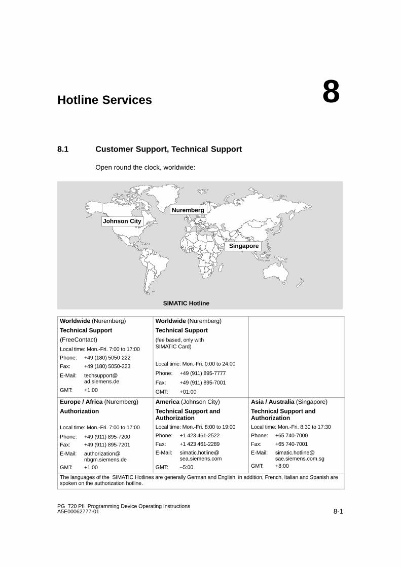
8-1PG 720 PII Programming Device Operating InstructionsA5E00062777-01
Hotline Services
8.1 Customer Support, Technical Support
Open round the clock, worldwide:
Johnson City
Nuremberg
Singapore
SIMATIC Hotline
Worldwide (Nuremberg)
Technical Support
(FreeContact)
Local time: Mon.-Fri. 7:00 to 17:00
Phone: +49 (180) 5050-222
Fax: +49 (180) 5050-223
E-Mail: [email protected]
GMT: +1:00
Worldwide (Nuremberg)
Technical Support
(fee based, only with SIMATIC Card)
Local time: Mon.-Fri. 0:00 to 24:00
Phone: +49 (911) 895-7777
Fax: +49 (911) 895-7001
GMT: +01:00
Europe / Africa (Nuremberg)
Authorization
Local time: Mon.-Fri. 7:00 to 17:00
Phone: +49 (911) 895-7200
Fax: +49 (911) 895-7201
E-Mail: [email protected]
GMT: +1:00
America (Johnson City)
Technical Support andAuthorizationLocal time: Mon.-Fri. 8:00 to 19:00
Phone: +1 423 461-2522
Fax: +1 423 461-2289
E-Mail: [email protected]
GMT: –5:00
Asia / Australia (Singapore)
Technical Support andAuthorizationLocal time: Mon.-Fri. 8:30 to 17:30
Phone: +65 740-7000
Fax: +65 740-7001
E-Mail: [email protected]
GMT: +8:00
The languages of the SIMATIC Hotlines are generally German and English, in addition, French, Italian and Spanish arespoken on the authorization hotline.
8

Hotline Services
8-2PG 720 PII Programming Device Operating Instructions
A5E00062777-01
8.2 SIMATIC Customer Support Online Services
The SIMATIC Customer Support team offers you substantial additional informationabout SIMATIC products via its online services:
� General current information can be obtained from:
– the Internet under http://www.ad.siemens.de/simatic
� Current product information leaflets and downloads which you may find usefulare available:
– the Internet under http://www.ad.siemens.de/simatic-cs
– via the Bulletin Board System (BBS) in Nuremberg (SIMATIC CustomerSupport Mailbox) under the number +49 (911) 895-7100.
To access the mailbox, use a modem with up to V.34 (28.8 Kbps) withparameters set as follows: 8, N, 1, ANSI; or dial in via ISDN (x.75, 64 Kbps).
� You can find your local customer service representative for Automation & Drivesin our customer service representative data bank:
– in the Internet under http://www3.ad.siemens.de/partner/search.asp?lang=en

Hotline Services
8-3PG 720 PII Programming Device Operating InstructionsA5E00062777-01
8.3 Regional Repair Centers
Region Phone Fax
Augsburg +49 (821)2595 599 +49 (821)2595 546
Berlin +49 (30)386 34926 +49 (30)386 34933
Bielefeld +49 (521)291 323 +49 (521)291 538
Bremen +49 (421)364 2093 +49 (421)364 2107
Chemnitz +49 (371)475 3860 +49 (371)475 3888
Erlangen +49 (9131)7 31048 +49 (9131)7 35263
Essen +49 (201)816 1580 +49 (201)816 1522
Frankfurt +49 (69)797 7358 +49 (69)797 7131
Hamburg +49 (40)2889 4230 +49 (40)2889 4430
Hannover-Laatzen +49 (511)877 2241 +49 (511)877 1320
Karlsruhe +49 (721)595 4183 +49 (721)595 6667
Cologne-Ossendorf +49 (221)576 6633 +49 (221)576 6630
Langen +49 (69)797 5608 +49 (69)797 5567
Leipzig +49 (341)210 2049 +49 (341)210 2049
Mannheim +49 (621)456 1328 +49 (621)456 1460
Munich +49 (89)9221 6213 +49 (89)9221 6201
Nuremberg +49 (911)654 6127 +49 (911)654 7630
Saarbrücken +49 (681)386 2598 +49 (681)386 2397
Stuttgart Weilimdorf +49 (711)137 6001 +49 (711)137 6210

Hotline Services
8-4PG 720 PII Programming Device Operating Instructions
A5E00062777-01
Country Phone Fax
Argentina +54 (1) 3408400 +54 (1) 3408400 3163
Australia +61 (3) 9420 7274 +54 (3) 9420 7500
Belgium +32 (2) 536 2905 +32 (2) 536 2880
Brazil +55 (11) 7947 1999 ext.3013
+55 (11) 7947 1888
China +86 (21) 6213 2050 ext.301
+86 (21) 6213 5538
Denmark +45 (7640) 5151 +45 (7640) 5143
Finland +358 (9) 5105 3303 +358 (9) 5105 3661
France +33 (1) 49 22 31 60 +33 (1) 49 22 29 42
Great Britain +44 (161) 446 5760 +44 (161) 446 5772
India +91 22 7577115 +91 22 7577106
Italy +39 (02) 6676 3490
Japan +81 (3) 5423 8502 +81 (3) 5423 8737
Mexico +52 (5) 328 2456 +52 (5) 328 2058
Netherlands +31 (70) 333 3858 +31 (70) 333 3878
Austria +43 (1) 1707 29886 +43 (1) 1707 53730
Poland +48 (22) 670 9166 +48 (22) 670 9169
Portugal +351 (1) 75 73234 +351 (1) 75 89333
Schweden +46 (8) 728 1462 +46 (8) 728 1703
Switzerland +41 (1) 749 1304 +41 (1) 749 1284
Singapur +65 (740) 7150 +65 (740) 7196
Spain +34 (91) 514 8400 +34 (91) 514 9217
South Africa +27 (12) 309 0149 +27 (12) 309 0142
South Korea +82 (2) 3420 4880 +82 (2) 3420 4889
Taiwan +886 (2) 2376 1849 +886 (2) 2378 8958
Thailand +66 (2) 716 4609 +66 (2) 716 4601
USA +1 (423) 461 2497 +1 (423) 461 2094
Note
In countries not listed above, please contact your local service representative. Hewill arrange for your repairs to be carried out.

![Smart IP Wall PAD Solution [호환 모드] - AddPac • Firmware Upgradeable ArchitectureFirmware Upgradeable Architecture • Smart Multimedia Manager for IP-PBX Management • DACM(Door](https://static.fdocuments.net/doc/165x107/5dd098fad6be591ccb61c3e1/smart-ip-wall-pad-solution-eeoe-a-firmware-upgradeable-architecturefirmware.jpg)