Pfr 15 1mt Book
288
Performance Routing Configuration Guide, Cisco IOS Release 15.1MT Americas Headquarters Cisco Systems, Inc. 170 West Tasman Drive San Jose, CA 95134-1706 USA http://www.cisco.com Tel: 408 526-4000 800 553-NETS (6387) Fax: 408 527-0883
-
Upload
osneider-perez-torrado -
Category
Documents
-
view
52 -
download
7
Transcript of Pfr 15 1mt Book

Performance Routing ConfigurationGuide, Cisco IOS Release 15.1MT
Americas HeadquartersCisco Systems, Inc.170 West Tasman DriveSan Jose, CA 95134-1706USAhttp://www.cisco.comTel: 408 526-4000 800 553-NETS (6387)Fax: 408 527-0883

THE SPECIFICATIONS AND INFORMATION REGARDING THE PRODUCTS IN THIS MANUAL ARE SUBJECT TO CHANGE WITHOUT NOTICE. ALL STATEMENTS,INFORMATION, AND RECOMMENDATIONS IN THIS MANUAL ARE BELIEVED TO BE ACCURATE BUT ARE PRESENTED WITHOUT WARRANTY OF ANY KIND,EXPRESS OR IMPLIED. USERS MUST TAKE FULL RESPONSIBILITY FOR THEIR APPLICATION OF ANY PRODUCTS.
THE SOFTWARE LICENSE AND LIMITED WARRANTY FOR THE ACCOMPANYING PRODUCT ARE SET FORTH IN THE INFORMATION PACKET THAT SHIPPEDWITH THE PRODUCT AND ARE INCORPORATED HEREIN BY THIS REFERENCE. IF YOU ARE UNABLE TO LOCATE THE SOFTWARE LICENSE OR LIMITEDWARRANTY, CONTACT YOUR CISCO REPRESENTATIVE FOR A COPY.
The Cisco implementation of TCP header compression is an adaptation of a program developed by the University of California, Berkeley (UCB) as part of UCB’s public domain versionof the UNIX operating system. All rights reserved. Copyright © 1981, Regents of the University of California.
NOTWITHSTANDING ANY OTHER WARRANTY HEREIN, ALL DOCUMENT FILES AND SOFTWARE OF THESE SUPPLIERS ARE PROVIDED “AS IS” WITH ALLFAULTS. CISCO AND THE ABOVE-NAMED SUPPLIERS DISCLAIM ALL WARRANTIES, EXPRESSED OR IMPLIED, INCLUDING, WITHOUT LIMITATION, THOSE OFMERCHANTABILITY, FITNESS FOR A PARTICULAR PURPOSE AND NONINFRINGEMENT OR ARISING FROM A COURSE OF DEALING, USAGE, OR TRADEPRACTICE.
IN NO EVENT SHALL CISCO OR ITS SUPPLIERS BE LIABLE FOR ANY INDIRECT, SPECIAL, CONSEQUENTIAL, OR INCIDENTAL DAMAGES, INCLUDING,WITHOUT LIMITATION, LOST PROFITS OR LOSS OR DAMAGE TO DATA ARISING OUT OF THE USE OR INABILITY TO USE THIS MANUAL, EVEN IF CISCO ORITS SUPPLIERS HAVE BEEN ADVISED OF THE POSSIBILITY OF SUCH DAMAGES.
Cisco and the Cisco Logo are trademarks of Cisco Systems, Inc. and/or its affiliates in the U.S. and other countries. A listing of Cisco's trademarks can be found at www.cisco.com/go/trademarks. Third party trademarks mentioned are the property of their respective owners. The use of the word partner does not imply a partnership relationship between Cisco and anyother company. (1005R)
Any Internet Protocol (IP) addresses and phone numbers used in this document are not intended to be actual addresses and phone numbers. Any examples, command display output,network topology diagrams, and other figures included in the document are shown for illustrative purposes only. Any use of actual IP addresses or phone numbers in illustrative contentis unintentional and coincidental.
© 2011 Cisco Systems, Inc. All rights reserved.

C O N T E N T S
Configuring Basic Performance Routing 1
Finding Feature Information 1
Information About Configuring Basic Performance Routing 2
Performance Routing Overview 2
Performance Routing Versus Optimized Edge Routing 2
Migration from Optimized Edge Routing to Performance Routing 3
Performance Routing Versus Classic Routing Technologies 3
Basic Performance Routing Deployment 3
PfR Border Router 4
PfR Master Controller 4
PfR Component Version 4
Key Chain Authentication for PfR 4
PfR-Managed Network Interfaces 5
PfR Network Performance Loop 6
Profile Phase 7
Measure Phase 7
Apply Policy Phase 8
Enforce Phase 8
Verify Phase 8
PfR and the Enterprise Network 9
Typical Topology on Which PfR is Deployed 9
How to Configure Basic Performance Routing 10
Setting Up the PfR Master Controller 10
Setting Up a PFR Border Router 15
What to Do Next 18
Configuration Examples for Configuring Basic Performance Routing 18
Example Configuring the PfR Master Controller 19
Example Configuring a PfR Border Router 19
Where to Go Next 19
Performance Routing Configuration Guide, Cisco IOS Release 15.1MT iii

Additional References 20
Feature Information for Configuring Basic Performance Routing 20
Understanding Performance Routing 23
Finding Feature Information 23
Prerequisites for Understanding Performance Routing 23
Information About Understanding Performance Routing 24
Profile Phase Concepts 24
Traffic Class Profiling Overview 24
Automatic Traffic Class Learning 25
Prefix Traffic Class Learning Using PfR 25
Application Traffic Class Learning Using PfR 26
Learn List Configuration Mode 26
Manual Traffic Class Configuration 27
Prefix Traffic Class Configuration Using PfR 27
Application Traffic Class Configuration Using PfR 28
Measure Phase Concepts 28
Traffic Class Performance Measurement Overview 29
Traffic Class Performance Measurement Techniques 30
Passive Monitoring 31
Active Monitoring 32
Combined Monitoring 34
Fast Failover Monitoring 34
Special Monitoring 35
Link Utilization Measurement Techniques 35
Apply Policy Phase Concepts 36
Apply Policy Phase Overview 36
PfR Policy Decision Point 37
Traffic Class Performance Policies 38
PfR Link Policies 40
PfR Link Grouping 41
PfR Network Security Policies 42
PfR Policy Operational Options and Parameters 42
PfR Timers Parameters 42
PfR Mode Options 43
PfR Policy Application 44
Contents
Performance Routing Configuration Guide, Cisco IOS Release 15.1MTiv

Priority Resolution for Multiple PfR Policies 44
Enforce Phase Concepts 45
PfR Enforce Phase Overview 45
PfR Traffic Class Control Techniques 46
PfR Exit Link Selection Control Techniques 47
PfR Entrance Link Selection Control Techniques 49
Verify Phase Concepts 49
Verify Phase Overview 49
Where To Go Next 50
Additional References 50
Feature Information for Understanding Performance Routing 51
Configuring Advanced Performance Routing 57
Finding Feature Information 57
Prerequisites for Configuring Advanced Performance Routing 57
Information About Advanced Performance Routing 58
Performance Routing Overview 58
Advanced Performance Routing Deployment 59
Profile Phase 59
Measure Phase 59
Apply Policy Phase 60
Enforce Phase 60
Verify Phase 60
PfR Active Probing Target Reachability 61
ICMP Echo Probes 61
Jitter 61
MOS 61
How to Configure Advanced Performance Routing 61
Profiling Phase Tasks 62
Defining a Learn List for Automatically Learned Application Traffic Classes Using an
Access List 62
Manually Selecting Prefix-Based Traffic Classes Using a Prefix List 66
Displaying and Resetting Traffic Class and Learn List Information 68
Measuring Phase Tasks 70
Modifying the PfR Link Utilization for Outbound Traffic 70
Modifying the PfR Exit Link Utilization Range 72
Contents
Performance Routing Configuration Guide, Cisco IOS Release 15.1MT v

Configuring and Verifying PfR Passive Monitoring 73
Configuring PfR Active Probing Using the Longest Match Target Assignment 75
Configuring PfR Voice Probes with a Forced Target Assignment 77
Configuring PfR Voice Probes for Fast Failover 81
Configuring the Source Address of an Active Probe 86
Apply Policy Phase Tasks 88
Configuring and Applying a PfR Policy to Learned Traffic Classes 88
Preventing PfR Optimization of Learned Prefixes 92
Configuring Policy Rules for PfR Maps 94
Configuring Multiple PfR Policy Conflict Resolution 95
Configuring Black Hole Routing Using a PfR Map 97
Configuring Sinkhole Routing Using a PfR Map 99
Enforce Phase Tasks 101
Controlling Application Traffic 101
Verify Phase Task 104
Manually Verifying the PfR Route Enforce Changes 104
Configuration Examples for Advanced Performance Routing 106
Profile Phase Tasks Examples 106
Example Defining a Learn List for Automatically Learned Prefix-Based Traffic Classes 106
Example Defining a Learn List for Automatically Learned Application Traffic Classes
Using an Access List 107
Example Manually Selecting Prefix-Based Traffic Classes Using a Prefix List 107
Example Manually Selecting Application Traffic Classes Using an Access List 107
Measure Phase Tasks Examples 108
Example Modifying the PfR Link Utilization for Outbound Traffic 108
Example Modifying the PfR Exit Link Utilization Range 108
Example TCP Probe for Longest Match Target Assignment 108
UDP Probe for Forced Target Assignment Example 109
Example Configuring PfR Voice Probes for Fast Failover 109
Example Configuring the Source Address of an Active Probe 111
Apply Policy Phase Tasks Examples 111
Example Configuring and Applying a PfR Policy to Learned Traffic Classes 112
Example Configuring and Applying a PfR Policy to Configured Traffic Classes 112
Example Preventing PfR Optimization of Learned Prefixes 112
Example Configuring Policy Rules for PfR Maps 113
Contents
Performance Routing Configuration Guide, Cisco IOS Release 15.1MTvi

Example Configuring Multiple PfR Policy Conflict Resolution 113
Example Configuring an Exit Link Load Balancing PfR Policy 113
Example Configuring Black Hole Routing Using a PfR Map 114
Example Configuring Sinkhole Routing Using a PfR Map 114
Enforce Phase Tasks Examples 114
Example Setting a Tag Value for Injected PfR Static Routes 114
Example Setting a BGP Local Preference Value for PfR Controlled BGP Routes 114
Example Controlling Application Traffic 115
Verify Phase Task Example 115
Example Manually Verifying the PfR Route Control Changes 115
Where to Go Next 116
Additional References 116
Feature Information for Configuring Advanced Performance Routing 117
BGP Inbound Optimization Using Performance Routing 121
Finding Feature Information 121
Information About BGP Inbound Optimization Using Performance Routing 121
BGP Inbound Optimization 122
Prefix Traffic Class Learning Using PfR 122
PfR Link Utilization Measurement 122
PfR Link Policies 123
PfR Entrance Link Selection Control Techniques 124
PfR Map Operation for Inside Prefixes 125
How to Configure BGP Inbound Optimization Using Performance Routing 125
Configuring PfR to Automatically Learn Traffic Classes Using Inside Prefixes 125
Manually Selecting Inside Prefixes for PfR Monitoring 128
Modifying the PfR Link Utilization for Inbound Traffic 129
Modifying the PfR Entrance Link Utilization Range 131
Configuring and Applying a PfR Policy to Learned Inside Prefixes 132
Configuring and Applying a PfR Policy to Configured Inside Prefixes 135
Configuration Examples for BGP Inbound Optimization Using Performance Routing 137
Example Configuring PfR to Automatically Learn Traffic Classes Using Inside Prefixes 137
Example Manually Selecting Inside Prefixes for PfR Monitoring 138
Example Modifying the PfR Link Utilization for Inbound Traffic 138
Example Modifying the PfR Entrance Link Utilization Range 138
Example Configuring and Applying a PfR Policy to Learned Inside Prefixes 138
Contents
Performance Routing Configuration Guide, Cisco IOS Release 15.1MT vii

Example Configuring and Applying a PfR Policy to Configured Inside Prefixes 139
Additional References 139
Feature Information for BGP Inbound Optimization Using Performance Routing 140
Configuring Performance Routing Cost Policies 143
Finding Feature Information 143
Prerequisites for Performance Routing Cost Policies 143
Information About Performance Routing Cost Policies 143
Overview of PfR Link Policies 144
Traffic Load (Utilization) Policy 144
Range Policy 144
Cost Policy 145
Cost Policy Billing Models 145
Link Utilization Rollup Calculations 145
Monthly Sustained Utilization Calculation 146
How to Configure Performance Routing Cost Policies 148
Configuring a Basic PfR Cost-Based Policy 148
Using a PfR Cost Policy to Minimize Billing and Load Balance Traffic 153
Verifying and Debugging PfR Cost-Minimization Policies 161
Configuration Examples for Performance Routing Cost Policies 163
Example Configuring a Basic PfR Cost-Based Policy 163
Example Using a PfR Cost Policy to Minimize Billing and Load Balance Traffic 164
Where to Go Next 166
Additional References 166
Feature Information for Configuring Performance Routing Cost Policies 167
Using Performance Routing to Control EIGRP Routes with mGRE DMVPN Hub-and-
Spoke Support 169
Finding Feature Information 169
Prerequisites for Using PfR to Control EIGRP Routes 169
Restrictions for Using PfR to Control EIGRP Routes 170
Information About Using PfR to Control EIGRP Routes 170
PfR EIGRP Route Control 170
PfR and mGRE Dynamic Multipoint VPN 171
How to Configure PfR to Control EIGRP Routes 173
Enabling PfR EIGRP Route Control and Setting a Community Value 173
Disabling PfR EIGRP Route Control 174
Contents
Performance Routing Configuration Guide, Cisco IOS Release 15.1MTviii

Manually Verifying the PfR EIGRP-Controlled Routes 175
Troubleshooting Tips 177
Configuration Examples for Using PfR to Control EIGRP Routes 177
Example Enabling PfR EIGRP Route Control and Setting a Community Value 178
Where to Go Next 178
Additional References 178
Feature Information for Using PfR to Control EIGRP Routes 179
Performance Routing Link Groups 181
Finding Feature Information 181
Information About Performance Routing Link Groups 181
Performance Routing Link Grouping 181
How to Configure Performance Routing Link Groups 183
Implementing Performance Routing Link Groups 183
Configuration Examples for Performance Routing Link Groups 188
Example Implementing Performance Routing Link Groups 188
Where to Go Next 188
Additional References 188
Feature Information for Performance Routing Link Groups 189
Performance Routing with NAT 191
Finding Feature Information 191
Restrictions for Performance Routing with NAT 191
Information About Performance Routing with NAT 192
PfR and NAT 192
Network Address Translation (NAT) 193
Inside Global Addresses Overloading 193
How to Configure Performance Routing with NAT 193
Configuring PfR to Control Traffic with Static Routing in Networks Using NAT 193
Configuration Examples for Performance Routing with NAT 197
Example Configuring PfR to Control Traffic with Static Routing in Networks Using NAT 197
Where to Go Next 198
Additional References 198
Feature Information for Performance Routing with NAT 199
Performance Routing with NBAR CCE Application Recognition 201
Finding Feature Information 201
Prerequisites for PfR with NBAR CCE Application Recognition 201
Contents
Performance Routing Configuration Guide, Cisco IOS Release 15.1MT ix

Information About PfR with NBAR CCE Application Recognition 202
Performance Routing Traffic Class Profiling 202
PfR Application Mapping Using NBAR 203
How to Configure PfR with NBAR CCE Application Recognition 206
Defining a Learn List to Automatically Learn Traffic Classes Using NBAR Application
Mapping 206
Manually Selecting Traffic Classes Using NBAR Application Mapping 210
Displaying and Resetting Information About Traffic Classes Identified Using NBAR 212
Configuration Examples for PfR with NBAR CCE Application Recognition 215
Example Defining a Learn List to Automatically Learn Traffic Classes Using NBAR
Application Mapping 216
Example Manually Selecting Traffic Classes Using NBAR Application Mapping 216
Where To Go Next 217
Additional References 217
Feature Information for PfR with NBAR CCE Application Recognition 218
Performance Routing - Protocol Independent Route Optimization (PIRO) 221
Finding Feature Information 221
Information About Performance Routing PIRO 221
Protocol Independent Route Optimization (PIRO) 221
How to Configure Performance Routing PIRO 222
Verifying and Debugging Protocol Independent Route Optimization Route Control Changes 222
Where to Go Next 225
Additional References 225
Feature Information for Performance Routing PIRO 226
Static Application Mapping Using Performance Routing 229
Finding Feature Information 229
Prerequisites for Static Application Mapping Using Performance Routing 229
Information About Static Application Mapping Using Performance Routing 230
Performance Routing Traffic Class Profiling 230
Static Application Mapping Using PfR 231
Learn List Configuration Mode 233
How to Configure Static Application Mapping Using Performance Routing 234
Defining a Learn List to Automatically Learn Traffic Classes Using Static Application
Mapping 234
Manually Selecting Traffic Classes Using Static Application Mapping 239
Displaying and Resetting Traffic Class and Learn List Information 240
Contents
Performance Routing Configuration Guide, Cisco IOS Release 15.1MTx

Configuration Examples for Static Application Mapping Using Performance Routing 242
Example Defining a Learn List to Automatically Learn Traffic Classes Using Static
Application Mapping 242
Example Defining a Learn List for Automatically Learned Prefix-Based Traffic Classes 243
Example Defining a Learn List for Automatically Learned Application Traffic Classes Using
an Access List 243
Example Manually Selecting Traffic Classes Using Static Application Mapping 244
Example Manually Selecting Prefix-Based Traffic Classes Using a Prefix List 244
Example Manually Selecting Application Traffic Classes Using an Access List 245
Where To Go Next 245
Additional References 245
Feature Information for Static Application Mapping Using Performance Routing 246
Performance Routing Traceroute Reporting 249
Finding Feature Information 249
Information About Performance Routing Traceroute Reporting 249
PfR Logging and Reporting 249
PfR Troubleshooting Using Traceroute Reporting 250
How to Configure Performance Routing Traceroute Reporting 250
Configuring PfR Traceroute Reporting 251
Configuration Examples for Performance Routing Traceroute Reporting 253
Example Configuring PfR Traceroute Reporting 253
Where to Go Next 254
Additional References 254
Feature Information for Performance Routing Traceroute Reporting 255
PfR Voice Traffic Optimization Using Active Probes 257
Finding Feature Information 257
Prerequisites for PfR Voice Traffic Optimization Using Active Probes 257
Information About PfR Voice Traffic Optimization Using Active Probes 258
Voice Quality on IP Networks 258
Probes Used by PfR 259
PfR Voice Traffic Optimization Using Active Probes 259
PfR Voice Performance Metrics 260
PfR Active Probe Forced Target Assignment 260
How to Configure PfR Voice Traffic Optimization Using Active Probes 261
Identifying Traffic for PfR Using a Prefix List 261
Identifying Voice Traffic to Optimize Using an Access List 262
Contents
Performance Routing Configuration Guide, Cisco IOS Release 15.1MT xi

Identifying Voice Traffic to Optimize Using an Access List 263
Configuring PfR Voice Probes with a Target Assignment 264
Configuration Examples for PfR Voice Traffic Optimization Using Active Probes 270
Example Optimizing Only Voice Traffic Using Active Probes 271
Example Optimizing Traffic (Including Voice Traffic) Using Active Probes 272
Where to Go Next 273
Additional References 273
Feature Information for PfR Voice Traffic Optimization Using Active Probes 274
Contents
Performance Routing Configuration Guide, Cisco IOS Release 15.1MTxii

Configuring Basic Performance Routing
Performance Routing (PfR) provides additional intelligence to classic routing technologies to track theperformance of, or verify the quality of, a path between two devices over a Wide Area Networking(WAN) infrastructure to determine the best egress or ingress path for application traffic.
Cisco Performance Routing complements classic IP routing technologies by adding intelligence to selectbest paths to meet application performance requirements. The first phase of Performance Routingtechnology intelligently optimizes application performance over enterprise WANs and to and from theInternet. This technology will evolve to help enable application performance optimization throughout theenterprise network through an end-to-end, performance-aware network.
This document contains an introduction to the basic concepts and tasks required to implementPerformance Routing. For more detailed concepts, see the Understanding Performance Routing module,and for more advanced concepts and configuration tasks and examples, see the Configuring AdvancedPerformance Routing module.
Note The PfR configuration modules refer to the PfR syntax introduced in Cisco IOS Release 15.1(2)T. If youare running Cisco IOS Release 15.1(1)T, or an earlier release, or any 12.2SR or 12.2SX image, you needto consult the Cisco IOS Optimized Edge Routing Overview module to help you locate all the OptimizedEdge Routing documentation.
• Finding Feature Information, page 1• Information About Configuring Basic Performance Routing, page 2• How to Configure Basic Performance Routing, page 10• Configuration Examples for Configuring Basic Performance Routing, page 18• Where to Go Next, page 19• Additional References, page 20• Feature Information for Configuring Basic Performance Routing, page 20
Finding Feature InformationYour software release may not support all the features documented in this module. For the latest featureinformation and caveats, see the release notes for your platform and software release. To find informationabout the features documented in this module, and to see a list of the releases in which each feature issupported, see the Feature Information Table at the end of this document.
Use Cisco Feature Navigator to find information about platform support and Cisco software image support.To access Cisco Feature Navigator, go to www.cisco.com/go/cfn. An account on Cisco.com is not required.
Performance Routing Configuration Guide, Cisco IOS Release 15.1MT 1

Information About Configuring Basic Performance Routing• Performance Routing Overview, page 2
• Performance Routing Versus Optimized Edge Routing, page 2
• Migration from Optimized Edge Routing to Performance Routing, page 3
• Performance Routing Versus Classic Routing Technologies, page 3
• Basic Performance Routing Deployment, page 3
• PfR Border Router, page 4
• PfR Master Controller, page 4
• PfR Component Version, page 4
• Key Chain Authentication for PfR, page 4
• PfR-Managed Network Interfaces, page 5
• PfR Network Performance Loop, page 6
• PfR and the Enterprise Network, page 9
Performance Routing OverviewPerformance Routing (PfR) is an advanced Cisco technology to allow businesses to complement classicrouting technologies with additional serviceability parameters to select the best egress or ingress path. Itcomplements these classic routing technologies with additional intelligence. PfR can select an egress oringress WAN interface based upon parameters like reachability, delay, cost, jitter, MOS score, or it can useinterface parameters like load, throughput and monetary cost. Classic routing (for example, EIGRP, OSPF,RIPv2, and BGP) generally focuses upon creating a loop-free topology based upon the shortest or least costpath.
PfR gains additional intelligence using measurement instrumentation. It uses interface statistics, Cisco IPSLA for active monitoring, and NetFlow for passive monitoring. No prior knowledge or experience of IPSLA or NetFlow is required, PfR automatically enables these technologies without any manualconfiguration.
Cisco Performance Routing selects an egress or ingress WAN path based on parameters that affectapplication performance, including reachability, delay, cost, jitter, and Mean Opinion Score (MOS). Thistechnology can reduce network costs by facilitating more efficient load balancing and by increasingapplication performance without WAN upgrades.
PfR is an integrated Cisco IOS solution that allows you to monitor IP traffic flows and then define policiesand rules based on traffic class performance, link load distribution, link bandwidth monetary cost, andtraffic type. PfR provides active and passive monitoring systems, dynamic failure detection, and automaticpath correction. Deploying PfR enables intelligent load distribution and optimal route selection in anenterprise network.
Performance Routing Versus Optimized Edge RoutingCisco Performance Routing takes advantage of the vast intelligence embedded in Cisco IOS Software todetermine the optimal path based upon network and application policies. Cisco Performance Routing is anevolution of the Cisco IOS Optimized Edge Routing (OER) technology with a much broader scope. OERwas originally designed to provide route control on a per destination prefix basis, but Performance Routinghas expanded capabilities that facilitate intelligent route control on a per application basis. The expandedcapabilities provide additional flexibility and more granular application optimization than OER.
Performance Routing Overview Information About Configuring Basic Performance Routing
Performance Routing Configuration Guide, Cisco IOS Release 15.1MT2

Migration from Optimized Edge Routing to Performance RoutingIf you are migrating to Performance Routing from an implementation of Optimized Edge Routing in anearlier Cisco IOS Release image, you must be aware of the following information to ensure a smoothmigration path. In Cisco IOS Release 15.1(2)T, the OER syntax is still recognized. When you enter OERsyntax the software changes the syntax to the new PfR syntax in the running configuration. When therunning configuration is saved, the PfR version of the syntax is saved. If you need to reload an older CiscoIOS image, we recommend that you save backup copies of all configuration scripts with the OER syntaxversion because the new PfR syntax will not run in an older Cisco IOS software image.
Performance Routing Versus Classic Routing TechnologiesPfR was developed to identify and control network performance issues that traditional IP routing cannotaddress. In traditional IP routing, each peer device communicates its view of reachability to a prefixdestination with some concept of a cost related to reaching the metric. The best path route to a prefixdestination is usually determined using the least cost metric, and this route is entered into the routinginformation base (RIB) for the device. As a result, any route introduced into the RIB is treated as the bestpath to control traffic destined for the prefix destination. The cost metric is configured to reflect a staticallyengineered view of the network, for example, the cost metric is a reflection of either a user preference for apath or a preference for a higher bandwidth interface (inferred from the type of interface). The cost metricdoes not reflect the state of the network or the state of the performance of traffic traveling on that networkat that time. Traditional IP routed networks are therefore adaptive to physical state changes in the network(for example, interfaces going down) but not to performance changes (degradation or improvement) in thenetwork. Occasionally, degradation in traffic can be inferred from either the degradation in performance ofthe routing device or the loss of session connectivity, but these traffic degradation symptoms are not adirect measure of the performance of the traffic and cannot be used to influence decisions about best-pathrouting.
To address performance issues for traffic within a network, PfR manages traffic classes. Traffic classes aredefined as subsets of the traffic on the network, and a subset may represent the traffic associated with anapplication, for example. The performance of each traffic class is measured and compared againstconfigured or default metrics defined in an PfR policy. PfR monitors the traffic class performance andselects the best entrance or exit for the traffic class. If the subsequent traffic class performance does notconform to the policy, PfR selects another entrance or exit for the traffic class.
Basic Performance Routing DeploymentPfR is configured on Cisco routers using Cisco IOS command-line interface (CLI) configurations.Performance Routing comprises two components: the Master Controller (MC) and the Border Router (BR).A PfR deployment requires one MC and one or more BRs. Communication between the MC and the BR isprotected by key-chain authentication. Depending on your Performance Routing deployment scenario andscaling requirements, the MC may be deployed on a dedicated router or may be deployed along with theBR on the same physical router.
A PfR-managed network must have at least two egress interfaces that can carry outbound traffic and can beconfigured as external interfaces, see the figure below. These interfaces should connect to an ISP or WANlink (Frame-Relay, ATM) at the network edge. The router must also have one interface (reachable by theinternal network) that can be configured as an internal interface for passive monitoring. There are threeinterface configurations required to deploy PfR: external interfaces, internal interfaces, and local interfaces.
Migration from Optimized Edge Routing to Performance RoutingInformation About Configuring Basic Performance Routing
Performance Routing Configuration Guide, Cisco IOS Release 15.1MT 3

PfR Border RouterThe BR component resides within the data plane of the edge router with one or more exit links to an ISP orother participating network.The BR uses NetFlow to passively gather throughput and TCP performanceinformation. The BR also sources all IP service-level agreement (SLA) probes used for explicit applicationperformance monitoring. The BR is where all policy decisions and changes to routing in the network areenforced. The BR participates in prefix monitoring and route optimization by reporting prefix and exit linkmeasurements to the master controller and then by enforcing policy changes received from the mastercontroller. The BR enforces policy changes by injecting a preferred route to alter routing in the network. ABR process can be enabled on the same router as a master controller process.
PfR Master ControllerThe MC is a single router that acts as the central processor and database for the Performance Routingsystem. The MC component does not reside in the forwarding plane and, when deployed in a standalonefashion, has no view of routing information contained within the BR. The master controller maintainscommunication and authenticates the sessions with the BRs. The role of the MC is to gather informationfrom the BR or BRs to determine whether or not traffic classes are in or out of policy, and to instruct theBRs how to ensure that traffic classes remain in policy using route injection or dynamic PBR injection.
PfR Component VersionWhen new PfR functionality is introduced that changes the API between the MC and the BR, the versionnumber for the Performance Routing components, master controller and border router, is incremented. Theversion number of the master controller must be equal or higher to the version number for the borderrouters.The version numbers for both the master controller and the border routers are displayed using theshow pfr master command. In the following partial output, the MC version is shown in the first paragraphand the BR versions are shown in the last column of the information for the border routers.
Router# show pfr masterOER state: ENABLED and ACTIVE Conn Status: SUCCESS, PORT: 7777 Version: 2.0 Number of Border routers: 2 Number of Exits: 2...Border Status UP/DOWN AuthFail Version1.1.1.2 ACTIVE UP 00:18:57 0 2.01.1.1.1 ACTIVE UP 00:18:58 0 2.0...
The version numbers are not updated at each Cisco IOS software release for a specific release train, but ifthe Cisco IOS software image is the same release on the devices configured as a master controller and allthe border routers, then the versions will be compatible.
Key Chain Authentication for PfRCommunication between the master controller and the border router is protected by key-chainauthentication. The authentication key must be configured on both the master controller and the borderrouter before communication can be established. The key-chain configuration is defined in globalconfiguration mode on both the master controller and the border router before key-chain authentication is
PfR Border Router Information About Configuring Basic Performance Routing
Performance Routing Configuration Guide, Cisco IOS Release 15.1MT4
enabled for master controller-to-border router communication. For more information about keymanagement, see the "Managing Authentication Keys" section of the Configuring IP Routing Protocol-Independent Features chapter in the Cisco IOS IP Routing: Protocol Independent Configuration Guide.
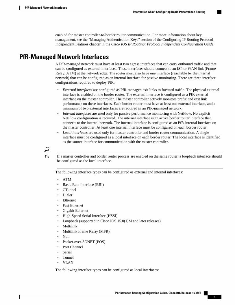
PfR-Managed Network InterfacesA PfR-managed network must have at least two egress interfaces that can carry outbound traffic and thatcan be configured as external interfaces. These interfaces should connect to an ISP or WAN link (Frame-Relay, ATM) at the network edge. The router must also have one interface (reachable by the internalnetwork) that can be configured as an internal interface for passive monitoring. There are three interfaceconfigurations required to deploy PfR:
• External interfaces are configured as PfR-managed exit links to forward traffic. The physical externalinterface is enabled on the border router. The external interface is configured as a PfR externalinterface on the master controller. The master controller actively monitors prefix and exit linkperformance on these interfaces. Each border router must have at least one external interface, and aminimum of two external interfaces are required in an PfR-managed network.
• Internal interfaces are used only for passive performance monitoring with NetFlow. No explicitNetFlow configuration is required. The internal interface is an active border router interface thatconnects to the internal network. The internal interface is configured as an PfR-internal interface onthe master controller. At least one internal interface must be configured on each border router.
• Local interfaces are used only for master controller and border router communication. A singleinterface must be configured as a local interface on each border router. The local interface is identifiedas the source interface for communication with the master controller.
Tip If a master controller and border router process are enabled on the same router, a loopback interface shouldbe configured as the local interface.
The following interface types can be configured as external and internal interfaces:
• ATM• Basic Rate Interface (BRI)• CTunnel• Dialer• Ethernet• Fast Ethernet• Gigabit Ethernet• High-Speed Serial Interface (HSSI)• Loopback (supported in Cisco IOS 15.0(1)M and later releases)• Multilink• Multilink Frame Relay (MFR)• Null• Packet-over-SONET (POS)• Port Channel• Serial• Tunnel• VLAN
The following interface types can be configured as local interfaces:
PfR-Managed Network InterfacesInformation About Configuring Basic Performance Routing
Performance Routing Configuration Guide, Cisco IOS Release 15.1MT 5

• Async• Bridge Group Virtual Interface (BVI)• Code division multiple access Internet exchange (CDMA-Ix)• CTunnel• Dialer• Ethernet• Group-Async• Loopback• Multilink• Multilink Frame Relay (MFR)• Null• Serial• Tunnel• Virtual host interface (Vif)• Virtual-PPP• Virtual-Template• Virtual-TokenRing
Note A virtual-TokenRing interface can be configured as a local interface. However, Token Ring interfaces arenot supported and cannot be configured as external, internal, or local interfaces.
Note PfR does not support Ethernet interfaces that are Layer 2 only, for example, Ethernet switched interfaces.
Performance Routing DMVPN mGre Support
• PfR does not support split tunneling.• PfR supports hub-to-spoke links only. Spoke-to-spoke links are not supported.• PfR is supported on DMVPN Multipoint GRE (mGRE) deployments. Any multipoint interface
deployment that has multiple next hops for the same destination IP address is not supported (forexample, Ethernet).
PfR Network Performance LoopEvery traditional routing protocol creates a feedback loop among devices to create a routing topology.Performance Routing infrastructure includes a performance routing protocol that is communicated in aclient-server messaging mode. The routing protocol employed by PfR runs between a network controllercalled a master controller and performance-aware devices called border routers. This performance routingprotocol creates a network performance loop in which the network profiles which traffic classes have to beoptimized, measures and monitors the performance metrics of the identified traffic classes, applies policies
PfR Network Performance Loop Information About Configuring Basic Performance Routing
Performance Routing Configuration Guide, Cisco IOS Release 15.1MT6

to the traffic classes, and routes the identified traffic classes based on the best performance path. Thediagram below shows the five PfR phases: profile, measure, apply policy, enforce, and verify.
Figure 1 PfR Network Performance Loop
To understand how PfR operates in a network, you should understand and implement the five PfR phases.The PfR performance loop starts with the profile phase followed by the measure, apply policy, control, andverify phases. The flow continues after the verify phase back to the profile phase to update the trafficclasses and cycle through the process.
• Profile Phase, page 7• Measure Phase, page 7• Apply Policy Phase, page 8• Enforce Phase, page 8• Verify Phase, page 8
Profile PhaseIn medium to large networks there are hundreds of thousands of routes in the RIB to which a device istrying to route traffic. Because performance routing is a means of preferring some traffic over another, asubset of the total routes in the RIB has to be selected to optimize for performance routing. PfR profilestraffic in one of two ways, automatic learning or manual configuration.
• Automatic Learning—The device profiles the traffic that has to be performance routed (optimized) bylearning the flows that pass through the device and by selecting those flows that have the highest delayor the highest throughput.
• Manual configuration—In addition to, or instead of learning, you can configure a class of traffic toperformance route.
Measure PhaseAfter profiling traffic classes that are to be performance routed, PfR measures the performance metrics ofthese individual traffic classes. There are two mechanisms--passive monitoring and active monitoring--tomeasure performance metrics, and one or both could be deployed in the network to accomplish this task.Monitoring is the act of measuring at periodic intervals.
Passive monitoring is the act of measuring the performance metrics of the traffic flow as the flow istraversing the device in the data path. Passive monitoring uses NetFlow functionality and cannot be
Configuring Basic Performance RoutingProfile Phase
Performance Routing Configuration Guide, Cisco IOS Release 15.1MT 7

employed for measuring performance metrics for some traffic classes, and there are some hardware orsoftware limitations.
Active monitoring consists of generating synthetic traffic using IP Service Level Agreements (SLAs) toemulate the traffic class that is being monitored. The synthetic traffic is measured instead of the actualtraffic class. The results of the synthetic traffic monitoring are applied to performance route the traffic classrepresented by the synthetic traffic.
Both passive and active monitoring modes can be applied to the traffic classes. The passive monitoringphase may detect traffic class performance that does not conform to an PfR policy, and then activemonitoring can be applied to that traffic class to find the best alternate performance path, if available.
Support for NetFlow or IP SLAs configuration is enabled automatically.
Apply Policy PhaseAfter collecting the performance metrics of the class of traffic to be optimized, PfR compares the resultswith a set of configured low and high thresholds for each metric configured as a policy. When a metric, andconsequently a policy, goes out of bounds, it is an Out-of-Policy (OOP) event. The results are compared ona relative basis--a deviation from the observed mean--or on a threshold basis--the lower or upper bounds ofa value--or a combination of both.
There are two types of policies that can be defined in PfR: traffic class policies and link policies. Trafficclass policies are defined for prefixes or for applications. Link policies are defined for exit or entrance linksat the network edge. Both types of PfR policies define the criteria for determining an OOP event. Thepolicies are applied on a global basis in which a set of policies is applied to all traffic classes, or on a moretargeted basis in which a set of policies is applied to a selected (filtered) list of traffic classes.
With multiple policies, many performance metric parameters, and different ways of assigning these policiesto traffic classes, a method of resolving policy conflicts was created. The default arbitration method uses adefault priority level given to each performance metric variable and each policy. Different priority levelscan be configured to override the default arbitration for all policies, or a selected set of policies.
Enforce PhaseIn the PfR enforce phase (also called the control phase) of the performance loop, the traffic is controlled toenhance the performance of the network. The technique used to control the traffic depends on the class oftraffic. For traffic classes that are defined using a prefix only, the prefix reachability information used intraditional routing can be manipulated. Protocols such as Border Gateway Protocol (BGP) or RIP are usedto announce or remove the prefix reachability information by introducing or deleting a route and itsappropriate cost metrics.
For traffic classes that are defined by an application in which a prefix and additional packet matchingcriteria are specified, PfR cannot employ traditional routing protocols because routing protocolscommunicate the reachability of the prefix only and the control becomes device specific and not networkspecific. This device specific control is implemented by PfR using policy-based routing (PBR)functionality. If the traffic in this scenario has to be routed out to a different device, the remote borderrouter should be a single hop away or a tunnel interface that makes the remote border router look like asingle hop.
Verify PhaseDuring the PfR enforce phase if a traffic class is OOP, then PfR introduces controls to influence (optimize)the flow of the traffic for the traffic class that is OOP. A static route and a BGP route are examples ofcontrols introduced by PfR into the network. After the controls are introduced, PfR will verify that the
Configuring Basic Performance Routing Apply Policy Phase
Performance Routing Configuration Guide, Cisco IOS Release 15.1MT8

optimized traffic is flowing through the preferred exit or entrance links at the network edge. If the trafficclass remains OOP, PfR will drop the controls that were introduced to optimize the traffic for the OOPtraffic class and cycle through the network performance loop.
PfR and the Enterprise NetworkEnterprise networks use multiple Internet Service Provider (ISP) or WAN connections at the network edgefor reliability and load distribution. Existing reliability mechanisms depend on link state or route removalon the border router to select the best exit link for a prefix or set of prefixes. Multiple connections protectenterprise networks from catastrophic failures but do not protect the network from brownouts, or softfailures, that occur because of network congestion. Existing mechanisms can respond to catastrophicfailures at the first indication of a problem. However, blackouts and brownouts can go undetected and oftenrequire the network operator to take action to resolve the problem. When a packet is transmitted betweenexternal networks (nationally or globally), the packet spends the vast majority of its life cycle on the WANsegments of the network. Optimizing WAN route selection in the enterprise network provides the end-userwith the greatest performance improvement, even better than LAN speed improvements in the localnetwork.
Although many of the examples used to describe PfR deployment show ISPs as the network with which theedge devices communicate, there are other solutions. The network edge can be defined as any logicalseparation in a network: can be another part of the network such as a data center network within the samelocation, as well as WAN and ISP connections. The network, or part of the network, connected to theoriginal network edge devices must have a separate autonomous system number when communicatingusing BGP.
PfR is implemented as an integrated part of Cisco core routing functionality. Deploying PfR enablesintelligent network traffic load distribution and dynamic failure detection for data paths at the networkedge. While other routing mechanisms can provide both load distribution and failure mitigation, only PfRcan make routing adjustments based on criteria other than static routing metrics, such as response time,packet loss, path availability, and traffic load distribution. Deploying PfR allows you to optimize networkperformance and link load utilization while minimizing bandwidth costs and reducing operational expenses.
• Typical Topology on Which PfR is Deployed, page 9
Typical Topology on Which PfR is DeployedThe figure below shows a typical PfR-managed enterprise network of a content provider. The enterprisenetwork has three exit interfaces that are used to deliver content to customer access networks. The contentprovider has a separate service level agreement (SLA) with a different ISP for each exit link. The customer
PfR and the Enterprise NetworkTypical Topology on Which PfR is Deployed
Performance Routing Configuration Guide, Cisco IOS Release 15.1MT 9

access network has two edge routers that connect to the Internet. Traffic is carried between the enterprisenetwork and the customer access network over six service provider (SP) networks.
Figure 2 A Typical PfR Deployment
Content Consumer
Transit Service Providers
Enterprise/Content Provider
Master Controller
Customer access
SP A
SLA A
SLA B
eBGP
SLA C
SP C SP D
SP F
SP E
SP B CR1
BR3
Server(s)
BR2
BR1
Client(s)
iBGP and/or EIGRP, IS-IS,
OSPF, RIP
117546
CR2CR2
Master Controller
PfR monitors and controls outbound traffic on the three border routers (BRs). PfR measures the packetresponse time and path availability from the egress interfaces on BR1, BR2 and BR3. Changes to exit linkperformance on the border routers are detected on a per-prefix basis. If the performance of a prefix fallsbelow default or user-defined policy parameters, routing is altered locally in the enterprise network tooptimize performance and to route around failure conditions that occur outside of the enterprise network.For example, an interface failure or network misconfiguration in the SP D network can cause outboundtraffic that is carried over the BR2 exit interface to become congested or fail to reach the customer accessnetwork. Traditional routing mechanisms cannot anticipate or resolve these types of problems withoutintervention by the network operator. PfR can detect failure conditions and automatically alter routinginside of the network to compensate.
How to Configure Basic Performance Routing• Setting Up the PfR Master Controller, page 10
• Setting Up a PFR Border Router, page 15
Setting Up the PfR Master ControllerPerform this task to set up the PfR master controller to manage an PfR-managed network. This task must beperformed on the router designated as the PfR master controller. For an example network configuration of amaster router and two border routers, see the figure below. Communication is first established between themaster controller and the border routers with key-chain authentication being configured to protect the
Setting Up the PfR Master Controller How to Configure Basic Performance Routing
Performance Routing Configuration Guide, Cisco IOS Release 15.1MT10

communication session between the master controller and the border routers. Internal and external borderrouter interfaces are also specified.
Figure 3 Master Controller and Border Router Diagram
170913
ISP1/WAN1
ISP2/WAN2
MC
BR2
BR1
To disable a master controller and completely remove the process configuration from the runningconfiguration, use theno pfr mastercommand in global configuration mode.
To temporarily disable a master controller, use the shutdown (PfR) command in PfR master controllerconfiguration mode. Entering the shutdown (PfR) command stops an active master controller process butdoes not remove any configuration parameters. The shutdown (PfR) command is displayed in the runningconfiguration file when enabled.
Interfaces must be defined and reachable by the master controller and the border routers before a PfR-managed network can be configured.
To set up a PfR-managed network, you must configure static routing or a routing protocol peering orredistribution between border routers and peer routers in order for PfR to control routing. PfR must be ableto find a parent route for the best path using a static route, BGP, EIGRP or RIB (using ProtocolIndependent Route Optimization (PIRO).
Tip We recommend that the master controller be physically close to the border routers to minimizecommunication response time in PfR-managed networks. If traffic is to be routed between border routers,the border routers also should be physically close each other to minimize the number of hops.
Configuring Basic Performance RoutingHow to Configure Basic Performance Routing
Performance Routing Configuration Guide, Cisco IOS Release 15.1MT 11

SUMMARY STEPS
1. enable
2. configure terminal
3. key chain name-of-chain
4. key key-id
5. key-string text
6. exit
7. Repeat Step 6
8. Repeat Step 3 through Step 7 with appropriate changes to configure key chain authentication for eachborder router.
9. pfr master
10. logging
11. border ip-address [key-chain key-chain-name]
12. interface type number external
13. exit
14. interface type number internal
15. exit
16. Repeat Step 11 through Step 15 with appropriate changes to establish communication with each borderrouter.
17. keepalive timer
18. end
19. show running-config
DETAILED STEPS
Command or Action Purpose
Step 1 enable
Example:
Router> enable
Enables privileged EXEC mode.
• Enter your password if prompted.
Step 2 configure terminal
Example:
Router# configure terminal
Enters global configuration mode.
Configuring Basic Performance Routing How to Configure Basic Performance Routing
Performance Routing Configuration Guide, Cisco IOS Release 15.1MT12

Command or Action Purpose
Step 3 key chain name-of-chain
Example:
Router(config)# key chain border1_PFR
Enables key-chain authentication and enters key-chain configuration mode.
• Key-chain authentication protects the communication session between themaster controller and the border router. The key ID and key string mustmatch in order for communication to be established.
• In this example, a key chain is created for use with border router 1.
Step 4 key key-id
Example:
Router(config-keychain)# key 1
Identifies an authentication key on a key chain.
• The key ID must match the key ID configured on the border router.
Step 5 key-string text
Example:
Router(config-keychain-key)# key-string b1
Specifies the authentication string for the key and enters key-chain keyconfiguration mode.
• The authentication string must match the authentication string configuredon the border router.
• Any encryption level can be configured.• In this example, a key string is created for use with border router 1.
Step 6 exit
Example:
Router(config-keychain-key)# exit
Exits key-chain key configuration mode and returns to key-chain configurationmode.
Step 7 Repeat Step 6 Exits key-chain configuration mode and returns to global configuration mode.
Step 8 Repeat Step 3 through Step 7 withappropriate changes to configure keychain authentication for each borderrouter.
--
Step 9 pfr master
Example:
Router(config)# pfr master
Enters PfR master controller configuration mode to configure a router as amaster controller.
• A master controller and border router process can be enabled on the samerouter (for example, in a network that has a single router with two exitlinks to different service providers).
Step 10 logging
Example:
Router(config-pfr-mc)# logging
Enables syslog messages for a master controller or border router process.
• The notice level of syslog messages is enabled by default.
Configuring Basic Performance RoutingHow to Configure Basic Performance Routing
Performance Routing Configuration Guide, Cisco IOS Release 15.1MT 13

Command or Action Purpose
Step 11 border ip-address [key-chain key-chain-name]
Example:
Router(config-pfr-mc)# border 10.1.1.2 key-chain border1_PFR
Enters PfR-managed border router configuration mode to establishcommunication with a border router.
• An IP address is configured to identify the border router.• At least one border router must be specified to create an PfR-managed
network. A maximum of ten border routers can be controlled by a singlemaster controller.
• The value for the key-chain-name argument must match the key-chainname configured in Step 3.
Note The key-chain keyword and key-chain-name argument must be enteredwhen a border router is initially configured. However, this keyword isoptional when reconfiguring an existing border router.
Step 12 interface type number external
Example:
Router(config-pfr-mc-br)# interface Ethernet 1/0 external
Configures a border router interface as an PfR-managed external interface.
• External interfaces are used to forward traffic and for active monitoring.• A minimum of two external border router interfaces are required in an
PfR-managed network. At least one external interface must be configuredon each border router. A maximum of 20 external interfaces can becontrolled by single master controller.
Tip Configuring an interface as an PfR-managed external interface on a routerenters PfR border exit interface configuration mode. In this mode, you canconfigure maximum link utilization or cost-based optimization for theinterface.
Note Entering the interface (PfR) command without the external orinternalkeyword places the router in global configuration mode and not PfRborder exit configuration mode. The no form of this command should beapplied carefully so that active interfaces are not removed from therouter configuration.
Step 13 exit
Example:
Router(config-pfr-mc-br-if)# exit
Exits PfR-managed border exit interface configuration mode and returns toPfR-managed border router configuration mode.
Step 14 interface type number internal
Example:
Router(config-pfr-mc-br)# interface Ethernet 0/0 internal
Configures a border router interface as an PfR controlled internal interface.
• Internal interfaces are used for passive monitoring only. Internal interfacesdo not forward traffic.
• At least one internal interface must be configured on each border router.
Configuring Basic Performance Routing How to Configure Basic Performance Routing
Performance Routing Configuration Guide, Cisco IOS Release 15.1MT14

Command or Action Purpose
Step 15 exit
Example:
Router(config-pfr-mc-br)# exit
Exits PfR-managed border router configuration mode and returns to PfR mastercontroller configuration mode.
Step 16 Repeat Step 11 through Step 15 withappropriate changes to establishcommunication with each border router.
--
Step 17 keepalive timer
Example:
Router(config-pfr-mc)# keepalive 10
(Optional) Configures the length of time that an PfR master controller willmaintain connectivity with an PfR border router after no keepalive packetshave been received.
• The example sets the keepalive timer to 10 seconds. The default keepalivetimer is 60 seconds.
Step 18 end
Example:
Router(config-pfr-mc-learn)# end
Exits PfR Top Talker and Top Delay learning configuration mode and returnsto privileged EXEC mode.
Step 19 show running-config
Example:
Router# show running-config
(Optional) Displays the running configuration to verify the configurationentered in this task.
Setting Up a PFR Border RouterPerform this task to set up a PfR border router. This task must be performed at each border router in yourPfR-managed network. Communication is first established between the border router and the mastercontroller with key-chain authentication being configured to protect the communication session betweenthe border router and the master controller. A local interface is configured as the source for communicationwith the master controller, and external interfaces are configured as PfR-managed exit links.
Tip If a master controller and border router process is enabled on the same router, a loopback interface shouldbe configured as the local interface.
To disable a border router and completely remove the process configuration from the runningconfiguration, use the no pfr border command in global configuration mode.
To temporarily disable a border router process, use the shutdown (PfR) command in PfR border routerconfiguration mode. Entering the shutdown (PfR) command stops an active border router process but doesnot remove any configuration parameters. The shutdown (PfR) command is displayed in the runningconfiguration file when enabled.
Setting Up a PFR Border RouterHow to Configure Basic Performance Routing
Performance Routing Configuration Guide, Cisco IOS Release 15.1MT 15

Tip We recommend that the border routers be physically close to one another to minimize the number of hops.The master controller also should be physically close to the border routers to minimize communicationresponse time in PfR-managed networks.
• Perform the Setting Up the PfR Master Controller task to set up the master controller and define theinterfaces and establish communication with the border routers.
• Each border router must have at least one external interface that is either used to connect to an ISP oris used as an external WAN link. A minimum of two external interfaces are required in a PfR-managednetwork.
• Each border router must have at least one internal interface. Internal interfaces are used for onlypassive performance monitoring with NetFlow. Internal interfaces are not used to forward traffic.
• Each border router must have at least one local interface. Local interfaces are used only for mastercontroller and border router communication. A single interface must be configured as a local interfaceon each border router.
Note• Internet exchange points where a border router can communicate with several service providers over
the same broadcast media are not supported.• When two or more border routers are deployed in a PfR-managed network, the next hop to an external
network on each border router, as installed in the RIB, cannot be an IP address from the same subnet.
SUMMARY STEPS
1. enable
2. configure terminal
3. key chain name-of-chain
4. key key-id
5. key-string text
6. exit
7. Repeat Step 6
8. pfr border
9. local type number
10. master ip-address key-chain key-chain-name
11. end
Configuring Basic Performance Routing How to Configure Basic Performance Routing
Performance Routing Configuration Guide, Cisco IOS Release 15.1MT16

DETAILED STEPS
Command or Action Purpose
Step 1 enable
Example:
Router> enable
Enables privileged EXEC mode.
• Enter your password if prompted.
Step 2 configure terminal
Example:
Router# configure terminal
Enters global configuration mode.
Step 3 key chain name-of-chain
Example:
Router(config)# key chain border1_PFR
Enables key-chain authentication and enters key-chain configuration mode.
• Key-chain authentication protects the communication session betweenboth the master controller and the border router. The key ID and keystring must match in order for communication to be established.
Step 4 key key-id
Example:
Router(config-keychain)# key 1
Identifies an authentication key on a key chain and enters key-chain keyconfiguration mode.
• The key ID must match the key ID configured on the master controller.
Step 5 key-string text
Example:
Router(config-keychain-key)# key-string b1
Specifies the authentication string for the key.
• The authentication string must match the authentication stringconfigured on the master controller.
• Any level of encryption can be configured.
Step 6 exit
Example:
Router(config-keychain-key)# exit
Exits key-chain key configuration mode and returns to key-chainconfiguration mode.
Step 7 Repeat Step 6
Example:
Router(config-keychain)# exit
Exits key-chain configuration mode and returns to global configurationmode.
Configuring Basic Performance RoutingHow to Configure Basic Performance Routing
Performance Routing Configuration Guide, Cisco IOS Release 15.1MT 17

Command or Action Purpose
Step 8 pfr border
Example:
Router(config)# pfr border
Enters PfR border router configuration mode to configure a router as aborder router.
• The border router must be in the forwarding path and contain at leastone external and internal interface.
Step 9 local type number
Example:
Router(config-pfr-br)# local Ethernet 0/0
Identifies a local interface on a PfR border router as the source forcommunication with an PfR master controller.
• A local interface must be defined.
Tip A loopback should be configured when a single router is configured torun both a master controller and border router process.
Step 10 master ip-address key-chain key-chain-name
Example:
Router(config-pfr-br)# master 10.1.1.1 key-chain border1_PFR
Enters PfR-managed border router configuration mode to establishcommunication with a master controller.
• An IP address is used to identify the master controller.• The value for the key-chain-name argument must match the key-chain
name configured in Step 3.
Step 11 end
Example:
Router(config-pfr-br)# end
Exits PfR Top Talker and Top Delay learning configuration mode andreturns to privileged EXEC mode.
• What to Do Next, page 18
What to Do NextIf your network is configured to use only static routing, no additional routing protocol peering or staticredistribution configuration is required. The PfR-managed network should be operational, as long as validstatic routes that point to external interfaces on the border routers are configured. You can proceed to the“Where to Go Next” section for information about further PfR customization.
Configuration Examples for Configuring Basic PerformanceRouting
• Example Configuring the PfR Master Controller, page 19
• Example Configuring a PfR Border Router, page 19
Configuring Basic Performance Routing What to Do Next
Performance Routing Configuration Guide, Cisco IOS Release 15.1MT18
Example Configuring the PfR Master ControllerThe following configuration example, starting in global configuration mode, shows the minimumconfiguration required to configure a master controller process to manage the internal network. A key-chainconfiguration named PFR is defined in global configuration mode.
Router(config)# key chain PFR Router(config-keychain)# key 1 Router(config-keychain-key)# key-string KEYSTRING2 Router(config-keychain-key)# end
The master controller is configured to communicate with the 10.100.1.1 and 10.200.2.2 border routers. Thekeepalive interval is set to 10 seconds. Route control mode is enabled. Internal and external PfR-controlledborder router interfaces are defined.
Router(config)# pfr master Router(config-pfr-mc)# keepalive 10 Router(config-pfr-mc)# logging Router(config-pfr-mc)# border 10.100.1.1 key-chain PFR Router(config-pfr-mc-br)# interface Ethernet 0/0 external Router(config-pfr-mc-br)# interface Ethernet 0/1 internal Router(config-pfr-mc-br)# exitRouter(config-pfr-mc)# border 10.200.2.2 key-chain PFR Router(config-pfr-mc-br)# interface Ethernet 0/0 external Router(config-pfr-mc-br)# interface Ethernet 0/1 internal Router(config-pfr-mc)# exit
Example Configuring a PfR Border RouterThe following configuration example, starting in global configuration mode, shows the minimum requiredconfiguration to enable a border router. The key-chain configuration is defined in global configurationmode.
Router(config)# key chain PFR Router(config-keychain)# key 1 Router(config-keychain-key)# key-string KEYSTRING2 Router(config-keychain-key)# end
The key-chain PFR is applied to protect communication. An interface is identified to the master controlleras the local interface (source) for PfR communication.
Router(config)# pfr border Router(config-pfr-br)# local Ethernet 0/1 Router(config-pfr-br)# master 192.168.1.1 key-chain PFR Router(config-pfr-br)# end
Where to Go NextAfter configuring the master controller and border routers, additional configuration may be required toactivate the full optimization capabilities of PfR. For more details, see the "Understanding PerformanceRouting" module, and the "Configuring Advanced Performance Routing" module, or other references in the"Related Documents" section.
Example Configuring the PfR Master ControllerWhere to Go Next
Performance Routing Configuration Guide, Cisco IOS Release 15.1MT 19

Additional ReferencesRelated Documents
Related Topic Document Title
Cisco IOS commands Cisco IOS Master Commands List, All Releases
Cisco PfR commands: complete command syntax,command mode, command history, defaults, usageguidelines and examples
Cisco IOS Performance Routing CommandReference
Basic PfR configuration "Configuring Basic Performance Routing" module
Concepts required to understand the PerformanceRouting operational phases
"Understanding Performance Routing" module
Advanced PfR configuration "Configuring Advanced Performance Routing"module
IP SLAs overview IP SLAs Configuration Guide
Technical Assistance
Description Link
The Cisco Support and Documentation websiteprovides online resources to downloaddocumentation, software, and tools. Use theseresources to install and configure the software andto troubleshoot and resolve technical issues withCisco products and technologies. Access to mosttools on the Cisco Support and Documentationwebsite requires a Cisco.com user ID andpassword.
http://www.cisco.com/cisco/web/support/index.html
Feature Information for Configuring Basic PerformanceRouting
The following table provides release information about the feature or features described in this module.This table lists only the software release that introduced support for a given feature in a given softwarerelease train. Unless noted otherwise, subsequent releases of that software release train also support thatfeature.
Use Cisco Feature Navigator to find information about platform support and Cisco software image support.To access Cisco Feature Navigator, go to www.cisco.com/go/cfn. An account on Cisco.com is not required.
Configuring Basic Performance Routing Additional References
Performance Routing Configuration Guide, Cisco IOS Release 15.1MT20

Table 1 Feature Information for Configuring Basic Performance Routing
Feature Name Releases Feature Information
Optimized Edge Routing 12.3(8)T 12.2(33)SRB OER was introduced.Performance Routing is anextension of OER.
Cisco and the Cisco Logo are trademarks of Cisco Systems, Inc. and/or its affiliates in the U.S. and othercountries. A listing of Cisco's trademarks can be found at www.cisco.com/go/trademarks. Third partytrademarks mentioned are the property of their respective owners. The use of the word partner does notimply a partnership relationship between Cisco and any other company. (1005R)
Any Internet Protocol (IP) addresses and phone numbers used in this document are not intended to beactual addresses and phone numbers. Any examples, command display output, network topology diagrams,and other figures included in the document are shown for illustrative purposes only. Any use of actual IPaddresses or phone numbers in illustrative content is unintentional and coincidental.
Configuring Basic Performance Routing
Performance Routing Configuration Guide, Cisco IOS Release 15.1MT 21

Example Configuring a PfR Border Router
Performance Routing Configuration Guide, Cisco IOS Release 15.1MT22

Understanding Performance Routing
This module describes how Performance Routing (PfR) operates to help you understand how toimplement the technology in your network. After configuration, the PfR technology runs through a seriesof phases that start with profiling traffic classes, measuring the traffic classes, apply policies to the trafficclasses, controlling the traffic classes to meet the policy conditions, and finally verifying the result of thetraffic class optimization.
Note The PfR configuration modules refer to the PfR syntax introduced in Cisco IOS Release 15.1(2)T. If youare running Cisco IOS Release 15.1(1)T, or an earlier release, or any 12.2SR or 12.2SX image, you needto consult the Optimized Edge Routing Configuration Guide to help you locate all the Optimized EdgeRouting documentation.
• Finding Feature Information, page 23• Prerequisites for Understanding Performance Routing, page 23• Information About Understanding Performance Routing, page 24• Where To Go Next, page 50• Additional References, page 50• Feature Information for Understanding Performance Routing, page 51
Finding Feature InformationYour software release may not support all the features documented in this module. For the latest featureinformation and caveats, see the release notes for your platform and software release. To find informationabout the features documented in this module, and to see a list of the releases in which each feature issupported, see the Feature Information Table at the end of this document.
Use Cisco Feature Navigator to find information about platform support and Cisco software image support.To access Cisco Feature Navigator, go to www.cisco.com/go/cfn. An account on Cisco.com is not required.
Prerequisites for Understanding Performance Routing• The PfR configuration modules refer to the PfR syntax introduced in Cisco IOS Release 15.1(2)T. If
you are running Cisco IOS Release 15.1(1)T, or an earlier release, or any 12.2SR or 12.2SX image,you need to consult the Optimized Edge Routing Configuration Guide.
Performance Routing Configuration Guide, Cisco IOS Release 15.1MT 23
• Before understanding the PfR phases, you need to understand an overview of how PfR works and howto set up basic PfR network components. See the "Configuring Basic Performance Routing" modulefor more details.
• Cisco Express Forwarding (CEF) must be enabled on all participating devices. No other switchingpath is supported, even if otherwise supported by policy-based routing (PBR).
Information About Understanding Performance Routing• Profile Phase Concepts, page 24• Measure Phase Concepts, page 28• Apply Policy Phase Concepts, page 36• Enforce Phase Concepts, page 45• Verify Phase Concepts, page 49
Profile Phase Concepts• Traffic Class Profiling Overview, page 24• Automatic Traffic Class Learning, page 25• Prefix Traffic Class Learning Using PfR, page 25• Application Traffic Class Learning Using PfR, page 26• Learn List Configuration Mode, page 26• Manual Traffic Class Configuration, page 27• Prefix Traffic Class Configuration Using PfR, page 27• Application Traffic Class Configuration Using PfR, page 28
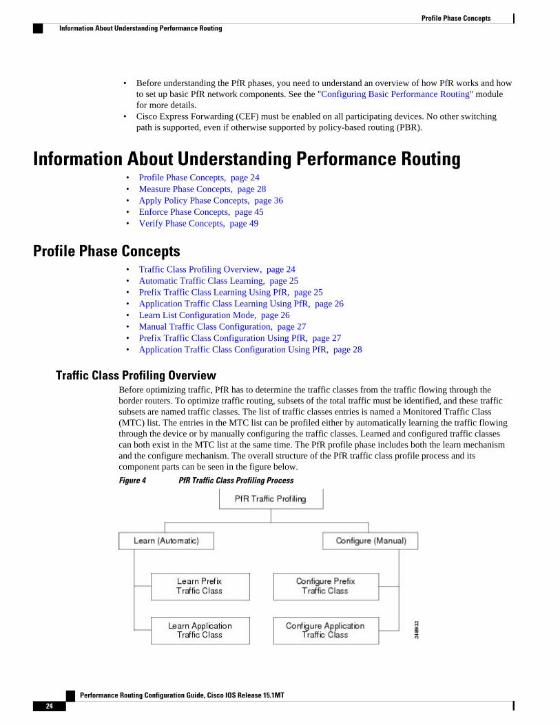
Traffic Class Profiling OverviewBefore optimizing traffic, PfR has to determine the traffic classes from the traffic flowing through theborder routers. To optimize traffic routing, subsets of the total traffic must be identified, and these trafficsubsets are named traffic classes. The list of traffic classes entries is named a Monitored Traffic Class(MTC) list. The entries in the MTC list can be profiled either by automatically learning the traffic flowingthrough the device or by manually configuring the traffic classes. Learned and configured traffic classescan both exist in the MTC list at the same time. The PfR profile phase includes both the learn mechanismand the configure mechanism. The overall structure of the PfR traffic class profile process and itscomponent parts can be seen in the figure below.
Figure 4 PfR Traffic Class Profiling Process
Profile Phase Concepts Information About Understanding Performance Routing
Performance Routing Configuration Guide, Cisco IOS Release 15.1MT24

The ultimate objective of this phase is to select a subset of traffic flowing through the network. This subsetof traffic--the traffic classes in the MTC list--represents the classes of traffic that need to be routed basedon the best performance path available.
Automatic Traffic Class LearningPfR can automatically learn the traffic classes while monitoring the traffic flow through border routers.Although the goal is to optimize a subset of the traffic, you may not know all the exact parameters of thistraffic and PfR provides a method to automatically learn the traffic and create traffic classes by populatingthe MTC list. Several features have been added to PfR since the original release to add functionality to theautomatic traffic class learning process.
Within the automatic traffic class learning process there are now three components. One componentdescribes the automatic learning of prefix-based traffic classes, the second component describes automaticlearning of application-based traffic classes, and the third component describes the use of learn lists tocategorize both prefix-based and application-based traffic classes. These three components are described inthe following sections:
Prefix Traffic Class Learning Using PfRThe PfR master controller can be configured, using NetFlow Top Talker functionality, to automaticallylearn prefixes based on the highest outbound throughput or the highest delay time. Throughput learningmeasures prefixes that generate the highest outbound traffic volume. Throughput prefixes are sorted fromhighest to lowest. Delay learning measures prefixes with the highest round-trip response time (RTT) tooptimize these highest delay prefixes to try to reduce the RTT for these prefixes. Delay prefixes are sortedfrom the highest to the lowest delay time.
PfR can automatically learn two types of prefixes:
• outside prefix--An outside prefix is defined as a public IP prefix assigned outside the company.Outside prefixes are received from other networks.
• inside prefix--An inside prefix is defined as a public IP prefix assigned to a company. An inside prefixis a prefix configured within the company network.
In the BGP Inbound Optimization feature the ability to learn inside prefixes was introduced. Using BGP,PfR can select inside prefixes to support best entrance selection for traffic that originates from prefixesoutside an autonomous system destined for prefixes inside the autonomous system. In prior releases, onlyoutside prefixes were supported. For more details about inside prefix PfR support, see the BGP InboundOptimization Using Performance Routing module.
Automatic prefix learning is configured in PfR Top Talker and Top Delay learning configuration mode.The learn (PfR) command is used to enter this mode from PfR master controller configuration mode. Whenautomatic prefix learning is enabled, prefixes and their delay or throughput characteristics are measured onthe border routers. Performance measurements for the prefix-based traffic classes are reported to the mastercontroller where the learned prefixes are stored in the MTC list.
Prefixes are learned on the border routers through monitoring the traffic flow using the embedded NetFlowcapability. All incoming and outgoing traffic flows are monitored. The top 100 flows are learned bydefault, but the master controller can be configured to learn up to 2500 flows for each learn cycle.
The master controller can be configured to aggregate learned prefixes based on type; BGP or non-BGP(static). Prefixes can be aggregated based on the prefix length. Traffic flows are aggregated using a /24prefix length by default. Prefix aggregation can be configured to include any subset or superset of thenetwork, from single host route (/32) to a major network address range. For each aggregated prefix, up to
Understanding Performance RoutingAutomatic Traffic Class Learning
Performance Routing Configuration Guide, Cisco IOS Release 15.1MT 25

five host addresses are selected to use as active probe targets. Prefix aggregation is configured with theaggregation-type(PfR) command in PfR Top Talker and Delay learning configuration mode.
Application Traffic Class Learning Using PfRPfR can learn Layer 3 prefixes, and Layer 4 options such as protocol or port numbers can be added asfilters to the prefix-based traffic class. The protocol and port numbers can be used to identify specificapplication traffic classes; protocol and port number parameters are monitored only within the context of aprefix and are not sent to the master controller database (MTC list). The prefix that carries the specifictraffic is then monitored by the master controller. PfR application traffic class learning also supportsDifferentiated Services Code Point (DSCP) values in addition to protocol and port numbers, and theseLayer 4 options are entered in the MTC list.
DSCP Value, Port, and Protocol Learning by PfR
PfR has the ability to filter and aggregate application traffic by DSCP value, port number or protocol.Traffic classes can be defined by a combination of keys comprising of protocol, port numbers, and DSCPvalues. The ability to filter out traffic that is not required, and the ability to aggregate the traffic in whichyou are interested, was introduced. Information such as protocol, port number, and DSCP value is now sentto the master controller database in addition to the prefix information. The new functionality allows PfR toboth actively and passively monitor application traffic. Using new CLI and access lists, PfR can beconfigured to automatically learn application traffic classes.
Learn List Configuration ModePfR supports a learn list configuration mode to simplify the learning of traffic classes. Learn lists are a wayto categorize learned traffic classes. In each learn list, different criteria including prefixes, applicationdefinitions, filters, and aggregation parameters for learning traffic classes can be configured. A traffic classis automatically learned by PfR based on each learn list criteria, and each learn list is configured with asequence number. The sequence number determines the order in which learn list criteria are applied. Learnlists allow different PfR policies to be applied to each learn list; in previous releases, the traffic classescould not be divided, and an PfR policy was applied to all the learned traffic classes.
Learn list configuration mode uses traffic-class commands to simplify the learning of traffic classes. Fourtypes of traffic classes--to be automatically learned--can be profiled:
• Traffic classes based on destination prefixes• Traffic classes representing custom application definitions using access lists• Traffic classes based on a static application mapping name with optional prefix lists to define
destination prefixes• Traffic classes based on a NBAR application mapping name with optional prefix lists to define
destination prefixes
Only one type of traffic-class command can be specified per learn list, and the throughput (PfR) anddelay (PfR) commands are also mutually exclusive within a learn list.
Static Application Mapping Using PfR
The static application mapping feature introduced the ability to define an application using a keyword tosimplify the configuration of application-based traffic classes. PfR uses well-known applications with fixedports, and more than one application may be configured at the same time. For more details about staticapplication mapping, see the Static Application Mapping Using Performance Routing feature.
Understanding Performance Routing Application Traffic Class Learning Using PfR
Performance Routing Configuration Guide, Cisco IOS Release 15.1MT26
PfR Application Mapping Using NBAR
PfR supports the ability to profile an application-based traffic class using NBAR. Network-BasedApplication Recognition (NBAR) is a classification engine that recognizes and classifies a wide variety ofprotocols and applications, including web-based and other difficult-to-classify applications and protocolsthat use dynamic TCP/UDP port assignments. PfR uses NBAR to recognize and classify a protocol orapplication, and the resulting traffic classes are added to the PfR application database to be passively andactively monitored. For more details about PfR application mapping using NBAR, see the PerformanceRouting with NBAR/CCE Application Recognition feature.
Manual Traffic Class ConfigurationPfR can be manually configured to create traffic classes for monitoring and subsequent optimizing.Automatic learning generally uses a default prefix length of /24 but manual configuration allows exactprefixes to be defined. Within the manual traffic class configuration process there are two components--manually configuring prefix-based traffic classes and manually configuring application-based trafficclasses, both of which are described in the following sections:
Prefix Traffic Class Configuration Using PfRA prefix or range of prefixes can be selected for PfR monitoring by configuring an IP prefix list. The IPprefix list is then imported into the MTC list by configuring a match clause in a PfR map. A PfR map issimilar to an IP route map. IP prefix lists are configured with the ip prefix-list command and PfR maps areconfigured with the pfr-map command in global configuration mode.
The prefix list syntax operates in a slightly different way with PfR than in regular routing. The ge keywordis not used and the le keyword is used by PfR to specify only an inclusive prefix. A prefix list can also beused to specify an exact prefix.
A master controller can monitor and control an exact prefix of any length including the default route. If anexact prefix is specified, PfR monitors only the exact prefix.
A master controller can monitor and control an inclusive prefix using thele keyword and the le-valueargument set to 32. PfR monitors the configured prefix and any more specific prefixes (for example,configuring the 10.0.0.0/8 le 32 prefix would include the 10.1.0.0/16 and the 10.1.1.0/24 prefixes) over thesame exit and records the information in the routing information base (RIB).
Note Use the inclusive prefix option with caution in a typical PfR deployment because of the potential increasein the amount of prefixes being monitored and recorded.
An IP prefix list with a deny statement can be used to configure the master controller to exclude a prefix orprefix length for learned traffic classes. Deny prefix list sequences should be applied in the lowest PfR mapsequences for best performance. The master controller can also be configured to tell border routers to filterout uninteresting traffic using an access list.
Note IP prefix lists with deny statements can be applied only to learned traffic classes.
Two types of prefix can be manually configured for PfR monitoring using an IP prefix list:
• outside prefix--An outside prefix is defined as a public IP prefix assigned outside the company.Outside prefixes are received from other networks.
Understanding Performance RoutingManual Traffic Class Configuration
Performance Routing Configuration Guide, Cisco IOS Release 15.1MT 27

• inside prefix--An inside prefix is defined as a public IP prefix assigned to a company. An inside prefixis a prefix configured within the company network.
In the BGP Inbound Optimization feature the ability to manually configure inside prefixes was introduced.Using BGP, PfR can be configured to select inside prefixes to support best entrance selection for traffic thatoriginates from prefixes outside an autonomous system destined for prefixes inside the autonomous system.In prior releases, only outside prefixes were supported.
For more details about inside prefix PfR support, see the BGP Inbound Optimization Using PerformanceRouting module.
Application Traffic Class Configuration Using PfRPfR supports the manual configuration of Layer 3 prefixes during the PfR profile phase. Application-awarerouting for policy-based routing (PBR) is also supported. Application-aware routing allows the selection oftraffic for specific applications based on values in the IP packet header, other than the Layer 3 destinationaddress through a named extended IP access control list (ACL). Only named extended ACLs are supported.The extended ACL is configured with a permit statement and then referenced in a PfR map. The protocoland port numbers can be used to identify specific application traffic classes, but protocol and port numberparameters are monitored only within the context of a prefix, and are not sent to the MTC list. Only theprefix that carries the specific application traffic is profiled by the master controller. With application-aware routing support, active monitoring of application traffic was supported. Passive monitoring ofapplication traffic is also supported. Application traffic classes can be defined using DSCP values as wellas protocol and port numbers. DSCP values, port numbers, and protocols in addition to prefixes, are all nowstored in the MTC list.
Learn list configuration mode uses match traffic-class commands under PfR map configuration mode tosimplify the configuration of traffic classes. Four types of traffic classes--to be manually configured--canbe profiled:
• Traffic classes based on destination prefixes• Traffic classes representing custom application definitions using access lists• Traffic classes based on a static application mapping name and a prefix list to define destination
prefixes• Traffic classes based on NBAR application mapping name and a prefix list to define destination
prefixes
Only one type of match traffic-class command can be specified per PfR map.
For a series of well-known applications, static ports have been defined and each application can be definedby entering a keyword. For more details about static application mapping, see the Static ApplicationMapping Using Performance Routing feature.
PfR supports the ability to profile an application-based traffic class using NBAR. NBAR is a classificationengine that recognizes and classifies a wide variety of protocols and applications, including web-based andother difficult-to-classify applications and protocols that use dynamic TCP/UDP port assignments. PfR usesNBAR to recognize and classify a protocol or application, and the resulting traffic classes are added to thePfR application database to be passively and actively monitored. For more details about PfR applicationmapping using NBAR, see the Performance Routing with NBAR/CCE Application Recognition feature.
Measure Phase Concepts• Traffic Class Performance Measurement Overview, page 29
• Traffic Class Performance Measurement Techniques, page 30
Measure Phase Concepts Application Traffic Class Configuration Using PfR
Performance Routing Configuration Guide, Cisco IOS Release 15.1MT28
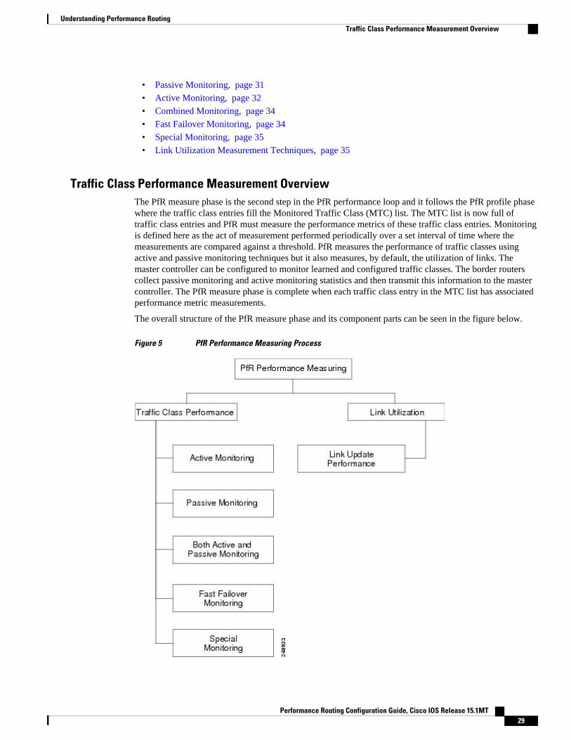
• Passive Monitoring, page 31
• Active Monitoring, page 32
• Combined Monitoring, page 34
• Fast Failover Monitoring, page 34
• Special Monitoring, page 35
• Link Utilization Measurement Techniques, page 35
Traffic Class Performance Measurement OverviewThe PfR measure phase is the second step in the PfR performance loop and it follows the PfR profile phasewhere the traffic class entries fill the Monitored Traffic Class (MTC) list. The MTC list is now full oftraffic class entries and PfR must measure the performance metrics of these traffic class entries. Monitoringis defined here as the act of measurement performed periodically over a set interval of time where themeasurements are compared against a threshold. PfR measures the performance of traffic classes usingactive and passive monitoring techniques but it also measures, by default, the utilization of links. Themaster controller can be configured to monitor learned and configured traffic classes. The border routerscollect passive monitoring and active monitoring statistics and then transmit this information to the mastercontroller. The PfR measure phase is complete when each traffic class entry in the MTC list has associatedperformance metric measurements.
The overall structure of the PfR measure phase and its component parts can be seen in the figure below.
Figure 5 PfR Performance Measuring Process
Understanding Performance RoutingTraffic Class Performance Measurement Overview
Performance Routing Configuration Guide, Cisco IOS Release 15.1MT 29

PfR measures the performance of both traffic classes and links, but before monitoring a traffic class or linkPfR checks the state of the traffic class or link. PfR uses a policy decision point (PDP) that operatesaccording to a traffic class state transition diagram.
After determining the state of the traffic class or link, PfR may initiate one of the following performancemeasuring processes.
Traffic Class Performance Measurement TechniquesPfR uses three methods of traffic class performance measurement:
• Passive monitoring--measuring the performance metrics of traffic class entries while the traffic isflowing through the device using NetFlow functionality.
• Active monitoring--creating a stream of synthetic traffic replicating a traffic class as closely aspossible and measuring the performance metrics of the synthetic traffic. The results of the performancemetrics of the synthetic traffic are applied to the traffic class in the MTC list. Active monitoring usesintegrated IP Service Level Agreements (IP SLAs) functionality.
• Both active and passive monitoring--combining both active and passive monitoring in order togenerate a more complete picture of traffic flows within the network.
Fast failover monitoring mode is another variation of the combined active and passive monitoring modes.In fast failover monitoring mode, all exits are continuously probed using active monitoring and passivemonitoring. When fast failover monitoring mode is enabled, the probe frequency can be set to a lowerfrequency than for other monitoring modes, to allow a faster failover capability.
No explicit NetFlow or IP SLAs configuration is required and support for NetFlow and IP SLAs is enabledautomatically. You can use both active and passive monitoring methods for a traffic class.
After the master controller is defined and PfR functionality is enabled, the master controller uses bothpassive and active monitoring by default. All traffic classes are passively monitored using integratedNetFlow functionality. Out-of-policy traffic classes are actively monitored using IP SLA functionality. Youcan configure the master controller to use only passive monitoring, active monitoring, both passive andactive monitoring, or fast failover monitoring. The main differences between the different modes can beseen in the table below.
Table 2 Mode Comparison Table
ComparisonParameter
Active Mode Passive Mode Combined Mode Fast Failover Mode
Active/IP SLA Yes No Yes Yes
Passive/NetFlow No Yes Yes Yes
Monitoring ofAlternate Paths
On Demand On Demand On Demand Continuous
Best Failover Time 10 seconds ~ 1 minute ~ 1.1 minute 3 seconds
Support for RoundTrip Delay
Yes Yes Yes Yes
Support for Loss Only with Jitterprobe
Only for TCPtraffic
Only for TCPtraffic
Only for TCPtraffic and Jitterprobe
Understanding Performance Routing Traffic Class Performance Measurement Techniques
Performance Routing Configuration Guide, Cisco IOS Release 15.1MT30

ComparisonParameter
Active Mode Passive Mode Combined Mode Fast Failover Mode
Support forReachability
Yes Only for TCPtraffic
Only for TCPtraffic
Yes
Support for Jitter Yes No No Yes
Support for MOS Yes No No Yes
In Cisco IOS Release 12.2(33)SXH support for using a Cisco Catalyst 6500 series switch as a PfR borderrouter was introduced. In Cisco IOS Release 12.2(33)SRB support for using a Cisco 7600 series router as aPfR border router was introduced. The master controller that communicates with the Cisco Catalyst 6500switch or a Cisco 7600 series router being used as a border router must be a router running Cisco IOSRelease 12.4(6)T or a later release because a special monitoring mode was introduced to support the limitedcapabilities for collecting passive statistics on the Catalyst 6500. The special mode is set globally andcannot be configured using the command-line interface (CLI).
Passive MonitoringCisco IOS PfR uses NetFlow, an integrated technology in Cisco IOS software, to collect and aggregatepassive monitoring statistics on a per traffic class basis. Passive monitoring is enabled along with activemonitoring by default when an PfR managed network is created. Passive monitoring can also be enabledexplicitly using the mode monitor passive command. Netflow is a flow-based monitoring and accountingsystem, and NetFlow support is enabled by default on the border routers when passive monitoring isenabled.
Passive monitoring uses only existing traffic; additional traffic is not generated. Border routers collect andreport passive monitoring statistics to the master controller approximately once per minute. If traffic doesnot go over an external interface of a border router, no data is reported to the master controller. Thresholdcomparison is done at the master controller. Passive monitoring supports traffic classes defined by prefix,port, protocol, and DSCP value.
PfR uses passive monitoring to measure the following metrics for all the traffic classes:
• Delay--PfR measures the average delay of TCP flows for a given prefix. Delay is the measurement ofthe round-trip response time (RTT) between the transmission of a TCP synchronization message andreceipt of the TCP acknowledgement.
• Packet loss--PfR measures packet loss by tracking TCP sequence numbers for each TCP flow. PfRestimates packet loss by tracking the highest TCP sequence number. If a subsequent packet is receivedwith a lower sequence number, PfR increments the packet loss counter. Packet loss is measured inpackets per million.
• Reachability--PfR measures reachability by tracking TCP synchronization messages that have beensent repeatedly without receiving a TCP acknowledgement.
• Throughput--PfR measures throughput by measuring the total number of bytes and packets for eachtraffic class for a given interval of time.
Note Although all traffic classes are monitored, delay, loss, and reachability information is captured only forTCP traffic flows. Throughput statistics are captured for all non-TCP traffic flows.
DSCP values, port numbers, and protocols in addition to prefixes, are all sent from border routers to themaster controller. Passive monitoring statistics are gathered and stored in a prefix history buffer that can
Understanding Performance RoutingPassive Monitoring
Performance Routing Configuration Guide, Cisco IOS Release 15.1MT 31
hold a minimum of 60 minutes of information depending on whether the traffic flow is continuous. PfRuses this information to determine if the prefix is in-policy based on the default or user-defined policies. Noalternative path analysis is performed as the traffic for a traffic class is flowing through one transit devicein the network. If the traffic class goes OOP and only passive monitoring mode is enabled, the traffic classis moved to another point and the measurement repeated until a good or best exit is found. If the trafficclass goes OOP and both passive and active monitoring modes are enabled, active probing is executed onall the exits and a best or good exit is selected.
Active MonitoringIf PfR passive monitoring techniques create too much overhead on a network device, or the performancemetrics of a traffic class cannot be measured using the PfR passive monitoring mode, then PfR activemonitoring techniques are performed. Active monitoring involves creating a stream of synthetic traffic thatreplicates a traffic class as closely as possible. The performance metrics of the synthetic traffic aremeasured and the results are applied to the traffic class entry in the MTC list. Active monitoring supportstraffic classes defined by prefix, port, protocol, and DSCP value.
PfR uses active monitoring to measure the following metrics for all the traffic classes:
• Delay--PfR measures the average delay of TCP, UDP, and ICMP flows for a given prefix. Delay is themeasurement of the round-trip response time (RTT) between the transmission of a TCPsynchronization message and receipt of the TCP acknowledgement.
• Reachability--PfR measures reachability by tracking TCP synchronization messages that have beensent repeatedly without receiving a TCP acknowledgement.
• Jitter--Jitter means interpacket delay variance. PfR measures jitter by sending multiple packets to atarget address and a specified target port number, and measuring the delay interval between packetsarriving at the destination.
• MOS--Mean Opinion Score (MOS) is a standards-based method of measuring voice quality. Standardsbodies like the ITU have derived two important recommendations: P.800 (MOS) and P.861(Perceptual Speech Quality Measurement [PSQM]). P.800 is concerned with defining a method toderive a Mean Opinion Score of voice quality. MOS scores range between 1 representing the worstvoice quality, and 5 representing the best voice quality. A MOS of 4 is considered "toll-quality" voice.
The creation of synthetic traffic in Cisco network devices is activated through the use of Cisco IOS IP SLAprobes. PfR is integrated with IP SLAs functionality such that PfR will use IP SLA probes to activelymonitor a traffic class. When active monitoring is enabled, the master controller commands the borderrouters to send active probes to set of target IP addresses. The border sends probe packets to no more thanfive target host addresses per traffic class, and transmits the probe results to the master controller foranalysis.
Active probe monitoring periods are defined as short-term which consists of the last 5 probe results, andlong-term which consists of the last 60 probe results.
IP SLA Active Probe Types Used by PfR
IP SLAs are an embedded feature set in Cisco IOS software and they allow you to analyze IP service levelsfor IP applications and services, to increase productivity, to lower operational costs, and to reduceoccurrences of network congestion or outages. IP SLAs use active traffic monitoring--the generation oftraffic in a continuous, reliable, and predictable manner--for measuring network performance. The accuracyof measured data is enhanced by enabling the IP SLAs Responder, available in Cisco routers, on thedestination device. For more details about IP SLAs, see the IP SLAs Configuration Guide.
The following types of active probes can be configured:
• ICMP Echo--A ping is sent to the target address. PfR uses ICMP Echo probes, by default, when anactive probe is automatically generated. Configuring an ICMP echo probe does not require
Understanding Performance Routing Active Monitoring
Performance Routing Configuration Guide, Cisco IOS Release 15.1MT32

knowledgeable cooperation from the target device. However, repeated probing could trigger anIntrusion Detection System (IDS) alarm in the target network. If an IDS is configured in a targetnetwork that is not under your control, we recommend that you notify the administrator of this targetnetwork.
• Jitter--A jitter probe is sent to the target address. A target port number must be specified. A remoteresponder must be enabled on the target device, regardless of the configured port number. Loss policyis supported for active monitoring if the jitter probe is used.
• TCP Connection--A TCP connection probe is sent to the target address. A target port number must bespecified. A remote responder must be enabled if TCP messages are configured to use a port numberother than TCP port number 23, which is well-known.
• UDP Echo--A UDP echo probe is sent to the target address. A target port number must be specified. Aremote responder must be enabled on the target device, regardless of which port number is configured.
PfR marks the probe packets with the DSCP value by default if the monitored traffic classes have theDSCP field set to a nonzero value.
Creation of Active Probe for a Traffic Class
To create an active probe for a traffic class, a probe type has to be discovered, and a probe target assignedto the traffic class. To discover a probe type, PfR uses one of the following methods:
• Learned probe--Active probes are automatically generated when a traffic class is learned using theNetFlow TopTalker Learn mechanism. Five targets are learned for each traffic class and, by default,the active probe is set as an ICMP echo probe.
• Configured probe--Active probes can also be configured on the master controller by specifying theprobe type, target address and port if needed. Configured traffic classes can be configured to use anyof the IP SLA active probes.
To assign a probe target for a traffic class, PfR uses one of the following methods:
• Longest match--By default, PfR assigns a probe target to the traffic class with the longest matchingprefix in the MTC list. This is referred to as a default probe assignment.
• Forced assignment--An IP SLA probe can be configured using a PfR map and the results of the probeare assigned to specific traffic classes associated with the PfR map. This specific assignment of activeprobe results is called a forced target probe assignment.
The active probe is sourced from the border router and transmitted through an external interface (theexternal interface may, or may not, be the preferred route for an optimized prefix). When creating an activeprobe through an external interface for a specified target, the target should be reachable through theexternal interface. To test the reachability of the specified target, PfR performs a route lookup in the BGPand static routing tables for the specified target and external interface. Protocol Independent RouteOptimization (PIRO) introduced the ability of PfR to search for a parent route--an exact matching route, ora less specific route--in any IP Routing Information Base (RIB). The BGP routing table is searched first,followed by the static routing table, and finally the RIB.
In active monitoring mode, the probes are activated from all the border routers to find the best performancepath for the specific traffic class. The active probes for that traffic class are not activated again unless thetraffic class goes OOP.
By default, the frequency of an active probe used by PfR is set to 60 seconds. The frequency of an activeprobe can be increased for each policy by configuring a lower time-interval between two probes. Increasedprobe frequency can reduce the response time and, for voice traffic, provide a better approximation of theMOS-low count percentage.
Understanding Performance RoutingActive Monitoring
Performance Routing Configuration Guide, Cisco IOS Release 15.1MT 33

PfR Active Probe Source Address
PfR supports the ability to configure an active probe source address. By default, active probes use thesource IP address of the PfR external interface that transmits the probe. The active probe source addressfeature is configured on the border router. When this command is configured, the primary IP address of thespecified interface is used as the active probe source. The active probe source interface IP address must beunique to ensure that the probe reply is routed back to the specified source interface. If the interface is notconfigured with an IP address, the active probe will not be generated. If the IP address is changed after theinterface has been configured as an active probe source, active probing is stopped, and then restarted withthe new IP address. If the IP address is removed after the interface has been configured as an active probesource, active probing is stopped and not restarted until a valid primary IP address is configured.
PfR Voice Traffic Optimization Using Active Probes
PfR supports outbound optimization of voice traffic using active probes on the basis of voice metrics suchas delay, reachability, jitter, and Mean Opinion Score (MOS).
For more details about optimizing voice traffic, see the "PfR Voice Traffic Optimization Using ActiveProbes" module.
Combined MonitoringCisco IOS PfR can also be configured to combine both active and passive monitoring in order to generate amore complete picture of traffic flows within the network. There are some scenarios in which you maywant to combine both PfR monitoring modes.
One example scenario is when you want to learn traffic classes and then monitor them passively, but youalso want to determine the alternate path performance metrics in order to control the traffic classes. Thealternate path performance metrics, in the absence of the actual traffic flowing through the alternate path inthe network, can be measured using the active probes. PfR automates this process by learning traffic classesat five targets and probing through all the alternate paths using active probes.
Fast Failover MonitoringFast monitoring sets the active probes to continuously monitor all the exits (probe-all), and passivemonitoring is enabled too. Fast failover monitoring can be used with all types of active probes: ICMP echo,Jitter, TCP connection, and UDP echo. When the mode monitor fast command is enabled, the probefrequency can be set to a lower frequency than for other monitoring modes, to allow a faster failoverability. Under fast monitoring with a lower probe frequency, route changes can be performed within 3seconds of an out-of-policy situation. When an exit becomes OOP under fast monitoring, the select bestexit is operational and the routes from the OOP exit are moved to the best in-policy exit. Fast monitoring isa very aggressive mode that incurs a lot of overhead with the continuous probing. We recommend that youuse fast monitoring only for performance sensitive traffic. For example, a voice call is very sensitive to anyperformance problems or congested links, but the ability to detect and reroute the call within a few secondscan demonstrate the value of using fast monitoring mode.
Note In fast monitoring mode, probe targets are learned as well as learned prefixes. To avoid triggering largenumbers of probes in the network, use fast monitoring mode only for real time applications and criticalapplications with performance sensitive traffic.
Understanding Performance Routing Combined Monitoring
Performance Routing Configuration Guide, Cisco IOS Release 15.1MT34

Special MonitoringThe PfR Border Router Only feature introduced the ability to run PfR on some hardware platforms that donot support the master controller functions but do allow these platforms to operate as border routers withlimited functionality. The master controller that communicates with the Cisco Catalyst 6500 series switchor a Cisco 7600 series router being used as a border router must be a router running Cisco IOS Release12.4(6)T or a later release.A special monitoring mode was introduced, mode monitor special, as an alternate syntax to mode monitorboth for the hardware platforms that do not support the master controller functions. The special mode is setglobally and cannot be configured using the command-line interface (CLI). On hardware platforms that donot support the master controller functions, PfR cannot determine performance characteristics such asdelay, loss, or reachability from passive monitoring of TCP flows; PfR can only measure passivethroughput. Throughput-based load balancing is still supported and active probing is enabled toaccommodate the passive monitoring limitations and this allows active IP SLA measurements. The mastercontroller automatically detects the limited capabilities of the Cisco Catalyst 6500 series switch or a Cisco7600 series router and downgrades other border routers to capture only the throughput statistics for trafficclasses. By ignoring other types of statistics, the master controller is presented with a uniform view of theborder router functionality.
Note The output from the show oer master prefix command lists an # next to the prefix with mode monitorspecial.
Link Utilization Measurement TechniquesLink Utilization ThresholdAfter an external interface is configured for a border router, PfR automatically monitors the utilization ofthe external link (an external link is an interface on a border router that typically links to a WAN). Every 20seconds, by default, the border router reports the link utilization to the master controller. Both egress(transmitted) and ingress (received) traffic utilization values are reported to the master controller. If the exitor entrance link utilization is above the default threshold of 75-percent, the exit or entrance link is in anOOP state and PfR starts the monitoring process to find an alternative link for the traffic class. The linkutilization threshold can be manually configured either as an absolute value in kilobytes per second (kbps)or as a percentage.Link Utilization RangePfR can also be configured to calculate the range of utilization over all the links. Both egress (transmitted)and ingress (received) traffic utilization values are reported to the master controller. In the diagram belowthere are two border routers with exits links to the Internet through two ISPs. The master controllerdetermines which link on one of the border routers--either BR1 or BR2 in the diagram below--is used by atraffic class.Figure 6 PfR network diagram
170913
ISP1/WAN1
ISP2/WAN2
MC
BR2
BR1
Understanding Performance RoutingSpecial Monitoring
Performance Routing Configuration Guide, Cisco IOS Release 15.1MT 35

PfR range functionality attempts to keep the exit or entrance links within a utilization range, relative toeach other to ensure that the traffic load is distributed. The range is specified as a percentage and isconfigured on the master controller to apply to all the exit or entrance links on border routers managed bythe master controller. For example, if the range is specified as 25-percent, and the utilization of the exit linkat BR1 (in the diagram above) is 70-percent, then if the utilization of the exit link at BR2 (in the diagramabove) falls to 40-percent, the percentage range between the two exit links will be more than 25-percentand PfR will attempt to move some traffic classes to use the exit link at BR1 to even the traffic load. If BR1(in the diagram above) is being configured as an entrance link, the link utilization range calculations workin the same way as for an exit link, except that the utilization values are for received traffic, not transmittedtraffic.
Note If you are configuring link grouping, configure the no max-range-utilization command because using alink utilization range is not compatible with using a preferred or fallback set of exit links configured forlink grouping.
Apply Policy Phase Concepts• Apply Policy Phase Overview, page 36
• PfR Policy Decision Point, page 37
• Traffic Class Performance Policies, page 38
• PfR Link Policies, page 40
• PfR Link Grouping, page 41
• PfR Network Security Policies, page 42
• PfR Policy Operational Options and Parameters, page 42
• PfR Policy Application, page 44
• Priority Resolution for Multiple PfR Policies, page 44
Apply Policy Phase OverviewThe PfR apply policy phase is the third step in the PfR performance loop following after the profile phasethat identifies the traffic classes, and the measure phase where each traffic class entry in the MTC list ismonitored to determine performance metric measurements. The apply policy phase compares the measuredperformance metrics against well-known or configured thresholds to determine if the traffic is meetingspecified levels of service, or if some action is required. If the performance metric does not conform to thethreshold, a decision is made by PfR to move the traffic class or exit into another state.
An PfR policy is a rule that defines an objective and contains the following attributes:
• A scope.• An action.• A triggering event or condition.
For example, a policy can be configured to maintain a delay of less than or equal to 100 milliseconds forpackets sent to a specific traffic class entry. The scope is the network traffic sent to the specific traffic classentry, the action is a routing table change, and the triggering event is a measured delay of greater than 100milliseconds for this traffic. The action may be not be executed until PfR is configured to control the trafficin the PfR control phase. By default, PfR runs in an observe mode during the profile, measure, and applypolicy phases.
Apply Policy Phase Concepts Apply Policy Phase Overview
Performance Routing Configuration Guide, Cisco IOS Release 15.1MT36

In the PfR apply policy phase you can configure and apply policies. Different types of PfR policies can beconfigured--see the figure below--and specific PfR parameters and options can be included within a policy.In this document, a parameter is a configurable element that can be fine-tuned, and an option is aconfigurable element that is either enabled or disabled. After an PfR policy is configured, the policy can beapplied to learned traffic classes or configured traffic classes. PfR policies can be applied globally--to allthe traffic classes--or to just a specific set of traffic classes.
Figure 7 PfR Apply Policy Phase Structure
In the figure above you can see that there are three types of PfR policies plus some operational options andparameters that can be configured. Use the following links to review more information about each policytype, parameter, or option:
After an PfR policy is configured, you can see from the figure above that a policy can be applied to learnedtraffic classes or configured traffic classes on a global basis for all traffic classes or for a specific set oftraffic classes.
When configuring multiple policy parameters for traffic classes, it is possible to have multiple overlappingpolicies. To resolve the potential conflict of which policy to run, PfR uses its resolve function: a flexiblemechanism that allows you to set the priority for most of the policy types.
PfR Policy Decision PointWhen running an PfR policy that compares the traffic class performance metrics with default or configuredthresholds, a traffic class may change state. PfR uses a policy decision point (PDP) that operates accordingto the traffic class state transition diagram shown in the figure below. The state transition diagram belowcontains the following states:
• Default--A traffic class is placed in the default state when it is not under PfR control. Traffic classesare placed in the default state when they are initially added to the central policy database, the MTC. Atraffic class will transition into and out of the default state depending on performance measurements,timers, and policy configuration.
• Choose Exit--This is a temporary state in which the PDP compares the current state of the traffic classagainst its policy settings and chooses the optimal exit for the traffic class. PfR will try to keep a trafficclass flowing through its current exit but, as in the default state, performance measurements, timers,and policy configurations can cause the master controller to place a traffic class in this state for the
Understanding Performance RoutingPfR Policy Decision Point
Performance Routing Configuration Guide, Cisco IOS Release 15.1MT 37

duration of the exit link selection process. The traffic class remains in the choose exit state until it ismoved to the new exit.
• Holddown--A traffic class is placed in the holddown state when the master controller requests a borderrouter to forward the traffic class to be monitored using probes. Measurements are collected for theselected traffic class until the holddown timer expires unless the exit used by this traffic class isdeclared unreachable. If the exit is unreachable, the traffic class transitions back to the choose exitstate.
Figure 8 PfR Traffic Class State Transition Diagram
17
08
85
Default
In Policy
Choose ExitOut of Policy Holddown
• In-Policy--After performance measurements are compared against default or user-defined policysettings and an exit selection is made, the traffic class enters an in-policy state. When a traffic class isin the in-policy state, the traffic class is forwarded through an exit that satisfies the default or user-defined settings. The master controller continues to monitor the traffic class, but no action is takenuntil the periodic timer expires, or an out-of-policy message is received from a measurement collector,when the traffic class transitions back to the choose exit state.
Note When observe mode is running, a prefix goes into an in-policy state only if the exit selected for that prefixis the current exit.
• Out-of-Policy (OOP)--A traffic class is placed in this state when there are no exits through which toforward the traffic class that conform to default or user-defined policies. While the traffic class is inthis state, the backoff timer controls exiting from this state. Each time the traffic class enters this state,the amount of time the traffic class spends in this state increases. The timer is reset for a traffic classwhen the traffic class enters an in-policy state. If all exit links are out-of-policy, the master controllermay select the best available exit.
Traffic Class Performance PoliciesPfR traffic class performance policies are a set of rules that govern performance characteristics for trafficclasses that can be network addresses (prefixes) or application criteria such as protocol, port number, orDSCP value. Network addresses can refer to individual endpoints within a network (e.g. 10.1.1.1/32) or toentire subnets (e.g. 10.0.0.0/8). The major performance characteristics that can be managed within an PfRpolicy are:
Understanding Performance Routing Traffic Class Performance Policies
Performance Routing Configuration Guide, Cisco IOS Release 15.1MT38

With the exception of reachability, none of these performance characteristics can be managed within theconstructs of conventional routing protocol metrics. Cisco PfR extends the concept of reachability (beyondensuring that a particular route exists in the routing table) by automatically verifying that the destinationcan be reached through the indicated path. Using Cisco PfR provides the network administrator with a newand powerful toolset for managing the flow of traffic.
Reachability
Reachability is specified as the relative percentage or the absolute maximum number of unreachable hosts,based on flows per million (fpm), that PfR will permit from a traffic class entry. If the absolute number orrelative percentage of unreachable hosts is greater than the user-defined or the default value, PfRdetermines that the traffic class entry is out-of-policy and searches for an alternate exit link.
To configure parameters for reachability, use the unreachable (PfR) command. This command has twokeywords, relative and threshold. The relative keyword is used to configure the relative percentage ofunreachable hosts. The relative unreachable host percentage is based on a comparison of short-term andlong-term measurements. The short-term measurement reflects the percentage of hosts that are unreachablewithin a 5-minute period. The long-term measurement reflects the percentage of unreachable hosts within a60-minute period. The following formula is used to calculate this value:
Relative percentage of unreachable hosts = ((short-term percentage - long-term percentage) / long-termpercentage) * 100
The master controller measures the difference between these two values as a percentage. If the percentageexceeds the user-defined or default value, the traffic class entry is determined to be out-of-policy. Forexample, if 10 hosts are unreachable during the long-term measurement and 12 hosts are unreachableduring short-term measurement, the relative percentage of unreachable hosts is 20 percent.
The threshold keyword is used to configure the absolute maximum number of unreachable hosts. Themaximum value is based on the actual number of hosts that are unreachable based on fpm.
Delay
Delay (also referred as latency) is defined as the delay between when the packet was sent from the sourcedevice and when it arrived at a destination device. Delay can be measured as one-way delay or round-tripdelay. The largest contributor to latency is caused by network transmission delay.
PfR supports defining delay performance characteristics with respect to voice traffic. Round-trip delayaffects the dynamics of conversation and is used in Mean Opinion Score (MOS) calculations. One-waydelay is used for diagnosing network problems. A caller may notice a delay of 200 milliseconds and try tospeak just as the other person is replying because of packet delay. The telephone industry standardspecified in ITU-T G.114 recommends the maximum desired one-way delay be no more than 150milliseconds. Beyond a one-way delay of 150 milliseconds, voice quality is affected. With a round-tripdelay of 300 milliseconds or more, users may experience annoying talk-over effects.
Packet Loss
Packet loss can occur due an interface failing, a packet being routed to the wrong destination, or congestionin the network.
Packet loss for voice traffic leads to the degradation of service in which a caller hears the voice sound withbreaks. Although average packet loss is low, voice quality may be affected by a short series of lost packets.
Jitter
PfR supports defining jitter performance characteristics. Jitter means interpacket delay variance. Whenmultiple packets are sent consecutively from source to destination, for example, 10 ms apart, and if the
Understanding Performance RoutingTraffic Class Performance Policies
Performance Routing Configuration Guide, Cisco IOS Release 15.1MT 39

network is behaving ideally, the destination should be receiving them 10 ms apart. But if there are delays inthe network (like queuing, arriving through alternate routes, and so on) the arrival delay between packetsmight be greater than or less than 10 ms. Using this example, a positive jitter value indicates that thepackets arrived more than 10 ms apart. If the packets arrive 12 ms apart, then positive jitter is 2 ms; if thepackets arrive 8 ms apart, then negative jitter is 2 ms. For delay-sensitive networks like VoIP, both positiveand negative jitter values are undesirable; a jitter value of 0 is ideal.
Mean Opinion Score (MOS)
PfR supports defining MOS performance characteristics. With all the factors affecting voice quality, manypeople ask how voice quality can be measured. Standards bodies like the ITU have derived two importantrecommendations: P.800 (MOS) and P.861 (Perceptual Speech Quality Measurement [PSQM]). P.800 isconcerned with defining a method to derive a Mean Opinion Score of voice quality. MOS scores rangebetween 1 representing the worst voice quality, and 5 representing the best voice quality. A MOS of 4 isconsidered "toll-quality" voice.
Jitter and MOS performance characteristic can be configured in an PfR policy as well as delay and packetloss to determine the quality of a phone call over an IP network.
PfR Link PoliciesPfR link policies are a set of rules that are applied against PfR-managed external link (an external link is aninterface on a border router on the network edge). Link policies define the desired performancecharacteristics of the links. Instead of defining the performance of an individual traffic class entry that usesthe link (as in traffic class performance policies), link policies are concerned with the performance of thelink as a whole. Link policies can be applied to exit (egress) links and entrance (ingress) links. Thefollowing performance characteristics are managed by link policies:
• Traffic Load (Utilization)• Range• Cost
Traffic Load
A traffic load (also referred to as utilization) policy consists of an upper threshold on the amount of trafficthat a specific link can carry. Cisco IOS PfR supports per traffic class load distribution. Every 20 seconds,by default, the border router reports the link utilization to the master controller, after an external interface isconfigured for a border router. Exit link and entrance link traffic load thresholds can be configured as anPfR policy. If the exit or entrance link utilization is above the configured threshold, or the default thresholdof 75-percent, the exit or entrance link is in an OOP state and PfR starts the monitoring process to find analternative link for the traffic class. The link utilization threshold can be manually configured either as anabsolute value in kilobits per second (kbps) or as a percentage. A load utilization policy for an individualinterface is configured on the master controller under the border router configuration.
Tip When configuring load distribution, we recommend that you set the interface load calculation on externalinterfaces to 30-second intervals with the load-interval (PfR) interface configuration command. Thedefault calculation interval is 300 seconds. The load calculation is configured under interface configurationmode on the border router. This configuration is not required, but it is recommended to allow Cisco IOSPfR to respond as quickly as possible to load distribution issues.
Understanding Performance Routing PfR Link Policies
Performance Routing Configuration Guide, Cisco IOS Release 15.1MT40

Range
A range policy is defined to maintain all links within a certain utilization range, relative to each other inorder to ensure that the traffic load is distributed. For example, if a network has multiple exit links, andthere is no financial reason to choose one link over another, the optimal choice is to provide an even loaddistribution across all links. The load-sharing provided by traditional routing protocols is not always evenlydistributed, because the load-sharing is flow-based rather than performance- or policy-based. Cisco PfRrange functionality allows you to configure PfR to maintain the traffic utilization on a set of links within acertain percentage range of each other. If the difference between the links becomes too great, PfR willattempt to bring the link back to an in-policy state by distributing traffic classes among the available links.The master controller sets the maximum range utilization to 20 percent for all PfR-managed links bydefault, but the utilization range can be configured using a maximum percentage value. Exit link andentrance link utilization ranges can be configured as a PfR policy.
Note If you are configuring link grouping, configure the no max-range-utilization command because using alink utilization range is not compatible with using a preferred or fallback set of exit links configured forlink grouping.
Cost
Cost-based optimization allow you to configure policies based on the monetary cost (ISP service levelagreements [SLAs]) of each exit link in your network. To implement PfR cost-based optimization the PfRmaster controller is configured to send traffic over exit links that provide the most cost-effective bandwidthutilization, while still maintaining the desired performance characteristics.
Cost Based Optimization can be applied to links that are billed using a fixed or tiered billing method andload balancing based on cost can also be achieved. For more configuration details, see the “ConfiguringPerformance Routing Cost Policies” module.
PfR Link GroupingIn the Performance Routing - Link Groups feature, the ability to define a group of exit links as a preferredset of links, or a fallback set of links for PfR to use when optimizing traffic classes specified in an PfRpolicy, was introduced. PfR currently selects the best link for a traffic class based on the preferencesspecified in a policy and the traffic class performance--using parameters such as reachability, delay, loss,jitter or MOS--on a path out of the specified link. Bandwidth utilization, cost, and the range of links canalso be considered in selecting the best link. Link grouping introduces a method of specifying preferredlinks for one or more traffic classes in an PfR policy so that the traffic classes are routed through the bestlink from a list of preferred links, referred to as the primary link group. A fallback link group can also bespecified in case there are no links in the primary group that satisfy the specified policy and performancerequirements. If no primary group links are available, the traffic classes are routed through the best linkfrom the fallback group. To identify the best exit, PfR probes links from both the primary and fallbackgroups.
Note If you are configuring link grouping, configure the no max-range-utilization command because using alink utilization range is not compatible with using a preferred or fallback set of exit links configured forlink grouping.
For more details about PfR link grouping, see the “Performance Routing Link Groups” module.
Understanding Performance RoutingPfR Link Grouping
Performance Routing Configuration Guide, Cisco IOS Release 15.1MT 41

PfR Network Security PoliciesThe ability to configure network security policies either to prevent unauthorized use of the network or tomitigate attacks inside and outside the network is provided by PfR. You can configure PfR to use blackhole or sinkhole routing techniques to limit the impact of attacks against your network. Black hole routingrefers to the process of forwarding packets to a null interface, meaning that the packets are dropped into a"black hole." Sinkhole routing directs packets to a next hop where the packets can be stored, analyzed, ordropped. Another term for sinkhole routing is honey-pot routing.
PfR Policy Operational Options and ParametersIn addition to the specific types of PfR policies, there are some PfR policy operational parameters oroptions that can be configured. The operational parameters are timers and the operational options consist ofdifferent operational modes. For more details, see the following sections:
• PfR Timers Parameters, page 42
• PfR Mode Options, page 43
PfR Timers Parameters
Three types of timers can be configured as PfR policy operational parameters:
Backoff Timer
The backoff timer is used to adjust the transition period that the master controller holds an out-of-policytraffic class entry. The master controller waits for the transition period before making an attempt to find anin-policy exit. A minimum, a maximum, and an optional step timer value can be configured.
Holddown Timer
The holddown timer is used to configure the traffic class entry route dampening timer to set the minimumperiod of time that a new exit must be used before an alternate exit can be selected. To prevent the trafficclass entry from flapping because of rapid state changes, the master controller does not move the trafficclass entry to a different exit even if it goes out-of-policy during the holddown timer period. PfR does notimplement policy changes while a traffic class entry is in the holddown state. A traffic class entry willremain in a holddown state for the default or configured time period. When the holddown timer expires,PfR will select the best exit based on performance and policy configuration. However, an immediate routechange will be triggered if the current exit for a traffic class entry becomes unreachable.
Periodic Timer
The periodic timer is used to find a better path for a traffic class entry, even if the traffic class entry is in-policy on the current exit. When the periodic timer expires, the master controller evaluates current exitlinks for the traffic class entry and, if a better exit exists based on the current measurements and priorities,the traffic class entry is moved to a new in-policy exit link.
When adjusting PfR timers note that a newly configured timer setting will immediately replace the existingsetting if the value of the new setting is less than the time remaining. If the value is greater than the timeremaining, the new setting will be applied when the existing timer expires or is reset.
Understanding Performance Routing PfR Network Security Policies
Performance Routing Configuration Guide, Cisco IOS Release 15.1MT42

Note Overly aggressive timer settings can keep an exit link or traffic class entry in an out-of-policy state.
PfR Mode Options
Three types of mode options can be configured as PfR policy operational options:
Mode Monitor
The mode monitor option enables the configuration of PfR monitoring settings. Monitoring is defined hereas the act of measurement performed periodically over a set interval of time where the measurements arecompared against a threshold. PfR measures the performance of traffic classes using active and passivemonitoring techniques but it also measures, by default, the utilization of exit links.
Mode Route
The mode route option specifies one of three PfR route control policy settings. Mode route control enablesPfR to control routes automatically, mode route metric specifies PfR route protocol-related settings, andmode route observe offers route control advice, but does not take any action. Observe mode monitoring isenabled by default when PfR is enabled. In observe mode, the master controller monitors traffic classes andexit links based on default and user-defined policies and then reports the status of the network and thedecisions that should be made but does not implement any changes. Observe mode is used to verify theeffect of PfR features before PfR is actively deployed on your network.
If you have different routing protocols operating on your PfR border routers (for example, BGP on oneborder router and EIGRP on another) you must configure the protocol and pbr keywords with the moderoute command to allow destination-only traffic classes to be controlled using dynamic PBR. Entering theno mode route protocol pbr command will initially set the destination-only traffic classes to beuncontrolled and PfR then reverts to the default behavior using a single protocol to control the traffic classin the following order; BGP, EIGRP, static, and PBR.
Mode Select-Exit
The mode select-exit option enables the exit selection settings. The definition of an in-policy traffic classentry is that the measured performance metrics do not exceed a default or configured threshold while thetraffic class entry is on the current path. In this situation, PfR does not search for an alternate exit linkbecause the current network path keeps the traffic class entry in-policy. This type of configuration would beactivated by using the mode select-exit good command which is the default if the mode (PfR) command isnot specified. There are other deployment scenarios, where PfR selects the best performance path. Thistype of configuration can be activated by using the mode select-exit best command. In this type ofsituation, PfR measures alternate path performance metrics while the traffic class entry is in-policy on thecurrent path. PfR moves the current path if a better performance path is found. After the first selection ofthe best path, however, PfR does not initiate another search unless the periodic timer is configured. Whenthe periodic timer expires, the master controller evaluates current exit links for the traffic class entry and, ifa better exit exists based on the current measurements and priorities, the traffic class entry is moved to anew in-policy exit link. Use the periodic timer with the mode select-exit best command if you have adeployment scenario where you need PfR to select the best performance path at any given time.
There is one further use of the mode select-exit option. If PfR does not find an in-policy exit for a trafficclass entry when the mode select-exit good command is operational, PfR transitions the traffic class entryto an uncontrolled state. If PfR does not find an in-policy exit for a traffic class entry when the modeselect-exit best command is operational, PfR selects the best of the OOP exit links for the traffic classentry.
Understanding Performance RoutingPfR Mode Options
Performance Routing Configuration Guide, Cisco IOS Release 15.1MT 43

PfR Policy ApplicationPfR policies can be applied to learned or configured traffic classes. PfR policies can be applied on a globalbasis when the policy is configured directly under PfR master controller configuration mode. All trafficclasses inherit global policies. If, however, you want to apply a policy to a subset of the traffic classes, thena specific policy can be configured. A specific PfR policy applies only to the specific traffic classes thatmatch a prefix list or access list. Specific policies inherit global policies unless the same policy isoverwritten by the specific policy. PfR policies can apply to prefixes alone, or PfR policies can apply totraffic classes that define an application traffic class and may include prefixes, protocols, port numbers, andDSCP values. To apply specific policies to learned or configured traffic classes, PfR map configuration isused.
PfR Map Configuration for PfR Policies
A PfR map may appear to be similar to a route map but there are significant differences. A PfR map isdesigned to select learned or configured traffic classes using a match clause and then to apply PfR policyconfigurations using a set clause. The PfR map can be optionally configured with a sequence number like aroute map, but only the PfR map with the lowest sequence number is evaluated. The operation of a PfRmap differs from a route map at this point. There are two important distinctions:
• Only a single match clause may be configured for each sequence. An error message will be displayedon the console if you attempt to configure multiple match clauses for a single PfR map sequence.
• A PfR map is not configured with permit or deny statements. However, a permit or deny sequence canbe configured for an IP traffic flow by configuring a permit or deny statement in an IP prefix list andthen applying the prefix list to the PfR map.
Note Match precedence priority is not supported in PfR maps.
The PfR map applies the configuration of the set clause after a successful match occurs. A PfR set clausecan be used to set policy parameters such as the backoff timer, packet delay, holddown timer, packet loss,mode settings, periodic timer, resolve settings, unreachable hosts, and traceroute reporting.
Policies applied by an PfR map take effect immediately. The PfR map configuration can be viewed in theoutput of the show running-config command. PfR policy configuration can be viewed in the output of theshow pfr master policy command. These policies are applied only to traffic classes that match or passthrough the PfR map.
Policy Rules Configuration to Apply an PfR Policy
The policy-rules (PfR) command allows you to select a PfR map using a sequence number and apply theconfiguration under PfR master controller configuration mode, providing an improved method to switchbetween predefined PfR maps. Only one PfR map is used at a time for policy configuration, but many PfRmaps can be defined.
Priority Resolution for Multiple PfR PoliciesWhen configuring multiple policy criteria for a single traffic class entry, or a set of traffic classes, it ispossible to have multiple overlapping policies. To resolve the potential conflict of which policy to run, PfRuses its resolve function: a flexible mechanism that allows you to set the priority for a PfR policy. Eachpolicy is assigned a unique value, and the policy with the lowest value is selected as the highest prioritypolicy. By default, PfR assigns the highest priority to delay policies, followed by utilization policies.
Understanding Performance Routing PfR Policy Application
Performance Routing Configuration Guide, Cisco IOS Release 15.1MT44

Assigning a priority value to any policy will override the default settings. To configure the policy conflictresolution, use the resolve (PfR) command in PfR master controller configuration mode, or the set resolve(PfR) command in PfR map configuration mode.
Variance Setting for PfR Policy Conflict Resolution
When configuring PfR resolve settings, you can also set an allowable variance for the defined policy.Variance configures the average delay, as a percentage, that all traffic classes for one exit, or the specificpolicy traffic classes for an exit, can vary from the defined policy value and still be considered equivalent.For example, if the delay on the best exit link (best exit in terms of delay) for a traffic class entry is 80milliseconds (ms) and a 10 percent variance is configured, then any other exit links with a delay between80 and 88 ms for the same traffic class entry are considered equivalent to the best exit link.
To illustrate how variance is used by PfR consider three exit links with the following performance valuesfor delay and jitter for a traffic class entry:
• Exit A--Delay is 80 ms, jitter is 3ms• Exit B--Delay is 85 ms, jitter is 1ms• Exit C--Delay is 100 ms, jitter is 5ms
The following PfR policy conflict resolution is configured and applied to the traffic class entry:
delay priority 1 variance 10jitter priority 2 variance 10
PfR determines the best exit by looking at the policy with the lowest priority value, which in this exampleis the delay policy. Exit A has the lowest delay value, but Exit B has a delay value of 85 which is within a10-percent variance of the delay value at Exit A. Exit A and Exit B can therefore be considered equal interms of delay values. Exit C is now eliminated because the delay values are too high. The next prioritypolicy is jitter, and Exit B has the lowest jitter value. PfR will select Exit B as the only best exit for thetraffic class entry because Exit A has a jitter value that is not within 10-percent variance of the Exit B jittervalue.
Note Variance cannot be configured for cost or range policies.
Enforce Phase Concepts• PfR Enforce Phase Overview, page 45• PfR Traffic Class Control Techniques, page 46• PfR Exit Link Selection Control Techniques, page 47• PfR Entrance Link Selection Control Techniques, page 49
PfR Enforce Phase OverviewAfter profiling the traffic classes during the PfR learn phase, measuring the performance metrics of thetraffic classes during the measure phase, and using network policies to map the measured performancemetrics of traffic class entries in the Monitored Traffic Class (MTC) list against well-known or configuredthresholds to determine if the traffic is meeting specified levels of service in the policy phase, the next stepin the PfR performance loop is the PfR enforce phase.
PfR, by default, operates in an observation mode and the documentation for the PfR learn, measure, andapply policy phases assumes that PfR is in the observe mode. In observe mode, the master controller
Enforce Phase ConceptsPfR Enforce Phase Overview
Performance Routing Configuration Guide, Cisco IOS Release 15.1MT 45

monitors traffic classes and exit links based on default and user-defined policies and then reports the statusof the network including out-of-policy (OOP) events and the decisions that should be made, but does notimplement any changes. The PfR enforce phase operates in control mode, not observe mode, and controlmode must be explicitly configured using the mode route control command. In control mode, the mastercontroller coordinates information from the borders routers in the same way as observe mode, butcommands are sent back to the border routers to alter routing in the PfR managed network to implement thepolicy decisions.
PfR initiates route changes when one of the following occurs:
• A traffic class goes OOP.• An exit link goes OOP.• The periodic timer expires and the select exit mode is configured as select best mode.
During the PfR enforce phase, the master controller continues to monitor in-policy traffic classes thatconform to the desired performance characteristics, to ensure that they remain in-policy. Changes are onlyimplemented for OOP traffic classes and exits in order to bring them in-policy. To achieve the desired levelof performance in your network, you must be aware of the configuration options that can affect the policydecisions made by the master controller.
Another configuration issue to consider when deploying PfR is that if aggressive delay or loss policies aredefined, and the exit links are also seriously over-subscribed, it is possible that PfR will find it impossibleto bring a traffic class in-policy. In this case, the master controller will either choose the link that mostclosely conforms to the performance policy, even though the traffic class still remains OOP, or it willremove the prefix from PfR control. PfR is designed to allow you to make the best use of availablebandwidth, but it does not solve the problem of over-subscribed bandwidth.
After PfR control mode is enabled, and configuration options are considered, the next step is to review thetraffic class control techniques employed by PfR.
PfR Traffic Class Control TechniquesAfter the PfR master controller has determined that it needs to take some action involving an OOP trafficclass or exit link, there are a number of techniques that can be used to alter the routing metrics, alter BGPattributes, or introduce policy-based routing using a route map to influence traffic to use a different link. Ifthe traffic associated with the traffic class is defined only by a prefix then a traditional routing controlmechanism such as introducing a BGP route or a static route can be deployed. This control is network wideafter redistribution because a prefix introduced into the routing protocol with a better metric will attracttraffic for that prefix towards a border router. If the traffic associated with the traffic class is defined by aprefix and other matching criteria for the packet (application traffic, for example), then traditional routingcannot be employed to control the application traffic. In this situation, the control becomes device specificand not network specific. This device specific control is implemented by PfR using policy-based routing(PBR) functionality. If the traffic in this scenario has to be routed out to a different device, the remoteborder router should be a single hop away or a tunnel interface that makes the remote border router looklike a single hop.
Understanding Performance Routing PfR Traffic Class Control Techniques
Performance Routing Configuration Guide, Cisco IOS Release 15.1MT46

The figure below shows the various traffic class control techniques grouped by exit or entrance linkselection.
Figure 9 Controlling Traffic Class Techniques
PfR Exit Link Selection Control TechniquesBefore introducing the exit link selection control techniques you need to understand one principle aboutload balancing with Performance Routing as it applies to exit selection. PfR does not treat a more specificroute as a parent route unless you configure the more specific route as a default route.
When searching for a parent route, the software tries to find the most specific route that includes thespecified prefix and verifies that it points to the expected exit. If there are two or more static routes that aremore specific, each route is inspected for the expected exit. If the expected exit is found, the probe iscreated.
In the configuration where:
ip route 10.4.0.0 255.255.0.0 172.17.40.2ip route 0.0.0.0 0.0.0.0 serial 6/0
Probes for prefix 10.4.1.0/24 and target 10.4.1.1 will not be created over the exit using serial interface 6/0because the most specific route inclusive of 10.4.1.1 is the exit to 172.17.40.2. If you are looking to loadbalance the traffic over both exits, the answer is to create a default route of the more specific route. Forexample:
ip route 10.4.0.0 255.255.0.0 172.17.40.2ip route 10.4.0.0 255.255.0.0 serial 6/0
Or
ip route 0.0.0.0 0.0.0.0 serial 6/0ip route 0.0.0.0 0.0.0.0 172.17.40.2
In the modified configuration, two probes are created, one for the exit to 172.17.40.2 and one for the exitusing serial interface 6/0.
To enforce an exit link selection, PfR offers the following methods:
Understanding Performance RoutingPfR Exit Link Selection Control Techniques
Performance Routing Configuration Guide, Cisco IOS Release 15.1MT 47

Static Route Injection
A PfR master controller can enforce the use of a particular border router as the preferred exit link for atraffic class by injecting temporary static routes. These static routes exist only in the memory of the router,and are intentionally not saved to the permanent configuration. There are a few different methods that themaster controller can use to inject static routes on the border routers. Existing static routes can beoverwritten with new static routes, which have a better routing metric. If a default route, or even a lessspecific route, exists on the border router, the master controller can add a specific static route for themonitored traffic classes, which will be preferred to the existing default route. Finally, the master controllercan also use something known as split prefixes.
A split prefix refers to the addition of a more specific route, which will be preferred over a less specificroute. For example, if the border router already has a route of 10.10.10.0/24, adding a static route of10.10.10.128/25 will also cause the addresses 10.10.10.129-10.10.10.254 to be forwarded using the newlyinjected route. If PfR has been configured to monitor a subset of a larger network, it will add an appropriateroute to the existing routing table. PfR can use split prefixes to redirect subsets of an existing prefix to amore optimal exit link, and can use split prefixes for both internal BGP (iBGP) and static routes.
PfR will never inject a route where one does not already exist in the routing protocol table. Before injectinga route of a particular type, PfR will verify that a route exists in the BGP or static table that includes theprefix and points to the exit link. This route may be a default route.
BGP Control Techniques
PfR uses two BGP techniques to enforce the best exit path; injecting a BGP route, or modifying the BGPlocal preference attribute.
If the traffic associated with the traffic class is defined only by a prefix, the master controller can instruct aborder router to inject a BGP route into the BGP table to influence traffic to use a different link. All PfRinjected routes remain local to an autonomous system, and these injected routes are never shared withexternal BGP peers. As a safeguard to ensure this behavior, when PfR injects a BGP route, it will set theno-export community on it. This is done automatically, and does not require any user configuration.However, because these routes now have a special marking, some extra configuration is required to allowthe information to be shared with internal BGP peers. For each iBGP peer, the send communityconfiguration must be specified. Although the border routers know about the best exit for the injected route,it may also be necessary to redistribute this information further into the network.
PfR also uses BGP local preference to control traffic classes. BGP local preference (Local_Pref) is adiscretionary attribute applied to a BGP prefix to specify the degree of preference for that route duringroute selection. The Local_Pref is a value applied to a BGP prefix, and a higher Local_Pref value causes aroute to be preferred over an equivalent route. The master controller instructs one of the border routers toapply the Local_Pref attribute to a prefix or set of prefixes associated with a traffic class. The border routerthen shares the Local_Pref value with all of its internal BGP peers. Local_Pref is a locally significant valuewithin an autonomous system, but it is never shared with external BGP peers. Once the iBGPreconvergence is complete, the router with the highest Local_Pref for the prefix will become the exit linkfrom the network.
Note If a local preference value of 5000 or higher has been configured for default BGP routing, you shouldconfigure a higher BGP local preference value in PfR using the mode (PfR) command.
EIGRP Route Control
The PfR EIGRP mGRE DMVPN Hub-and-Spoke Support feature introduced PfR route control for EIGRP.When enabled, a parent route check is performed in the EIGRP database for controlling PfR prefixes/routes
Understanding Performance Routing PfR Exit Link Selection Control Techniques
Performance Routing Configuration Guide, Cisco IOS Release 15.1MT48

in addition to the existing BGP and static route databases. For more details, see the "Using PerformanceRouting to Control EIGRP Routes with mGRE DMVPN Hub-and-Spoke Support" module.
Policy-Based Routing Control
PfR can control application traffic using policy-based routing. Application traffic traveling through aparticular PfR border router can be identified by matching traffic defined in a PfR map as part of a PfRpolicy. The match ip address (PfR) command was enhanced to support extended ACLs. The extendedACL is referenced in an PfR map, and a single match clause can be configured for each PfR map sequence.Set clauses are configured to apply independent PfR policies to the matched traffic, which is a subset of amonitored prefix. The PfR policy is applied to all border routers to enforce policy routing for theapplication. Matched traffic is policy routed through the PfR external interface that conforms to policyparameters.
DSCP values, as well as prefixes, port numbers, and protocols, can all be used to identify and controlapplication traffic. DSCP values, protocols, and port numbers are sent by the border routers to the mastercontroller for inclusion in the MTC list.
Protocol Independent Route Optimization (PIRO)
PIRO was introduced to extend the ability of PfR to identify and control traffic classes. Prior to PIRO, PfRoptimizes paths for traffic classes that have a parent route--an exact matching route, or a less specificroute--in BGP or static route databases. PIRO enables PfR to search the IP Routing Information Base (RIB)for a parent route allowing PfR to be deployed in any IP-routed environment including Interior GatewayProtocols (IGPs) such as OSPF and IS-IS.
For more details, see the "PfR Protocol Independent Route Optimization" module.
PfR Entrance Link Selection Control TechniquesThe PfR BGP inbound optimization feature introduced the ability to influence inbound traffic. A networkadvertises reachability of its inside prefixes to the Internet using eBGP advertisements to its ISPs. If thesame prefix is advertised to more than one ISP, then the network is multihoming. PfR BGP inboundoptimization works best with multihomed networks, but it can also be used with a network that has multipleconnections to the same ISP. To implement BGP inbound optimization, PfR manipulates eBGPadvertisements to influence the best entrance selection for traffic bound for inside prefixes. The benefit ofimplementing the best entrance selection is limited to a network that has more than one ISP connection.
For more details about PfR entrance link selection control techniques, see the "BGP Inbound OptimizationUsing Performance Routing" module.
Verify Phase Concepts• Verify Phase Overview, page 49
Verify Phase OverviewThe last phase of the PfR performance loop is to verify that the actions taken during the PfR control phasecontrol actually change the flow of traffic and that the performance of the traffic class or link does move toan in-policy state. PfR uses NetFlow to automatically verify the route control. The master controllerexpects a Netflow update for the traffic class from the new link interface and ignores Netflow updates fromthe previous path. If a Netflow update does not appear after two minutes, the master controller moves the
Verify Phase ConceptsPfR Entrance Link Selection Control Techniques
Performance Routing Configuration Guide, Cisco IOS Release 15.1MT 49

traffic class into the default state. A traffic class is placed in the default state when it is not under PfRcontrol.
In addition to the NetFlow verification used by PfR, there are two other methods you can use to verify thatPfR has initiated changes in the network:
• Syslog report--The logging command can be configured to notify you of all the main PfR statechanges, and a syslog report can be run to confirm that PfR changes have occurred. The mastercontroller is expecting bidirectional traffic, and a syslog report delimited for the specified prefixassociated with the traffic class can confirm this.
• PfR show commands--PfR show commands can be used to verify that network changes have occurredand that traffic classes are in-policy. Use the show pfr master prefix command to display the status ofmonitored prefixes. The output from this command includes information about the current exitinterface, prefix delay, egress and ingress interface bandwidth, and path information sourced from aspecified border router. Use the show pfr border routes command to display information about PfRcontrolled routes on a border router. This command can display information about BGP or staticroutes.
Where To Go NextTo access configuration tasks and configuration examples that implement the concepts contained in thismodule, see the "Configuring Advanced Performance Routing" module. For details about otherPerformance Routing modules and features, see the "Related Documents" section.
Additional ReferencesRelated Documents
Related Topic Document Title
Cisco IOS commands Cisco IOS Master Commands List, All Releases
Cisco PfR commands: complete command syntax,command mode, command history, defaults, usageguidelines and examples
Cisco IOS Performance Routing CommandReference
Basic PfR configuration "Configuring Basic Performance Routing" module
Concepts required to understand the PerformanceRouting operational phases
"Understanding Performance Routing" module
Advanced PfR configuration "Configuring Advanced Performance Routing"module
IP SLAs overview IP SLAs Configuration Guide
Understanding Performance Routing Where To Go Next
Performance Routing Configuration Guide, Cisco IOS Release 15.1MT50

Technical Assistance
Description Link
The Cisco Support and Documentation websiteprovides online resources to downloaddocumentation, software, and tools. Use theseresources to install and configure the software andto troubleshoot and resolve technical issues withCisco products and technologies. Access to mosttools on the Cisco Support and Documentationwebsite requires a Cisco.com user ID andpassword.
http://www.cisco.com/cisco/web/support/index.html
Feature Information for Understanding Performance RoutingThe following table provides release information about the feature or features described in this module.This table lists only the software release that introduced support for a given feature in a given softwarerelease train. Unless noted otherwise, subsequent releases of that software release train also support thatfeature.
Use Cisco Feature Navigator to find information about platform support and Cisco software image support.To access Cisco Feature Navigator, go to www.cisco.com/go/cfn. An account on Cisco.com is not required.
Table 3 Feature Information for Understanding Performance Routing
Feature Name Releases Feature Configuration Information
Port and Protocol Based PrefixLearning
12.3(11)T 12.2(33)SRB Port and protocol based prefixlearning allows you to configure amaster controller to learn prefixesbased on the protocol type andTCP or UDP port number.
The protocol (PfR) commandwas introduced by this feature.
Understanding Performance RoutingFeature Information for Understanding Performance Routing
Performance Routing Configuration Guide, Cisco IOS Release 15.1MT 51

Feature Name Releases Feature Configuration Information
expire command1 12.3(14)T 12.2(33)SRB The expire after (PfR) commandis used to set an expiration periodfor learned prefixes. By default,the master controller removesinactive prefixes from the centralpolicy database as memory isneeded. This command allowsyou to refine this behavior bysetting a time or session basedlimit. The time based limit isconfigured in minutes. Thesession based limit is configuredfor the number of monitor periods(or sessions).
OER Active Probe SourceAddress
12.4(2)T 12.2(33)SRB The OER Active Probe SourceAddress feature allows you toconfigure a specific exit interfaceon the border router as the sourcefor active probes.
The active-probe address source(PfR) command was introducedby this feature.
OER Application-AwareRouting: PBR
12.4(2)T 12.2(33)SRB The OER Application-AwareRouting: PBR feature introducesthe capability to optimize IPtraffic based on the type ofapplication that is carried by themonitored prefix. Independentpolicy configuration is applied tothe subset (application) of traffic.
The following commands wereintroduced or modified by thisfeature: debug pfr border pbr,debug pfr master prefix, matchip address (PfR), show pfrmaster active-probes, and showpfr master appl.
1 This is a minor enhancement. Minor enhancements are not typically listed in Feature Navigator.
Understanding Performance Routing Feature Information for Understanding Performance Routing
Performance Routing Configuration Guide, Cisco IOS Release 15.1MT52

Feature Name Releases Feature Configuration Information
OER DSCP Monitoring 12.4(9)T 12.2(33)SRB OER DSCP Monitoringintroduced automatic learning oftraffic classes based on protocol,port numbers, and DSCP value.Traffic classes can be defined bya combination of keys comprisingof protocol, port numbers, andDSCP values, with the ability tofilter out traffic that is notrequired, and the ability toaggregate the traffic in which youare interested. Layer 4information such as protocol, portnumber, and DSCP information isnow sent to the master controllerdatabase in addition to the Layer3 prefix information. The newfunctionality allows PfR to bothactively and passively monitorapplication traffic.
The following commands wereintroduced or modified by thisfeature: show pfr border passiveapplications, show pfr borderpassive cache, show pfr borderpassive learn, show pfr masterappl, traffic-class aggregation(PfR), traffic-class filter (PfR),and traffic-class keys (PfR).
Understanding Performance RoutingFeature Information for Understanding Performance Routing
Performance Routing Configuration Guide, Cisco IOS Release 15.1MT 53
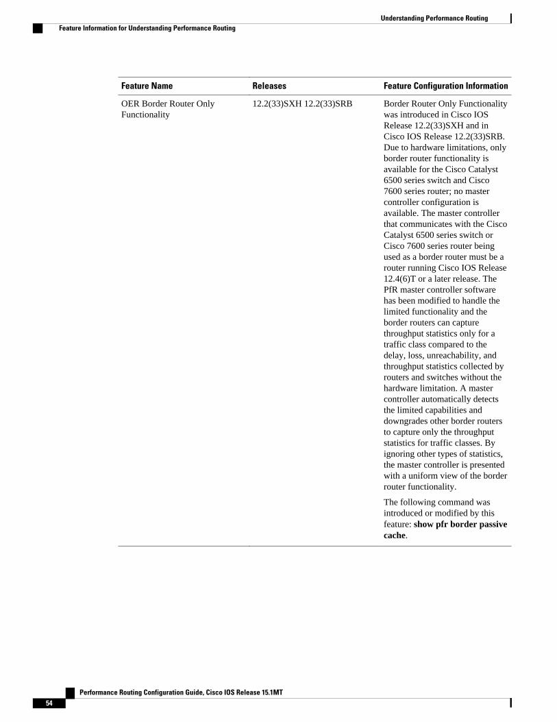
Feature Name Releases Feature Configuration Information
OER Border Router OnlyFunctionality
12.2(33)SXH 12.2(33)SRB Border Router Only Functionalitywas introduced in Cisco IOSRelease 12.2(33)SXH and inCisco IOS Release 12.2(33)SRB.Due to hardware limitations, onlyborder router functionality isavailable for the Cisco Catalyst6500 series switch and Cisco7600 series router; no mastercontroller configuration isavailable. The master controllerthat communicates with the CiscoCatalyst 6500 series switch orCisco 7600 series router beingused as a border router must be arouter running Cisco IOS Release12.4(6)T or a later release. ThePfR master controller softwarehas been modified to handle thelimited functionality and theborder routers can capturethroughput statistics only for atraffic class compared to thedelay, loss, unreachability, andthroughput statistics collected byrouters and switches without thehardware limitation. A mastercontroller automatically detectsthe limited capabilities anddowngrades other border routersto capture only the throughputstatistics for traffic classes. Byignoring other types of statistics,the master controller is presentedwith a uniform view of the borderrouter functionality.
The following command wasintroduced or modified by thisfeature: show pfr border passivecache.
Understanding Performance Routing Feature Information for Understanding Performance Routing
Performance Routing Configuration Guide, Cisco IOS Release 15.1MT54

Feature Name Releases Feature Configuration Information
OER Support for Policy-RulesConfiguration
12.3(11)T 12.2(33)SRB The OER Support for Policy-Rules Configuration featureintroduced the capability to selecta PfR map and apply theconfiguration under PfR mastercontroller configuration mode,providing an improved method toswitch between predefined PfRmaps.
The following commands wereintroduced or modified by thisfeature: policy-rules (PfR).
Support for Fast FailoverMonitoring2
12.4(15)T Fast Failover Monitoringintroduced the ability to configurea fast monitoring mode. In fastfailover monitoring mode, allexits are continuously probedusing active monitoring andpassive monitoring. The probefrequency can be set to a lowerfrequency in fast failovermonitoring mode than for othermonitoring modes, to allow afaster failover capability. Fastfailover monitoring can be usedwith all types of active probes:ICMP echo, jitter, TCPconnection, and UDP echo.
The following commands weremodified by this feature: mode(PfR), set mode (PfR).
Cisco and the Cisco Logo are trademarks of Cisco Systems, Inc. and/or its affiliates in the U.S. and othercountries. A listing of Cisco's trademarks can be found at www.cisco.com/go/trademarks. Third partytrademarks mentioned are the property of their respective owners. The use of the word partner does notimply a partnership relationship between Cisco and any other company. (1005R)
Any Internet Protocol (IP) addresses and phone numbers used in this document are not intended to beactual addresses and phone numbers. Any examples, command display output, network topology diagrams,and other figures included in the document are shown for illustrative purposes only. Any use of actual IPaddresses or phone numbers in illustrative content is unintentional and coincidental.
2 This is a minor enhancement. Minor enhancements are not typically listed in Feature Navigator.
Understanding Performance Routing
Performance Routing Configuration Guide, Cisco IOS Release 15.1MT 55

Verify Phase Concepts
Performance Routing Configuration Guide, Cisco IOS Release 15.1MT56

Configuring Advanced Performance Routing
After configuring the Performance Routing (PfR) master controller and border routers (see the"Configuring Basic Performance Routing" module), additional configuration is required to activate thefull optimization capabilities of PfR. Tasks and configuration examples that represent each of the PfRphases are documented here to help you learn how to configure and verify some of the advanced optionsfor each PfR phase.
Note The PfR configuration modules refer to the PfR syntax introduced in Cisco IOS Release 15.1(2)T. If youare running Cisco IOS Release 15.1(1)T, or an earlier release, or any 12.2SR or 12.2SX image, you needto consult the "Optimized Edge Routing Configuration Guide" module to help you locate all theOptimized Edge Routing documentation.
• Finding Feature Information, page 57• Prerequisites for Configuring Advanced Performance Routing, page 57• Information About Advanced Performance Routing, page 58• How to Configure Advanced Performance Routing, page 61• Configuration Examples for Advanced Performance Routing, page 106• Where to Go Next, page 116• Additional References, page 116• Feature Information for Configuring Advanced Performance Routing, page 117
Finding Feature InformationYour software release may not support all the features documented in this module. For the latest featureinformation and caveats, see the release notes for your platform and software release. To find informationabout the features documented in this module, and to see a list of the releases in which each feature issupported, see the Feature Information Table at the end of this document.
Use Cisco Feature Navigator to find information about platform support and Cisco software image support.To access Cisco Feature Navigator, go to www.cisco.com/go/cfn. An account on Cisco.com is not required.
Prerequisites for Configuring Advanced Performance Routing• This module requires the master controller and border routers to be running Cisco IOS Release
15.1(2)T, or later release.
Performance Routing Configuration Guide, Cisco IOS Release 15.1MT 57

• Before configuring the tasks in this module, you must configure a master controller and at least twoborder routers using the "Configuring Basic Performance Routing" module.
• Before configuring the tasks in this module, you must be familiar with the concepts contained in the"Understanding Performance Routing" module.
• Either routing protocol peering must be established on your network or static routing must beconfigured before route control mode is enabled.
If you have configured internal Border Gateway Protocol (iBGP) on the border routers, BGP peering mustbe either established and consistently applied throughout your network or redistributed into an InteriorGateway Protocol (IGP). The following IGPs are supported: Enhanced Interior Gateway Routing Protocol(EIGRP), Open Shortest Path First (OSPF), Intermediate System-to-Intermediate System (IS-IS), orRouting Information Protocol (RIP).
If an IGP is deployed in your network, static route redistribution must be configured with the redistributecommand unless iBGP is configured. IGP or static routing should also be applied consistently throughout aPfR-managed network; the border router should have a consistent view of the network.
Caution Caution must be applied when redistributing PfR static routes into an IGP. The routes injected by PfR maybe more specific than routes in the IGP, and it will appear as if the PfR border router is originating theseroutes. To avoid routing loops, the redistributed PfR static routes should never be advertised over a WANby a PfR border router or any other router. Route filtering and stub network configuration can be used toprevent advertising the PfR static routes. If the PfR static routes are redistributed to routers terminating thePfR external interfaces, routing loops may occur.
Information About Advanced Performance RoutingTo configure advanced PfR, you should understand the following concepts:
• Performance Routing Overview, page 2• Advanced Performance Routing Deployment, page 59• PfR Active Probing Target Reachability, page 61• ICMP Echo Probes, page 61• Jitter, page 61• MOS, page 61
Performance Routing OverviewPerformance Routing (PfR) is an advanced Cisco technology to allow businesses to complement classicrouting technologies with additional serviceability parameters to select the best egress or ingress path. Itcomplements these classic routing technologies with additional intelligence. PfR can select an egress oringress WAN interface based upon parameters like reachability, delay, cost, jitter, MOS score, or it can useinterface parameters like load, throughput and monetary cost. Classic routing (for example, EIGRP, OSPF,RIPv2, and BGP) generally focuses upon creating a loop-free topology based upon the shortest or least costpath.
PfR gains additional intelligence using measurement instrumentation. It uses interface statistics, Cisco IPSLA for active monitoring, and NetFlow for passive monitoring. No prior knowledge or experience of IPSLA or NetFlow is required, PfR automatically enables these technologies without any manualconfiguration.
Performance Routing Overview Information About Advanced Performance Routing
Performance Routing Configuration Guide, Cisco IOS Release 15.1MT58

Cisco Performance Routing selects an egress or ingress WAN path based on parameters that affectapplication performance, including reachability, delay, cost, jitter, and Mean Opinion Score (MOS). Thistechnology can reduce network costs by facilitating more efficient load balancing and by increasingapplication performance without WAN upgrades.
PfR is an integrated Cisco IOS solution that allows you to monitor IP traffic flows and then define policiesand rules based on traffic class performance, link load distribution, link bandwidth monetary cost, andtraffic type. PfR provides active and passive monitoring systems, dynamic failure detection, and automaticpath correction. Deploying PfR enables intelligent load distribution and optimal route selection in anenterprise network.
Advanced Performance Routing DeploymentAdvanced PfR is configured on Cisco routers using Cisco IOS command-line interface (CLI)configurations. The PfR infrastructure includes a performance routing protocol that is communicated in aclient-server messaging mode. The routing protocol employed by PfR runs between a network controllercalled a master controller and performance-aware devices called border routers. This performance routingprotocol creates a network performance loop in which the network profiles which traffic classes have to beoptimized, measures and monitors the performance metrics of the identified traffic classes, applies policiesto the traffic classes, and routes the identified traffic classes based on the best performance path.
The PfR performance loop starts with the profile phase followed by the measure, apply policy, control, andverify phases. The flow continues after the verify phase back to the profile phase to update the trafficclasses and cycle through the process.
Advanced PfR requires configuring tasks to address each of the following PfR Phases:
• Profile Phase, page 7• Measure Phase, page 7• Apply Policy Phase, page 8• Enforce Phase, page 8• Verify Phase, page 8
Profile PhaseIn medium to large networks there are hundreds of thousands of routes in the RIB to which a device istrying to route traffic. Because performance routing is a means of preferring some traffic over another, asubset of the total routes in the RIB has to be selected to optimize for performance routing. PfR profilestraffic in one of two ways, automatic learning or manual configuration.
• Automatic Learning—The device profiles the traffic that has to be performance routed (optimized) bylearning the flows that pass through the device and by selecting those flows that have the highest delayor the highest throughput.
• Manual configuration—In addition to, or instead of learning, you can configure a class of traffic toperformance route.
Measure PhaseAfter profiling traffic classes that are to be performance routed, PfR measures the performance metrics ofthese individual traffic classes. There are two mechanisms--passive monitoring and active monitoring--tomeasure performance metrics, and one or both could be deployed in the network to accomplish this task.Monitoring is the act of measuring at periodic intervals.
Passive monitoring is the act of measuring the performance metrics of the traffic flow as the flow istraversing the device in the data path. Passive monitoring uses NetFlow functionality and cannot be
Advanced Performance Routing DeploymentProfile Phase
Performance Routing Configuration Guide, Cisco IOS Release 15.1MT 59

employed for measuring performance metrics for some traffic classes, and there are some hardware orsoftware limitations.
Active monitoring consists of generating synthetic traffic using IP Service Level Agreements (SLAs) toemulate the traffic class that is being monitored. The synthetic traffic is measured instead of the actualtraffic class. The results of the synthetic traffic monitoring are applied to performance route the traffic classrepresented by the synthetic traffic.
Both passive and active monitoring modes can be applied to the traffic classes. The passive monitoringphase may detect traffic class performance that does not conform to an PfR policy, and then activemonitoring can be applied to that traffic class to find the best alternate performance path, if available.
Support for NetFlow or IP SLAs configuration is enabled automatically.
Apply Policy PhaseAfter collecting the performance metrics of the class of traffic to be optimized, PfR compares the resultswith a set of configured low and high thresholds for each metric configured as a policy. When a metric, andconsequently a policy, goes out of bounds, it is an Out-of-Policy (OOP) event. The results are compared ona relative basis--a deviation from the observed mean--or on a threshold basis--the lower or upper bounds ofa value--or a combination of both.
There are two types of policies that can be defined in PfR: traffic class policies and link policies. Trafficclass policies are defined for prefixes or for applications. Link policies are defined for exit or entrance linksat the network edge. Both types of PfR policies define the criteria for determining an OOP event. Thepolicies are applied on a global basis in which a set of policies is applied to all traffic classes, or on a moretargeted basis in which a set of policies is applied to a selected (filtered) list of traffic classes.
With multiple policies, many performance metric parameters, and different ways of assigning these policiesto traffic classes, a method of resolving policy conflicts was created. The default arbitration method uses adefault priority level given to each performance metric variable and each policy. Different priority levelscan be configured to override the default arbitration for all policies, or a selected set of policies.
Enforce PhaseIn the PfR enforce phase (also called the control phase) of the performance loop, the traffic is controlled toenhance the performance of the network. The technique used to control the traffic depends on the class oftraffic. For traffic classes that are defined using a prefix only, the prefix reachability information used intraditional routing can be manipulated. Protocols such as Border Gateway Protocol (BGP) or RIP are usedto announce or remove the prefix reachability information by introducing or deleting a route and itsappropriate cost metrics.
For traffic classes that are defined by an application in which a prefix and additional packet matchingcriteria are specified, PfR cannot employ traditional routing protocols because routing protocolscommunicate the reachability of the prefix only and the control becomes device specific and not networkspecific. This device specific control is implemented by PfR using policy-based routing (PBR)functionality. If the traffic in this scenario has to be routed out to a different device, the remote borderrouter should be a single hop away or a tunnel interface that makes the remote border router look like asingle hop.
Verify PhaseDuring the PfR enforce phase if a traffic class is OOP, then PfR introduces controls to influence (optimize)the flow of the traffic for the traffic class that is OOP. A static route and a BGP route are examples ofcontrols introduced by PfR into the network. After the controls are introduced, PfR will verify that the
Configuring Advanced Performance Routing Apply Policy Phase
Performance Routing Configuration Guide, Cisco IOS Release 15.1MT60

optimized traffic is flowing through the preferred exit or entrance links at the network edge. If the trafficclass remains OOP, PfR will drop the controls that were introduced to optimize the traffic for the OOPtraffic class and cycle through the network performance loop.
PfR Active Probing Target ReachabilityThe active probe is sourced from the border router and transmitted through an external interface (theexternal interface may or may not be the preferred route for an optimized prefix). When creating an activeprobe through an external interface for a specified target, the target should be reachable through theexternal interface. To test the reachability of the specified target, PfR performs a route lookup in the BGPand static routing tables for the specified target and external interface.
ICMP Echo ProbesConfiguring an ICMP echo probe does not require knowledgeable cooperation from the target device.However, repeated probing could trigger an IDS alarm in the target network. If an IDS is configured in atarget network that is not under your administrative control, we recommend that you notify the targetnetwork administration entity.
The following defaults are applied when active monitoring is enabled:
• The border router collects up to five host addresses from the traffic class for active probing when atraffic class is learned or aggregated.
• Active probes are sent once per minute.• ICMP probes are used to actively monitor learned traffic classes.
JitterJitter means interpacket delay variance. When multiple packets are sent consecutively from source todestination, for example, 10 ms apart, and if the network is behaving ideally, the destination should bereceiving them 10 ms apart. But if there are delays in the network (like queuing, arriving through alternateroutes, and so on) the arrival delay between packets might be greater than or less than 10 ms. Using thisexample, a positive jitter value indicates that the packets arrived more than 10 ms apart. If the packetsarrive 12 ms apart, then positive jitter is 2 ms; if the packets arrive 8 ms apart, then negative jitter is 2 ms.For delay-sensitive networks like VoIP, positive jitter values are undesirable, and a jitter value of 0 is ideal.
MOSMean Opinion Score (MOS) is a quantitative quality metric for voice traffic that can be measured usingPfR active probes. With all the factors affecting voice quality, many people ask how voice quality can bemeasured. Standards bodies like the ITU have derived two important recommendations: P.800 (MOS) andP.861 (Perceptual Speech Quality Measurement [PSQM]). P.800 is concerned with defining a method toderive a Mean Opinion Score of voice quality. MOS scores range between 1 representing the worst voicequality, and 5 representing the best voice quality. A MOS of 4 is considered "toll-quality" voice.
How to Configure Advanced Performance RoutingThis section contains the following tasks:
• Profiling Phase Tasks, page 62• Measuring Phase Tasks, page 70
PfR Active Probing Target ReachabilityHow to Configure Advanced Performance Routing
Performance Routing Configuration Guide, Cisco IOS Release 15.1MT 61

• Apply Policy Phase Tasks, page 88
• Enforce Phase Tasks, page 101
• Verify Phase Task, page 104
Profiling Phase TasksThe following tasks show how to configure elements of the PfR profiling phase:
• Defining a Learn List for Automatically Learned Application Traffic Classes Using an Access List, page 62
• Manually Selecting Prefix-Based Traffic Classes Using a Prefix List, page 66
• Displaying and Resetting Traffic Class and Learn List Information, page 68
Defining a Learn List for Automatically Learned Application Traffic Classes Using anAccess List
Perform this task at the master controller to define a learn list that will contain traffic classes that areautomatically learned by PfR using an access list to create customized application traffic classes. In thistask, an access list is created that defines custom application traffic classes. Every entry in the access listdefines one application. A learn list is then defined, the access list is applied, and an aggregation method isconfigured. Using the count (PfR) command, 50 traffic classes can be learned during one learning sessionfor the learn list named LEARN_USER_DEFINED_TC, with a maximum specified number of 90 trafficclasses for this learn list. The master controller is configured to learn the top prefixes based on highestdelay for the filtered traffic and the resulting traffic classes are added to the PfR application database.
A learn list is activated using a PfR map and the last few steps in this task demonstrate how to configure aPfR map to activate the learn list defined in this task and create the custom traffic class.
For an example of defining a learn list for automatically learned prefix-based traffic classes using a prefixlist, see the “Example: Defining a Learn List for Automatically Learned Prefix-Based Traffic Classes”section.
Profiling Phase Tasks Defining a Learn List for Automatically Learned Application Traffic Classes Using an Access List
Performance Routing Configuration Guide, Cisco IOS Release 15.1MT62

SUMMARY STEPS
1. enable
2. configure terminal
3. ip access-list {standard | extended} access-list-name
4. [sequence-number] permit udp source source-wildcard [operator [port]] destination destination-wildcard [operator [port]] [dscp dscp-value]
5. Repeat Step 4 for more access list entries, as required.
6. exit
7. pfr master
8. learn
9. list seq number refname refname
10. count number max max-number
11. traffic-class access-list access-list-name [filter prefix-list-name]
12. aggregation-type {bgp non-bgp prefix-length} prefix-mask
13. delay
14. exit
15. Repeat Step 14 twice to return to global configuration mode.
16. pfr-map map-name sequence-number
17. match traffic-class access -list access-list-name
18. end
DETAILED STEPS
Command or Action Purpose
Step 1 enable
Example:
Router> enable
Enables privileged EXEC mode.
• Enter your password if prompted.
Step 2 configure terminal
Example:
Router# configure terminal
Enters global configuration mode.
Step 3 ip access-list {standard | extended}access-list-name
Example:
Router(config)# ip access-list extended USER_DEFINED_TC
Defines an IP access list by name.
• PfR supports only named access lists.• The example creates an extended IP access list named
USER_DEFINED_TC.
Configuring Advanced Performance RoutingDefining a Learn List for Automatically Learned Application Traffic Classes Using an Access List
Performance Routing Configuration Guide, Cisco IOS Release 15.1MT 63

Command or Action Purpose
Step 4 [sequence-number] permit udp sourcesource-wildcard [operator [port]]destination destination-wildcard[operator [port]] [dscp dscp-value]
Example:
Router(config-ext-nacl)# permit tcp any any 500
Sets conditions to allow a packet to pass a named IP access list.
• The example is configured to identify all TCP traffic from anydestination or source and from destination port number of 500. Thisspecific TCP traffic is to be optimized.
Note Only the syntax applicable to this task is shown. For more details, seethe Cisco IOS IP Application Services Command Reference.
Step 5 Repeat Step 4 for more access listentries, as required.
--
Step 6 exit
Example:
Router(config-ext-nacl)# exit
(Optional) Exits extended access list configuration mode and returns to globalconfiguration mode.
Step 7 pfr master
Example:
Router(config)# pfr master
Enters PfR master controller configuration mode to configure a Cisco routeras a master controller and to configure master controller policy and timersettings.
Step 8 learn
Example:
Router(config-pfr-mc)# learn
Enters PfR Top Talker and Top Delay learning configuration mode toautomatically learn traffic classes.
Step 9 list seq number refname refname
Example:
Router(config-pfr-mc-learn)# list seq 10 refname LEARN_USER_DEFINED_TC
Creates an PfR learn list and enters learn list configuration mode.
• Use the seq keyword and number argument to specify a sequencenumber used to determine the order in which learn list criteria is applied.
• Use the refname keyword and refname argument to specify a referencename for the learn list.
• The example creates a learn list named LEARN_USER_DEFINED_TC.
Configuring Advanced Performance Routing Defining a Learn List for Automatically Learned Application Traffic Classes Using an Access List
Performance Routing Configuration Guide, Cisco IOS Release 15.1MT64

Command or Action Purpose
Step 10 count number max max-number
Example:
Router(config-pfr-mc-learn-list)# count 50 max 90
Sets the number of traffic classes to be learned during an PfR learn session.
• Use the number argument to specify a number of traffic classes to belearned for the specified learn list during a learn session.
• Use the max keyword and max-number argument to specify a maximumnumber of traffic classes to be learned for the specified learn list duringall learning sessions.
• The example specifies 50 traffic classes to be learned per learningsession for the learn list named LEARN_USER_DEFINED_TC, and amaximum of 90 traffic classes in total for this learn list.
Step 11 traffic-class access-list access-list-name[filter prefix-list-name]
Example:
Router(config-pfr-mc-learn-list)# traffic-class access-list USER_DEFINED_TC
Defines a PfR traffic class using an access list.
• Use the access-list-name argument to specify an access list that containscriteria for defining the traffic classes.
• The example uses the access list named USER_DEFINED_TC to createthe traffic classes.
Step 12 aggregation-type {bgp non-bgp prefix-length} prefix-mask
Example:
Router(config-pfr-mc-learn-list)# aggregation-type prefix-length 24
(Optional) Configures a master controller to aggregate learned prefixes basedon traffic flow type.
• The bgp keyword configures prefix aggregation based on entries in theBGP routing table. This keyword is used if BGP peering is enabled in thenetwork.
• The non-bgp keyword configures learned prefix aggregation based onstatic routes. Entries in the BGP routing table are ignored when thiskeyword is entered.
• The prefix-length keyword configures aggregation based on thespecified prefix length. The range of values that can be configured forthis argument is a prefix mask from 1 to 32.
• If this command is not specified, the default aggregation is performedbased on a /24 prefix length.
• The example configures prefix length aggregation based on a /24 prefixlength.
Step 13 delay
Example:
Router(config-pfr-mc-learn-list)# delay
Enables prefix learning based on the highest delay time.
• Top Delay prefixes are sorted from the highest to lowest delay time.• The example configures prefix learning based on the highest delay.
Note To configure automatic PfR learning within a learn list you can specifyeither the delay (PfR) command or the throughput (PfR) command,but they are mutually exclusive in learn list configuration mode.
Configuring Advanced Performance RoutingDefining a Learn List for Automatically Learned Application Traffic Classes Using an Access List
Performance Routing Configuration Guide, Cisco IOS Release 15.1MT 65
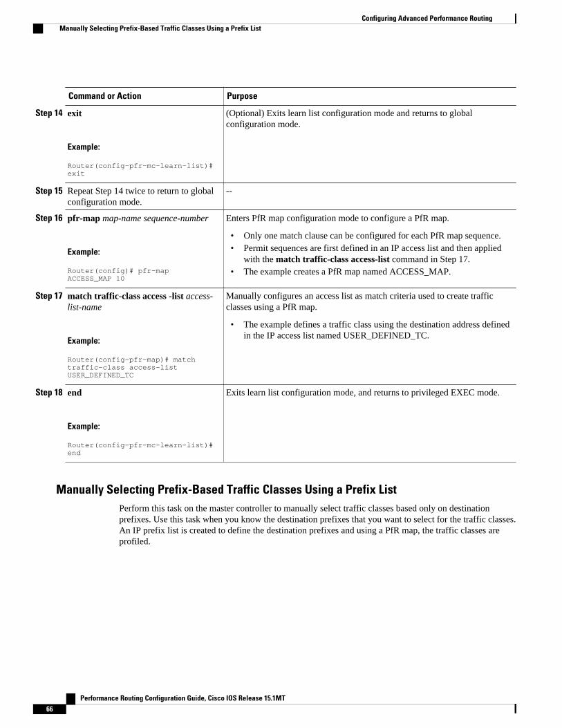
Command or Action Purpose
Step 14 exit
Example:
Router(config-pfr-mc-learn-list)# exit
(Optional) Exits learn list configuration mode and returns to globalconfiguration mode.
Step 15 Repeat Step 14 twice to return to globalconfiguration mode.
--
Step 16 pfr-map map-name sequence-number
Example:
Router(config)# pfr-map ACCESS_MAP 10
Enters PfR map configuration mode to configure a PfR map.
• Only one match clause can be configured for each PfR map sequence.• Permit sequences are first defined in an IP access list and then applied
with the match traffic-class access-list command in Step 17.• The example creates a PfR map named ACCESS_MAP.
Step 17 match traffic-class access -list access-list-name
Example:
Router(config-pfr-map)# match traffic-class access-list USER_DEFINED_TC
Manually configures an access list as match criteria used to create trafficclasses using a PfR map.
• The example defines a traffic class using the destination address definedin the IP access list named USER_DEFINED_TC.
Step 18 end
Example:
Router(config-pfr-mc-learn-list)# end
Exits learn list configuration mode, and returns to privileged EXEC mode.
Manually Selecting Prefix-Based Traffic Classes Using a Prefix ListPerform this task on the master controller to manually select traffic classes based only on destinationprefixes. Use this task when you know the destination prefixes that you want to select for the traffic classes.An IP prefix list is created to define the destination prefixes and using a PfR map, the traffic classes areprofiled.
Configuring Advanced Performance Routing Manually Selecting Prefix-Based Traffic Classes Using a Prefix List
Performance Routing Configuration Guide, Cisco IOS Release 15.1MT66

SUMMARY STEPS
1. enable
2. configure terminal
3. ip prefix-list list-name [seq seq-value] {deny network/length | permit network/length}
4. Repeat Step 3 for more prefix list entries, as required.
5. pfr-map map-name sequence-number
6. match traffic-class prefix-list prefix-list-name
7. end
DETAILED STEPS
Command or Action Purpose
Step 1 enable
Example:
Router> enable
Enables privileged EXEC mode.
• Enter your password if prompted.
Step 2 configure terminal
Example:
Router# configure terminal
Enters global configuration mode.
Step 3 ip prefix-list list-name [seq seq-value] {denynetwork/length | permit network/length}
Example:
Router(config)# ip prefix-list PREFIX_TC permit 172.16.1.0/24
Creates a prefix list to specify destination prefix-based traffic classes.
• The example creates a prefix list named PREFIX_TC thatspecifies a destination prefix of 172.16.1.0/24 to be selected for atraffic class.
Step 4 Repeat Step 3 for more prefix list entries, asrequired.
--
Step 5 pfr-map map-name sequence-number
Example:
Router(config)# pfr-map PREFIX_MAP 10
Enters PfR map configuration mode to configure a PfR map.
• Only one match clause can be configured for each PfR mapsequence.
• Permit sequences are first defined in an IP prefix list and thenapplied with the match traffic-class prefix-list command in Step6.
• The example creates a PfR map named PREFIX_MAP.
Configuring Advanced Performance RoutingManually Selecting Prefix-Based Traffic Classes Using a Prefix List
Performance Routing Configuration Guide, Cisco IOS Release 15.1MT 67

Command or Action Purpose
Step 6 match traffic-class prefix-list prefix-list-name
Example:
Router(config-pfr-map)# match traffic-class prefix-list PREFIX_TC
Manually configures a prefix list as match criteria used to create trafficclasses using a PfR map.
• The example defines a traffic class using the destination addressdefined in the IP prefix list named PREFIX_TC.
Step 7 end
Example:
Router(config-pfr-map)# end
(Optional) Exits PfR map configuration mode and returns to privilegedEXEC mode.
Displaying and Resetting Traffic Class and Learn List InformationPerform this task to display traffic class and learn list information and optionally, to reset some traffic classinformation. These commands can be entered on a master controller after learn lists are configured andtraffic classes are automatically learned, or when traffic classes are manually configured using a PfR map.The commands can be entered in any order and all the commands are optional.
SUMMARY STEPS
1. enable
2. show pfr master traffic-class [access-list access-list-name| application application-name[prefix] |inside | learned[delay | inside | list list-name| throughput] | prefix prefix| prefix-list prefix-list-name][active| passive| status] [detail]
3. show pfr master learn list [list-name]
4. clear pfr master traffic-class [access-list access-list-name| application application-name[prefix]|inside | learned[delay | inside | list list-name| throughput]| prefix prefix| prefix-list prefix-list-name]
DETAILED STEPS
Step 1 enableEnables privileged EXEC mode. Enter your password if prompted.
Example:
Router> enable
Step 2 show pfr master traffic-class [access-list access-list-name| application application-name[prefix] | inside |learned[delay | inside | list list-name| throughput] | prefix prefix| prefix-list prefix-list-name] [active| passive|status] [detail]This command is used to display information about traffic classes learned or manually configured under PfR learn listconfiguration mode.
Configuring Advanced Performance Routing Displaying and Resetting Traffic Class and Learn List Information
Performance Routing Configuration Guide, Cisco IOS Release 15.1MT68

Example:
Router# show pfr master traffic-class
OER Prefix Statistics: Pas - Passive, Act - Active, S - Short term, L - Long term, Dly - Delay (ms), P - Percentage below threshold, Jit - Jitter (ms), MOS - Mean Opinion Score Los - Packet Loss (packets-per-million), Un - Unreachable (flows-per-million), E - Egress, I - Ingress, Bw - Bandwidth (kbps), N - Not applicable U - unknown, * - uncontrolled, + - control more specific, @ - active probe all # - Prefix monitor mode is Special, & - Blackholed Prefix % - Force Next-Hop, ^ - Prefix is denied DstPrefix Appl_ID Dscp Prot SrcPort DstPort SrcPrefix Flags State Time CurrBR CurrI/F Protocol PasSDly PasLDly PasSUn PasLUn PasSLos PasLLos EBw IBw ActSDly ActLDly ActSUn ActLUn ActSJit ActPMOS--------------------------------------------------------------------------------10.1.1.0/24 N defa N N N N # OOPOLICY 32 10.11.1.3 Gi0/0/0 BGP N N N N N N N IBwN 130 134 0 0 N N
Step 3 show pfr master learn list [list-name]This command is used to display one or all of the configured PfR learn lists. In this example, the information abouttwo learn lists is displayed.
Example:
Router# show pfr master learn list
Learn-List LIST1 10 Configuration: Application: ftp Aggregation-type: bgp Learn type: thruput Policies assigned: 8 10 Stats: Application Count: 0 Application Learned: Learn-List LIST2 20 Configuration: Application: telnet Aggregation-type: prefix-length 24 Learn type: thruput Policies assigned: 5 20 Stats: Application Count: 2 Application Learned: Appl Prefix 10.1.5.0/24 telnet Appl Prefix 10.1.5.16/28 telnet
Step 4 clear pfr master traffic-class [access-list access-list-name| application application-name[prefix]| inside |learned[delay | inside | list list-name| throughput]| prefix prefix| prefix-list prefix-list-name]This command is used to clear PfR controlled traffic classes from the master controller database. The followingexample clears traffic classes defined by the Telnet application and the 10.1.1.0/24 prefix:
Example:
Router# clear pfr master traffic-class application telnet 10.1.1.0/24
Configuring Advanced Performance RoutingDisplaying and Resetting Traffic Class and Learn List Information
Performance Routing Configuration Guide, Cisco IOS Release 15.1MT 69

Measuring Phase TasksThe following tasks show how to configure elements of the PfR measure phase:
• Modifying the PfR Link Utilization for Outbound Traffic, page 70
• Modifying the PfR Exit Link Utilization Range, page 72
• Configuring and Verifying PfR Passive Monitoring, page 73
• Configuring PfR Active Probing Using the Longest Match Target Assignment, page 75
• Configuring PfR Voice Probes with a Forced Target Assignment, page 77
• Configuring PfR Voice Probes for Fast Failover, page 81
• Configuring the Source Address of an Active Probe, page 86
Modifying the PfR Link Utilization for Outbound TrafficPerform this task at the master controller to modify the PfR exit (outbound) link utilization threshold. Afteran external interface has been configured for a border router, PfR automatically monitors the utilization ofexternal links on a border router every 20 seconds. The utilization is reported back to the master controllerand, if the utilization exceeds 75 percent, PfR selects another exit link for traffic classes on that link. Anabsolute value in kilobytes per second (kbps), or a percentage, can be specified.
For more details about the configuration of measuring inbound traffic, see the “BGP Inbound OptimizationUsing Performance Routing” module.
SUMMARY STEPS
1. enable
2. configure terminal
3. pfr master
4. border ip-address [key-chain key-chain-name]
5. interface type number external
6. max-xmit-utilization {absolute kbps | percentage value
7. end
DETAILED STEPS
Command or Action Purpose
Step 1 enable
Example:
Router> enable
Enables privileged EXEC mode.
• Enter your password if prompted.
Step 2 configure terminal
Example:
Router# configure terminal
Enters global configuration mode.
Measuring Phase Tasks Modifying the PfR Link Utilization for Outbound Traffic
Performance Routing Configuration Guide, Cisco IOS Release 15.1MT70

Command or Action Purpose
Step 3 pfr master
Example:
Router(config)# pfr master
Enters PfR master controller configuration mode to configure a router as a mastercontroller and to configure global operations and policies.
Step 4 border ip-address [key-chain key-chain-name]
Example:
Router(config-pfr-mc)# border 10.1.1.2
Enters PfR-managed border router configuration mode to establishcommunication with a border router.
• An IP address is configured to identify the border router.• At least one border router must be specified to create a PfR-managed
network. A maximum of ten border routers can be controlled by a singlemaster controller.
Note The key-chain keyword and key-chain-name argument must be enteredwhen a border router is initially configured. However, this keyword isoptional when reconfiguring an existing border router.
Step 5 interface type number external
Example:
Router(config-pfr-mc-br)# interface Ethernet 1/0 external
Configures a border router interface as a PfR-managed external interface andenters PfR border exit interface configuration mode.
• External interfaces are used to forward traffic and for active monitoring.• A minimum of two external border router interfaces are required in a PfR-
managed network. At least one external interface must be configured on eachborder router. A maximum of 20 external interfaces can be controlled bysingle master controller.
Note Entering the interface (PfR) command without the external orinternalkeyword places the router in global configuration mode and not PfR borderexit configuration mode. The no form of this command should be appliedcarefully so that active interfaces are not removed from the routerconfiguration.
Step 6 max-xmit-utilization {absolute kbps| percentage value
Example:
Router(config-pfr-mc-br-if)# max-xmit-utilization absolute 500000
Configures the maximum utilization on a single PfR managed exit link.
• Use the absolute keyword and kbps argument to specify the absolutemaximum utilization on a PfR managed exit link in kbps.
• Use the percentage keyword and value argument to specify percentageutilization of an exit link.
Step 7 end
Example:
Router(config-pfr-mc-br-if)# end
Exits PfR border exit interface configuration mode and returns to privilegedEXEC mode.
Configuring Advanced Performance RoutingModifying the PfR Link Utilization for Outbound Traffic
Performance Routing Configuration Guide, Cisco IOS Release 15.1MT 71

Modifying the PfR Exit Link Utilization RangePerform this task at the master controller to modify the maximum exit link utilization range threshold overall the border routers. By default, PfR automatically monitors the utilization of external links on a borderrouter every 20 seconds, and the border router reports the utilization to the master controller. If theutilization range between all the exit links exceeds 20 percent, the master controller tries to equalize thetraffic load by moving some traffic classes to another exit link. The maximum utilization range isconfigured as a percentage.
PfR uses the maximum utilization range to determine if exit links are in-policy. PfR will equalize outboundtraffic across all exit links by moving traffic classes from overutilized or out-of-policy exits to in-policyexits.
Note If you are configuring link grouping, configure the no max-range-utilization command because using alink utilization range is not compatible with using a preferred or fallback set of exit links configured forlink grouping.
For more details about the configuration of measuring inbound traffic, see the “BGP Inbound OptimizationUsing Performance Routing” module.
SUMMARY STEPS
1. enable
2. configure terminal
3. pfr master
4. max-range-utilization percent maximum
5. end
DETAILED STEPS
Command or Action Purpose
Step 1 enable
Example:
Router> enable
Enables privileged EXEC mode.
• Enter your password if prompted.
Step 2 configure terminal
Example:
Router# configure terminal
Enters global configuration mode.
Configuring Advanced Performance Routing Modifying the PfR Exit Link Utilization Range
Performance Routing Configuration Guide, Cisco IOS Release 15.1MT72

Command or Action Purpose
Step 3 pfr master
Example:
Router(config)# pfr master
Enters PfR master controller configuration mode to configure a routeras a master controller and to configure global operations and policies.
Step 4 max-range-utilization percent maximum
Example:
Router(config-pfr-mc)# max-range-utilization percent 25
Sets the maximum utilization range for all PfR-managed exit link.s.
• Use the percent keyword and maximum argument to specify themaximum utilization range between all the exit links.
• In this example, the utilization range between all the exit links onthe border routers must be within 25 percent.
Step 5 end
Example:
Router(config-pfr-mc)# end
Exits PfR master controller configuration mode and returns toprivileged EXEC mode.
Configuring and Verifying PfR Passive MonitoringPfR enables passive monitoring by default when a PfR managed network is created, but there are timeswhen passive monitoring is disabled. Use this task to configure passive monitoring and then verify that thepassive monitoring is being performed. Perform the first five steps on a master controller and then move toa border router to display passive measurement information collected by NetFlow for monitored prefixes orapplication traffic flows. The show commands are entered on a border router through which the applicationtraffic is flowing. The show commands can be entered in any order.
SUMMARY STEPS
1. enable
2. configure terminal
3. pfr master
4. mode monitor {active | both| fast| passive}
5. end
6. Move to one of the border routers.
7. enable
8. show pfr border passive cache {learned[application| traffic-class]}
9. show pfr border passive prefixes
DETAILED STEPS
Step 1 enableEnables privileged EXEC mode. Enter your password if prompted.
Configuring Advanced Performance RoutingConfiguring and Verifying PfR Passive Monitoring
Performance Routing Configuration Guide, Cisco IOS Release 15.1MT 73

Example:
Router> enable
Step 2 configure terminalEnters global configuration mode.
Example:
Router# configure terminal
Step 3 pfr masterEnters PfR master controller configuration mode to configure a router as a master controller and to configure globaloperations and policies.
Example:
Router(config)# pfr master
Step 4 mode monitor {active | both| fast| passive}Configures route monitoring or route control on a PfR master controller. The monitor keyword is used to configureactive monitoring, passive monitoring, or both active and passive monitoring. Passive monitoring is enabled wheneither the both or passive keywords are specified. In this example, passive monitoring is enabled.
Example:
Router(config-pfr-mc)# mode monitor passive
Step 5 endExits PfR master controller configuration mode and returns to privileged EXEC mode.
Example:
Router(config-pfr-mc)# end
Step 6 Move to one of the border routers.Step 7 enable
Enables privileged EXEC mode. Enter your password if prompted.
Example:
Router> enable
Step 8 show pfr border passive cache {learned[application| traffic-class]}This command is used to display real-time passive measurement information collected by NetFlow from the borderrouter for PfR monitored prefixes and traffic flows. The following example uses the learned and application keywordsto display measurement information about monitored application traffic classes that have been learned by PfR. In thisexample for voice traffic, the voice application traffic is identified by the User Datagram Protocol (UDP) protocol, aDSCP value of ef, and port numbers in the range from 3000 to 4000.
Example:
Router# show pfr border passive cache learned application
Configuring Advanced Performance Routing Configuring and Verifying PfR Passive Monitoring
Performance Routing Configuration Guide, Cisco IOS Release 15.1MT74

OER Learn Cache: State is enabled Measurement type: throughput, Duration: 2 min Aggregation type: prefix-length, Prefix length: 24 4096 oer-flows per chunk, 8 chunks allocated, 32 max chunks, 5 allocated records, 32763 free records, 4588032 bytes allocatedPrefix Mask Pkts B/Pk Delay Samples ActiveProt Dscp SrcPort DstPort Host1 Host2 Host3 Host4 Host5 dport1 dport2 dport3 dport4 dport510.1.3.0 /24 873 28 0 0 13.3 17 ef [1, 65535] [3000, 4000] 10.1.3.1 0.0.0.0 0.0.0.0 0.0.0.0 0.0.0.0 3500 0 0 0 0 10.1.1.0 /24 7674 28 0 0 13.4 17 ef [1, 65535] [3000, 4000] 10.1.1.1 0.0.0.0 0.0.0.0 0.0.0.0 0.0.0.0 3600 0 0 0 0
Step 9 show pfr border passive prefixesThis command is used to display passive measurement information collected by NetFlow for PfR monitored prefixesand traffic flows. The following output shows the prefix that is being passively monitored by NetFlow for the borderrouter on which the show pfr border passive prefixes command was run:
Example:
Router# show pfr border passive prefixesOER Passive monitored prefixes:Prefix Mask Match Type10.1.5.0 /24 exact
Configuring PfR Active Probing Using the Longest Match Target AssignmentPerform this task at the master controller to configure active probing using the longest match targetassignment. Active monitoring is enabled with the mode monitor activeormode monitor both commands,and the type of active probe is specified using the active-probe (PfR) command. Active probes areconfigured with a specific host or target address and the active probes are sourced on the border router. Theactive probe source external interface may, or may not, be the preferred route for an optimized prefix. Inthis example, both active and passive monitoring are enabled and the target IP address of 10.1.5.1 is to beactively monitored using Internet Control Message Protocol (ICMP) echo (ping) messages. This task doesnot require an IP SLA responder to be enabled.
SUMMARY STEPS
1. enable
2. configure terminal
3. pfr master
4. mode monitor {active | both | passive}
5. active-probe {echo ip-address | tcp-conn ip-address target-port number | udp-echo ip-addresstarget-port number}
6. end
Configuring Advanced Performance RoutingConfiguring PfR Active Probing Using the Longest Match Target Assignment
Performance Routing Configuration Guide, Cisco IOS Release 15.1MT 75

DETAILED STEPS
Command or Action Purpose
Step 1 enable
Example:
Router> enable
Enables privileged EXEC mode.
• Enter your password if prompted.
Step 2 configure terminal
Example:
Router# configure terminal
Enters global configuration mode.
Step 3 pfr master
Example:
Router(config)# pfr master
Enters PfR master controller configuration mode to configure a router as amaster controller and to configure global operations and policies.
Step 4 mode monitor {active | both | passive}
Example:
Router(config-pfr-mc)# mode monitor both
Configures route monitoring on a PfR master controller.
• The monitor keyword is used to configure active and/or passivemonitoring.
• The example enables both active and passive monitoring.
Step 5 active-probe {echo ip-address | tcp-connip-address target-port number | udp-echoip-address target-port number}
Example:
Router(config-pfr-mc)# active-probe echo 10.1.5.1
Configures an active probe for a target prefix.
• Active probing measures delay and jitter of the target prefix moreaccurately than is possible with only passive monitoring.
• Active probing requires you to configure a specific host or targetaddress.
• Active probes are sourced from a PfR managed external interfaces.This external interface may or may not be the preferred route for anoptimized prefix.
• A remote responder with the corresponding port number must beconfigured on the target device when configuring UDP echo probe orwhen configuring a TCP connection probe that is configured with aport number other than 23. The remote responder is configured with theip sla monitor responder global configuration command.
Step 6 end
Example:
Router(config-pfr-mc)# end
Exits PfR master controller configuration mode and returns to privilegedEXEC mode.
Configuring Advanced Performance Routing Configuring PfR Active Probing Using the Longest Match Target Assignment
Performance Routing Configuration Guide, Cisco IOS Release 15.1MT76
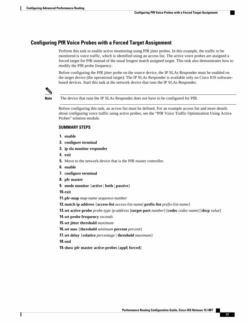
Configuring PfR Voice Probes with a Forced Target AssignmentPerform this task to enable active monitoring using PfR jitter probes. In this example, the traffic to bemonitored is voice traffic, which is identified using an access list. The active voice probes are assigned aforced target for PfR instead of the usual longest match assigned target. This task also demonstrates how tomodify the PfR probe frequency.
Before configuring the PfR jitter probe on the source device, the IP SLAs Responder must be enabled onthe target device (the operational target). The IP SLAs Responder is available only on Cisco IOS software-based devices. Start this task at the network device that runs the IP SLAs Responder.
Note The device that runs the IP SLAs Responder does not have to be configured for PfR.
Before configuring this task, an access list must be defined. For an example access list and more detailsabout configuring voice traffic using active probes, see the “PfR Voice Traffic Optimization Using ActiveProbes” solution module.
SUMMARY STEPS
1. enable
2. configure terminal
3. ip sla monitor responder
4. exit
5. Move to the network device that is the PfR master controller.
6. enable
7. configure terminal
8. pfr master
9. mode monitor {active | both | passive}
10. exit
11. pfr-map map-name sequence-number
12. match ip address {access-list access-list-name| prefix-list prefix-list-name}
13. set active-probe probe-type ip-address [target-port number] [codec codec-name] [dscp value]
14. set probe frequency seconds
15. set jitter threshold maximum
16. set mos {threshold minimum percent percent}
17. set delay {relative percentage | threshold maximum}
18. end
19. show pfr master active-probes [appl| forced]
Configuring Advanced Performance RoutingConfiguring PfR Voice Probes with a Forced Target Assignment
Performance Routing Configuration Guide, Cisco IOS Release 15.1MT 77

DETAILED STEPS
Command or Action Purpose
Step 1 enable
Example:
Router> enable
Enables privileged EXEC mode.
• Enter your password if prompted.
Step 2 configure terminal
Example:
Router# configure terminal
Enters global configuration mode.
Step 3 ip sla monitor responder
Example:
Router(config)# ip sla monitor responder
Enables the IP SLAs Responder.
Step 4 exit
Example:
Router(config)# exit
Exits global configuration mode and returns to privileged EXEC mode.
Step 5 Move to the network device that is thePfR master controller.
--
Step 6 enable
Example:
Router> enable
Enables privileged EXEC mode.
• Enter your password if prompted.
Step 7 configure terminal
Example:
Router# configure terminal
Enters global configuration mode.
Step 8 pfr master
Example:
Router(config)# pfr master
Enters PfR master controller configuration mode to configure a router as amaster controller and to configure global operations and policies.
Configuring Advanced Performance Routing Configuring PfR Voice Probes with a Forced Target Assignment
Performance Routing Configuration Guide, Cisco IOS Release 15.1MT78
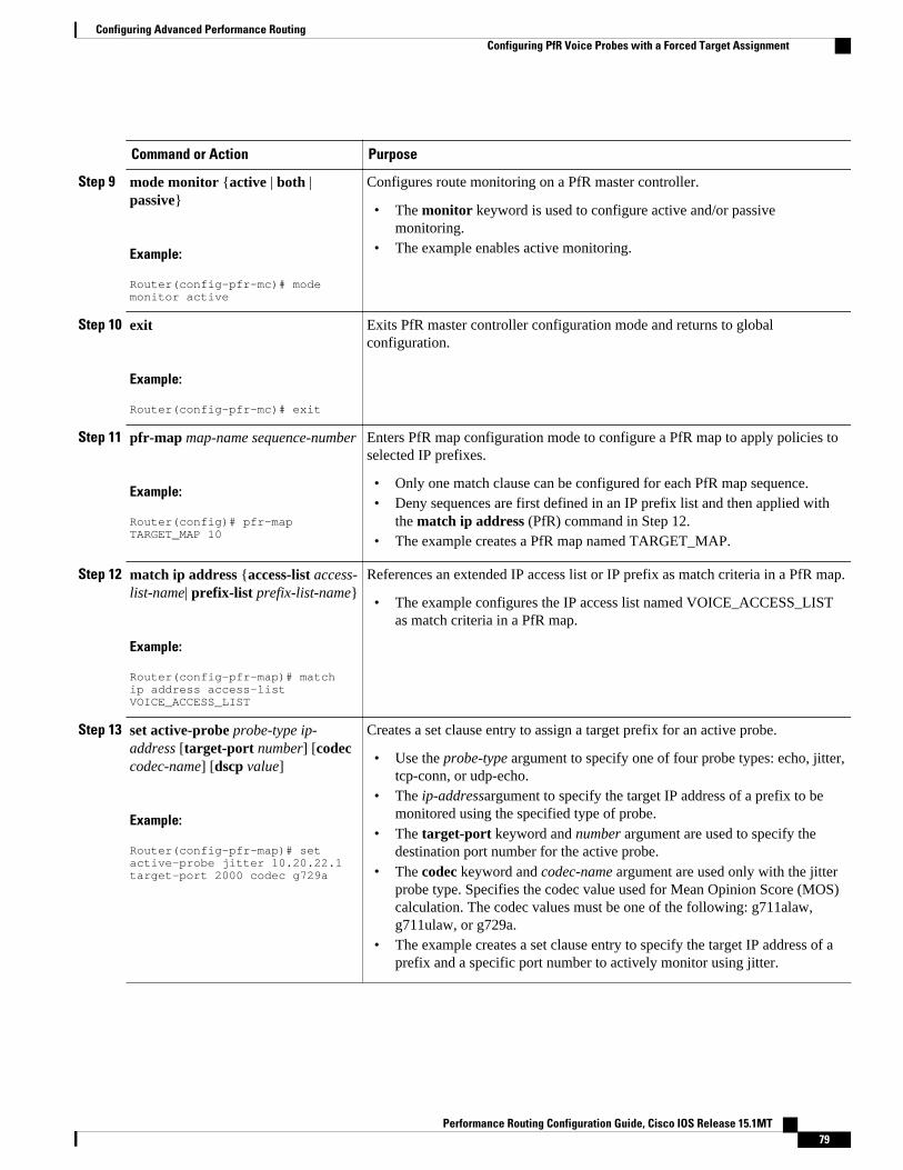
Command or Action Purpose
Step 9 mode monitor {active | both |passive}
Example:
Router(config-pfr-mc)# mode monitor active
Configures route monitoring on a PfR master controller.
• The monitor keyword is used to configure active and/or passivemonitoring.
• The example enables active monitoring.
Step 10 exit
Example:
Router(config-pfr-mc)# exit
Exits PfR master controller configuration mode and returns to globalconfiguration.
Step 11 pfr-map map-name sequence-number
Example:
Router(config)# pfr-map TARGET_MAP 10
Enters PfR map configuration mode to configure a PfR map to apply policies toselected IP prefixes.
• Only one match clause can be configured for each PfR map sequence.• Deny sequences are first defined in an IP prefix list and then applied with
the match ip address (PfR) command in Step 12.• The example creates a PfR map named TARGET_MAP.
Step 12 match ip address {access-list access-list-name| prefix-list prefix-list-name}
Example:
Router(config-pfr-map)# match ip address access-list VOICE_ACCESS_LIST
References an extended IP access list or IP prefix as match criteria in a PfR map.
• The example configures the IP access list named VOICE_ACCESS_LISTas match criteria in a PfR map.
Step 13 set active-probe probe-type ip-address [target-port number] [codeccodec-name] [dscp value]
Example:
Router(config-pfr-map)# set active-probe jitter 10.20.22.1 target-port 2000 codec g729a
Creates a set clause entry to assign a target prefix for an active probe.
• Use the probe-type argument to specify one of four probe types: echo, jitter,tcp-conn, or udp-echo.
• The ip-addressargument to specify the target IP address of a prefix to bemonitored using the specified type of probe.
• The target-port keyword and number argument are used to specify thedestination port number for the active probe.
• The codec keyword and codec-name argument are used only with the jitterprobe type. Specifies the codec value used for Mean Opinion Score (MOS)calculation. The codec values must be one of the following: g711alaw,g711ulaw, or g729a.
• The example creates a set clause entry to specify the target IP address of aprefix and a specific port number to actively monitor using jitter.
Configuring Advanced Performance RoutingConfiguring PfR Voice Probes with a Forced Target Assignment
Performance Routing Configuration Guide, Cisco IOS Release 15.1MT 79

Command or Action Purpose
Step 14 set probe frequency seconds
Example:
Router(config-pfr-map)# set probe frequency 10
Creates a set clause entry to set the frequency of the PfR active probe.
• The seconds argument is used to set the time, in seconds, between the activeprobe monitoring of the specified IP prefixes.
• The example creates a set clause to set the active probe frequency to 10seconds.
Step 15 set jitter threshold maximum
Example:
Router(config-pfr-map)# set jitter threshold 20
Creates a set clause entry to configure the jitter threshold value.
• The threshold keyword is used to configure the maximum jitter value, inmilliseconds.
• The example creates a set clause that sets the jitter threshold value to 20 fortraffic that is matched in the same PfR map sequence.
Step 16 set mos {threshold minimum percentpercent}
Example:
Router(config-pfr-map)# set mos threshold 4.0 percent 30
Creates a set clause entry to configure the MOS threshold and percentage valuesused to decide whether an alternate exit is be selected.
• The threshold keyword is used to configure the minimum MOS value.• The percent keyword is used to configure the percentage of MOS values
that are below the MOS threshold.• PfR calculates the percentage of MOS values below the MOS threshold that
are recorded in a five-minute period. If the percentage value exceeds theconfigured percent value or the default value, the master controller searchesfor alternate exit links.
• The example creates a set clause that sets the threshold MOS value to 4.0and the percent value to 30 percent for traffic that is matched in the samePfR map sequence.
Step 17 set delay {relative percentage |threshold maximum}
Example:
Router(config-pfr-map)# set delay threshold 100
Creates a set clause entry to configure the delay threshold.
• The delay threshold can be configured as a relative percentage or as anabsolute value for match criteria.
• The relative keyword is used to configure a relative delay percentage. Therelative delay percentage is based on a comparison of short-term and long-term measurements.
• The threshold keyword is used to configure the absolute maximum delayperiod in milliseconds.
• The example creates a set clause that sets the absolute maximum delaythreshold to 100 milliseconds for traffic that is matched in the same PfRmap sequence.
Step 18 end
Example:
Router(config-pfr-map)# end
Exits PfR map configuration mode and enters privileged EXEC mode.
Configuring Advanced Performance Routing Configuring PfR Voice Probes with a Forced Target Assignment
Performance Routing Configuration Guide, Cisco IOS Release 15.1MT80

Command or Action Purpose
Step 19 show pfr master active-probes[appl| forced]
Example:
Router# show pfr master active-probes forced
Displays connection and status information about active probes on a PfR mastercontroller.
• The output from this command displays the active probe type anddestination, the border router that is the source of the active probe, the targetprefixes that are used for active probing, and whether the probe was learnedor configured.
• The appl keyword is used to filter the output to display information aboutapplications optimized by the master controller.
• The forced keyword is used to show any forced targets that are assigned.• The example displays connection and status information about the active
probes generated for voice traffic configured with a forced targetassignment.
Examples
This example shows output from the show pfr master active-probes forced command. The output isfiltered to display only connection and status information about the active probes generated for voice trafficconfigured with a forced target assignment.
Router# show pfr master active-probes forcedOER Master Controller active-probesBorder = Border Router running this ProbePolicy = Forced target is configure under this policyType = Probe TypeTarget = Target AddressTPort = Target PortN - Not applicableThe following Forced Probes are running:Border State Policy Type Target TPort10.20.20.2 ACTIVE 40 jitter 10.20.22.1 3050 10.20.21.3 ACTIVE 40 jitter 10.20.22.4 3050
Configuring PfR Voice Probes for Fast FailoverPerform this task to enable fast monitoring using PfR jitter probes. In fast failover monitoring mode, allexits are continuously probed using active monitoring and passive monitoring. The probe frequency can beset to a lower frequency in fast failover monitoring mode than for other monitoring modes, to allow a fasterfailover capability. Fast failover monitoring can be used with all types of active probes: ICMP echo, jitter,TCP connection, and UDP echo.
Fast failover monitoring is designed for traffic classes that are very sensitive to performance issues orcongested links, and voice traffic is very sensitive to any dropped links. In this example, the fast failovermonitoring mode is enabled and the voice traffic to be monitored is identified using an IP prefix list. Toreduce some of the overhead that fast failover monitoring produces, the active voice probes are assigned aforced target for PfR. The PfR probe frequency is set to 2 seconds. In the examples section after the tasktable, the show pfr master prefix command is used to show the policy configuration for the prefixspecified in the task steps and some logging output is displayed to show that fast failover is configured.
Configuring Advanced Performance RoutingConfiguring PfR Voice Probes for Fast Failover
Performance Routing Configuration Guide, Cisco IOS Release 15.1MT 81

Note In fast monitoring mode, probe targets are learned as well as learned prefixes. To avoid triggering largenumbers of probes in the network, use fast monitoring mode only for real time applications and criticalapplications with performance sensitive traffic.
Before configuring the PfR jitter probe on the source device, the IP SLAs Responder must be enabled onthe target device (the operational target). The IP SLAs Responder is available only on Cisco IOS software-based devices. Start this task at the network device that runs the IP SLAs Responder.
Note The device that runs the IP SLAs Responder does not have to be configured for PfR.
SUMMARY STEPS
1. enable
2. configure terminal
3. ip sla monitor responder
4. exit
5. Move to the network device that is the PfR master controller.
6. enable
7. configure terminal
8. ip prefix-list list-name [seq seq-value]{deny network/length | permit network/length}[le le-value]
9. Repeat Step 4 for more prefix list entries, as required.
10. pfr-map map-name sequence-number
11. match traffic-class prefix-list prefix-list-name
12. set mode monitor {active | both| fast| passive}
13. set jitter threshold maximum
14. set mos {threshold minimum percent percent}
15. set delay {relative percentage | threshold maximum}
16. set active-probe probe-type ip-address [target-port number] [codec codec-name] [dscp value]
17. set probe frequency seconds
18. end
19. show pfr master prefix [prefix[detail| policy| traceroute[exit-id| border-address| current]]]
DETAILED STEPS
Command or Action Purpose
Step 1 enable
Example:
Router> enable
Enables privileged EXEC mode.
• Enter your password if prompted.
Configuring Advanced Performance Routing Configuring PfR Voice Probes for Fast Failover
Performance Routing Configuration Guide, Cisco IOS Release 15.1MT82

Command or Action Purpose
Step 2 configure terminal
Example:
Router# configure terminal
Enters global configuration mode.
Step 3 ip sla monitor responder
Example:
Router(config)# ip sla monitor responder
Enables the IP SLAs Responder.
Step 4 exit
Example:
Router(config)# exit
Exits global configuration mode and returns to privileged EXEC mode.
Step 5 Move to the network device that is thePfR master controller.
--
Step 6 enable
Example:
Router> enable
Enables privileged EXEC mode.
• Enter your password if prompted.
Step 7 configure terminal
Example:
Router# configure terminal
Enters global configuration mode.
Step 8 ip prefix-list list-name [seq seq-value]{deny network/length | permit network/length}[le le-value]
Example:
Router(config)# ip prefix-list VOICE_FAIL_LIST permit 10.1.0.0/24
Creates an IP prefix list.
• The IP prefix list specified here is used in a PfR map to specify thedestination IP addresses for a traffic class.
• The example creates an IP prefix list named VOICE_FAIL_LIST for PfRto profile the prefix, 10.1.0.0/24.
Step 9 Repeat Step 4 for more prefix listentries, as required.
--
Configuring Advanced Performance RoutingConfiguring PfR Voice Probes for Fast Failover
Performance Routing Configuration Guide, Cisco IOS Release 15.1MT 83

Command or Action Purpose
Step 10 pfr-map map-name sequence-number
Example:
Router(config)# pfr-map FAST_FAIL_MAP 10
Enters PfR map configuration mode to configure a PfR map to apply policies toselected IP prefixes.
• Only one match clause can be configured for each PfR map sequence.• The example creates a PfR map named FAST_FAIL_MAP.
Step 11 match traffic-class prefix-list prefix-list-name
Example:
Router(config-pfr-map)# match traffic-class prefix-list VOICE_FAIL_LIST
References an IP prefix list as traffic class match criteria in a PfR map.
• The example configures the IP prefix list named VOICE_FAIL_LIST asmatch criteria in a PfR map.
Step 12 set mode monitor {active | both| fast|passive}
Example:
Router(config-pfr-map)# set mode monitor fast
Creates a set clause entry to configure route monitoring on a PfR mastercontroller.
• The monitor keyword is used to configure active and/or passivemonitoring.
• The fast keyword is used to configure fast failover monitoring modewhere continuous active monitoring is enabled as well as passivemonitoring.
• The example enables fast failover monitoring.
Step 13 set jitter threshold maximum
Example:
Router(config-pfr-map)# set jitter threshold 12
Creates a set clause entry to configure the jitter threshold value.
• The threshold keyword is used to configure the maximum jitter value, inmilliseconds.
• The example creates a set clause that sets the jitter threshold value to 12for traffic that is matched in the same PfR map sequence.
Step 14 set mos {threshold minimum percentpercent}
Example:
Router(config-pfr-map)# set mos threshold 3.6 percent 30
Creates a set clause entry to configure the MOS threshold and percentagevalues used to decide whether an alternate exit is be selected.
• The threshold keyword is used to configure the minimum MOS value.• The percent keyword is used to configure the percentage of MOS values
that are below the MOS threshold.• PfR calculates the percentage of MOS values below the MOS threshold
that are recorded in a five-minute period. If the percentage value exceedsthe configured percent value or the default value, the master controllersearches for alternate exit links.
• The example creates a set clause that sets the threshold MOS value to 3.6and the percent value to 30 percent for traffic that is matched in the samePfR map sequence.
Configuring Advanced Performance Routing Configuring PfR Voice Probes for Fast Failover
Performance Routing Configuration Guide, Cisco IOS Release 15.1MT84

Command or Action Purpose
Step 15 set delay {relative percentage |threshold maximum}
Example:
Router(config-pfr-map)# set delay relative 50
Creates a set clause entry to configure the delay threshold.
• The delay threshold can be configured as a relative percentage or as anabsolute value for match criteria.
• The relative keyword is used to configure a relative delay percentage. Therelative delay percentage is based on a comparison of short-term and long-term measurements.
• The threshold keyword is used to configure the absolute maximum delayperiod in milliseconds.
• The example creates a set clause that sets the relative delay percentage to50 percent for traffic that is matched in the same PfR map sequence.
Step 16 set active-probe probe-type ip-address[target-port number] [codec codec-name] [dscp value]
Example:
Router(config-pfr-map)# set active-probe jitter 10.120.120.1 target-port 20 codec g729a
Creates a set clause entry to assign a target prefix for an active probe.
• Use the probe-type argument to specify one four probe types: echo, jitter,tcp-conn, or udp-echo.
• The ip-addressargument to specify the target IP address of a prefix to bemonitored using the specified type of probe.
• The target-port keyword and number argument are used to specify thedestination port number for the active probe.
• The codec keyword and codec-name argument are used only with the jitterprobe type. Specifies the codec value used for Mean Opinion Score (MOS)calculation. The codec values must be one of the following: g711alaw,g711ulaw, or g729a.
• The example creates a set clause entry to specify the target IP address of aprefix and a specific port number to actively monitor using jitter.
Step 17 set probe frequency seconds
Example:
Router(config-pfr-map)# set probe frequency 2
Creates a set clause entry to set the frequency of the PfR active probe.
• The seconds argument is used to set the time, in seconds, between theactive probe monitoring of the specified IP prefixes.
• The example creates a set clause to set the active probe frequency to 2seconds.
Note A probe frequency of less than 4 seconds is possible here because thefast failover monitoring mode has been enabled in Step 12.
Step 18 end
Example:
Router(config-pfr-map)# end
Exits PfR map configuration mode and enters privileged EXEC mode.
Configuring Advanced Performance RoutingConfiguring PfR Voice Probes for Fast Failover
Performance Routing Configuration Guide, Cisco IOS Release 15.1MT 85

Command or Action Purpose
Step 19 show pfr master prefix [prefix[detail|policy| traceroute[exit-id| border-address| current]]]
Example:
Router# show pfr master prefix 10.1.1.0/24 policy
(Optional) Displays the status of monitored prefixes.
• The prefixargument is entered as an IP address and bit length mask.• The policykeyword is used to display policy information for the specified
prefix.• The example displays policy information for the prefix, 10.1.1.0/24.
Examples
This example shows output from the show pfr master prefixcommand when a prefix is specified with thepolicy keyword to display the policy configured for the prefix 10.1.1.0/24. Note that the mode monitor isset to fast, which automatically sets the select-exit to best, and allows the probe frequency to be set at 2.
Router# show pfr master prefix 10.1.1.0/24 policy* Overrides Default Policy Settingpfr-map MAP 10 sequence no. 8444249301975040, provider id 1, provider priority 30 host priority 0, policy priority 10, Session id 0 match ip prefix-lists: VOICE_FAIL_LIST backoff 90 90 90 delay relative 50 holddown 90 periodic 0 *probe frequency 2 mode route control *mode monitor fast *mode select-exit best loss relative 10 *jitter threshold 12 mos threshold 3.60 percent 30 unreachable relative 50 next-hop not set forwarding interface not set resolve jitter priority 1 variance 10 resolve utilization priority 12 variance 20 Forced Assigned Target List: active-probe jitter 10.120.120.1 target-port 20 codec g729a
Configuring the Source Address of an Active ProbePerform this task on a border router to specify the source interface for active probing. The active probesource interface is configured on the border router with the active-probe address source ((PfR) in PfRborder router configuration mode. The active probe source interface IP address must be unique to ensurethat the probe reply is routed back to the specified source interface.
The following is default behavior:
• The source IP address is used from the default PfR external interface that transmits the active probewhen this command is not enabled or if the no form is entered.
• If the interface is not configured with an IP address, the active probe will not be generated.• If the IP address is changed after the interface has been configured as an active probe source, active
probing is stopped, and then restarted with the new IP address.• If the IP address is removed after the interface has been configured as an active probe source, active
probing is stopped and not restarted until a valid primary IP address is configured.
Configuring Advanced Performance Routing Configuring the Source Address of an Active Probe
Performance Routing Configuration Guide, Cisco IOS Release 15.1MT86

SUMMARY STEPS
1. enable
2. configure terminal
3. pfr border
4. active-probe address source interface type number
5. end
6. show pfr border active-probes
DETAILED STEPS
Command or Action Purpose
Step 1 enable
Example:
Router> enable
Enables privileged EXEC mode.
• Enter your password if prompted.
Step 2 configure terminal
Example:
Router# configure terminal
Enters global configuration mode.
Step 3 pfr border
Example:
Router(config)# pfr border
Enters PfR border router configuration mode to configure arouter as a border router.
Step 4 active-probe address source interface type number
Example:
Router(config-pfr-br)# active-probe address source interface FastEthernet 0/0
Configures an interface on a border router as the active-probesource.
• The example configures interface FastEthernet 0/0 as thesource interface.
Step 5 end
Example:
Router(config-pfr-br)# end
Exits PfR border router configuration mode and entersprivileged EXEC mode.
Configuring Advanced Performance RoutingConfiguring the Source Address of an Active Probe
Performance Routing Configuration Guide, Cisco IOS Release 15.1MT 87
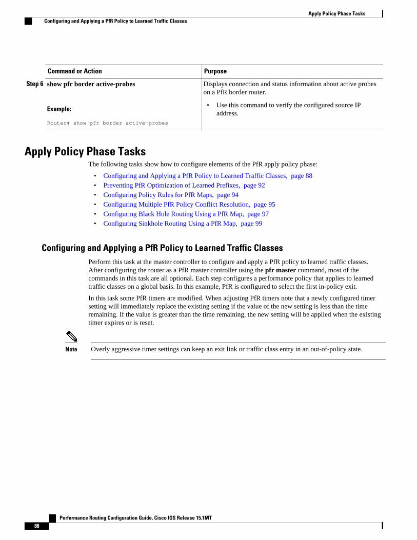
Command or Action Purpose
Step 6 show pfr border active-probes
Example:
Router# show pfr border active-probes
Displays connection and status information about active probeson a PfR border router.
• Use this command to verify the configured source IPaddress.
Apply Policy Phase TasksThe following tasks show how to configure elements of the PfR apply policy phase:
• Configuring and Applying a PfR Policy to Learned Traffic Classes, page 88
• Preventing PfR Optimization of Learned Prefixes, page 92
• Configuring Policy Rules for PfR Maps, page 94
• Configuring Multiple PfR Policy Conflict Resolution, page 95
• Configuring Black Hole Routing Using a PfR Map, page 97
• Configuring Sinkhole Routing Using a PfR Map, page 99
Configuring and Applying a PfR Policy to Learned Traffic ClassesPerform this task at the master controller to configure and apply a PfR policy to learned traffic classes.After configuring the router as a PfR master controller using the pfr master command, most of thecommands in this task are all optional. Each step configures a performance policy that applies to learnedtraffic classes on a global basis. In this example, PfR is configured to select the first in-policy exit.
In this task some PfR timers are modified. When adjusting PfR timers note that a newly configured timersetting will immediately replace the existing setting if the value of the new setting is less than the timeremaining. If the value is greater than the time remaining, the new setting will be applied when the existingtimer expires or is reset.
Note Overly aggressive timer settings can keep an exit link or traffic class entry in an out-of-policy state.
Apply Policy Phase Tasks Configuring and Applying a PfR Policy to Learned Traffic Classes
Performance Routing Configuration Guide, Cisco IOS Release 15.1MT88
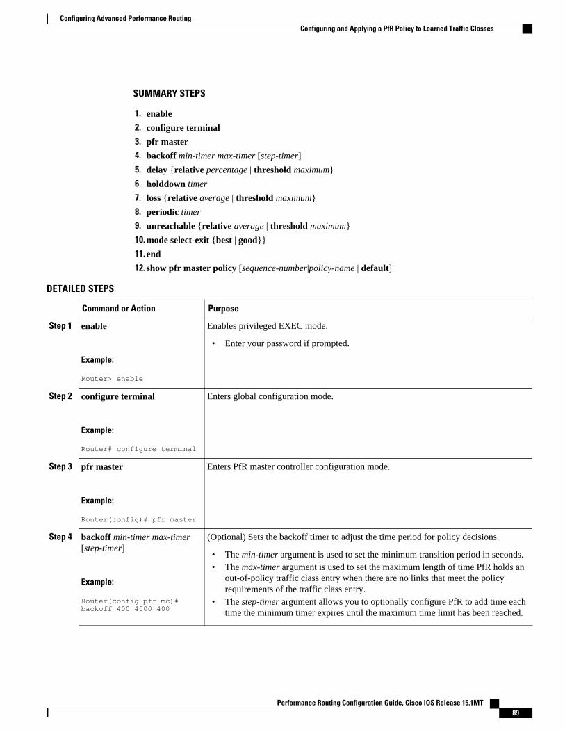
SUMMARY STEPS
1. enable
2. configure terminal
3. pfr master
4. backoff min-timer max-timer [step-timer]
5. delay {relative percentage | threshold maximum}
6. holddown timer
7. loss {relative average | threshold maximum}
8. periodic timer
9. unreachable {relative average | threshold maximum}
10. mode select-exit {best | good}}
11. end
12. show pfr master policy [sequence-number|policy-name | default]
DETAILED STEPS
Command or Action Purpose
Step 1 enable
Example:
Router> enable
Enables privileged EXEC mode.
• Enter your password if prompted.
Step 2 configure terminal
Example:
Router# configure terminal
Enters global configuration mode.
Step 3 pfr master
Example:
Router(config)# pfr master
Enters PfR master controller configuration mode.
Step 4 backoff min-timer max-timer[step-timer]
Example:
Router(config-pfr-mc)# backoff 400 4000 400
(Optional) Sets the backoff timer to adjust the time period for policy decisions.
• The min-timer argument is used to set the minimum transition period in seconds.• The max-timer argument is used to set the maximum length of time PfR holds an
out-of-policy traffic class entry when there are no links that meet the policyrequirements of the traffic class entry.
• The step-timer argument allows you to optionally configure PfR to add time eachtime the minimum timer expires until the maximum time limit has been reached.
Configuring Advanced Performance RoutingConfiguring and Applying a PfR Policy to Learned Traffic Classes
Performance Routing Configuration Guide, Cisco IOS Release 15.1MT 89

Command or Action Purpose
Step 5 delay {relative percentage |threshold maximum}
Example:
Router(config-pfr-mc)# delay relative 80
(Optional) Sets the delay threshold as a relative percentage or as an absolute value.
• The relative keyword is used to configure a relative delay percentage. Therelative delay percentage is based on a comparison of short-term and long-termmeasurements.
• The thresholdkeyword is used to configure the absolute maximum delay periodin milliseconds.
• If the configured delay threshold is exceeded, then the prefix is out-of-policy.• The example sets a delay threshold of 80 percent based on a relative average.
Step 6 holddown timer
Example:
Router(config-pfr-mc)# holddown 600
(Optional) Configures the traffic class entry route dampening timer to set the minimumperiod of time that a new exit must be used before an alternate exit can be selected.
• PfR does not implement route changes while a traffic class entry is in theholddown state.
• When the holddown timer expires, PfR will select the best exit based onperformance and policy configuration.
• PfR starts the process of finding an alternate path if the current exit for a trafficclass entry becomes unreachable.
• The example sets the traffic class entry route dampening timer to 600 seconds.
Step 7 loss {relative average |threshold maximum}
Example:
Router(config-pfr-mc)# loss relative 20
(Optional) Sets the relative or maximum packet loss limit that PfR will permit for atraffic class entry.
• The relative keyword sets a relative percentage of packet loss based on acomparison of short-term and long-term packet loss percentages.
• The threshold keyword sets the absolute packet loss based on packets permillion.
• The example configures the master controller to search for a new exit link whenthe relative percentage of packet loss is equal to or greater than 20 percent.
Step 8 periodic timer
Example:
Router(config-pfr-mc)# periodic 300
(Optional) Configures PfR to periodically select the best exit link when the periodictimer expires.
• When this command is enabled, the master controller will periodically evaluateand then make policy decisions for traffic classes.
• The example sets the periodic timer to 300 seconds. When the timer expires, PfRwill select either the best exit or the first in-policy exit.
Note The mode select-exit command is used to determine if PfR selects the first in-policy exit or the best available exit when this timer expires.
Configuring Advanced Performance Routing Configuring and Applying a PfR Policy to Learned Traffic Classes
Performance Routing Configuration Guide, Cisco IOS Release 15.1MT90

Command or Action Purpose
Step 9 unreachable {relative average| threshold maximum}
Example:
Router(config-pfr-mc)# unreachable relative 10
(Optional) Sets the maximum number of unreachable hosts.
• This command is used to specify the relative percentage or the absolute maximumnumber of unreachable hosts, based on flows per million (fpm), that PfR willpermit for a traffic class entry. If the absolute number or relative percentage ofunreachable hosts is greater than the user-defined or the default value, PfRdetermines that the traffic class entry is OOP and searches for an alternate exitlink.
• The relative keyword is used to configure the relative percentage of unreachablehosts. The relative unreachable host percentage is based on a comparison of short-term and long-term measurements.
• The threshold keyword is used to configure the absolute maximum number ofunreachable hosts based on fpm.
• The example configures PfR to search for a new exit link for a traffic class entrywhen the relative percentage of unreachable hosts is equal to or greater than 10percent.
Step 10 mode select-exit {best | good}}
Example:
Router(config-pfr-mc)# mode select-exit good
Enables the exit link selection based on performance or policy.
• The select-exit keyword is used to configure the master controller to select eitherthe best available exit when the bestkeyword is entered or the first in-policy exitwhen the good keyword is entered.
Step 11 end
Example:
Router(config-pfr-mc)# end
Exits PfR master controller configuration mode and enters privileged EXEC mode.
Step 12 show pfr master policy[sequence-number|policy-name |default]
Example:
Router# show pfr master policy
Displays policy settings on a PfR master controller.
• The output of this command displays default policies and, optionally, policiesconfigured with a PfR map.
• The sequence-number argument is used to display policy settings for the specifiedPfR map sequence.
• The policy-name argument is used to display policy settings for the specified PfRpolicy map name.
• Thedefaultkeyword is used to display only the default policy settings.• The example displays the default policy settings and policy settings updated by
the configuration in this task.
Examples
This example shows output from the show pfr master policy command. Default policy settings aredisplayed except where the configuration in this task has overwritten specific policy settings.
Router# show pfr master policyDefault Policy Settings:
Configuring Advanced Performance RoutingConfiguring and Applying a PfR Policy to Learned Traffic Classes
Performance Routing Configuration Guide, Cisco IOS Release 15.1MT 91

backoff 400 4000 400 delay relative 80 holddown 600 periodic 300 probe frequency 56 mode route observe mode monitor both mode select-exit good loss relative 20 unreachable relative 10 resolve delay priority 11 variance 20 resolve utilization priority 12 variance 20 *tag 0
Preventing PfR Optimization of Learned PrefixesPerform this task at the master controller to configure and apply a PfR policy to prevent PfR fromattempting to optimize specified learned prefixes. This task is useful when you know a few prefixes thatyou want to exclude from the PfR optimization, but these prefixes will be learned automatically by PfR. Inthis task, an IP prefix list is configured with two entries for different prefixes that are not to be optimized.A PfR map is configured with two entries in a sequence that will prevent PfR from optimizing the prefixesspecified in the prefix list, although the prefixes may be learned. If the sequence numbers of the PfR mapentries are reversed, PfR will learn and attempt to optimize the prefixes.
SUMMARY STEPS
1. enable
2. configure terminal
3. ip prefix-list list-name [seq seq-value] {deny network / length| permit network / length}
4. ip prefix-list list-name [seq seq-value] {deny network / length| permit network / length}
5. pfr-map map-name sequence-number
6. match ip address {access-list access-list-name| prefix-list prefix-list-name}
7. exit
8. pfr-map map-name sequence-number
9. match pfr learn {delay| inside| throughput}
10. end
DETAILED STEPS
Command or Action Purpose
Step 1 enable
Example:
Router> enable
Enables privileged EXEC mode.
• Enter your password if prompted.
Step 2 configure terminal
Example:
Router# configure terminal
Enters global configuration mode.
Configuring Advanced Performance Routing Preventing PfR Optimization of Learned Prefixes
Performance Routing Configuration Guide, Cisco IOS Release 15.1MT92

Command or Action Purpose
Step 3 ip prefix-list list-name [seq seq-value]{deny network / length| permit network /length}
Example:
Router(config)# ip prefix-list DENY_LIST deny 10.1.1.0/24
Creates an IP prefix list.
• IP prefix lists are used to manually deny or permit prefixes formonitoring by the master controller.
• The prefixes specified in the IP prefix list are imported into the PfR mapwith the match ip address (PfR) command.
• The example creates an IP prefix list with an entry that denies prefixesonly from the 10.1.1.0/24 subnet.
Step 4 ip prefix-list list-name [seq seq-value]{deny network / length| permit network /length}
Example:
Router(config)# ip prefix-list DENY_LIST deny 172.20.1.0/24
Creates an IP prefix list.
• IP prefix lists are used to manually deny or permit prefixes formonitoring by the master controller.
• The prefixes specified in the IP prefix list are imported into the PfR mapwith the match ip address (PfR) command.
• The example creates an IP prefix entry that denies prefixes only fromthe 172.20.1.0/24 subnet.
Step 5 pfr-map map-name sequence-number
Example:
Router(config)# pfr-map DENY_MAP 10
Enters PfR map configuration mode to configure a PfR map to apply policiesto selected IP prefixes.
• Only one match clause can be configured for each PfR map sequence.• Deny sequences are first defined in an IP prefix list and then applied
with the match ip address (PfR) command in Step 6.• The example creates a PfR map named DENY_MAP with a sequence
number of 10.
Step 6 match ip address {access-list access-list-name| prefix-list prefix-list-name}
Example:
Router(config-pfr-map)# match ip address prefix-list DENY_LIST
References an extended IP access list or IP prefix list as match criteria in aPfR map.
• The example configures the prefix list named DENY_LIST as matchcriteria in a PfR map.
Step 7 exit
Example:
Router(config-pfr-map)# exit
Exits PfR map configuration mode and returns to global configuration mode.
Step 8 pfr-map map-name sequence-number
Example:
Router(config)# pfr-map DENY_MAP 20
Enters a PfR map entry.
• Only one match clause can be configured for each PfR map sequence.• Deny sequences are first defined in an IP prefix list and then applied
with the match ip address (PfR) command in Step 9.• The example creates a PfR map entry for the PfR map named
DENY_MAP with a sequence number of 20.
Configuring Advanced Performance RoutingPreventing PfR Optimization of Learned Prefixes
Performance Routing Configuration Guide, Cisco IOS Release 15.1MT 93
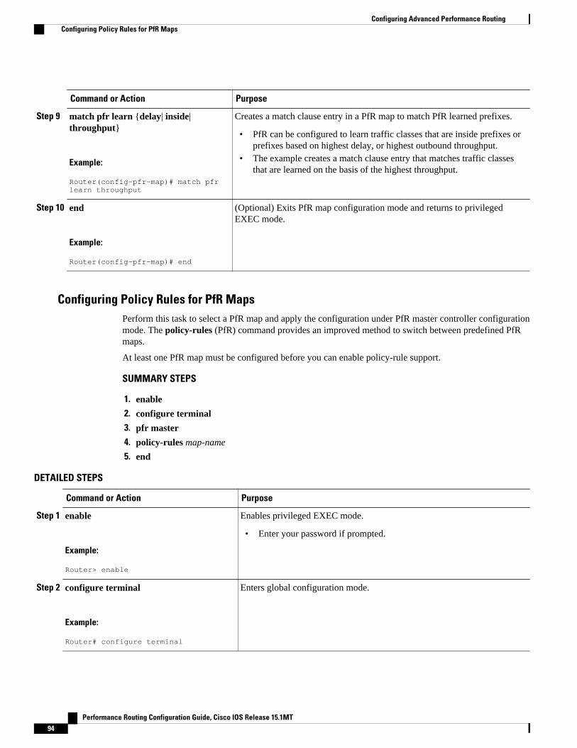
Command or Action Purpose
Step 9 match pfr learn {delay| inside|throughput}
Example:
Router(config-pfr-map)# match pfr learn throughput
Creates a match clause entry in a PfR map to match PfR learned prefixes.
• PfR can be configured to learn traffic classes that are inside prefixes orprefixes based on highest delay, or highest outbound throughput.
• The example creates a match clause entry that matches traffic classesthat are learned on the basis of the highest throughput.
Step 10 end
Example:
Router(config-pfr-map)# end
(Optional) Exits PfR map configuration mode and returns to privilegedEXEC mode.
Configuring Policy Rules for PfR MapsPerform this task to select a PfR map and apply the configuration under PfR master controller configurationmode. The policy-rules (PfR) command provides an improved method to switch between predefined PfRmaps.
At least one PfR map must be configured before you can enable policy-rule support.
SUMMARY STEPS
1. enable
2. configure terminal
3. pfr master
4. policy-rules map-name
5. end
DETAILED STEPS
Command or Action Purpose
Step 1 enable
Example:
Router> enable
Enables privileged EXEC mode.
• Enter your password if prompted.
Step 2 configure terminal
Example:
Router# configure terminal
Enters global configuration mode.
Configuring Advanced Performance Routing Configuring Policy Rules for PfR Maps
Performance Routing Configuration Guide, Cisco IOS Release 15.1MT94

Command or Action Purpose
Step 3 pfr master
Example:
Router(config)# pfr master
Enters PfR master controller configuration mode to configure global prefixand exit link policies.
Step 4 policy-rules map-name
Example:
Router(config-pfr-mc)# policy-rules TARGET_MAP
Applies a configuration from a PfR map to a master controllerconfiguration in PfR master controller configuration mode.
• Reentering this command with a new PfR map name will immediatelyoverwrite the previous configuration. This behavior is designed toallow you to quickly select and switch between predefined PfR maps.
• The example applies the configuration from the PfR map namedTARGET_MAP.
Step 5 end
Example:
Router(config-pfr-mc)# end
Exits PfR master controller configuration mode and enters privilegedEXEC mode.
Configuring Multiple PfR Policy Conflict ResolutionPerform this task to use the PfR resolve function to assign a priority to a PfR policy to avoid any conflictover which policy to run first. Each policy is assigned a unique value, and the policy with the highest valueis selected as the highest priority. By default, a delay policy has the highest priority and a traffic load(utilization) policy has the second highest priority. Assigning a priority value to any policy will overridedefault settings.
SUMMARY STEPS
1. enable
2. configure terminal
3. pfr master
4. resolve {cost priority value| delay priority value variance percentage | loss priority value variancepercentage | range priority value | utilization priority value variance percentage}
5. Repeat Step 4 to assign a priority for each required PfR policy.
6. end
Configuring Advanced Performance RoutingConfiguring Multiple PfR Policy Conflict Resolution
Performance Routing Configuration Guide, Cisco IOS Release 15.1MT 95

DETAILED STEPS
Command or Action Purpose
Step 1 enable
Example:
Router> enable
Enables privileged EXEC mode.
• Enter your password if prompted.
Step 2 configure terminal
Example:
Router# configure terminal
Enters global configuration mode.
Step 3 pfr master
Example:
Router(config)# pfr master
Enters PfR master controller configuration mode.
Step 4 resolve {cost priority value| delay priorityvalue variance percentage | loss priority valuevariance percentage | range priority value |utilization priority value variance percentage}
Example:
Router(config-pfr-mc)# resolve loss priority 2 variance 10
Sets policy priority or resolves policy conflicts.
• This command is used to set priority when multiple policies areconfigured for the same prefix. When this command is configured,the policy with the highest priority will be selected to determinethe policy decision.
• The priority keyword is used to specify the priority value. Settingthe number 1 assigns the highest priority to a policy. Setting thenumber 10 assigns the lowest priority.
• Each policy must be assigned a different priority number.• The variance keyword is used to set an allowable variance for a
user-defined policy. This keyword configures the allowablepercentage that an exit link or prefix can vary from the user-defined policy value and still be considered equivalent.
• The example sets the priority for loss policies to 2 with a 10percent variance.
Note Variance cannot be configured for range or cost policies.
Step 5 Repeat Step 4 to assign a priority for eachrequired PfR policy.
--
Step 6 end
Example:
Router(config-pfr-mc)# end
Exits PfR master controller configuration mode, and enters privilegedEXEC mode.
Configuring Advanced Performance Routing Configuring Multiple PfR Policy Conflict Resolution
Performance Routing Configuration Guide, Cisco IOS Release 15.1MT96

Configuring Black Hole Routing Using a PfR MapPerform this task to configure a PfR map to filter packets to be forwarded to a null interface, meaning thatthe packets are discarded in a “black hole.” The prefix list is configured after an IP prefix is identified asthe source of the attack on the network. Some protocols such as BGP allow the redistribution of black holeroutes, but other protocols do not.
This optional task can help prevent and mitigate attacks on your network
SUMMARY STEPS
1. enable
2. configure terminal
3. ip prefix-list list-name [seq seq-value] {deny network / length| permit network / length}
4. pfr-map map-name sequence-number
5. match ip address {access-list access-list-name | prefix-list prefix-list-name}
6. set interface null0
7. end
DETAILED STEPS
Command or Action Purpose
Step 1 enable
Example:
Router> enable
Enables privileged EXEC mode.
• Enter your password if prompted.
Step 2 configure terminal
Example:
Router# configure terminal
Enters global configuration mode.
Configuring Advanced Performance RoutingConfiguring Black Hole Routing Using a PfR Map
Performance Routing Configuration Guide, Cisco IOS Release 15.1MT 97

Command or Action Purpose
Step 3 ip prefix-list list-name [seq seq-value]{deny network / length| permitnetwork / length}
Example:
Router(config)# ip prefix-list BLACK_HOLE_LIST seq 10 permit 10.20.21.0/24
Creates an IP prefix list.
• IP prefix lists are used to manually select prefixes for monitoring by the PfRmaster controller.
• A master controller can monitor and control an exact prefix of any lengthincluding the default route. If an exact prefix is specified, PfR monitors onlythe exact prefix.
• A master controller can monitor and control an inclusive prefix using thelekeyword set to 32. PfR monitors the configured prefix and any more specificprefixes (for example, configuring the 10.0.0.0/8 le 32 prefix would includethe 10.1.0.0/16 and the 10.1.1.0/24 prefixes) over the same exit and recordsthe information in the routing information base (RIB).
• The prefixes specified in the IP prefix list are imported into a PfR map usingthe match ip address (PfR) command.
• The example creates an IP prefix list named BLACK_HOLE_LIST thatpermits prefixes from the 10.20.21.0/24 subnet.
Step 4 pfr-map map-name sequence-number
Example:
Router(config)# pfr-map BLACK_HOLE_MAP 10
Enters PfR map configuration mode to configure a PfR map to apply policies toselected IP prefixes.
• Only one match clause can be configured for each PfR map sequence.• Deny sequences are first defined in an IP prefix list and then applied with
the match ip address (PfR) command in the previous step.• The example creates a PfR map named BLACK_HOLE_MAP.
Step 5 match ip address {access-list access-list-name | prefix-list prefix-list-name}
Example:
Router(config-pfr-map)# match ip address prefix-list BLACK_HOLE_LIST
References an extended IP access list or IP prefix as match criteria in a PfR map.
• The example configures the IP prefix list named BLACK_HOLE_LIST asmatch criteria in a PfR map.
Step 6 set interface null0
Example:
Router(config-pfr-map)# set interface null0
Creates a set clause entry to forward packets to the null interface, meaning thatthey are discarded.
• The example creates a set clause entry to specify that the packets matchingthe prefix list, BLACK_HOLE_LIST, are discarded.
Step 7 end
Example:
Router(config-pfr-map)# end
(Optional) Exits PfR map configuration mode and returns to privileged EXECmode.
Configuring Advanced Performance Routing Configuring Black Hole Routing Using a PfR Map
Performance Routing Configuration Guide, Cisco IOS Release 15.1MT98

Configuring Sinkhole Routing Using a PfR MapPerform this task to configure a PfR map to filter packets to be forwarded to a next hop. The next hop is arouter where the packets can be stored, analyzed, or discarded (the sinkhole analogy). The prefix list isconfigured after an IP prefix is identified as the source of an attack on the network.
This optional task can help prevent and mitigate attacks on your network
SUMMARY STEPS
1. enable
2. configure terminal
3. ip prefix-list list-name [seq seq-value] {deny network / length| permit network / length}
4. pfr-map map-name sequence-number
5. match ip address {access-list access-list-name| prefix-list prefix-list-name}
6. set next-hop ip-address
7. end
DETAILED STEPS
Command or Action Purpose
Step 1 enable
Example:
Router> enable
Enables privileged EXEC mode.
• Enter your password if prompted.
Step 2 configure terminal
Example:
Router# configure terminal
Enters global configuration mode.
Configuring Advanced Performance RoutingConfiguring Sinkhole Routing Using a PfR Map
Performance Routing Configuration Guide, Cisco IOS Release 15.1MT 99

Command or Action Purpose
Step 3 ip prefix-list list-name [seq seq-value]{deny network / length| permitnetwork / length}
Example:
Router(config)# ip prefix-list SINKHOLE_LIST seq 10 permit 10.20.21.0/24
Creates an IP prefix list.
• IP prefix lists are used to manually select prefixes for monitoring by thePfR master controller.
• A master controller can monitor and control an exact prefix of any lengthincluding the default route. If an exact prefix is specified, PfR monitorsonly the exact prefix.
• A master controller can monitor and control an inclusive prefix using thelekeyword set to 32. PfR monitors the configured prefix and any morespecific prefixes (for example, configuring the 10.0.0.0/8 le 32 prefixwould include the 10.1.0.0/16 and the 10.1.1.0/24 prefixes) over the sameexit and records the information in the routing information base (RIB).
• The prefixes specified in the IP prefix list are imported into a PfR mapusing the match ip address (PfR) command.
• The example creates an IP prefix list named SINKHOLE_LIST thatpermits prefixes from the 10.20.21.0/24 subnet.
Step 4 pfr-map map-name sequence-number
Example:
Router(config-pfr-mc)# pfr-map SINKHOLE_MAP 10
Enters PfR map configuration mode to configure a PfR map to apply policies toselected IP prefixes.
• Only one match clause can be configured for each PfR map sequence.• Deny sequences are first defined in an IP prefix list and then applied with
the match ip address (PfR) command in the previous step.• The example creates a PfR map named SINKHOLE_MAP.
Step 5 match ip address {access-list access-list-name| prefix-list prefix-list-name}
Example:
Router(config-pfr-map)# match ip address prefix-list SINKHOLE_LIST
References an extended IP access list or IP prefix as match criteria in a PfRmap.
• The example configures the IP prefix list named SINKHOLE_LIST asmatch criteria in a PfR map.
Step 6 set next-hop ip-address
Example:
Router(config-pfr-map)# set next-hop 10.20.21.6
Creates a set clause entry specifying that packets are forwarded to the next hop.
• The example creates a set clause entry to specify that the packets matchingthe prefix list, SINKHOLE_LIST, are forwarded to the next hop at10.20.21.6.
Step 7 end
Example:
Router(config)# end
(Optional) Exits PfR map configuration mode and returns to privileged EXECmode.
Configuring Advanced Performance Routing Configuring Sinkhole Routing Using a PfR Map
Performance Routing Configuration Guide, Cisco IOS Release 15.1MT100

Enforce Phase TasksThe following tasks show how to configure elements of the PfR configure and apply policy phase:
• Controlling Application Traffic, page 101
Controlling Application TrafficPerform this task on a master controller to control application traffic. This task shows how to use policy-based routing (PBR) to allow PfR to control specified application traffic classes. Use application-awarepolicy routing to configure application traffic that can be filtered with a permit statement in an extended IPaccess list.
Application traffic such as Telnet traffic is delay sensitive and long TCP delays can make Telnet sessionsdifficult to use. In this task, an extended IP access list is configured to permit Telnet traffic. A PfR map isconfigured with an extended access list that references a match clause to match Telnet traffic that is sourcedfrom the 192.168.1.0/24 network. PfR route control is enabled and a delay policy is configured to ensurethat Telnet traffic is sent out through exit links with a response time that is equal to, or less than, 30milliseconds. The configuration is verified with the show pfr master appl command.
Note• Border routers must be single-hop peers.• Only named extended IP access lists are supported• Application traffic optimization is supported in PfR only over CEF switching paths
SUMMARY STEPS
1. enable
2. configure terminal
3. ip access-list {standard | extended} access-list-name}
4. [sequence-number] permit protocol source source-wildcard destination destination-wildcard [option option-name][precedence precedence][tos tos] [ttl operator value] [log ][time-range time-range-name][fragments]
5. exit
6. pfr-map map-name sequence-number
7. match ip address {access-list name| prefix-list name}
8. set mode route control
9. set delay {relative percentage | threshold maximum}
10. set resolve {cost priority value | delay priority value variance percentage | loss priority valuevariance percentage | range priority value | utilization priority value variance percentage}
11. end
12. show pfr master appl [access-list name] [detail] | [tcp | udp] [protocol-number] [min-port max-port][dst | src] [detail | policy]
Enforce Phase TasksControlling Application Traffic
Performance Routing Configuration Guide, Cisco IOS Release 15.1MT 101

DETAILED STEPS
Command or Action Purpose
Step 1 enable
Example:
Router> enable
Enables privileged EXEC mode.
• Enter your password if prompted.
Step 2 configure terminal
Example:
Router# configure terminal
Enters global configuration mode.
Step 3 ip access-list {standard | extended} access-list-name}
Example:
Router(config)# ip access-list extended TELNET_ACL
Creates an extended access list and enters extended accesslist configuration mode.
• Only named access lists are supported.
Step 4 [sequence-number] permit protocol source source-wildcard destination destination-wildcard [option option-name][precedence precedence][tos tos] [ttl operator value] [log ][time-range time-range-name][fragments]
Example:
Router(config-ext-nacl)# permit tcp 192.168.1.0 0.0.0.255 any eq telnet
Defines the extended access list.
• Any protocol, port, or other IP packet header value canbe specified.
• The example permits Telnet traffic that is sourced fromthe 192.168.1.0/24 network.
Step 5 exit
Example:
Router(config-ext-nacl)# exit
Exits extended access list configuration mode, and returns toglobal configuration mode.
Step 6 pfr-map map-name sequence-number
Example:
Router(config# pfr-map BLUE
Enters PfR map configuration mode to configure a PfR map.
Configuring Advanced Performance Routing Controlling Application Traffic
Performance Routing Configuration Guide, Cisco IOS Release 15.1MT102

Command or Action Purpose
Step 7 match ip address {access-list name| prefix-list name}
Example:
Router(config-pfr-map)# match ip address access-list TELNET
References an extended IP access list or IP prefix as matchcriteria in a PfR map.
• An extended IP access list is used to filter a subset oftraffic from the monitored prefix.
Step 8 set mode route control
Example:
Router(config-pfr-map)# set mode route control
Creates a set clause entry to configure route control formatched traffic.
• In control mode, the master controller analyzesmonitored prefixes and implements changes based onpolicy parameters.
• In this example, a set clause that enables PfR controlmode is created.
Step 9 set delay {relative percentage | threshold maximum}
Example:
Router(config-pfr-map)# set delay threshold 30
(Optional) Configures a PfR map to configure PfR to set thedelay threshold.
• This example configures a delay policy. However, otherpolicies could be configured.
• The delay threshold is set to 30 milliseconds for Telnettraffic.
Step 10 set resolve {cost priority value | delay priority valuevariance percentage | loss priority value variancepercentage | range priority value | utilization priorityvalue variance percentage}
Example:
Router(config-pfr-map)# set resolve delay priority 1 variance 20
(Optional) Configures a PfR map to set policy priority foroverlapping policies.
• The resolve policy configures delay policies to have thehighest priority with a 20 percent variance.
Step 11 end
Example:
Router(config-pfr-map)# end
Exits PfR map configuration mode and returns to privilegedEXEC mode.
Step 12 show pfr master appl [access-list name] [detail] | [tcp |udp] [protocol-number] [min-port max-port] [dst | src][detail | policy]
Example:
Router# show pfr master appl tcp 23 23 dst policy
(Optional) Displays information about applicationsmonitored and controlled by a PfR master controller.
Configuring Advanced Performance RoutingControlling Application Traffic
Performance Routing Configuration Guide, Cisco IOS Release 15.1MT 103

Examples
The following example output from the show pfr master appl command shows TCP application trafficfiltered based on port 23 (Telnet):
Router# show pfr master appl tcp 23 23 dst policy Prefix Appl Prot Port Port Type Policy --------------------------------------------------------------------------------10.1.1.0/24 tcp [23, 23] src 10
Verify Phase TaskThe following task shows how to configure elements of the PfR verify phase:
• Manually Verifying the PfR Route Enforce Changes, page 104
Manually Verifying the PfR Route Enforce ChangesPfR automatically verifies route enforce changes in the network using NetFlow output. PfR monitors theNetFlow messages and uncontrols a traffic class if a message does not appear to verify the route enforcechange. Perform the steps in this optional task if you want to manually verify that the traffic controlimplemented by the PfR enforce phase actually changes the traffic flow, and brings the OOP event to be in-policy. All the steps are optional and are not in any order. The information from these steps can verify thata specific prefix associated with a traffic class has been moved to another exit or entrance link interface, orthat it is being controlled by PfR. The first three commands are entered at the master controller, the last twocommands are entered at a border router. For more details about other PfR show commands, see the CiscoIOS Optimized Edge Routing Command Reference.
SUMMARY STEPS
1. enable
2. show logging [slot slot-number |summary]
3. show pfr master prefix prefix [detail]
4. Move to a border router to enter the next step.
5. enable
6. show pfr border routes {bgp | cce | eigrp [parent] | rwatch | static}
DETAILED STEPS
Step 1 enableEnables privileged EXEC mode. Enter your password if prompted.
Example:
Router> enable
Step 2 show logging [slot slot-number |summary]This command is used to display the state of system logging (syslog) and the contents of the standard system loggingbuffer. Using optional delimiters, this example shows the logging buffer with PfR messages for the prefix 10.1.1.0that is OOP and has a route change.
Verify Phase Task Manually Verifying the PfR Route Enforce Changes
Performance Routing Configuration Guide, Cisco IOS Release 15.1MT104

Example:
Router# show logging | i 10.1.1.0*Apr 26 22:58:20.919: %OER_MC-5-NOTICE: Discovered Exit for prefix 10.1.1.0/24, BR10.10.10.1, i/f Et9/0 *Apr 26 23:03:14.987: %OER_MC-5-NOTICE: Route changed 10.1.1.0/24, BR 10.10.10.1, i/fSe12/0, Reason Delay, OOP Reason Timer Expired*Apr 26 23:09:18.911: %OER_MC-5-NOTICE: Passive REL Loss OOP 10.1.1.0/24, loss 133, BR10.10.10.1, i/f Se12/0, relative loss 23, prev BR Unknown i/f Unknown*Apr 26 23:10:51.123: %OER_MC-5-NOTICE: Route changed 10.1.1.0/24, BR 10.10.10.1, i/fEt9/0, Reason Delay, OOP Reason Loss
Step 3 show pfr master prefix prefix [detail]This command is used to display the status of monitored prefixes. The output from this command includesinformation about the source border router, current exit interface, prefix delay, and egress and ingress interfacebandwidth. In this example, the output is filtered for the prefix 10.1.1.0 and shows that the prefix is currently in aholddown state. Only syntax relevant to this task, is shown in this step.
Example:
Router# show pfr master prefix 10.1.1.0Prefix State Time Curr BR CurrI/F Protocol PasSDly PasLDly PasSUn PasLUn PasSLos PasLLos ActSDly ActLDly ActSUn ActLUn EBw IBw--------------------------------------------------------------------------------10.1.1.0/24 HOLDDOWN 42 10.10.10.1 Et9/0 STATIC 16 16 0 0 0 0 U U 0 0 55 2
Step 4 Move to a border router to enter the next step.The next command is entered on a border router, not the master controller.
Example:
Step 5 enableEnables privileged EXEC mode. Enter your password if prompted.
Example:
Router> enable
Step 6 show pfr border routes {bgp | cce | eigrp [parent] | rwatch | static}This command is entered on a border router. This command is used to display information about PfR controlled routeson a border router. In this example, the output shows that prefix 10.1.1.0 is being controlled by PfR.
Example:
Router# show pfr border routes bgp OER BR 10.10.10.1 ACTIVE, MC 10.10.10.3 UP/DOWN: UP 00:10:08, Auth Failures: 0 Conn Status: SUCCESS, PORT: 3949BGP table version is 12, local router ID is 10.10.10.1Status codes: s suppressed, d damped, h history, * valid, > best, i - internal, r RIB-failure, S StaleOrigin codes: i - IGP, e - EGP, ? - incompleteOER Flags: C - Controlled, X - Excluded, E - Exact, N - Non-exact, I - Injected Network Next Hop OER LocPrf Weight Path*> 10.1.1.0/24 10.40.40.2 CE 0 400 600 i
Configuring Advanced Performance RoutingManually Verifying the PfR Route Enforce Changes
Performance Routing Configuration Guide, Cisco IOS Release 15.1MT 105

Configuration Examples for Advanced Performance Routing• Profile Phase Tasks Examples, page 106
• Measure Phase Tasks Examples, page 108
• Apply Policy Phase Tasks Examples, page 111
• Enforce Phase Tasks Examples, page 114
• Verify Phase Task Example, page 115
Profile Phase Tasks Examples• Example Defining a Learn List for Automatically Learned Prefix-Based Traffic Classes, page 106
• Example Defining a Learn List for Automatically Learned Application Traffic Classes Using anAccess List, page 107
• Example Manually Selecting Prefix-Based Traffic Classes Using a Prefix List, page 107
• Example Manually Selecting Application Traffic Classes Using an Access List, page 107
Example Defining a Learn List for Automatically Learned Prefix-Based Traffic ClassesThe following example configured on the master controller, defines a learn list that will contain trafficclasses that are automatically learned based only on a prefix list. In this example, there are three branchoffices and the goal is to optimize all the traffic going to branch offices A and B using one policy (Policy1),and to optimize traffic going to branch office C using a different policy (Policy2).
Branch A is defined as any prefix that matches 10.1.0.0./16, Branch B is defined as any prefix that matches10.2.0.0./16, and Branch C is defined as any prefix that matches 10.3.0.0./16.
This task configures prefix learning based on the highest outbound throughput.
ip prefix-list BRANCH_A_B permit seq 10 10.1.0.0/16ip prefix-list BRANCH_A_B permit seq 20 10.2.0.0/16ip prefix-list BRANCH_C permit seq 30 10.3.0.0/16pfr master learn list seq 10 refname LEARN_BRANCH_A_B traffic-class prefix-list BRANCH_A_B throughput exit exit learn list seq 20 refname LEARN_BRANCH_C traffic-class prefix-list BRANCH_C throughput exit exitpfr-map POLICY1 10 match learn list LEARN_BRANCH_A_B exitpfr-map POLICY2 10 match learn list LEARN_BRANCH_C end
Profile Phase Tasks Examples Configuration Examples for Advanced Performance Routing
Performance Routing Configuration Guide, Cisco IOS Release 15.1MT106

Example Defining a Learn List for Automatically Learned Application Traffic Classes Usingan Access List
The following example creates an access list that defines custom application traffic classes. In this example,the custom application consists of four criteria:
• Any TCP traffic on destination port 500• Any TCP traffic on ports in the range from 700 to 750• Any UDP traffic on source port 400• Any IP packet marked with a DSCP bit of ef
The goal is to optimize the custom application traffic using a learn list that is referenced in a PfR policynamed POLICY_CUSTOM_APP. This task configures traffic class learning based on the highest outboundthroughput.
ip access-list extended USER_DEFINED_TC permit tcp any any 500 permit tcp any any range 700 750 permit udp any eq 400 any permit ip any any dscp ef exitpfr master learn list seq 10 refname CUSTOM_APPLICATION_TC traffic-class access-list USER_DEFINED_TC aggregation-type prefix-length 24 throughput exit exitpfr-map POLICY_CUSTOM_APP 10 match learn list CUSTOM_APPLICATION_TC end
Example Manually Selecting Prefix-Based Traffic Classes Using a Prefix ListThe following example configured on the master controller, manually selects traffic classes based only ondestination prefixes. Use this task when you know the destination prefixes that you want to select for thetraffic classes. An IP prefix list is created to define the destination prefixes and using a PfR map, the trafficclasses are profiled.
ip prefix-list PREFIX_TC permit 10.1.1.0/24ip prefix-list PREFIX_TC permit 10.1.2.0/24ip prefix-list PREFIX_TC permit 172.16.1.0/24pfr-map PREFIX_MAP 10 match traffic-class prefix-list PREFIX_TC
Example Manually Selecting Application Traffic Classes Using an Access ListThe following example configured on the master controller, manually selects traffic classes using an accesslist. Each access list entry is a traffic class that must include a destination prefix and may include otheroptional parameters.
ip access-list extended ACCESS_TC permit tcp any 10.1.1.0 0.0.0.255 eq 500 permit tcp any 172.17.1.0 0.0.255.255 eq 500 permit tcp any 172.17.1.0 0.0.255.255 range 700 750 permit tcp 192.168.1.1 0.0.0.0 10.1.2.0 0.0.0.255 eq 800any any dscp ef exit
Configuring Advanced Performance RoutingExample Defining a Learn List for Automatically Learned Application Traffic Classes Using an Access List
Performance Routing Configuration Guide, Cisco IOS Release 15.1MT 107

pfr-map ACCESS_MAP 10 match traffic-class access-list ACCESS_TC
Measure Phase Tasks Examples• Example Modifying the PfR Link Utilization for Outbound Traffic, page 108
• Example Modifying the PfR Exit Link Utilization Range, page 108
• Example TCP Probe for Longest Match Target Assignment, page 108
• UDP Probe for Forced Target Assignment Example, page 109
• Example Configuring PfR Voice Probes for Fast Failover, page 109
• Example Configuring the Source Address of an Active Probe, page 111
Example Modifying the PfR Link Utilization for Outbound TrafficThe following example shows how to modify the PfR exit link utilization threshold. In this example, theexit utilization is set to 80 percent. If the utilization for this exit link exceeds 80 percent, PfR selectsanother exit link for traffic classes that were using this exit link.
Router(config)# pfr master Router(config-pfr-mc)# border 10.1.4.1Router(config-pfr-mc-br)# interface Ethernet 1/0 externalRouter(config-pfr-mc-br-if)# max-xmit-utilization percentage 80Router(config-pfr-mc-br-if)# end
Example Modifying the PfR Exit Link Utilization RangeThe following example shows how to modify the PfR exit utilization range. In this example, the exitutilization range for all exit links is set to 10 percent. PfR uses the maximum utilization range to determineif exit links are in-policy. PfR will equalize outbound traffic across all exit links by moving prefixes fromoverutilized or out-of-policy exits to in-policy exits.
Router(config)# pfr master Router(config-pfr-mc)# max-range-utilization percentage 10Router(config-pfr-mc)# end
Example TCP Probe for Longest Match Target AssignmentThe following example shows how to configure active probing using the TCP probe with the longest matchtarget assignment. The IP SLAs Responder must first be enabled on the target device, and this device doesnot have to be configured for PfR. A border router can be used as the target device. The secondconfiguration is performed at the master controller.
Target Device
Router> enableRouter# configure terminalRouter(config)# ip sla monitor responder type tcpConnect port 49152Router(config)# exit
Master Controller
Router(config)# pfr master
Measure Phase Tasks Examples Example Modifying the PfR Link Utilization for Outbound Traffic
Performance Routing Configuration Guide, Cisco IOS Release 15.1MT108

Router(config-pfr-mc)# mode monitor activeRouter(config-pfr-mc)# active-probe tcp-conn 10.4.4.44 target-port 49152
UDP Probe for Forced Target Assignment ExampleThe following example shows how to configure active probing with a forced target assignment and aconfigured probe frequency of 20 seconds. This example requires an IP SLAs Responder to be enabled onthe target device.
Target Device
Router> enableRouter# configure terminalRouter(config)# ip sla monitor responder type udpEcho port 1001Router(config)# exit
Master Controller
Router(config)# pfr master Router(config-pfr-mc)# mode monitor activeRouter(config-pfr-mc)# exit Router(config)# pfr-map FORCED_MAP 10 Router(config-pfr-map)# match ip address access-list FORCED_LISTRouter(config-pfr-map)# set active-probe udp-echo 10.5.5.57 target-port 1001Router(config-pfr-map)# set probe frequency 20Router(config-pfr-map)# end
Example Configuring PfR Voice Probes for Fast FailoverThe following example, starting in global configuration mode, shows how quickly a new exit can beselected when fast failover is configured.
Note Fast monitoring is a very aggressive mode that incurs a lot of overhead with the continuous probing. Werecommend that you use fast monitoring only for performance sensitive traffic.
The first output shows the configuration at the master controller of three border routers. Route controlmode is enabled.
Router# show run | sec pfr masterpfr master policy-rules MAP port 7777 logging ! border 10.3.3.3 key-chain key1 interface Ethernet9/0 external interface Ethernet8/0 internal ! border 10.3.3.4 key-chain key2 interface Ethernet5/0 external interface Ethernet8/0 internal ! border 10.4.4.2 key-chain key3 interface Ethernet2/0 external interface Ethernet8/0 internal backoff 90 90
Configuring Advanced Performance RoutingUDP Probe for Forced Target Assignment Example
Performance Routing Configuration Guide, Cisco IOS Release 15.1MT 109
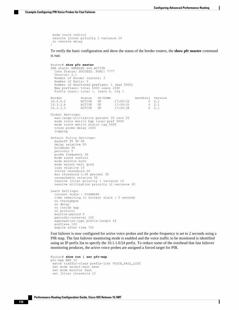
mode route control resolve jitter priority 1 variance 10 no resolve delay!
To verify the basic configuration and show the status of the border routers, the show pfr master commandis run:
Router# show pfr masterOER state: ENABLED and ACTIVE Conn Status: SUCCESS, PORT: 7777 Version: 2.1 Number of Border routers: 3 Number of Exits: 3 Number of monitored prefixes: 1 (max 5000) Max prefixes: total 5000 learn 2500 Prefix count: total 1, learn 0, cfg 1 Border Status UP/DOWN AuthFail Version10.4.4.2 ACTIVE UP 17:00:32 0 2.110.3.3.4 ACTIVE UP 17:00:35 0 2.110.3.3.3 ACTIVE UP 17:00:38 0 2.1 Global Settings: max-range-utilization percent 20 recv 20 mode route metric bgp local-pref 5000 mode route metric static tag 5000 trace probe delay 1000 logging Default Policy Settings: backoff 90 90 90 delay relative 50 holddown 90 periodic 0 probe frequency 56 mode route control mode monitor both mode select-exit good loss relative 10 jitter threshold 20 mos threshold 3.60 percent 30 unreachable relative 50 resolve jitter priority 1 variance 10 resolve utilization priority 12 variance 20 Learn Settings: current state : DISABLED time remaining in current state : 0 seconds no throughput no delay no inside bgp no protocol monitor-period 5 periodic-interval 120 aggregation-type prefix-length 24 prefixes 100 expire after time 720
Fast failover is now configured for active voice probes and the probe frequency is set to 2 seconds using aPfR map. The fast failover monitoring mode is enabled and the voice traffic to be monitored is identifiedusing an IP prefix list to specify the 10.1.1.0/24 prefix. To reduce some of the overhead that fast failovermonitoring produces, the active voice probes are assigned a forced target for PfR.
Router# show run | sec pfr-mappfr-map MAP 10 match traffic-class prefix-list VOICE_FAIL_LIST set mode select-exit best set mode monitor fast set jitter threshold 12
Configuring Advanced Performance Routing Example Configuring PfR Voice Probes for Fast Failover
Performance Routing Configuration Guide, Cisco IOS Release 15.1MT110

set active-probe jitter 120.120.120.1 target-port 20 codec g729a set probe frequency 2
The following output from the show pfr master prefixcommand when a prefix is specified with the policykeyword shows the policy configured for the prefix 10.1.1.0/24. Note that the mode monitor is set to fast,which automatically sets the select-exit to best, and allows the probe frequency to be set at 2.
Router# show pfr master prefix 10.1.1.0/24 policy* Overrides Default Policy Settingpfr-map MAP 10 sequence no. 8444249301975040, provider id 1, provider priority 30 host priority 0, policy priority 10, Session id 0 match ip prefix-lists: VOICE_FAIL_LIST backoff 90 90 90 delay relative 50 holddown 90 periodic 0 *probe frequency 2 mode route control *mode monitor fast *mode select-exit best loss relative 10 *jitter threshold 12 mos threshold 3.60 percent 30 unreachable relative 50 next-hop not set forwarding interface not set resolve jitter priority 1 variance 10 resolve utilization priority 12 variance 20 Forced Assigned Target List: active-probe jitter 10.120.120.1 target-port 20 codec g729a
After the master controller is configured for fast failover as shown in this task, and a traffic class goes outof policy, the logging output below shows that the traffic class represented by prefix 10.1.1.0/24 is routedby PfR through a new border router exit at interface 10.3.3.4 within 3 seconds. From the logging output, itappears that the traffic class moved to an out-of-policy state due to the jitter threshold being exceeded.
May 2 10:55:27.355: %OER_MC-5-NOTICE: Active ABS Jitter OOP Prefix 10.1.1.0/24,jitter 15, BR 10.4.4.2, i/f Et2/0May 2 10:55:27.367: %OER_MC-5-NOTICE: Route changed Prefix 10.1.1.0/24, BR 10.3.3.4,i/f Et5/0, Reason Jitter, OOP Reason Jitter
Example Configuring the Source Address of an Active ProbeThe following example, starting in global configuration mode, configures FastEthernet 0/0 as the active-probe source interface.
Router(config)# pfr border Router(config-pfr-br)# active-probe address source interface FastEthernet 0/0
Apply Policy Phase Tasks Examples• Example Configuring and Applying a PfR Policy to Learned Traffic Classes, page 112• Example Configuring and Applying a PfR Policy to Configured Traffic Classes, page 112• Example Preventing PfR Optimization of Learned Prefixes, page 112• Example Configuring Policy Rules for PfR Maps, page 113• Example Configuring Multiple PfR Policy Conflict Resolution, page 113• Example Configuring an Exit Link Load Balancing PfR Policy, page 113• Example Configuring Black Hole Routing Using a PfR Map, page 114• Example Configuring Sinkhole Routing Using a PfR Map, page 114
Apply Policy Phase Tasks ExamplesExample Configuring the Source Address of an Active Probe
Performance Routing Configuration Guide, Cisco IOS Release 15.1MT 111

Example Configuring and Applying a PfR Policy to Learned Traffic ClassesThe following example uses learned traffic classes and overwrites many of the default policy settings andconfigures the master controller to move traffic classes to the best available exit link when any of theconfigured or default policy settings exceed their thresholds:
enableconfigure terminalpfr master backoff 200 2000 200 delay threshold 2000 holddown 400 loss threshold 1500 periodic 180 unreachable threshold 1000 mode select-exit best end
Example Configuring and Applying a PfR Policy to Configured Traffic ClassesThe following example uses traffic classes filtered by a prefix list and an access list and overwrites some ofthe default policy settings. The policies are configured using two PfR maps that apply to different trafficclasses that represent voice traffic. The master controller is configured to move traffic classes to the first in-policy exit link when any of the configured or default policy settings exceed their thresholds.
enableconfigure terminalip prefix-list CONFIG_TRAFFIC_CLASS seq 10 permit 10.1.5.0/24ip access-list extended VOICE_TRAFFIC_CLASS permit udp any range 16384 32767 10.1.5.0 0.0.0.15 range 16384 32767 dscp ef exitpfr-map CONFIG_MAP 10 match ip address prefix-list CONFIG_TRAFFIC_CLASS set backoff 100 1000 100 set delay threshold 1000 set loss relative 25 set periodic 360 set unreachable relative 20 exitpfr-map VOICE_MAP 10 match ip address access-list VOICE_TRAFFIC_CLASS set active-probe jitter 10.1.5.1 target-port 2000 codec g729a set probe-frequency 20 set jitter threshold 30 set mos threshold 4.0 percent 25 set mode select-exit good end
Example Preventing PfR Optimization of Learned PrefixesThe following example shows how to configure PfR to prevent specified prefixes being optimized. In thisexample, an IP prefix list is created with two entries for different prefixes that are not to be optimized. APfR map is configured with two entries in a sequence that will prevent PfR from optimizing the prefixesspecified in the prefix list, although the prefixes may be learned. If the sequence numbers of the PfR mapentries are reversed, PfR will learn and attempt to optimize the prefixes.
enableconfigure terminalip prefix-list DENY_PREFIX deny 172.17.10.0/24ip prefix-list DENY_PREFIX deny 172.19.10.0/24pfr-map DENY_PREFIX_MAP 10 match ip address prefix-list DENY_PREFIX
Configuring Advanced Performance Routing Example Configuring and Applying a PfR Policy to Learned Traffic Classes
Performance Routing Configuration Guide, Cisco IOS Release 15.1MT112

exitpfr-map DENY_PREFIX_MAP 20 match pfr learn throughput end
Example Configuring Policy Rules for PfR MapsThe following example shows how to configure the policy-rules (PfR) command to apply the PfR mapconfiguration named BLUE under PfR master controller mode:
enableconfigure terminalpfr-map BLUE 10 match pfr learn delay set loss relative 90 exit pfr master policy-rules BLUE exit
Example Configuring Multiple PfR Policy Conflict ResolutionThe following example configures a PfR resolve policy that sets delay to the highest priority, followed byloss, and then utilization. The delay policy is configured to allow a 20 percent variance, the loss policy isconfigured to allow a 30 percent variance, and the utilization policy is configured to allow a 10 percentvariance.
enableconfigure terminalpfr master resolve delay priority 1 variance 20 resolve loss priority 2 variance 30 resolve utilization priority 3 variance 10 end
Example Configuring an Exit Link Load Balancing PfR PolicyThe following example configures a PfR load balancing policy for traffic class flows over the border routerexit links. This example task is performed at the master controller and configures an exit link utilizationrange and an exit link utilization threshold with policy priorities set for utilization and range policies.Performance policies, delay and loss, are disabled. PfR uses both the utilization and range thresholds toload balance the traffic flow over the exit links.
enableconfigure terminalpfr master max-range-utilization percentage 25 mode select-exit best resolve range priority 1 resolve utilization priority 2 variance 15 no resolve delay no resolve loss border 10.1.4.1 interface Ethernet 1/0 external max-xmit-utilization absolute 10000 exit exit border 10.1.2.1 interface Ethernet 1/0 external max-xmit-utilization absolute 10000 end
Configuring Advanced Performance RoutingExample Configuring Policy Rules for PfR Maps
Performance Routing Configuration Guide, Cisco IOS Release 15.1MT 113

Example Configuring Black Hole Routing Using a PfR MapThe following example creates a PfR map named BLACK_HOLE_MAP that matches traffic defined in theIP prefix list named PREFIX_BLACK_HOLE. The PfR map filters packets to be forwarded to a nullinterface, meaning that the packets are discarded in a “black hole.” The prefix list is configured after an IPprefix is identified as the source of the attack on the network.
enableconfigure terminalip prefix-list PREFIX_BLACK_HOLE seq 10 permit 10.1.5.0/24pfr-map BLACK_HOLE_MAP 10 match ip address prefix-list PREFIX_BLACK_HOLE set interface null0 end
Example Configuring Sinkhole Routing Using a PfR MapThe following example creates a PfR map named SINK_HOLE_MAP that matches traffic defined in the IPprefix list named PREFIX_SINK_HOLE. The PfR map filters packets to be forwarded to a next hop. Thenext hop is a router where the packets can be stored, analyzed, or discarded (the sinkhole analogy). Theprefix list is configured after an IP prefix is identified as the source of an attack on the network.
enableconfigure terminalip prefix-list PREFIX_SINK_HOLE seq 10 permit 10.1.5.0/24pfr-map SINK_HOLE_MAP 10 match ip address prefix-list PREFIX_SINK_HOLE set next-hop 10.1.1.3 end
Enforce Phase Tasks Examples• Example Setting a Tag Value for Injected PfR Static Routes, page 114• Example Setting a BGP Local Preference Value for PfR Controlled BGP Routes, page 114• Example Controlling Application Traffic, page 115
Example Setting a Tag Value for Injected PfR Static RoutesThe following example shows how to set a tag value for an injected static route to allow the routes to beuniquely identified. A static route may be injected by PfR to control the traffic defined by a traffic classwhen it goes out-of-policy. By default, PfR uses a tag value of 5000 for injected static routes. In this task,the PfR route control mode is configured globally with the mode (PfR) command in PfR master controllerconfiguration mode and any injected static routes will be tagged with a value of 15000.
Router(config)# pfr master Router(config-pfr-mc)# mode route control Router(config-pfr-mc)# mode route metric static tag 15000Router(config-pfr-mc)# end
Example Setting a BGP Local Preference Value for PfR Controlled BGP RoutesThe following example shows how to set a BGP local preference attribute value. PfR uses the BGPLocal_Pref value to influence the BGP best path selection on internal BGP (iBGP) neighbors as a method
Enforce Phase Tasks Examples Example Configuring Black Hole Routing Using a PfR Map
Performance Routing Configuration Guide, Cisco IOS Release 15.1MT114

of enforcing exit link selection. By default, PfR uses a Local_Pref value of 5000. In this task, route controlis enabled for traffic matching a prefix list and the BGP local preference value of 60000 is set.
Router(config)# pfr-map BLUE 10 Router(config-pfr-map)# match ip address prefix-list BLUERouter(config-pfr-map)# set mode route control Router(config-pfr-map)# set mode route metric bgp local-pref 60000Router(config-pfr-map)# end
Example Controlling Application TrafficThe following example shows how to use policy-based routing (PBR) to allow PfR to control specifiedapplication traffic classes. Application traffic such as Telnet traffic is delay sensitive. Long TCP delays canmake Telnet sessions difficult to use. This example is configured on a master controller and matches Telnettraffic sourced from the 192.168.1.0/24 network and applies a policy to ensure it is sent out through exitlinks with that have a response time that is equal to or less than 30 milliseconds:
Router(config)# ip access-list extended TELNET Router(config-ext-nacl)# permit tcp 192.168.1.0 0.0.0.255 any eq telnet Router(config-ext-nacl)# exit Router(config)# pfr-map SENSITIVERouter(config-route-map)# match ip address access-list TELNET Router(config-route-map)# set mode route controlRouter(config-route-map)# set delay threshold 30 Router(config-route-map)# set resolve delay priority 1 variance 20 Router(config-route-map)# end
The following example shows TCP application traffic filtered based on port 23 (Telnet):
Router# show pfr master appl tcp 23 23 dst policy Prefix Appl Prot Port Port Type Policy --------------------------------------------------------------------------------10.1.1.0/24 tcp [23, 23] src 10
Verify Phase Task Example• Example Manually Verifying the PfR Route Control Changes, page 115
Example Manually Verifying the PfR Route Control ChangesThe following examples show how to manually verify that the traffic control implemented by the PfRenforce phase actually changes the traffic flow and brings the OOP event to be in-policy. On the mastercontroller the show logging command is used to display the state of system logging (syslog) and thecontents of the standard system logging buffer. Using optional delimiters, the logging buffer can bedisplayed with PfR messages for a specific prefix. The show pfr master prefix command displays thestatus of monitored prefixes. On the border router, the show pfr border routes command displaysinformation about PfR controlled BGP or static routes on the border router. For example output of thesecommands, see the "Manually Verifying the PfR Route Enforce Changes" section.
Master Controller
Router# show logging | i 10.1.1.0Router# show pfr master prefix 10.1.1.0Router# end
Verify Phase Task ExampleExample Controlling Application Traffic
Performance Routing Configuration Guide, Cisco IOS Release 15.1MT 115

Border Router
Router# show pfr border routes staticRouter# show pfr border routes bgpRouter# end
Where to Go NextFor more detailed concepts, see the “Understanding Performance Routing” module.
For information about other Performance Routing features or general conceptual material, see thedocuments in the “Related Documents” section.
Additional ReferencesRelated Documents
Related Topic Document Title
Cisco IOS commands Cisco IOS Master Commands List, All Releases
Cisco PfR commands: complete command syntax,command mode, command history, defaults, usageguidelines and examples
Cisco IOS Performance Routing CommandReference
Basic PfR configuration "Configuring Basic Performance Routing" module
Concepts required to understand the PerformanceRouting operational phases
"Understanding Performance Routing" module
Advanced PfR configuration "Configuring Advanced Performance Routing"module
IP SLAs overview IP SLAs Configuration Guide
Technical Assistance
Description Link
The Cisco Support and Documentation websiteprovides online resources to downloaddocumentation, software, and tools. Use theseresources to install and configure the software andto troubleshoot and resolve technical issues withCisco products and technologies. Access to mosttools on the Cisco Support and Documentationwebsite requires a Cisco.com user ID andpassword.
http://www.cisco.com/cisco/web/support/index.html
Configuring Advanced Performance Routing Where to Go Next
Performance Routing Configuration Guide, Cisco IOS Release 15.1MT116

Feature Information for Configuring Advanced PerformanceRouting
The following table provides release information about the feature or features described in this module.This table lists only the software release that introduced support for a given feature in a given softwarerelease train. Unless noted otherwise, subsequent releases of that software release train also support thatfeature.
Use Cisco Feature Navigator to find information about platform support and Cisco software image support.To access Cisco Feature Navigator, go to www.cisco.com/go/cfn. An account on Cisco.com is not required.
Table 4 Feature Information for Configuring Advanced Performance Routing
Feature Name Releases Feature Information
Optimized Edge Routing 12.3(8)T 12.2(33)SRB OER was introduced.Performance Routing is anextension of OER.
OER Support for Policy-RulesConfiguration
12.3(11)T 12.2(33)SRB The OER Support for Policy-Rules Configuration featureintroduced the capability to selecta PfR map and apply theconfiguration under PfR mastercontroller configuration mode,providing an improved method toswitch between predefined PfRmaps.
The following commands wereintroduced or modified by thisfeature: policy-rules(PfR).
expire after command3 12.3(14)T 12.2(33)SRB Theexpire after (PfR) commandis used to set an expiration periodfor learned prefixes. By default,the master controller removesinactive prefixes from the centralpolicy database as memory isneeded. This command allowsyou to refine this behavior bysetting a time or session basedlimit. The time based limit isconfigured in minutes. Thesession based limit is configuredfor the number of monitor periods(or sessions).
3 This is a minor enhancement. Minor enhancements are not typically listed in Feature Navigator.
Configuring Advanced Performance RoutingFeature Information for Configuring Advanced Performance Routing
Performance Routing Configuration Guide, Cisco IOS Release 15.1MT 117

Feature Name Releases Feature Information
OER Active Probe SourceAddress
12.4(2)T 12.2(33)SRB The OER Active Probe SourceAddress feature allows you toconfigure a specific exit interfaceon the border router as the sourcefor active probes.
The active-probe address source(PfR) command was introducedby this feature.
OER Application-AwareRouting: PBR
12.4(2)T 12.2(33)SRB The OER Application-AwareRouting: PBR feature introducesthe capability to optimize IPtraffic based on the type ofapplication that is carried by themonitored prefix. Independentpolicy configuration is applied tothe subset (application) of traffic.
The following commands wereintroduced or modified by thisfeature: debug pfr border pbr,debug pfr master prefix, matchip address (PfR),show pfrmaster active-probes, and showpfr master appl.
Configuring Advanced Performance Routing Feature Information for Configuring Advanced Performance Routing
Performance Routing Configuration Guide, Cisco IOS Release 15.1MT118
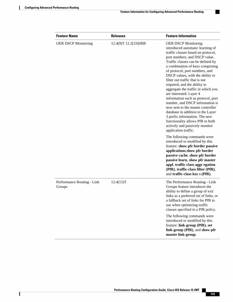
Feature Name Releases Feature Information
OER DSCP Monitoring 12.4(9)T 12.2(33)SRB OER DSCP Monitoringintroduced automatic learning oftraffic classes based on protocol,port numbers, and DSCP value.Traffic classes can be defined bya combination of keys comprisingof protocol, port numbers, andDSCP values, with the ability tofilter out traffic that is notrequired, and the ability toaggregate the traffic in which youare interested. Layer 4information such as protocol, portnumber, and DSCP information isnow sent to the master controllerdatabase in addition to the Layer3 prefix information. The newfunctionality allows PfR to bothactively and passively monitorapplication traffic.
The following commands wereintroduced or modified by thisfeature: show pfr border passiveapplications,show pfr borderpassive cache, show pfr borderpassive learn, show pfr masterappl, traffic-class aggr egation(PfR), traffic-class filter (PfR),and traffic-class key s (PfR).
Performance Routing - LinkGroups
12.4(15)T The Performance Routing - LinkGroups feature introduces theability to define a group of exitlinks as a preferred set of links, ora fallback set of links for PfR touse when optimizing trafficclasses specified in a PfR policy.
The following commands wereintroduced or modified by thisfeature: link-group (PfR), setlink-group (PfR), and show pfrmaster link-group.
Configuring Advanced Performance RoutingFeature Information for Configuring Advanced Performance Routing
Performance Routing Configuration Guide, Cisco IOS Release 15.1MT 119

Feature Name Releases Feature Information
Support for Fast FailoverMonitoring4
12.4(15)T Fast Failover Monitoringintroduced the ability to configurea fast monitoring mode. In fastfailover monitoring mode, allexits are continuously probedusing active monitoring andpassive monitoring. The probefrequency can be set to a lowerfrequency in fast failovermonitoring mode than for othermonitoring modes, to allow afaster failover capability. Fastfailover monitoring can be usedwith all types of active probes:ICMP echo, jitter, TCPconnection, and UDP echo.
The following commands weremodified by this feature: mode(PfR), set mode (PfR).
Cisco and the Cisco Logo are trademarks of Cisco Systems, Inc. and/or its affiliates in the U.S. and othercountries. A listing of Cisco's trademarks can be found at www.cisco.com/go/trademarks. Third partytrademarks mentioned are the property of their respective owners. The use of the word partner does notimply a partnership relationship between Cisco and any other company. (1005R)
Any Internet Protocol (IP) addresses and phone numbers used in this document are not intended to beactual addresses and phone numbers. Any examples, command display output, network topology diagrams,and other figures included in the document are shown for illustrative purposes only. Any use of actual IPaddresses or phone numbers in illustrative content is unintentional and coincidental.
4 This is a minor enhancement. Minor enhancements are not typically listed in Feature Navigator.
Configuring Advanced Performance Routing
Performance Routing Configuration Guide, Cisco IOS Release 15.1MT120

BGP Inbound Optimization Using PerformanceRouting
The PfR BGP Inbound Optimization feature introduced support for the best entrance selection for trafficthat originates from prefixes outside an autonomous system destined for prefixes inside the autonomoussystem. External BGP (eBGP) advertisements from an autonomous system to an Internet service provider(ISP) can influence the entrance path for traffic entering the network. PfR uses eBGP advertisements tomanipulate the best entrance selection.
• Finding Feature Information, page 121• Information About BGP Inbound Optimization Using Performance Routing, page 121• How to Configure BGP Inbound Optimization Using Performance Routing, page 125• Configuration Examples for BGP Inbound Optimization Using Performance Routing, page 137• Additional References, page 139• Feature Information for BGP Inbound Optimization Using Performance Routing, page 140
Finding Feature InformationYour software release may not support all the features documented in this module. For the latest featureinformation and caveats, see the release notes for your platform and software release. To find informationabout the features documented in this module, and to see a list of the releases in which each feature issupported, see the Feature Information Table at the end of this document.
Use Cisco Feature Navigator to find information about platform support and Cisco software image support.To access Cisco Feature Navigator, go to www.cisco.com/go/cfn. An account on Cisco.com is not required.
Information About BGP Inbound Optimization UsingPerformance Routing
• BGP Inbound Optimization, page 122
• Prefix Traffic Class Learning Using PfR, page 122
• PfR Link Utilization Measurement, page 122
• PfR Link Policies, page 123
• PfR Entrance Link Selection Control Techniques, page 124
• PfR Map Operation for Inside Prefixes, page 125
Performance Routing Configuration Guide, Cisco IOS Release 15.1MT 121
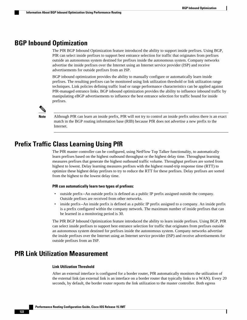
BGP Inbound OptimizationThe PfR BGP Inbound Optimization feature introduced the ability to support inside prefixes. Using BGP,PfR can select inside prefixes to support best entrance selection for traffic that originates from prefixesoutside an autonomous system destined for prefixes inside the autonomous system. Company networksadvertise the inside prefixes over the Internet using an Internet service provider (ISP) and receiveadvertisements for outside prefixes from an ISP.
BGP inbound optimization provides the ability to manually configure or automatically learn insideprefixes. The resulting prefixes can be monitored using link utilization threshold or link utilization rangetechniques. Link policies defining traffic load or range performance characteristics can be applied againstPfR-managed entrance links. BGP inbound optimization provides the ability to influence inbound traffic bymanipulating eBGP advertisements to influence the best entrance selection for traffic bound for insideprefixes.
Note Although PfR can learn an inside prefix, PfR will not try to control an inside prefix unless there is an exactmatch in the BGP routing information base (RIB) because PfR does not advertise a new prefix to theInternet.
Prefix Traffic Class Learning Using PfRThe PfR master controller can be configured, using NetFlow Top Talker functionality, to automaticallylearn prefixes based on the highest outbound throughput or the highest delay time. Throughput learningmeasures prefixes that generate the highest outbound traffic volume. Throughput prefixes are sorted fromhighest to lowest. Delay learning measures prefixes with the highest round-trip response time (RTT) tooptimize these highest delay prefixes to try to reduce the RTT for these prefixes. Delay prefixes are sortedfrom the highest to the lowest delay time.
PfR can automatically learn two types of prefixes:
• outside prefix--An outside prefix is defined as a public IP prefix assigned outside the company.Outside prefixes are received from other networks.
• inside prefix--An inside prefix is defined as a public IP prefix assigned to a company. An inside prefixis a prefix configured within the company network. The maximum number of inside prefixes that canbe learned in a monitoring period is 30.
The PfR BGP Inbound Optimization feature introduced the ability to learn inside prefixes. Using BGP, PfRcan select inside prefixes to support best entrance selection for traffic that originates from prefixes outsidean autonomous system destined for prefixes inside the autonomous system. Company networks advertisethe inside prefixes over the Internet using an Internet service provider (ISP) and receive advertisements foroutside prefixes from an ISP.
PfR Link Utilization Measurement
Link Utilization Threshold
After an external interface is configured for a border router, PfR automatically monitors the utilization ofthe external link (an external link is an interface on a border router that typically links to a WAN). Every 20seconds, by default, the border router reports the link utilization to the master controller. Both egress
BGP Inbound Optimization Information About BGP Inbound Optimization Using Performance Routing
Performance Routing Configuration Guide, Cisco IOS Release 15.1MT122

(transmitted) and ingress (received) traffic utilization values are reported to the master controller. If the exitor entrance link utilization is above the default threshold of 75 percent, the exit or entrance link is in anOOP state and PfR starts the monitoring process to find an alternative link for the traffic class. The linkutilization threshold can be manually configured either as an absolute value in kilobytes per second (kbps)or as a percentage.
Link Utilization Range
PfR can also be configured to calculate the range of utilization over all the links. Both egress (transmitted)and ingress (received) traffic utilization values are reported to the master controller. In the figure belowthere are two border routers with exits links to the Internet through two ISPs. The master controllerdetermines which link on one of the border routers--either BR1 or BR2 in the figure below--is used by atraffic class.
Figure 10 PfR network diagram
170913
ISP1/WAN1
ISP2/WAN2
MC
BR2
BR1
PfR range functionality attempts to keep the exit or entrance links within a utilization range, relative toeach other to ensure that the traffic load is distributed. The range is specified as a percentage and isconfigured on the master controller to apply to all the exit or entrance links on border routers managed bythe master controller. For example, if the range is specified as 25 percent, and the utilization of the exit linkat BR1 (in the figure above) is 70 percent, then if the utilization of the exit link at BR2 (in the figure above)falls to 40 percent, the percentage range between the two exit links will be more than 25 percent and PfRwill attempt to move some traffic classes to use the exit link at BR1 to even the traffic load. If BR1 (in thefigure above) is being configured as an entrance link, the link utilization range calculations work in thesame way as for an exit link, except that the utilization values are for received traffic, not transmittedtraffic.
PfR Link PoliciesPfR link policies are a set of rules that are applied against PfR-managed external links (an external link isan interface on a border router on the network edge). Link policies define the desired performancecharacteristics of the links. Instead of defining the performance of an individual traffic class entry that usesthe link (as in traffic class performance policies), link policies are concerned with the performance of thelink as a whole.
The BGP Inbound Optimization feature introduced support for selected entrance (ingress) link policies.
The following performance characteristics are managed by link policies:
• Traffic Load (Utilization)• Range• Cost--Cost policies are not supported by the BGP Inbound Optimization feature.For more details about
cost policies, see the "Configuring Performance Routing Cost Policies" module.
PfR Link PoliciesInformation About BGP Inbound Optimization Using Performance Routing
Performance Routing Configuration Guide, Cisco IOS Release 15.1MT 123

Traffic Load
A traffic load (also referred to as utilization) policy consists of an upper threshold on the amount of trafficthat a specific link can carry. Cisco IOS PfR supports per traffic class load distribution. Every 20 seconds,by default, the border router reports the link utilization to the master controller, after an external interface isconfigured for a border router. Both exit link and entrance link traffic load thresholds can be configured asan PfR policy. If the exit or entrance link utilization is above the configured threshold, or the defaultthreshold of 75-percent, the exit or entrance link is in an OOP state and PfR starts the monitoring process tofind an alternative link for the traffic class. The link utilization threshold can be manually configured eitheras an absolute value in kilobytes per second (kbps) or as a percentage. A load utilization policy for anindividual interface is configured on the master controller under the border router configuration.
Tip When configuring load distribution, we recommend that you set the interface load calculation on externalinterfaces to 30-second intervals with the load-interval interface configuration command. The defaultcalculation interval is 300 seconds. The load calculation is configured under interface configuration modeon the border router. This configuration is not required, but it is recommended to allow Cisco IOS PfR torespond as quickly as possible to load distribution issues.
Range
A range policy is defined to maintain all links within a certain utilization range, relative to each other inorder to ensure that the traffic load is distributed. For example, if a network has multiple exit links, andthere is no financial reason to choose one link over another, the optimal choice is to provide an even loaddistribution across all links. The load-sharing provided by traditional routing protocols is not always evenlydistributed, because the load-sharing is flow-based rather than performance- or policy-based. Cisco IOSPfR range functionality allows you to configure PfR to maintain the traffic utilization on a set of linkswithin a certain percentage range of each other. If the difference between the links becomes too great, PfRwill attempt to bring the link back to an in-policy state by distributing traffic classes among the availablelinks. The master controller sets the maximum range utilization to 20-percent for all PfR-managed links bydefault, but the utilization range can be configured using a maximum percentage value. Both exit link andentrance link utilization ranges can be configured as a PfR policy.
PfR Entrance Link Selection Control TechniquesThe PfR BGP inbound optimization feature introduced the ability to influence inbound traffic. A networkadvertises reachability of its inside prefixes to the Internet using eBGP advertisements to its ISPs. If thesame prefix is advertised to more than one ISP, then the network is multihoming. PfR BGP inboundoptimization works best with multihomed networks, but it can also be used with a network that has multipleconnections to the same ISP. To implement BGP inbound optimization, PfR manipulates eBGPadvertisements to influence the best entrance selection for traffic bound for inside prefixes. The benefit ofimplementing the best entrance selection is limited to a network that has more than one ISP connection.
To enforce an entrance link selection, PfR offers the following methods:
BGP Autonomous System Number Prepend
After PfR selects a best entrance for an inside prefix, extra autonomous system hops (up to a maximum ofsix) are prepended to the inside prefix BGP advertisement over the other entrances. The extra autonomoussystem hops on the other entrances increase the probability that the best entrance will be used for the insideprefix. This is the default method PfR uses to control an inside prefix, and no user configuration is required.
PfR Entrance Link Selection Control Techniques Information About BGP Inbound Optimization Using Performance Routing
Performance Routing Configuration Guide, Cisco IOS Release 15.1MT124
BGP Autonomous System Number Community Prepend
After PfR selects a best entrance for an inside prefix, a BGP prepend community is attached to the insideprefix BGP advertisement from the network to another autonomous system such as an ISP. The BGPprepend community will increase the number of autonomous system hops in the advertisement of the insideprefix from the ISP to its peers. Autonomous system prepend BGP community is the preferred method tobe used for PfR BGP inbound optimization because there is no risk of the local ISP filtering the extraautonomous system hops. There are some issues, for example, not all ISPs support the BGP prependcommunity, ISP policies may ignore or modify the autonomous system hops, and a transit ISP may filterthe autonomous system path. If you use this method of inbound optimization and a change is made to anautonomous system, you must issue an outbound reconfiguration using the clear ip bgp command.
PfR Map Operation for Inside PrefixesThe operation of a PfR map is similar to the operation of a route-map. A PfR map is configured to select anIP prefix list or PfR learn policy using a match clause and then to apply PfR policy configurations using aset clause. The PfR map is configured with a sequence number like a route-map, and the PfR map with thelowest sequence number is evaluated first.
The BGP Inbound Optimization feature introduced the inside keyword to the match ip address (PfR)command to identify inside prefixes. Inbound BGP only supports the passive mode which results in someconfiguration restrictions when using a PfR map. The following commands are not supported in a PfR mapfor inbound BGP; set active-probe, set interface, set mode monitor, set mode verify bidirectional, setmos threshold, set nexthop, set periodic, set probe frequency, and set traceroute reporting.
Note Match precedence priority is not supported in PfR maps.
How to Configure BGP Inbound Optimization UsingPerformance Routing
• Configuring PfR to Automatically Learn Traffic Classes Using Inside Prefixes, page 125• Manually Selecting Inside Prefixes for PfR Monitoring, page 128• Modifying the PfR Link Utilization for Inbound Traffic, page 129• Modifying the PfR Entrance Link Utilization Range, page 131• Configuring and Applying a PfR Policy to Learned Inside Prefixes, page 132• Configuring and Applying a PfR Policy to Configured Inside Prefixes, page 135
Configuring PfR to Automatically Learn Traffic Classes Using InsidePrefixes
Perform this task at a PfR master controller to configure PfR to automatically learn inside prefixes to beused as traffic classes. The traffic classes are entered in the MTC list. This task introduces the inside bgp(PfR) command used in PfR Top Talker and Top Delay configuration mode. This task configures automaticprefix learning of the inside prefixes (prefixes within the network). Optional configuration parameters suchas learning period timers, maximum number of prefixes, and an expiration time for MTC list entries arealso shown.
PfR Map Operation for Inside PrefixesHow to Configure BGP Inbound Optimization Using Performance Routing
Performance Routing Configuration Guide, Cisco IOS Release 15.1MT 125

Before configuring this task, BGP peering for internal and external BGP neighbors must be configured.
SUMMARY STEPS
1. enable
2. configure terminal
3. pfr master
4. learn
5. inside bgp
6. monitor-period minutes
7. periodic-interval minutes
8. prefixes number
9. expire after session number | time minutes
10. end
DETAILED STEPS
Command or Action Purpose
Step 1 enable
Example:
Router> enable
Enables privileged EXEC mode.
• Enter your password if prompted.
Step 2 configure terminal
Example:
Router# configure terminal
Enters global configuration mode.
Step 3 pfr master
Example:
Router(config)# pfr master
Enters PfR master controller configuration mode to configure a router as amaster controller and to configure global operations and policies.
Step 4 learn
Example:
Router(config-pfr-mc)# learn
Enters PfR Top Talker and Top Delay learning configuration mode toconfigure prefix learning policies and timers.
BGP Inbound Optimization Using Performance Routing How to Configure BGP Inbound Optimization Using Performance Routing
Performance Routing Configuration Guide, Cisco IOS Release 15.1MT126

Command or Action Purpose
Step 5 inside bgp
Example:
Router(config-pfr-mc-learn)# inside bgp
Learns prefixes inside the network.
Step 6 monitor-period minutes
Example:
Router(config-pfr-mc-learn)# monitor-period 10
(Optional) Sets the time period that a PfR master controller learns trafficflows.
• The default learning period is 5 minutes.• The length of time between monitoring periods is configured with the
periodic-interval command.• The number of prefixes that are learned is configured with the prefixes
command.• The example sets the length of each monitoring period to 10 minutes.
Step 7 periodic-interval minutes
Example:
Router(config-pfr-mc-learn)# periodic-interval 20
(Optional) Sets the time interval between prefix learning periods.
• By default, the interval between prefix learning periods is 120 minutes.• The example sets the time interval between monitoring periods to 20
minutes.
Step 8 prefixes number
Example:
Router(config-pfr-mc-learn)# prefixes 30
(Optional) Sets the number of prefixes that the master controller will learnduring the monitoring period.
• By default, the top 100 traffic flows are learned.• The example configures a master controller to learn 30 prefixes during
each monitoring period.
Note The maximum number of inside prefixes that can be learned in amonitoring period is 30.
Step 9 expire after session number | time minutes
Example:
Router(config-pfr-mc-learn)# expire after session 100
(Optional) Sets the length of time that learned prefixes are kept in the centralpolicy database.
• The session keyword configures learned prefixes to be removed afterthe specified number of monitoring periods have occurred.
• The time keyword configures learned prefixes to be removed after thespecified time period. The time value is entered in minutes.
• The example configures learned prefixes to be removed after 100monitoring periods.
Step 10 end
Example:
Router(config-pfr-mc-learn)# end
Exits PfR Top Talker and Top Delay learning configuration mode, andenters privileged EXEC mode.
BGP Inbound Optimization Using Performance RoutingHow to Configure BGP Inbound Optimization Using Performance Routing
Performance Routing Configuration Guide, Cisco IOS Release 15.1MT 127

Manually Selecting Inside Prefixes for PfR MonitoringThe PfR BGP inbound optimization feature introduced the ability to manually select inside prefixes tosupport best entrance selection for traffic that originates from prefixes outside an autonomous systemdestined for prefixes inside the autonomous system. Perform this task to manually select inside prefixes forPfR monitoring by creating an IP prefix list to define the inside prefix or prefix range. The prefix list is thenimported into the Monitored Traffic Class (MTC) list by configuring a match clause in a PfR map.
SUMMARY STEPS
1. enable
2. configure terminal
3. ip prefix-list list-name [seq seq-value]{deny network/length | permit network/length}[le le-value]
4. pfr-map map-name sequence-number
5. match ip address prefix-list name [inside]
6. end
DETAILED STEPS
Command or Action Purpose
Step 1 enable
Example:
Router> enable
Enables privileged EXEC mode.
• Enter your password if prompted.
Step 2 configure terminal
Example:
Router# configure terminal
Enters global configuration mode.
Step 3 ip prefix-list list-name [seq seq-value]{deny network/length | permit network/length}[le le-value]
Example:
Router(config)# ip prefix-list INSIDE_PREFIXES seq 20 permit 192.168.1.0/24
Creates a prefix list to manually select prefixes for monitoring.
• A master controller can monitor and control an exact prefix of any lengthincluding the default route. The master controller acts only on theconfigured prefix.
• A master controller can monitor and control an inclusive prefix using thele 32 option. The master controller acts on the configured prefix andforces any more specific prefixes in the RIB to use the same exit.
Note This option should be applied carefully. It is not needed in typicaldeployments.
• The example creates an IP prefix list for PfR to monitor and control theexact prefix, 192.168.1.0/24
Manually Selecting Inside Prefixes for PfR Monitoring How to Configure BGP Inbound Optimization Using Performance Routing
Performance Routing Configuration Guide, Cisco IOS Release 15.1MT128

Command or Action Purpose
Step 4 pfr-map map-name sequence-number
Example:
Router(config)# pfr-map INSIDE_MAP 10
Enters PfR map configuration mode to create or configure a PfR map.
• PfR map operation is similar to that of route maps.• Only a single match clause can be configured for each PfR map sequence.• Common and deny sequences should be applied to lowest PfR map
sequence for best performance.• The example creates a PfR map named INSIDE_MAP.
Step 5 match ip address prefix-list name [inside]
Example:
Router(config-pfr-map)# match ip address prefix-list INSIDE_PREFIXES inside
Creates a prefix list match clause entry in a PfR map to apply PfR policies.
• This command supports IP prefix lists only.• Use the inside keyword to identify inside prefixes.• The example creates a match clause to use the prefix list
INSIDE_PREFIXES to specify that inside prefixes must be matched.
Step 6 end
Example:
Router(config-pfr-map)# end
Exits PfR map configuration mode and returns to privileged EXEC mode.
Modifying the PfR Link Utilization for Inbound TrafficThe BGP Inbound Optimization feature introduced the ability to report inbound traffic utilization to themaster controller. Perform this task at the master controller to modify the PfR entrance (inbound) linkutilization threshold. After an external interface has been configured for a border router, PfR automaticallymonitors the utilization of entrance links on a border router every 20 seconds. The utilization is reportedback to the master controller and, if the utilization exceeds 75 percent, PfR selects another entrance link fortraffic classes on that link. An absolute value in kilobytes per second (kbps), or a percentage, can bespecified.
SUMMARY STEPS
1. enable
2. configure terminal
3. pfr master
4. border ip-address [key-chain key-chain-name]
5. interface type number external
6. maximum utilization receive {absolute kbps | percent percentage}
7. end
Modifying the PfR Link Utilization for Inbound TrafficHow to Configure BGP Inbound Optimization Using Performance Routing
Performance Routing Configuration Guide, Cisco IOS Release 15.1MT 129

DETAILED STEPS
Command or Action Purpose
Step 1 enable
Example:
Router> enable
Enables privileged EXEC mode.
• Enter your password if prompted.
Step 2 configure terminal
Example:
Router# configure terminal
Enters global configuration mode.
Step 3 pfr master
Example:
Router(config)# pfr master
Enters PfR master controller configuration mode to configure a router as a mastercontroller and to configure global operations and policies.
Step 4 border ip-address [key-chain key-chain-name]
Example:
Router(config-pfr-mc)# border 10.1.1.2
Enters PfR-managed border router configuration mode to establish communicationwith a border router.
• An IP address is configured to identify the border router.• At least one border router must be specified to create an PfR-managed
network. A maximum of ten border routers can be controlled by a singlemaster controller.
Note The key-chain keyword and key-chain-name argument must be enteredwhen a border router is initially configured. However, this keyword isoptional when reconfiguring an existing border router.
Step 5 interface type number external
Example:
Router(config-pfr-mc-br)# interface GigabitEthernet 0/0/0 external
Configures a border router interface as an PfR-managed external interface andenters PfR border exit interface configuration mode.
• External interfaces are used to forward traffic and for active monitoring.• A minimum of two external border router interfaces are required in a PfR-
managed network. At least one external interface must be configured on eachborder router. A maximum of 20 external interfaces can be controlled by singlemaster controller.
Note Entering the interface command without the external orinternal keywordplaces the router in global configuration mode and not PfR border exitconfiguration mode. The no form of this command should be appliedcarefully so that active interfaces are not removed from the routerconfiguration.
BGP Inbound Optimization Using Performance Routing How to Configure BGP Inbound Optimization Using Performance Routing
Performance Routing Configuration Guide, Cisco IOS Release 15.1MT130

Command or Action Purpose
Step 6 maximum utilization receive{absolute kbps | percentpercentage}
Example:
Router(config-pfr-mc-br-if)# maximum utilization receive percent 90
Sets the maximum receive utilization threshold for the configured PfR-managedlink interface.
• Use the absolute keyword and kbps argument to specify the absolute thresholdvalue, in kilobytes per second (kbps), of the throughput for all the entrancelinks.
• Use the percent keyword and percentage argument to specify the maximumutilization threshold as a percentage of bandwidth received by all the entrancelinks.
• In this example, the maximum utilization threshold of inbound traffic on thisentrance link on the border router must be 90 percent, or less.
Step 7 end
Example:
Router(config-pfr-mc-br-if)# end
Exits PfR border exit interface configuration mode and returns to privileged EXECmode.
Modifying the PfR Entrance Link Utilization RangePerform this task at the master controller to modify the maximum entrance link utilization range over allthe border routers. By default, PfR automatically monitors the utilization of external links on a borderrouter every 20 seconds, and the border router reports the utilization to the master controller. The BGPInbound Optimization feature introduced the ability to report inbound traffic utilization to the mastercontroller, and to specify a link utilization range for entrance links.
In this task, if the utilization range between all the entrance links exceeds 20 percent, the master controllertries to equalize the traffic load by moving some traffic classes to another entrance link. The maximumutilization range is configured as a percentage.
PfR uses the maximum utilization range to determine if links are in-policy. In this task, PfR will equalizeinbound traffic across all entrance links by moving traffic classes from overutilized or out-of-policy exits toin-policy exits.
SUMMARY STEPS
1. enable
2. configure terminal
3. pfr master
4. max range receive percent percentage
5. end
Modifying the PfR Entrance Link Utilization RangeHow to Configure BGP Inbound Optimization Using Performance Routing
Performance Routing Configuration Guide, Cisco IOS Release 15.1MT 131

DETAILED STEPS
Command or Action Purpose
Step 1 enable
Example:
Router> enable
Enables privileged EXEC mode.
• Enter your password if prompted.
Step 2 configure terminal
Example:
Router# configure terminal
Enters global configuration mode.
Step 3 pfr master
Example:
Router(config)# pfr master
Enters PfR master controller configuration mode to configure a router asa master controller and to configure global operations and policies.
Step 4 max range receive percent percentage
Example:
Router(config-pfr-mc)# max range receive percent 20
Specifies the upper limit of the receive utilization range between all theentrance links on the border routers.
• The percent keyword and percentage argument are used to specifythe range percentage.
• In this example, the receive utilization range between all theentrance links on the border routers must be within 20 percent.
Step 5 end
Example:
Router(config-pfr-mc)# end
Exits PfR master controller configuration mode and returns to privilegedEXEC mode.
Configuring and Applying a PfR Policy to Learned Inside PrefixesPerform this task to apply a policy to learned inside prefix traffic class entries from the MTC list at themaster controller. Support for optimizing inside prefixes was introduced in the BGP Inbound Optimizationfeature. The policy is configured using a PfR map and contains some set clauses.
Inbound BGP only supports the passive mode which results in some configuration restrictions when using aPfR map. The following commands are not supported in a PfR map for inbound BGP; set active-probe, setinterface, set mode monitor, set mode verify bidirectional, set mos threshold, set nexthop, setperiodic, set probe frequency, and set traceroute reporting.
Configuring and Applying a PfR Policy to Learned Inside Prefixes How to Configure BGP Inbound Optimization Using Performance Routing
Performance Routing Configuration Guide, Cisco IOS Release 15.1MT132

Note Policies applied in an PfR map do not override global policy configurations.
SUMMARY STEPS
1. enable
2. configure terminal
3. pfr-map map-name sequence-number
4. match pfr learn inside
5. set delay {relative percentage | threshold maximum}
6. set loss {relative average | threshold maximum}
7. set unreachable {relative average | threshold maximum}
8. end
DETAILED STEPS
Command or Action Purpose
Step 1 enable
Example:
Router> enable
Enables privileged EXEC mode.
• Enter your password if prompted.
Step 2 configure terminal
Example:
Router# configure terminal
Enters global configuration mode.
Step 3 pfr-map map-name sequence-number
Example:
Router(config)# pfr-map INSIDE_LEARN 10
Enters PfR map configuration mode to configure a PfR map to apply policies toselected IP prefixes.
• Only one match clause can be configured for each PfR map sequence.• Deny sequences are first defined in an IP prefix list and then applied with a
matchcommand.• The example creates an PfR map named INSIDE_LEARN.
Step 4 match pfr learn inside
Example:
Router(config-pfr-map)# match pfr learn inside
Creates a match clause entry in an PfR map to match PfR learned prefixes.
• Prefixes can be configured to learn prefixes that are inside prefixes or prefixesbased on lowest delay, or highest outbound throughput.
• Only a single match clause can be configured for each PfR map sequence.• The example creates a match clause entry that matches traffic learned using inside
prefixes.
BGP Inbound Optimization Using Performance RoutingHow to Configure BGP Inbound Optimization Using Performance Routing
Performance Routing Configuration Guide, Cisco IOS Release 15.1MT 133
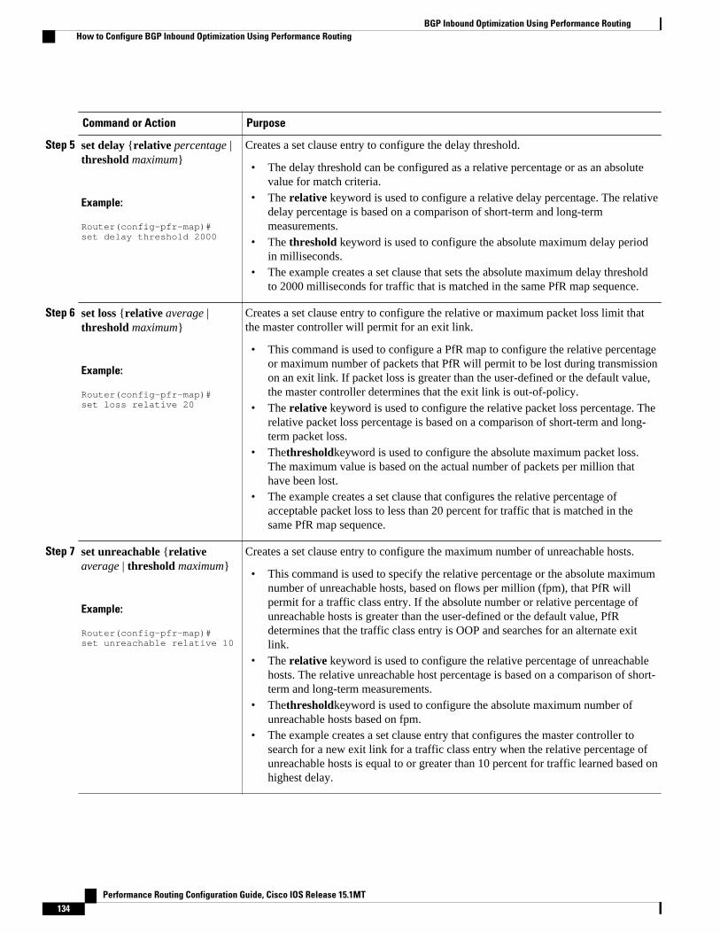
Command or Action Purpose
Step 5 set delay {relative percentage |threshold maximum}
Example:
Router(config-pfr-map)# set delay threshold 2000
Creates a set clause entry to configure the delay threshold.
• The delay threshold can be configured as a relative percentage or as an absolutevalue for match criteria.
• The relative keyword is used to configure a relative delay percentage. The relativedelay percentage is based on a comparison of short-term and long-termmeasurements.
• The threshold keyword is used to configure the absolute maximum delay periodin milliseconds.
• The example creates a set clause that sets the absolute maximum delay thresholdto 2000 milliseconds for traffic that is matched in the same PfR map sequence.
Step 6 set loss {relative average |threshold maximum}
Example:
Router(config-pfr-map)# set loss relative 20
Creates a set clause entry to configure the relative or maximum packet loss limit thatthe master controller will permit for an exit link.
• This command is used to configure a PfR map to configure the relative percentageor maximum number of packets that PfR will permit to be lost during transmissionon an exit link. If packet loss is greater than the user-defined or the default value,the master controller determines that the exit link is out-of-policy.
• The relative keyword is used to configure the relative packet loss percentage. Therelative packet loss percentage is based on a comparison of short-term and long-term packet loss.
• Thethresholdkeyword is used to configure the absolute maximum packet loss.The maximum value is based on the actual number of packets per million thathave been lost.
• The example creates a set clause that configures the relative percentage ofacceptable packet loss to less than 20 percent for traffic that is matched in thesame PfR map sequence.
Step 7 set unreachable {relativeaverage | threshold maximum}
Example:
Router(config-pfr-map)# set unreachable relative 10
Creates a set clause entry to configure the maximum number of unreachable hosts.
• This command is used to specify the relative percentage or the absolute maximumnumber of unreachable hosts, based on flows per million (fpm), that PfR willpermit for a traffic class entry. If the absolute number or relative percentage ofunreachable hosts is greater than the user-defined or the default value, PfRdetermines that the traffic class entry is OOP and searches for an alternate exitlink.
• The relative keyword is used to configure the relative percentage of unreachablehosts. The relative unreachable host percentage is based on a comparison of short-term and long-term measurements.
• Thethresholdkeyword is used to configure the absolute maximum number ofunreachable hosts based on fpm.
• The example creates a set clause entry that configures the master controller tosearch for a new exit link for a traffic class entry when the relative percentage ofunreachable hosts is equal to or greater than 10 percent for traffic learned based onhighest delay.
BGP Inbound Optimization Using Performance Routing How to Configure BGP Inbound Optimization Using Performance Routing
Performance Routing Configuration Guide, Cisco IOS Release 15.1MT134

Command or Action Purpose
Step 8 end
Example:
Router(config-pfr-map)# end
(Optional) Exits PfR map configuration mode and returns to privileged EXEC mode.
Configuring and Applying a PfR Policy to Configured Inside PrefixesPerform this task to apply a policy to configured inside prefix traffic class entries from the MTC list at themaster controller. Support for optimizing inside prefixes was introduced in the BGP Inbound Optimizationfeature. The policies are configured using a PfR map. This task contains prefix list configuration withdifferent criteria in the set clauses.
Note Policies applied in a PfR map do not override global policy configurations.
SUMMARY STEPS
1. enable
2. configure terminal
3. pfr-map map-name sequence-number
4. match ip address {access-list access-list-name| prefix-list prefix-list-name [inside]
5. set delay {relative percentage | threshold maximum}
6. set loss {relative average | threshold maximum}
7. set unreachable {relative average | threshold maximum}
8. end
DETAILED STEPS
Command or Action Purpose
Step 1 enable
Example:
Router> enable
Enables privileged EXEC mode.
• Enter your password if prompted.
Step 2 configure terminal
Example:
Router# configure terminal
Enters global configuration mode.
Configuring and Applying a PfR Policy to Configured Inside PrefixesHow to Configure BGP Inbound Optimization Using Performance Routing
Performance Routing Configuration Guide, Cisco IOS Release 15.1MT 135

Command or Action Purpose
Step 3 pfr-map map-name sequence-number
Example:
Router(config)# pfr-map INSIDE_CONFIGURE 10
Enters PfR map configuration mode to create or configure a PfR map.
• PfR map operation is similar to that of route maps.• Only a single match clause can be configured for each PfR map sequence.• Permit and deny sequences should be applied to lowest pfr-map sequence for
best performance.• The example creates an PfR map named INSIDE_CONFIGURE.
Step 4 match ip address {access-listaccess-list-name| prefix-listprefix-list-name [inside]
Example:
Router(config-pfr-map)# match ip address prefix-list INSIDE_PREFIXES inside
References an extended IP access list or IP prefix list as match criteria in a PfR map.
• Use theinside keyword to specify inside prefixes to support PfR BGP inboundoptimization that supports best entrance selection for traffic that originates fromprefixes outside an autonomous system destined for prefixes inside theautonomous system.
• The example creates a match clause entry using the prefix listINSIDE_PREFIXES that specifies inside prefixes.
Step 5 set delay {relative percentage |threshold maximum}
Example:
Router(config-pfr-map)# set delay threshold 2000
Creates a set clause entry to configure the delay threshold.
• The delay threshold can be configured as a relative percentage or as an absolutevalue for match criteria.
• The relative keyword is used to configure a relative delay percentage. Therelative delay percentage is based on a comparison of short-term and long-termmeasurements.
• The threshold keyword is used to configure the absolute maximum delay periodin milliseconds.
• The example creates a set clause that sets the absolute maximum delay thresholdto 2000 milliseconds for traffic that is matched in the same PfR map sequence.
Step 6 set loss {relative average |threshold maximum}
Example:
Router(config-pfr-map)# set loss relative 20
Creates a set clause entry to configure the relative or maximum packet loss limit thatthe master controller will permit for an exit link.
• This command is used to configure a PfR map to configure the relativepercentage or maximum number of packets that PfR will permit to be lost duringtransmission on an exit link. If packet loss is greater than the user-defined or thedefault value, the master controller determines that the exit link is out-of-policy.
• The relative keyword is used to configure the relative packet loss percentage.The relative packet loss percentage is based on a comparison of short-term andlong-term packet loss.
• Thethresholdkeyword is used to configure the absolute maximum packet loss.The maximum value is based on the actual number of packets per million thathave been lost.
• The example creates a set clause that configures the relative percentage ofacceptable packet loss to less than 20 percent for traffic that is matched in thesame PfR map sequence.
BGP Inbound Optimization Using Performance Routing How to Configure BGP Inbound Optimization Using Performance Routing
Performance Routing Configuration Guide, Cisco IOS Release 15.1MT136

Command or Action Purpose
Step 7 set unreachable {relativeaverage | threshold maximum}
Example:
Router(config-pfr-map)# set unreachable relative 10
Creates a set clause entry to configure the maximum number of unreachable hosts.
• This command is used to specify the relative percentage or the absolutemaximum number of unreachable hosts, based on flows per million (fpm), thatPfR will permit for a traffic class entry. If the absolute number or relativepercentage of unreachable hosts is greater than the user-defined or the defaultvalue, PfR determines that the traffic class entry is OOP and searches for analternate exit link.
• The relative keyword is used to configure the relative percentage of unreachablehosts. The relative unreachable host percentage is based on a comparison ofshort-term and long-term measurements.
• Thethresholdkeyword is used to configure the absolute maximum number ofunreachable hosts based on fpm.
• The example creates a set clause entry that configures the master controller tosearch for a new exit link for a traffic class entry when the relative percentage ofunreachable hosts is equal to or greater than 10 percent for traffic learned basedon highest delay.
Step 8 end
Example:
Router(config-pfr-map)# end
Exits PfR map configuration mode and returns to privileged EXEC mode.
Configuration Examples for BGP Inbound Optimization UsingPerformance Routing
• Example Configuring PfR to Automatically Learn Traffic Classes Using Inside Prefixes, page 137• Example Manually Selecting Inside Prefixes for PfR Monitoring, page 138• Example Modifying the PfR Link Utilization for Inbound Traffic, page 138• Example Modifying the PfR Entrance Link Utilization Range, page 138• Example Configuring and Applying a PfR Policy to Learned Inside Prefixes, page 138• Example Configuring and Applying a PfR Policy to Configured Inside Prefixes, page 139
Example Configuring PfR to Automatically Learn Traffic Classes UsingInside Prefixes
The following example shows how to configure PfR to automatically learn prefixes inside the network:
Router> enableRouter# configure terminalRouter(config)# pfr masterRouter(config-pfr-mc)# learn
Example Configuring PfR to Automatically Learn Traffic Classes Using Inside PrefixesConfiguration Examples for BGP Inbound Optimization Using Performance Routing
Performance Routing Configuration Guide, Cisco IOS Release 15.1MT 137

Router(config-pfr-mc-learn)# inside bgpRouter(config-pfr-mc-learn)# monitor-period 10 Router(config-pfr-mc-learn)# periodic-interval 20 Router(config-pfr-mc-learn)# prefixes 30Router(config-pfr-mc-learn)# end
Example Manually Selecting Inside Prefixes for PfR MonitoringThe following example shows how to manually configure PfR to learn prefixes inside the network using aPfR map:
Router> enableRouter# configure terminalRouter(config)# ip prefix-list INSIDE_PREFIXES seq 20 permit 192.168.1.0/24Router(config)# pfr-map INSIDE_MAP 10Router(config-pfr-map)# match ip address prefix-list INSIDE_PREFIXES insideRouter(config-pfr-map)# end
Example Modifying the PfR Link Utilization for Inbound TrafficThe following example shows how to modify the PfR entrance link utilization threshold. In this example,the entrance utilization is set to 65 percent. If the utilization for this exit link exceeds 65 percent, PfRselects another entrance link for traffic classes that were using this entrance link.
Router(config)# pfr master Router(config-pfr-mc)# border 10.1.2.1Router(config-pfr-mc-br)# interface GigabitEthernet 0/0/0 externalRouter(config-pfr-mc-br-if)# maximum receive utilization percentage 65Router(config-pfr-mc-br-if)# end
Example Modifying the PfR Entrance Link Utilization RangeThe following example shows how to modify the PfR entrance utilization range. In this example, theentrance utilization range for all entrance links is set to 15 percent.PfR uses the maximum utilization rangeto determine if entrance links are in-policy. PfR will equalize inbound traffic across all entrance links bymoving prefixes from overutilized or out-of-policy exits to in-policy exits.
Router(config)# pfr master Router(config-pfr-mc)# max range receive percent 15Router(config-pfr-mc)# end
Example Configuring and Applying a PfR Policy to Learned Inside PrefixesThe following example shows how to apply a PfR policy to learned inside prefixes:
enableconfigure terminalpfr-map INSIDE_LEARN 10 match pfr learn inside set delay threshold 2000 set loss relative 20 set unreachable relative 90 end
Example Manually Selecting Inside Prefixes for PfR Monitoring Configuration Examples for BGP Inbound Optimization Using Performance Routing
Performance Routing Configuration Guide, Cisco IOS Release 15.1MT138

Example Configuring and Applying a PfR Policy to Configured InsidePrefixes
The following example shows how to create a PfR map named INSIDE_CONFIGURE and apply a PfRpolicy to manually configured inside prefixes:
enableconfigure terminal pfr-map INSIDE_CONFIGURE 10 match ip address prefix-list INSIDE_PREFIXES inside set delay threshold 2000 set loss relative 20 set unreachable relative 80 end
Additional ReferencesRelated Documents
Related Topic Document Title
Cisco IOS commands Cisco IOS Master Commands List, All Releases
Cisco PfR commands: complete command syntax,command mode, command history, defaults, usageguidelines and examples
Cisco IOS Performance Routing CommandReference
Basic PfR configuration "Configuring Basic Performance Routing" module
Concepts required to understand the PerformanceRouting operational phases
"Understanding Performance Routing" module
Advanced PfR configuration "Configuring Advanced Performance Routing"module
IP SLAs overview IP SLAs Configuration Guide
Technical Assistance
Description Link
The Cisco Support and Documentation websiteprovides online resources to downloaddocumentation, software, and tools. Use theseresources to install and configure the software andto troubleshoot and resolve technical issues withCisco products and technologies. Access to mosttools on the Cisco Support and Documentationwebsite requires a Cisco.com user ID andpassword.
http://www.cisco.com/cisco/web/support/index.html
Example Configuring and Applying a PfR Policy to Configured Inside PrefixesAdditional References
Performance Routing Configuration Guide, Cisco IOS Release 15.1MT 139

Feature Information for BGP Inbound Optimization UsingPerformance Routing
The following table provides release information about the feature or features described in this module.This table lists only the software release that introduced support for a given feature in a given softwarerelease train. Unless noted otherwise, subsequent releases of that software release train also support thatfeature.
Use Cisco Feature Navigator to find information about platform support and Cisco software image support.To access Cisco Feature Navigator, go to www.cisco.com/go/cfn. An account on Cisco.com is not required.
Table 5 Feature Information for BGP Inbound Optimization Using Performance Routing
Feature Name Releases Feature Information
OER BGP Inbound Optimization 12.4(9)T 12.2(33)SRB PfR BGP inbound optimizationsupports best entrance selectionfor traffic that originates fromprefixes outside an autonomoussystem destined for prefixesinside the autonomous system.External BGP (eBGP)advertisements from anautonomous system to an Internetservice provider (ISP) caninfluence the entrance path fortraffic entering the network. PfRuses eBGP advertisements tomanipulate the best entranceselection.
The following commands wereintroduced or modified by thisfeature: clear pfr master prefix,downgrade bgp (PfR), insidebgp (PfR), match ip address(PfR), match pfr learn, maxrange receive (PfR), maximumutilization receive (PfR), showpfr master prefix.
BGP Inbound Optimization Using Performance Routing Feature Information for BGP Inbound Optimization Using Performance Routing
Performance Routing Configuration Guide, Cisco IOS Release 15.1MT140

Feature Name Releases Feature Information
expire after command5 12.3(14)T 12.2(33)SRB Theexpire after (PfR)commandis used to set an expiration periodfor learned prefixes. By default,the master controller removesinactive prefixes from the centralpolicy database as memory isneeded. This command allowsyou to refine this behavior bysetting a time or session basedlimit. The time based limit isconfigured in minutes. Thesession based limit is configuredfor the number of monitor periods(or sessions).
Cisco and the Cisco Logo are trademarks of Cisco Systems, Inc. and/or its affiliates in the U.S. and othercountries. A listing of Cisco's trademarks can be found at www.cisco.com/go/trademarks. Third partytrademarks mentioned are the property of their respective owners. The use of the word partner does notimply a partnership relationship between Cisco and any other company. (1005R)
Any Internet Protocol (IP) addresses and phone numbers used in this document are not intended to beactual addresses and phone numbers. Any examples, command display output, network topology diagrams,and other figures included in the document are shown for illustrative purposes only. Any use of actual IPaddresses or phone numbers in illustrative content is unintentional and coincidental.
5 This is a minor enhancement. Minor enhancements are not typically listed in Feature Navigator.
BGP Inbound Optimization Using Performance Routing
Performance Routing Configuration Guide, Cisco IOS Release 15.1MT 141

Example Configuring and Applying a PfR Policy to Configured Inside Prefixes
Performance Routing Configuration Guide, Cisco IOS Release 15.1MT142

Configuring Performance Routing Cost Policies
This module describes how to configure and apply Cisco IOS Performance Routing (PfR) cost policies. APfR policy can be configured to optimize traffic based on the monetary cost of the exit links. The PfRCost Based Optimization feature provides financial benefits by directing traffic to lower cost links, whileat the same time honoring other configured policies such as delay, loss, and utilization. Cost BasedOptimization can be applied to links that are billed using a fixed or tiered billing method. Load balancingbased on cost can also be achieved.
• Finding Feature Information, page 143• Prerequisites for Performance Routing Cost Policies, page 143• Information About Performance Routing Cost Policies, page 143• How to Configure Performance Routing Cost Policies, page 148• Configuration Examples for Performance Routing Cost Policies, page 163• Where to Go Next, page 166• Additional References, page 166• Feature Information for Configuring Performance Routing Cost Policies, page 167
Finding Feature InformationYour software release may not support all the features documented in this module. For the latest featureinformation and caveats, see the release notes for your platform and software release. To find informationabout the features documented in this module, and to see a list of the releases in which each feature issupported, see the Feature Information Table at the end of this document.
Use Cisco Feature Navigator to find information about platform support and Cisco software image support.To access Cisco Feature Navigator, go to www.cisco.com/go/cfn. An account on Cisco.com is not required.
Prerequisites for Performance Routing Cost PoliciesBefore implementing PfR cost policies, you need to understand an overview of how PfR works and how toset up PfR network components. See the “Understanding Performance Routing,” “Configuring BasicPerformance Routing,” and “Configuring Advanced Performance Routing,” modules for more details.
Information About Performance Routing Cost PoliciesTo configure and apply PfR policies, you should understand the following concepts:
• Overview of PfR Link Policies, page 144
Performance Routing Configuration Guide, Cisco IOS Release 15.1MT 143

• Traffic Load (Utilization) Policy, page 144• Range Policy, page 144• Cost Policy, page 145
Overview of PfR Link PoliciesPfR link policies are a set of rules that are applied against PfR-managed external links (an external link isan interface on a border router on the network edge). Link policies define the desired performancecharacteristics of the links. Instead of defining the performance of an individual traffic class entry that usesthe link (as in traffic class performance policies), link policies are concerned with the performance of thelink as a whole. Link policies are applied both to exit (egress) links and entrance (ingress) links. Thefollowing link policy types describe the different performance characteristics that can be managed usinglink policies:
Traffic Load (Utilization) PolicyA traffic load (also referred to as utilization) policy consists of an upper threshold on the amount of trafficthat a specific link can carry. Cisco IOS PfR supports per traffic class load distribution. Every 20 seconds,by default, the border router reports the link utilization to the master controller, after an external interface isconfigured for a border router. Both exit link traffic and entrance link traffic load thresholds can beconfigured as a PfR policy. If the exit or entrance link utilization is above the configured threshold, or thedefault threshold of 75-percent, the exit or entrance link is in an out-of-policy (OOP) state and PfR startsthe monitoring process to find an alternative link for the traffic class. The link utilization threshold can bemanually configured either as an absolute value in kilobytes per second (kbps) or as a percentage. A loadutilization policy for an individual interface is configured on the master controller under the border routerconfiguration.
Tip When configuring load distribution, we recommend that you set the interface load calculation on externalinterfaces to 30-second intervals with the load-interval interface configuration command. The defaultcalculation interval is 300 seconds. The load calculation is configured under interface configuration modeon the border router. This configuration is not required, but it is recommended to allow Cisco IOS PfR torespond as quickly as possible to load distribution issues.
A traffic load policy describes an upper limit for the traffic to be carried on a single link. For more detailsabout configuring a traffic load policy, see the Configuring an Exit Link Load Balancing PfR Policy:Example configuration example in the "Configuring Advanced Performance Routing" module.
Range PolicyA range policy is defined to maintain all links within a certain utilization range, relative to each other inorder to ensure that the traffic load is distributed. For example, if a network has multiple exit links, andthere is no financial reason to choose one link over another, the optimal choice is to provide an even loaddistribution across all links. The load-sharing provided by traditional routing protocols is not always evenlydistributed, because the load-sharing is flow-based rather than performance- or policy-based. Cisco PfRrange functionality allows you to configure PfR to maintain the traffic utilization on a set of links within acertain percentage range of each other. If the difference between the links becomes too great, PfR willattempt to bring the link back to an in-policy state by distributing traffic classes among the available links.The master controller sets the maximum range utilization to 20 percent for all PfR-managed links bydefault, but the utilization range can be configured using a maximum percentage value.
Overview of PfR Link Policies Information About Performance Routing Cost Policies
Performance Routing Configuration Guide, Cisco IOS Release 15.1MT144

Both exit link and entrance link utilization ranges can be configured as a PfR policy.
Note When configuring a range policy remember that 80 percent utilization of a serial link is very different from80 percent utilization of a GigabitEthernet link.
A range policy describes a method of load-balancing the traffic over multiple links. For more details aboutconfiguring a range policy, see the Configuring an Exit Link Load Balancing PfR Policy: Exampleconfiguration example in the Configuring Advanced Performance Routing module.
Cost PolicyPfR support for cost-based optimization was introduced in Cisco IOS Release 12.3(14)T, 12.2(33)SRB, andlater releases. Cost-based optimization allows you to configure policies based on the monetary cost (ISPservice level agreements [SLAs]) of each exit link in your network. To implement PfR cost-basedoptimization the PfR master controller is configured to send traffic over exit links that provide the mostcost-effective bandwidth utilization, while still maintaining the desired performance characteristics. A costpolicy describes a method of load-balancing the traffic over multiple links.
In response to changing business practices, in Cisco IOS Release 12.4(15)T9 and later releases, thecalculation of the Momentary Target Link Utilization (MTLU) algorithm is modified to allow for moreefficient bandwidth utilization while minimizing the link cost.
To understand how cost-based optimization works, review the following sections:
• Cost Policy Billing Models, page 145• Link Utilization Rollup Calculations, page 145• Monthly Sustained Utilization Calculation, page 146
Cost Policy Billing ModelsPfR cost-based optimization supports two methods of billing: fixed-rate billing or tier-based billing.
Fixed-rate billing is used when the ISP bills one flat rate for a link regardless of bandwidth usage. If fixed-rate billing only is configured on the exit links, all exits are considered equal with regard to cost-optimization and other policy parameters (such as delay, loss, and utilization) are used to determine if theprefix or exit link is in-policy.
Tier-based billing is used when the ISP bills at a tiered rate based on the percentage of exit link utilization.Each cost tier is configured separately with an associated monetary cost and a percentage of bandwidthutilization that activates the tier is defined. The lowest cost tier for an exit using tier-based billing ischarged each month regardless of the bandwidth actually utilized. An allowance is made for bursting in thealgorithm used to determine the tier-based billing. In this situation, bursting is defined as short periods ofhigh bandwidth usage that would be expensive under fixed-rate billing.
A fixed-rate billing is a set monthly fee regardless of utilization. Tier-based billing also incurs at least thelowest-tier cost per month, but the final monthly tier-based billing charge is determined by the costassigned to the tier that matches the sustained monthly utilization.
Link Utilization Rollup CalculationsThe first step in determining the billing fee for each exit link per month is to calculate the link utilizationrollup values. Link utilization rollup values are the averages of the link utilization readings taken at regularintervals (sampling period) from the ingress and egress interfaces at the border routers for a given rollup
Cost PolicyCost Policy Billing Models
Performance Routing Configuration Guide, Cisco IOS Release 15.1MT 145

period. For example, if a sampling period was set to 60 minutes, and the rollup was set at 1440 minutes (24hours), we would have 24 ingress and 24 egress link utilization samples used for calculating the linkutilization rollup. An average is taken for each set of ingress and egress samples from that rollup period toget a link utilization rollup value for the ingress and egress links.
Monthly Sustained Utilization CalculationAfter the link utilization rollup calculation is performed, the monthly sustained utilization is calculated, Thespecific details of tier-based billing models vary by ISP. However, most ISPs use some variation of thefollowing algorithm to calculate what an enterprise should pay in a tiered billing plan:
• Gather periodic measurements of egress and ingress traffic carried on the enterprise connection to theISP network and aggregate the measurements to generate a rollup value for a rollup period.
• Calculate one or more rollup values per billing period.• Rank the rollup values for the billing period into a stack from the largest value to the smallest.• Discard the top default 5 percent (an absolute or percentage value can be configured, but 5 percent is
the default) of the rollup values from the stack to accommodate bursting. In this situation, bursting isdefined as any bandwidth above the sustained monthly utilization. The remaining rollup values areknown as the 95th percentile high if the default 5% is discarded.
• After the rollups with the highest utilization values (the top 5 percent in this case) are removed, applythe highest remaining rollup value in the stack, referred to as the sustained Monthly Target LinkUtilization (MTLU), to a tiered structure to determine a tier associated with the rollup value.
• Charge the customer based on a set cost associated with the identified tier.
Note A billing policy must be configured and applied to links in order for the master controller to perform cost-based optimization.
The monthly sustained utilization rollup calculations can be configured to use one of the following threetechniques:
• Combined• Separate• Summed
In the following explanations of the sustained utilization calculation techniques, the discard value isconfigured as an absolute value of 10. The default discard value is 5 percent.
Using the combined technique, the monthly sustained utilization calculation is based on a combination ofthe egress and ingress rollup samples on a single sorted stack, the highest 10 rollup values are discarded,and the next highest rollup value is the MTLU.
Using the separate technique, the egress and ingress rollup samples for a link are sorted into separate stacksand the highest 10 rollup values for each stack are discarded. The highest remaining rollup value of the twostacks is selected as the MTLU.
Using the summed technique the egress and ingress rollup samples are added together. The summed valuesof each rollup sample are placed into one stack, the top 10 rollup values are discarded, leaving the nexthighest rollup value as the MTLU.
The following table displays an example of how the sustained monthly utilization is calculated using theseparate technique. In the table below the rollup values for a 30-day period are displayed in order from thehighest bandwidth to the lowest bandwidth for both the egress and ingress rollup values. The top 10 values(shown in italic) are discarded because the master controller has been configured to discard this absolute
Configuring Performance Routing Cost Policies Monthly Sustained Utilization Calculation
Performance Routing Configuration Guide, Cisco IOS Release 15.1MT146

number of rollups. The next highest rollup value remaining in the two stacks, 62 (shown in bold), is thesustained monthly utilization. The sustained monthly utilization is used to determine the tier at which thecustomer is billed for bandwidth usage on that link for that billing period.
Table 6 Sustained Monthly Utilization Example Calculation
Egress Rollups Ingress Rollups Rollups are Sorted from HighestBandwidth to Lowest Bandwidthin Billing Period
89 92 Discard the top 10 egress andingress as configured as anabsolute value (see numbers initalics).
80 84
71 82
70 80
65 78
65 75
51 73
50 84
49 82
49 80
45 62 After the discarded values. thenext highest value is 62 and thisbecomes the Sustained MonthlyUtilization
42 60
39 55
35 53
34 52
30 45
30 43
30 35
29 33
25 31
Configuring Performance Routing Cost PoliciesMonthly Sustained Utilization Calculation
Performance Routing Configuration Guide, Cisco IOS Release 15.1MT 147
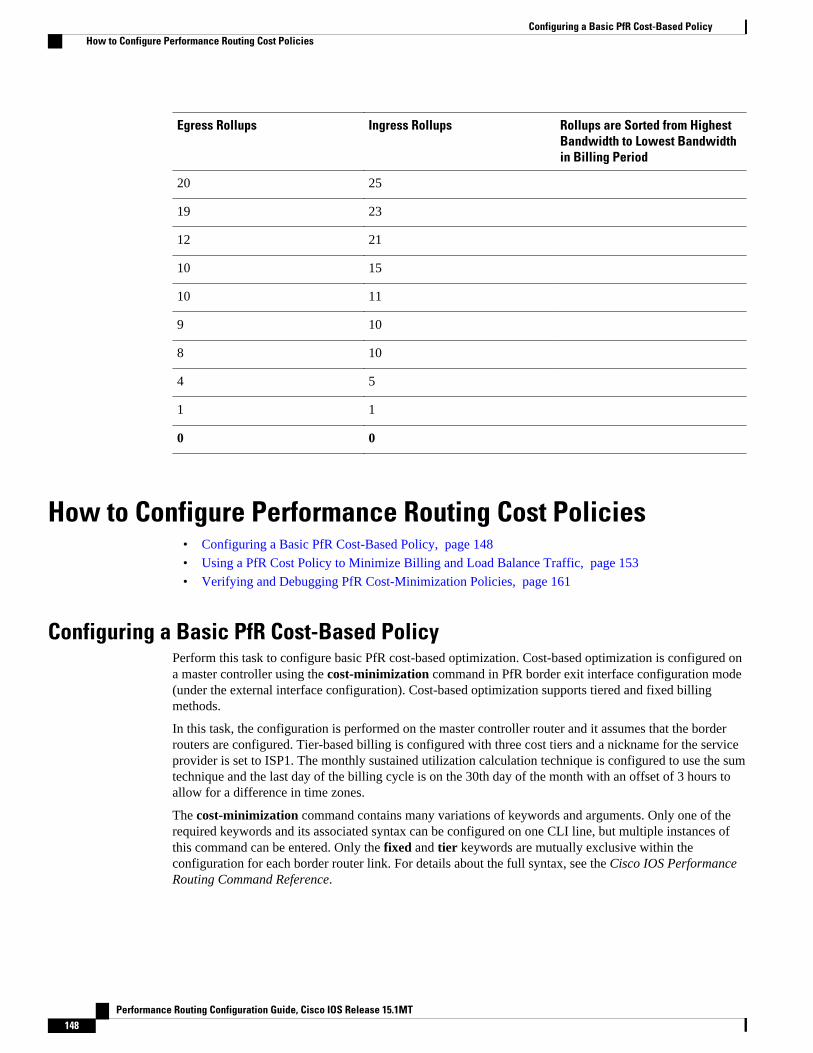
Egress Rollups Ingress Rollups Rollups are Sorted from HighestBandwidth to Lowest Bandwidthin Billing Period
20 25
19 23
12 21
10 15
10 11
9 10
8 10
4 5
1 1
0 0
How to Configure Performance Routing Cost Policies• Configuring a Basic PfR Cost-Based Policy, page 148
• Using a PfR Cost Policy to Minimize Billing and Load Balance Traffic, page 153
• Verifying and Debugging PfR Cost-Minimization Policies, page 161
Configuring a Basic PfR Cost-Based PolicyPerform this task to configure basic PfR cost-based optimization. Cost-based optimization is configured ona master controller using the cost-minimization command in PfR border exit interface configuration mode(under the external interface configuration). Cost-based optimization supports tiered and fixed billingmethods.
In this task, the configuration is performed on the master controller router and it assumes that the borderrouters are configured. Tier-based billing is configured with three cost tiers and a nickname for the serviceprovider is set to ISP1. The monthly sustained utilization calculation technique is configured to use the sumtechnique and the last day of the billing cycle is on the 30th day of the month with an offset of 3 hours toallow for a difference in time zones.
The cost-minimization command contains many variations of keywords and arguments. Only one of therequired keywords and its associated syntax can be configured on one CLI line, but multiple instances ofthis command can be entered. Only the fixed and tier keywords are mutually exclusive within theconfiguration for each border router link. For details about the full syntax, see the Cisco IOS PerformanceRouting Command Reference.
Configuring a Basic PfR Cost-Based Policy How to Configure Performance Routing Cost Policies
Performance Routing Configuration Guide, Cisco IOS Release 15.1MT148

SUMMARY STEPS
1. enable
2. configure terminal
3. pfr master
4. border ip-address [key-chain key-chain-name]
5. interface type number external
6. cost-minimization nickname name
7. cost-minimization calc {combined | separate | sum}
8. cost-minimization sampling period minutes [rollup minutes]
9. cost-minimization end day-of-month day [offset [-] hh:mm]
10. cost-minimization {fixed fee cost| tier percentage fee fee}
11. Repeat Step 9 to configure additional tiers for a tier-based billing cycle.
12. exit
13. interface type number internal
14. exit
15. Repeat Step 14 to return to PfR master controller configuration mode.
16. Repeat from Step 4 to Step 15 to configure additional cost-based optimization policies for other links, ifrequired.
17. mode route control
18. resolve cost priority value
19. end
DETAILED STEPS
Command or Action Purpose
Step 1 enable
Example:
Router> enable
Enables privileged EXEC mode.
• Enter your password if prompted.
Step 2 configure terminal
Example:
Router# configure terminal
Enters global configuration mode.
Step 3 pfr master
Example:
Router(config)# pfr master
Enters PfR master controller configuration mode to configure global prefixand exit link policies.
Configuring Performance Routing Cost PoliciesHow to Configure Performance Routing Cost Policies
Performance Routing Configuration Guide, Cisco IOS Release 15.1MT 149

Command or Action Purpose
Step 4 border ip-address [key-chain key-chain-name]
Example:
Router(config-pfr-mc)# border 10.100.1.1 key-chain PFR_cost
Enters PfR-managed border router configuration mode to establishcommunication with a border router.
• An IP address is configured to identify the border router.• The value for the key-chain-name argument must match the key-chain
name configured at the border router identified by the ip-addressargument.
Note The key-chain keyword and key-chain-name argument must be enteredwhen a border router is initially configured. However, this keyword isoptional when reconfiguring or adding configuration for this borderrouter.
Step 5 interface type number external
Example:
Router(config-pfr-mc-br)# interface ethernet 0/0 external
Enters PfR border exit interface configuration mode to configure a borderrouter interface as an external interface.
• At least one external interface must be configured on each border router.
Step 6 cost-minimization nickname name
Example:
Router(config-pfr-mc-br-if)# cost-minimization nickname ISP1
Configures a nickname for a border router interface within a cost-basedoptimization policy on a master controller.
• Use the nickname keyword to apply a label that identifies the serviceprovider.
• In this example, the label of ISP1 is configured for the service provider.
Step 7 cost-minimization calc {combined |separate | sum}
Example:
Router(config-pfr-mc-br-if)# cost-minimization calc sum
Configures how the cost-minimization fee is calculated.
• Use the combined keyword to configure the master controller to combineingress and egress samples.
• Use the separate keyword to configure the master controller to analyzeingress and egress samples separately.
• Use the sum keyword to configure the master controller to first addingress and egress samples and then combine the samples.
• In this example, cost-minimization fee is calculated using the sumtechnique.
Step 8 cost-minimization sampling periodminutes [rollup minutes]
Example:
Router(config-pfr-mc-br-if)# cost-minimization sampling period 10 rollup 60
Specifies the sampling period in minutes.
• The value that can be entered for the sampling period minutes argumentis a number from 1 to 1440.
• Use the optional rollupkeyword to specify that samples are rolled up atthe interval specified for the minutes argument. The value that can beentered for the rollup minutes argument is a number from 1 to 1440. Theminimum number that can be entered must be equal to or greater than thenumber that is entered for the sampling period.
• In this example, the time interval between sampling is set to 10 minutes.These samples are configured to be rolled up every 60 minutes.
Configuring Performance Routing Cost Policies How to Configure Performance Routing Cost Policies
Performance Routing Configuration Guide, Cisco IOS Release 15.1MT150

Command or Action Purpose
Step 9 cost-minimization end day-of-monthday [offset [-] hh:mm]
Example:
Router(config-pfr-mc-br-if)# cost-minimization end day-of-month 30 offset 5:00
Configures the parameters used to configure the last day of the billing cycle.
• Use the optional offsetkeyword to adjust the end of the cycle tocompensate for a service provider in a different zone from UTC. Theoptional “-” keyword is used to allow for negative hours and minutes tobe specified when the time zone is ahead of UTC.
• In this example, the last day of the billing cycle is on the 30th day of themonth with an offset of 5 hours added to UTC.
Step 10 cost-minimization {fixed fee cost| tierpercentage fee fee}
Example:
Router(config-pfr-mc-br-if)# cost-minimization tier 100 fee 1000
Configures a nonusage-based fixed cost billing cycle or a tier of a tier-basedbilling cycle.
• The fixed fee keywords and cost argument are used to specify a fixed(nonusage-based) cost associated with an exit link.
• The percentage argument is used to specify the percentage of capacityutilization for a cost tier.
• The tier fee keywords and fee argument are used to specify the feeassociated with this tier.
• In this example, the tier-based fee for 100 percent utilization is set to1000.
Note The first tier specified must be the 100 percent capacity utilization. Anyfollowing tier configurations must be for lesser percentages and lowerfees.
Step 11 Repeat Step 9 to configure additionaltiers for a tier-based billing cycle.
--
Step 12 exit
Example:
Router(config-pfr-mc-br-if)# exit
Exits PfR border exit interface configuration mode and returns to PfR-managed border router configuration mode.
Step 13 interface type number internal
Example:
Router(config-pfr-mc-br)# interface Ethernet 1/0 internal
Configures a border router interface as a PfR controlled internal interface.
• Internal interfaces are used for passive monitoring only. Internalinterfaces do not forward traffic.
• At least one internal interface must be configured on each border router.
Note Support to configure a VLAN interface as an internal interface wasintroduced in Cisco IOS Release 12.3(14)T, and 12.2(33)SRB.
Step 14 exit
Example:
Router(config-pfr-mc-br-if)# exit
Exits PfR border exit interface configuration mode and returns to PfR-managed border router configuration mode.
Configuring Performance Routing Cost PoliciesHow to Configure Performance Routing Cost Policies
Performance Routing Configuration Guide, Cisco IOS Release 15.1MT 151

Command or Action Purpose
Step 15 Repeat Step 14 to return to PfR mastercontroller configuration mode.
--
Step 16 Repeat from Step 4 to Step 15 toconfigure additional cost-basedoptimization policies for other links, ifrequired.
--
Step 17 mode route control
Example:
Router(config-pfr-mc)# mode route control
Configures route control for matched traffic.
• In control mode, the master controller analyzes monitored prefixes andimplements changes based on policy parameters.
Step 18 resolve cost priority value
Example:
Router(config-pfr-mc)# resolve cost priority 1
Sets policy priority for cost policies.
• The resolve policy configures cost policies to have the highest priority.• In this task, only one type of PfR policy is given priority. Be aware that
other PfR policies are usually configured and priorities must be carefullyreviewed.
Step 19 end
Example:
Router(config-pfr-mc)# end
Exits PfR master controller configuration mode and returns to privilegedEXEC mode.
Example:
The following example is just a sample configuration as shown in the task but with the added tiers tocomplete the tier-based fee configuration. For a more complete example configuration of a basic PfR costpolicy that includes both fixed-rate and tier-based billing, see the "Example: Configuring a Basic PfR Cost-Based Policy" section.
pfr master border 10.100.1.1 key-chain PFR_cost interface Ethernet 0/0 external cost-minimization nickname ISP1 cost-minimization calc sum cost-minimization sampling period 10 rollup 60 cost-minimization end day-of-month 30 offset 5:00 cost-minimization tier 100 fee 1000 cost-minimization tier 70 fee 700 cost-minimization tier 50 fee 500 exit interface Ethernet 1/0 internal exit mode route control resolve cost priority 1 end
Configuring Performance Routing Cost Policies How to Configure Performance Routing Cost Policies
Performance Routing Configuration Guide, Cisco IOS Release 15.1MT152

Using a PfR Cost Policy to Minimize Billing and Load Balance TrafficWhile basic PfR cost-based optimization can be useful, many organizations have multiple border router exitlinks and possibly several different service providers charging different billing rates that increase accordingto the bandwidth utilized. In this situation, some form of traffic load balancing across the links may berequired in addition to the cost minimization policy.
Perform this task on the master controller to configure a Performance Routing cost policy to minimize themonthly billing charge for multiple border router exit links while load balancing traffic across the links. Inthis scenario, the network has both fixed-rate and tier-based billing, and assuming that the customer ispaying a monthly fee for the fixed-rate billing and the pre-paid (lowest cost) tier of tier-based billing, PfRcan perform traffic load balancing while optimizing for cost.
The figure below shows an example of how different billing rates can be defined for each link usingbandwidth and cost parameters that are defined through service level agreements (SLAs) that are identifiedas rules in the diagram. The main goal of this task is to minimize the billing charge per exit link and to loadbalance traffic across the exit links. Although Link 1 may be billed at a fixed-rate and Links 2 through 4 aresubject to tier-based billing, all the links are set up as PfR tiers. To accomplish the cost minimization thefirst rule is to utilize 80 percent of Link 1 and 30 percent of Links 2, 3 and 4, as shown in the figure below.The second rule is to distribute additional traffic across Links 2, 3 and 4 to balance the traffic load. Toachieve the traffic load balancing while minimizing cost, the solution is to configure a PfR cost policyusing multiple tiers representing bandwidth percentages that are assigned artificial costs to ensure that thePfR traffic is optimized for cost and load balanced across all the exits. To illustrate the configured tiers, seethe figure below.
The steps in this task create a cost policy in which PfR is configured to direct traffic through any of thelowest cost exits first; Link 1 at 10.1.1.1 and the pre-paid tier of the other three exits. When the pre-paidtier bandwidth at each link is fully utilized, the software determines the next lowest incremental costbetween the tiers at all the links. The incremental cost of utilizing the next tier at Link 1 is $990. Theincremental cost of utilizing the next tier at Link 2 is only $10. PfR forwards traffic to the next lowest costtier which is the blue bar representing 40 percent of the bandwidth at Link 2, as shown in the figure below.The process continues to use cost to balance the load across Links 2, 3, and 4. This task illustrates how themonthly billing rate per exit link is minimized by utilizing the pre-paid bandwidth at Links 1 though 4 first,
Using a PfR Cost Policy to Minimize Billing and Load Balance TrafficHow to Configure Performance Routing Cost Policies
Performance Routing Configuration Guide, Cisco IOS Release 15.1MT 153

and then the traffic is effectively load balanced across Links 2, 3 and 4 by determining the lowestincremental cost between tiers.
Figure 11 Diagram Showing PfR Cost-Minimization Solution to Minimize Billing and Load Balance Traffic
In the following task steps, the exit link 10.1.1.1 is configured as a tier-based link although it is actuallycharged at a fixed rate. If a fixed rate link is configured as a tier for load balancing, the monthly costcalculation will not reflect the true cost for that link. Using this solution, the artificial costs assigned to themultiple tiers may affect the accuracy of all the monthly cost calculations.
Only some of the configuration steps for this task scenario are shown in the summary and detailed steps,the full configuration for the master controller is displayed in the Examples section shown after the detailedsteps table.
Note Disable the range and utilization policy priorities because they may conflict with this application of thecost-minimization feature.
Note Do not configure the periodic(PfR) or the set periodic(PfR) command with a time interval to avoid systemchurn as the system tries to select the best exit link at specified intervals. This command is disabled bydefault.
The cost-minimization (PfR) command contains many variations of keywords and arguments. Only one ofthe required keywords and its associated syntax can be configured on one CLI line, but multiple instancesof this command can be entered. Only the fixed and tier keywords are mutually exclusive within theconfiguration for each border router link. For details about the full syntax, see the Cisco IOS PerformanceRouting Command Reference.
Configuring Performance Routing Cost Policies How to Configure Performance Routing Cost Policies
Performance Routing Configuration Guide, Cisco IOS Release 15.1MT154

SUMMARY STEPS
1. enable
2. configure terminal
3. pfr master
4. border ip-address [key-chain key-chain-name]
5. interface type number external
6. cost-minimization nickname name
7. cost-minimization summer-time start end [offset]
8. cost-minimization {fixed fee cost| tier percentage fee fee}
9. Repeat Step 8 to configure additional tiers for a tier-based billing cycle.
10. cost-minimization discard [daily] {absolute number| percent percentage}
11. exit
12. interface type number internal
13. exit
14. Repeat Step 13 to return to PfR master controller configuration mode.
15. Repeat from Step 4 to Step 14 to configure additional cost-based optimization policies for other links, ifrequired.
16. mode route control
17. policy-rules map-name
18. exit
19. pfr-map map-name sequence-number
20. match pfr learn {delay| inside| throughput}
21. set resolve cost priority value
22. end
DETAILED STEPS
Command or Action Purpose
Step 1 enable
Example:
Router> enable
Enables privileged EXEC mode.
• Enter your password if prompted.
Step 2 configure terminal
Example:
Router# configure terminal
Enters global configuration mode.
Configuring Performance Routing Cost PoliciesHow to Configure Performance Routing Cost Policies
Performance Routing Configuration Guide, Cisco IOS Release 15.1MT 155

Command or Action Purpose
Step 3 pfr master
Example:
Router(config)# pfr master
Enters PfR master controller configuration mode to configure global prefixand exit link policies.
Step 4 border ip-address [key-chain key-chain-name]
Example:
Router(config-pfr-mc)# border 10.1.1.1 key-chain pfr
Enters PfR-managed border router configuration mode to establishcommunication with a border router.
• An IP address is configured to identify the border router.• The value for the key-chain-name argument must match the key-chain
name configured at the border router identified by the ip-addressargument.
Note The key-chain keyword and key-chain-name argument must be enteredwhen a border router is initially configured. However, this keyword isoptional when reconfiguring or adding configuration for this borderrouter.
Step 5 interface type number external
Example:
Router(config-pfr-mc-br)# interface ethernet 0/0 external
Enters PfR border exit interface configuration mode to configure a borderrouter interface as a PfR-managed external interface.
• At least one external interface must be configured on each border router.• Configuring an interface as a PfR-managed external interface on a router
enters PfR border exit interface configuration mode. In this mode, youcan configure maximum link utilization or cost-based optimization forthe interface.
Step 6 cost-minimization nickname name
Example:
Router(config-pfr-mc-br-if)# cost-minimization nickname 80-percent
Configures a nickname for a border router interface within a cost-basedoptimization policy on a master controller.
• In this example, the nickname label for the 10.1.1.1 border router link is80-percent.
Configuring Performance Routing Cost Policies How to Configure Performance Routing Cost Policies
Performance Routing Configuration Guide, Cisco IOS Release 15.1MT156

Command or Action Purpose
Step 7 cost-minimization summer-time startend [offset]
Example:
Router(config-pfr-mc-br-if)# cost-minimization summer-time 2 Sunday March 02:00 1 Sunday November 02:00 60
Specifies the start and end dates and times for summer time (daylightsavings).
• The start and end arguments are used to specify the week number, day,month and time in hours and minutes (24 hour clock) that summertimestarts and ends.
• The offset argument allows for an offset in minutes from 1 to 120 toallow for up to two additional hours to be added in the spring andsubtracted in the fall.
• In this example, summer time is configured to start the second week inMarch on a Sunday at 2 in the morning plus one hour, and end on Sundayin the first week in November at 2 in the morning minus one hour.
Note The summer-time keyword configuration is only required once foreach master controller.
Step 8 cost-minimization {fixed fee cost| tierpercentage fee fee}
Example:
Router(config-pfr-mc-br-if)# cost-minimization tier 100 fee 1000
Configures a nonusage-based fixed cost billing cycle or a tier of a tier-basedbilling cycle.
• The fixed fee keywords and cost argument are used to specify a fixed(nonusage-based) cost associated with an exit link.
• The percentage argument is used to specify the percentage of capacityutilization for a cost tier.
• The tier fee keywords and fee argument are used to specify the feeassociated with this tier.
• In this example, the tier-based fee for 100 percent utilization is set to1000.
Note The first tier specified must be the 100 percent capacity utilization. Anyfollowing tier configurations must be for lesser percentages and lowerfees. When setting up tiers for load balancing, the tiers must beincrementally larger from one tier to the next tier on the same link inorder for load balancing to work.
Step 9 Repeat Step 8 to configure additionaltiers for a tier-based billing cycle.
--
Configuring Performance Routing Cost PoliciesHow to Configure Performance Routing Cost Policies
Performance Routing Configuration Guide, Cisco IOS Release 15.1MT 157

Command or Action Purpose
Step 10 cost-minimization discard [daily]{absolute number| percent percentage}
Example:
Router(config-pfr-mc-br-if)# cost-minimization discard percent 5
Configures the number of samples that are removed for bursty link utilizationwhen calculating the sustained monthly utilization value.
• The utilization samples are ordered from the highest to the lowest and thenumber or percentage configured using this command removes thehighest number or percentage from the list.
• If the optional daily keyword is entered, samples are analyzed anddiscarded on a daily basis. If the daily keyword is not entered, by defaultthe samples are analyzed and discarded on a monthly basis. At the end ofthe billing cycle, monthly sustained usage is calculated by averagingdaily sustained utilization.
• Use the absolute keyword to configure a set number of samples to beremoved.
• Use the percentage keyword to configure a percentage number ofsamples to be removed.
• If a sampling rollup is configured, the discard values also applies to therollup.
• In this example, the highest 5 percent of samples are removed whencalculating the sustained monthly utilization value.
Step 11 exit
Example:
Router(config-pfr-mc-br-if)# exit
Exits PfR border exit interface configuration mode and returns to PfR-managed border router configuration mode.
Step 12 interface type number internal
Example:
Router(config-pfr-mc-br)# interface Ethernet 1/0 internal
Configures a border router interface as a PfR controlled internal interface.
• Internal interfaces are used for passive monitoring only. Internalinterfaces do not forward traffic.
• At least one internal interface must be configured on each border router.
Step 13 exit
Example:
Router(config-pfr-mc-br-if)# exit
Exits PfR border exit interface configuration mode and returns to PfR-managed border router configuration mode.
Step 14 Repeat Step 13 to return to PfR mastercontroller configuration mode.
--
Step 15 Repeat from Step 4 to Step 14 toconfigure additional cost-basedoptimization policies for other links, ifrequired.
--
Configuring Performance Routing Cost Policies How to Configure Performance Routing Cost Policies
Performance Routing Configuration Guide, Cisco IOS Release 15.1MT158

Command or Action Purpose
Step 16 mode route control
Example:
Router(config-pfr-mc)# mode route control
Configures route control for matched traffic.
• In control mode, the master controller analyzes monitored prefixes andimplements changes based on policy parameters.
Step 17 policy-rules map-name
Example:
Router(config-pfr-mc)# policy-rules cost_balance
Applies a configuration from a PfR map to a master controller configuration.
• In this example, configuration from a PfR map named cost_balance isapplied.
Step 18 exit
Example:
Router(config-pfr-mc)# exit
Exits PfR master controller configuration mode and returns to globalconfiguration mode.
Step 19 pfr-map map-name sequence-number
Example:
Router(config)# pfr-map cost_balance 10
Enters PfR map configuration mode to configure a PfR map.
Step 20 match pfr learn {delay| inside|throughput}
Example:
Router(config-pfr-map)# match pfr learn throughput
Creates a match clause entry in a PfR map to match PfR learned prefixes.
• Only a single match clause can be configured for each PfR mapsequence.
• In this example, a match clause entry is created to match traffic classeslearned using the highest outbound throughput.
Step 21 set resolve cost priority value
Example:
Router(config-pfr-map)# set resolve cost priority 1
Creates a set clause entry in an PfR map to set policy priority for overlappingpolicies.
• In this example, the resolve policy configures cost policies to have thehighest priority.
• In this task, only one type of PfR policy is given priority. Be aware thatother PfR policies are usually configured and priorities must be carefullyreviewed.
Configuring Performance Routing Cost PoliciesHow to Configure Performance Routing Cost Policies
Performance Routing Configuration Guide, Cisco IOS Release 15.1MT 159

Command or Action Purpose
Step 22 end
Example:
Router(config-pfr-mc)# end
Exits PfR master controller configuration mode and returns to privilegedEXEC mode.
Example:
The following configuration example is a complete configuration for all the links controlled by the mastercontroller in the figure above the task steps. Note the set resolve cost priority 1 command in the PfR maptitled cost_balance that is used to ensure that cost is the first priority for this task. In contrast, the resolverange and resolve utilization commands are disabled to avoid optimization conflicts. For output fromassociated show commands see the "Verifying and Debugging PfR Cost-Minimization Policies" section.
pfr master logging border 10.1.1.1 key-chain pfr interface Ethernet1/0 internal interface Ethernet0/0 external cost-minimization nickname 80-percent cost-minimization summer-time 2 Sunday March 02:00 1 Sunday November 02:00 60 cost-minimization tier 100 fee 1000 cost-minimization tier 80 fee 10 cost-minimization discard percent 5 exit exit border 10.2.1.2 key-chain pfr interface Ethernet1/0 internal interface Ethernet0/0 external cost-minimization nickname 30-meg cost-minimization tier 100 fee 290 cost-minimization tier 90 fee 220 cost-minimization tier 80 fee 160 cost-minimization tier 70 fee 110 cost-minimization tier 60 fee 70 cost-minimization tier 50 fee 40 cost-minimization tier 40 fee 20 cost-minimization tier 30 fee 10 cost-minimization discard percent 5 exit exit border 10.3.1.3 key-chain pfr interface Ethernet1/0 internal interface Ethernet0/0 external cost-minimization nickname 30-meg-2 cost-minimization tier 100 fee 290 cost-minimization tier 90 fee 220 cost-minimization tier 80 fee 160 cost-minimization tier 70 fee 110 cost-minimization tier 60 fee 70 cost-minimization tier 50 fee 40 cost-minimization tier 40 fee 20 cost-minimization tier 30 fee 10 cost-minimization discard percent 5 exit exit border 10.4.1.4 key-chain pfr interface Ethernet1/0 internal interface Ethernet0/0 external cost-minimization nickname 30-meg-3 cost-minimization tier 100 fee 290 cost-minimization tier 90 fee 220 cost-minimization tier 80 fee 160
Configuring Performance Routing Cost Policies How to Configure Performance Routing Cost Policies
Performance Routing Configuration Guide, Cisco IOS Release 15.1MT160

cost-minimization tier 70 fee 110 cost-minimization tier 60 fee 70 cost-minimization tier 50 fee 40 cost-minimization tier 40 fee 20 cost-minimization tier 30 fee 10 cost-minimization discard percent 5 exit exit learn throughput periodic-interval 0 monitor-period 1 prefixes 2500 aggregation-type prefix-length 32 exit mode route control policy-rules cost_balance max-range-utilization percent 100 exit pfr-map cost_balance 10 match pfr learn throughput set resolve cost priority 1 no set resolve range no set resolve utilization set probe frequency 10 end
Verifying and Debugging PfR Cost-Minimization PoliciesPerform this task on a master controller to display information to verify any cost-minimization policies andto help debug any issues. After cost-minimization policies are configured and applied to traffic the showcommand steps allow you to verify that the policy configuration is working as expected. If not, the debugcommand steps can help troubleshoot any issues. The show and debug commands are all optional and canbe entered in any order.
A cost policy must be configured and applied to PfR traffic before performing any of these steps.
SUMMARY STEPS
1. enable
2. show pfr master cost-minimization {border ip-address [interface] | nickname name}
3. show pfr master cost-minimization billing-history
4. debug pfr master cost-minimization [detail]
DETAILED STEPS
Step 1 enableEnables privileged EXEC mode. Enter your password if prompted.
Example:
Router> enable
Step 2 show pfr master cost-minimization {border ip-address [interface] | nickname name}Both the border and the nickname keywords of the show pfr master cost-minimization command display the samecost-minimization information. The keywords and arguments can be used to identify a specified border router by itsnickname or by an IP address and, optionally, for a specific interface on the router. Only the syntax applicable to thisstep is shown. For the full syntax, see the Cisco IOS Performance Routing Command Reference.
Verifying and Debugging PfR Cost-Minimization PoliciesHow to Configure Performance Routing Cost Policies
Performance Routing Configuration Guide, Cisco IOS Release 15.1MT 161

In this example, the information is displayed about the 10.2.1.2 link from the figure above. Note the number of costtiers configured for this link. The links at 10.3.1.3 and 10.4.1.4 have the same set of cost tiers to allow more preciseload balancing. There is information about the rollup values and parameters set for the discard values shown as anabsolute value of 5. For more details about the fields shown in this output, refer to the Cisco IOS PerformanceRouting Command Reference.
Example:
Router# show pfr master cost-minimization border 10.2.1.2 GigabitEthernet 3/2/0pM - per Month, pD - per Day -------------------------------------------------------------------------------- Nickname : 30-meg Border: 10.2.1.2 Interface: Gi3/2/0 Calc type : Separate End Date : 1 Summer time: Enabled, 2 Sun Mar 02:00 1 Sun Nov 02:00 60 Fee : Tier Based Tier 1: 100, fee: 290 Tier 2: 90, fee: 220 Tier 3: 80, fee: 160 Tier 4: 70, fee: 110 Tier 5: 60, fee: 70 Tier 6: 50, fee: 40 Tier 7: 40, fee: 20 Tier 8: 30, fee: 10 Period : Sampling 5, Rollup 5 Discard : Type Absolute, Value 5 Rollup Information: Total(pM) Discard(pM) Remaining(pM) Collected(pM) 8928 5 1460 264 Current Rollup Information: MomentaryTgtUtil: 382 Kbps CumRxBytes: 747167 StartingRollupTgt: 400 Kbps CumTxBytes: 4808628 CurrentRollupTgt: 400 Kbps TimeRemain: 00:03:23 Rollup Utilization (Kbps): Egress Utilization Rollups (Descending order) 1 : 0 2 : 440 3 : 439 4 : 398 5 : 383 6 : 378 7 : 375 8 : 372 9 : 371 10 : 371 11 : 370 12 : 370 13 : 368 14 : 365 15 : 255 16 : 231 17 : 216 18 : 197 19 : 196 20 : 196 21 : 195 22 : 194 23 : 191 24 : 190 25 : 190 26 : 184 27 : 183 28 : 182 29 : 178 30 : 177 31 : 176 32 : 175
Step 3 show pfr master cost-minimization billing-historyThis command is used to display the billing information for the previous billing period. In this example, the monthlysustained utilization is 62 and the cost is $10,000 for the GigabitEthernet interface 3/0/0 link on border router10.1.1.1.
Example:
Router# show pfr master cost-minimization billing-history
Billing History for the past three months ISP2 on 10.4.1.4 Gi4/0/0 No cost min on 10.2.1.2 Gi3/2/0 ISP1 on 10.1.1.1 Gi3/0/0 Mon1 Mon2 Mon3 Nickname SustUtil Cost SustUtil Cost SustUtil Cost
Configuring Performance Routing Cost Policies How to Configure Performance Routing Cost Policies
Performance Routing Configuration Guide, Cisco IOS Release 15.1MT162
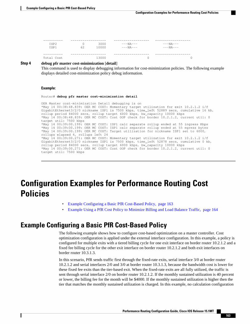
---------- ------------------ ------------------ ------------------ ISP2 0 3000 ---NA--- ---NA--- ISP1 62 10000 ---NA--- ---NA--- ---------- ------------------ ------------------ ------------------ Total Cost 13000 0 0
Step 4 debug pfr master cost-minimization [detail]This command is used to display debugging information for cost-minimization policies. The following exampledisplays detailed cost-minimization policy debug information.
Example:
Router# debug pfr master cost-minimization detail
OER Master cost-minimization Detail debugging is on*May 14 00:38:48.839: OER MC COST: Momentary target utilization for exit 10.2.1.2 i/fGigabitEthernet3/2/0 nickname ISP1 is 7500 kbps, time_left 52889 secs, cumulative 16 kb,rollup period 84000 secs, rollup target 6000 kbps, bw_capacity 10000 kbps*May 14 00:38:48.839: OER MC COST: Cost OOP check for border 10.2.1.2, current util: 0target util: 7500 kbps*May 14 00:39:00.199: OER MC COST: ISP1 calc separate rollup ended at 55 ingress Kbps*May 14 00:39:00.199: OER MC COST: ISP1 calc separate rollup ended at 55 egress bytes*May 14 00:39:00.199: OER MC COST: Target utilization for nickname ISP1 set to 6000,rollups elapsed 4, rollups left 24*May 14 00:39:00.271: OER MC COST: Momentary target utilization for exit 10.2.1.2 i/fGigabitEthernet3/2/0 nickname ISP1 is 7500 kbps, time_left 52878 secs, cumulative 0 kb,rollup period 84000 secs, rollup target 6000 kbps, bw_capacity 10000 kbps*May 14 00:39:00.271: OER MC COST: Cost OOP check for border 10.2.1.2, current util: 0target util: 7500 kbps
Configuration Examples for Performance Routing CostPolicies
• Example Configuring a Basic PfR Cost-Based Policy, page 163
• Example Using a PfR Cost Policy to Minimize Billing and Load Balance Traffic, page 164
Example Configuring a Basic PfR Cost-Based PolicyThe following example shows how to configure cost-based optimization on a master controller. Costoptimization configuration is applied under the external interface configuration. In this example, a policy isconfigured for multiple exits with a tiered billing cycle for one exit interface on border router 10.2.1.2 and afixed fee billing cycle for the other exit interface on border router 10.2.1.2 and both exit interfaces onborder router 10.3.1.3.
In this scenario, PfR sends traffic first through the fixed-rate exits, serial interface 3/0 at border router10.2.1.2 and serial interfaces 2/0 and 3/0 at border router 10.3.1.3, because the bandwidth cost is lower forthese fixed fee exits than the tier-based exit. When the fixed-rate exits are all fully utilized, the traffic issent through serial interface 2/0 on border router 10.2.1.2. If the monthly sustained utilization is 40 percentor lower, the billing fee for the month will be $4000. If the monthly sustained utilization is higher then thetier that matches the monthly sustained utilization is charged. In this example, no calculation configuration
Example Configuring a Basic PfR Cost-Based PolicyConfiguration Examples for Performance Routing Cost Policies
Performance Routing Configuration Guide, Cisco IOS Release 15.1MT 163

was entered and the default behavior is triggered; the calculation is performed separately for egress andingress samples.
This configuration example assumes that the border routers are already configured.
pfr master no periodic resolve cost priority 1 no resolve delay no resolve utilization border 10.2.1.2 key-chain key_cost1 interface Serial12/0 external cost-minimization tier 100 fee 10000 cost-minimization tier 75 fee 8000 cost-minimization tier 40 fee 4000 cost-minimization end day-of-month 31 interface Serial13/0 external cost-minimization fixed fee 3000 border 10.3.1.3 key-chain key_cost2 interface Serial12/0 external cost-minimization fixed fee 3000 interface Serial13/0 external cost-minimization fixed fee 3000 end
Example Using a PfR Cost Policy to Minimize Billing and Load BalanceTraffic
The following configuration example shows how to configure cost-minimization policies and balance PfRtraffic loads across multiple links. This task is designed to minimize the cost of each link and to preciselycontrol load balancing across multiple border router links. This task controls the load balancing betweenmultiple links by forcing PfR to use the bandwidth of the lowest cost tier first and then use the next lowestcost tiers on all the links.
Keywords in the show pfr master cost-minimization command are used to view the utilization of aspecific link with the monthly egress and ingress rollup values. After the monthly billing period endsanother keyword option for the billing history shows the sustained monthly utilization and link cost.
Border Router 10.1.1.1
key chain key1 key 1 key-string border1!pfr border logging local GigabitEthernet3/0/0 master 10.1.1.1 key-chain key1
Don’t forget to configure all the border routers using a similar configuration but with appropriate changes.Now configure the master controller.
Master Controller
key chain key1 key 1 key-string border1 key chain key2 key 1 key-string border2 key chain key3 key 1
Example Using a PfR Cost Policy to Minimize Billing and Load Balance Traffic Configuration Examples for Performance Routing Cost Policies
Performance Routing Configuration Guide, Cisco IOS Release 15.1MT164

key-string border3 pfr master logging border 10.1.1.1 key-chain key1 interface GigabitEthernet3/0/0 external cost-minimization nickname ISP1 cost-minimization tier 100 fee 50000 cost-minimization tier 65 fee 10000 cost-minimization tier 30 fee 500 cost-minimization end day-of-month 24 cost-minimization sampling period 5 rollup 1440 cost-minimization discard absolute 10 exit interface GigabitEthernet3/0/1 internal exit border 10.2.1.2 key-chain key2 interface GigabitEthernet3/2/0 external interface GigabitEthernet3/0/0 internal exit border 10.4.1.4 key-chain key3 interface GigabitEthernet4/0/0 external cost-minimization nickname ISP2 cost-minimization fixed fee 3000 cost-minimization end day-of-month 24 exit interface GigabitEthernet4/0/2 internal exit no max range receive delay threshold 10000 loss threshold 1000000 mode route control mode monitor passive mode select-exit best resolve cost priority 1 active-probe echo 10.1.9.1 end
Now enter the show pfr master cost-minimization border command at the master controller to show theconfiguration and the utilization statistics. The rollup values during the 30-day March through April 24thbilling period for the GigabitEthernet interface 3/0/0 on border router 10.1.1.1 are shown in the output:
Router# show pfr master cost-minimization border 10.1.1.1pM - per Month, pD - per Day -------------------------------------------------------------------------------- Nickname : ISP1 Border: 10.1.1.1 Interface: Gi3/0/0 Calc type : Separate End Date : 24 Summer time: Disabled Fee : Tier Based Tier 1: 100, fee: 50000 Tier 2: 65, fee: 10000 Tier 3: 30, fee: 500 Period : Sampling 5, Rollup 1440 Discard : Type Absolute, Value 10 Rollup Information: Total(pM) Discard(pM) Remaining(pM) Collected(pM) 31 10 1 29 Current Rollup Information: MomentaryTgtUtil: 75 Kbps CumRxBytes: 0 StartingRollupTgt: 75 Kbps CumTxBytes: 0 CurrentRollupTgt: 75 Kbps TimeRemain: 00:00:51 Rollup Utilization (Kbps): Egress Utilization Rollups (Descending order) 1 : 0 2 : 89 3 : 80 4 : 71 5 : 70 6 : 65 7 : 65 8 : 51 9 : 50 10 : 49 11 : 49 12 : 45 13 : 42 14 : 39 15 : 35 16 : 34 17 : 30 18 : 30 19 : 30 20 : 29
Configuring Performance Routing Cost PoliciesConfiguration Examples for Performance Routing Cost Policies
Performance Routing Configuration Guide, Cisco IOS Release 15.1MT 165

21 : 25 22 : 20 23 : 19 24 : 12 25 : 10 26 : 10 27 : 9 28 : 8 29 : 4 30 : 1 Ingress Utilization Rollups (Descending order) 1 : 0 2 : 92 3 : 84 4 : 82 5 : 80 6 : 78 7 : 75 8 : 73 9 : 72 10 : 70 11 : 63 12 : 62 13 : 60 14 : 55 15 : 53 16 : 52 17 : 45 18 : 43 19 : 35 20 : 33 21 : 31 22 : 25 23 : 23 24 : 21 25 : 15 26 : 11 27 : 10 28 : 10 29 : 5 30 : 1
If we assume that the March through April 24th billing period is over, we can see the billing for theprevious billing period using the show pfr master cost-minimization billing-history command. Themonthly sustained utilization is 62 and the cost is $10,000 for the GigabitEthernet interface 3/0/0 link onborder router 10.1.1.1.
Router# show pfr master cost-minimization billing-historyBilling History for the past three months ISP2 on 10.4.1.4 Gi4/0/0 No cost min on 10.2.1.2 Gi3/2/0 ISP1 on 10.1.1.1 Gi3/0/0 Mon1 Mon2 Mon3 Nickname SustUtil Cost SustUtil Cost SustUtil Cost ---------- ------------------ ------------------ ------------------ ISP2 0 3000 ---NA--- ---NA--- ISP1 62 10000 ---NA--- ---NA--- ---------- ------------------ ------------------ ------------------ Total Cost 13000 0 0
Where to Go NextIf you want to review more information about PfR, see the documents that are listed under “RelatedDocuments” section.
Additional ReferencesRelated Documents
Related Topic Document Title
Cisco IOS commands Cisco IOS Master Commands List, All Releases
Cisco PfR commands: complete command syntax,command mode, command history, defaults, usageguidelines and examples
Cisco IOS Performance Routing CommandReference
Basic PfR configuration "Configuring Basic Performance Routing" module
Concepts required to understand the PerformanceRouting operational phases
"Understanding Performance Routing" module
Configuring Performance Routing Cost Policies Where to Go Next
Performance Routing Configuration Guide, Cisco IOS Release 15.1MT166

Related Topic Document Title
Advanced PfR configuration "Configuring Advanced Performance Routing"module
IP SLAs overview IP SLAs Configuration Guide
Technical Assistance
Description Link
The Cisco Support and Documentation websiteprovides online resources to downloaddocumentation, software, and tools. Use theseresources to install and configure the software andto troubleshoot and resolve technical issues withCisco products and technologies. Access to mosttools on the Cisco Support and Documentationwebsite requires a Cisco.com user ID andpassword.
http://www.cisco.com/cisco/web/support/index.html
Feature Information for Configuring Performance Routing CostPolicies
The following table provides release information about the feature or features described in this module.This table lists only the software release that introduced support for a given feature in a given softwarerelease train. Unless noted otherwise, subsequent releases of that software release train also support thatfeature.
Use Cisco Feature Navigator to find information about platform support and Cisco software image support.To access Cisco Feature Navigator, go to www.cisco.com/go/cfn. An account on Cisco.com is not required.
Configuring Performance Routing Cost PoliciesFeature Information for Configuring Performance Routing Cost Policies
Performance Routing Configuration Guide, Cisco IOS Release 15.1MT 167

Table 7 Feature Information for Configuring Performance Routing Cost Policies
Feature Name Releases Feature Configuration Information
OER Support for Cost-BasedOptimization
12.3(14)T 12.2(33)SRB12.4(15)T9
The OER Support for Cost-BasedOptimization feature introducedthe capability to configure exitlink policies based monetary costand the capability to configuretraceroute probes to determineprefix characteristics on a hop-by-hop basis.
In Cisco IOS Release 12.4(15)T9and later releases, the calculationof the MTLU algorithm ismodified to allow for moreefficient bandwidth utilizationwhile minimizing the link cost.
The following commands wereintroduced or modified by thisfeature: cost-minimization(PfR), debug pfr master cost-minimization,show pfr mastercost-minimization.
Cisco and the Cisco Logo are trademarks of Cisco Systems, Inc. and/or its affiliates in the U.S. and othercountries. A listing of Cisco's trademarks can be found at www.cisco.com/go/trademarks. Third partytrademarks mentioned are the property of their respective owners. The use of the word partner does notimply a partnership relationship between Cisco and any other company. (1005R)
Any Internet Protocol (IP) addresses and phone numbers used in this document are not intended to beactual addresses and phone numbers. Any examples, command display output, network topology diagrams,and other figures included in the document are shown for illustrative purposes only. Any use of actual IPaddresses or phone numbers in illustrative content is unintentional and coincidental.
Configuring Performance Routing Cost Policies
Performance Routing Configuration Guide, Cisco IOS Release 15.1MT168

Using Performance Routing to Control EIGRPRoutes with mGRE DMVPN Hub-and-SpokeSupport
The PfR EIGRP mGRE DMVPN Hub-and-Spoke Support feature introduces the ability to inject routesinto the EIGRP routing table, which allows Performance Routing (PfR) to control prefixes andapplications over EIGRP routes. This feature also adds support for multipoint Generic RoutingEncapsulation (mGRE) Dynamic Multipoint Virtual Private Network (DMVPN) deployments that followa hub-and-spoke network design.
• Finding Feature Information, page 169• Prerequisites for Using PfR to Control EIGRP Routes, page 169• Restrictions for Using PfR to Control EIGRP Routes, page 170• Information About Using PfR to Control EIGRP Routes, page 170• How to Configure PfR to Control EIGRP Routes, page 173• Configuration Examples for Using PfR to Control EIGRP Routes, page 177• Where to Go Next, page 178• Additional References, page 178• Feature Information for Using PfR to Control EIGRP Routes, page 179
Finding Feature InformationYour software release may not support all the features documented in this module. For the latest featureinformation and caveats, see the release notes for your platform and software release. To find informationabout the features documented in this module, and to see a list of the releases in which each feature issupported, see the Feature Information Table at the end of this document.
Use Cisco Feature Navigator to find information about platform support and Cisco software image support.To access Cisco Feature Navigator, go to www.cisco.com/go/cfn. An account on Cisco.com is not required.
Prerequisites for Using PfR to Control EIGRP RoutesThis feature assumes that EIGRP is already configured in your network and that basic PfR functionality isalso configured.
Performance Routing Configuration Guide, Cisco IOS Release 15.1MT 169

Restrictions for Using PfR to Control EIGRP Routes• PfR does not support split tunneling.• PfR supports hub-to-spoke links only. Spoke-to-spoke links are not supported. If you are deploying
EIGRP in an mGRE DMVPN topology in your network, it must conform to a hub-and-spoke networkdesign.
• PfR is supported on DMVPN Multipoint GRE (mGRE) deployments. Any multipoint interfacedeployment that has multiple next hops for the same destination IP address is not supported (forexample, Ethernet).
Information About Using PfR to Control EIGRP Routes• PfR EIGRP Route Control, page 170• PfR and mGRE Dynamic Multipoint VPN, page 171
PfR EIGRP Route ControlThe PfR EIGRP mGRE DMVPN Hub-and-Spoke Support feature introduces PfR route control for EIGRP.When enabled, a parent route check is performed in the EIGRP database for controlling PfR prefixes androutes in addition to the existing BGP and static route databases.
PfR can only optimize paths for prefixes, which have an exact matching route or a less specific route (alsocalled as parent route) in the routing protocols. The route being controlled by PfR can be an exact match ofthe parent route or can be a more specific one. For example, if PfR wants to control 10.1.1.0/24 but theEIGRP routing table has only 10.1.0.0/16 then the parent route is 10.1.0.0/16 and PfR will inject10.1.1.0/24 in the EIGRP routing table.
If an exact matching parent route in the EIGRP routing table is found, PfR will attempt to install a route onan exit selected by the master controller by influencing the metric. If an exact match parent is not found,then PfR introduces a new route in the EIGRP table that matches the attributes of the parent. If the routeinstallation in the EIGRP table is successful, PfR saves the EIGRP parent and registers for any updates tothe parent route. If the parent route is removed, PfR will uncontrol any routes it has installed in the EIGRPtable based on this parent route.
PfR monitors traffic performance for prefixes it is controlling either passively using NetFlow or activelyusing IP SLA probes. Performance statistics such as delay, loss, and reachability are gathered andcompared against a set of policies configured for the prefixes. If the traffic performance does not conformto the policies, the prefix is said to be out-of-policy (OOP). PfR tries to find an alternate path when theprefix goes into the OOP state.
While both BGP and static route control are enabled by default, EIGRP route control must be configured.PfR always attempts to control a prefix using BGP first. If BGP route control fails, static route control istried. When EIGRP route control is enabled, PfR will attempt to control a prefix using BGP first. If noparent route is found, PfR will try to use EIGRP route control. If EIGRP route controls fails, static routecontrol is tried.
To find an alternate path for a prefix, PfR tries to send active probes from all the external interfaces on theborder routers to a set of hosts in the destination prefix network. Before an active probe can be sent on anexternal interface, a parent route lookup is performed in routing protocol tables. When the PfR EIGRPmGRE DMVPN Hub-and-Spoke Support feature is enabled, PfR checks EIGRP routing tables, in additionto BGP and static routing tables, for a parent route, before sending active probes on external interfaces.
PfR EIGRP Route Control Restrictions for Using PfR to Control EIGRP Routes
Performance Routing Configuration Guide, Cisco IOS Release 15.1MT170

Active probes are initiated on all the external interfaces that have a parent route in the EIGRP routing table.When the probe activity completes and the timer expires, statistics are sent from the border router to themaster controller for policy decision and selection of an optimal exit.
When an exit is selected, a control prefix command is sent to the border router with the selected exit,specifying EIGRP as the protocol to install or modify the route. When the border router receives thecommand, it checks the EIGRP table to find a parent route. If a parent route is found, PfR will install ormodify the route in the EIGRP table and will notify the master controller about the route control status.
If an EIGRP route is successfully installed and advertised into the domain, PfR continues to monitor trafficperformance for this prefix and takes further action as mentioned above if the prefix goes OOP.
For more details about the PfR control mode and details about other PfR exit link selection controltechniques including BGP, static routes, policy-based routing, and Protocol Independent RouteOptimization (PIRO), see the Understanding Performance Routing module and the Performance Routing -Protocol Independent Route Optimization (PIRO) module.
PfR and mGRE Dynamic Multipoint VPNPerformance Routing is supported on mGRE interfaces in Dynamic Multipoint VPN (DMVPN) topologies.DMVPN enables zero-touch deployment of IPsec encrypted VPN networks. Many DMVPN deploymentsuse EIGRP networks, and support was added to PfR to allow DMVPN network deployments to use EIGRProute control within the DMVPN network. In the PfR EIGRP route control implementation, only hub-to-spoke network designs are supported.
In DMVPN topologies the mGRE interface works as a one-to-many interface and allows the dynamiccreation of tunnels for each connected branch.
The figure below shows a typical dual DMVPN topology. The head office (R2) has one hub (hub1) thatconnects to the remote site spokes using one of the DMVPN networks (DMVPN 1 or DMVPN 2) or theMPLS-GETVPN network.
Remote site 1 (RS1) has spokes 1 and 2 that connect to the hub using the DMVPN1 and DMVPN2networks. Remote site 2 (RS2) has spoke 3 and connects to the hub using DMVPN1 network only. Thismeans that there is no redundancy at RS2 and any performance optimization is performed between the hub
PfR and mGRE Dynamic Multipoint VPNInformation About Using PfR to Control EIGRP Routes
Performance Routing Configuration Guide, Cisco IOS Release 15.1MT 171

and RS2 only. Remote site 3 (RS3) has spoke 3 that connects to the hub using the DMVPN2 network andthe MPLS-GETVPN network.
Figure 12 PfR Dual DMVPN Topology
Spoke1
192.168.1.0/24
.1
192.168.0.0/24
.2.1
.3
192.168.10.0/24
.2
RS1
.1
192.168.11.0/24
2buH1buH
Spoke2
192.168.2.0/24
.1
.2
RS2
.1
192.168.12.0/24
Spoke3
192.168.3.0/24
.1
.2
RS3
.1
192.168.13.0/24
.1
.1
.11
.12
.13
.2
.11
.12
.13
InterfaceTunnel 0
InterfaceTunnel 1
R2
DMVPN 110.0.0.0/24
DMVPN 210.0.1.0/24
24
88
84
When PfR is configured on the network, the system can perform these functions:
• Control and measure the performance of PfR traffic-classes on mGRE interfaces.• Support load balancing for traffic over multipoint interfaces that are configured as PfR external
interfaces. For example, in topologies with two DMVPN clouds PfR can be configured to load balancethe traffic across the two tunnel interfaces to ensure that network performance is maintained.
• Reroute traffic from or to a multipoint interface for better performance. For example, PfR policies canbe configured to select the best path to a spoke and the best path from the spoke to the hub.
• Provide a back-up connection if the primary connection fails. For example, in a topology with oneMPLS-GETVPN and one DMVPN connection, the MPLS-GETVPN could act as a primaryconnection and PfR could be configured to use the DMVPN connection if the primary connectionfails.
The DMVPN topology leverages protocols like multipoint GRE (mGRE) for hub-to-spoke functionality,and for spoke-to-spoke functionality it utilizes the Next Hop Resolution Protocol (NHRP). For more detailsabout configuring mGRE DMVPN networks, see the "Dynamic Multipoint VPN" module in the Cisco IOSSecurity Configuration Guide: Secure Connectivity. For general information about DMVPN, go to http://www.cisco.com/go/dmvpn.
Using Performance Routing to Control EIGRP Routes with mGRE DMVPN Hub-and-Spoke Support Information About Using PfR to Control EIGRP Routes
Performance Routing Configuration Guide, Cisco IOS Release 15.1MT172

How to Configure PfR to Control EIGRP Routes• Enabling PfR EIGRP Route Control and Setting a Community Value, page 173
• Disabling PfR EIGRP Route Control, page 174
• Manually Verifying the PfR EIGRP-Controlled Routes, page 175
Enabling PfR EIGRP Route Control and Setting a Community ValuePerform this task on the master controller to enable EIGRP route control. While both BGP and static routecontrol are enabled by default, EIGRP route control must be enabled using a command-line interface (CLI)command, mode route metric eigrp. PfR always attempts to control a prefix using BGP first. If BGP routecontrol fails, static route control is tried. When EIGRP route control is enabled, PfR will attempt to controla prefix using BGP first. If no parent route is found, PfR will try to use EIGRP route control. If EIGRProute controls fails, static route control is tried.
This task can also set an extended community value for an injected EIGRP route to allow the routes to beuniquely identified. An EIGRP route may be injected by PfR to control the traffic defined by a traffic classwhen it goes out-of-policy (OOP). In this task, the PfR route control mode is configured globally with themode route control command in PfR master controller configuration mode, and any injected EIGRProutes will be tagged with a value of 700.
SUMMARY STEPS
1. enable
2. configure terminal
3. pfr master
4. mode route control
5. mode route metric eigrp tag community
6. end
DETAILED STEPS
Command or Action Purpose
Step 1 enable
Example:
Router> enable
Enables privileged EXEC mode.
• Enter your password if prompted.
Step 2 configure terminal
Example:
Router# configure terminal
Enters global configuration mode.
Enabling PfR EIGRP Route Control and Setting a Community ValueHow to Configure PfR to Control EIGRP Routes
Performance Routing Configuration Guide, Cisco IOS Release 15.1MT 173

Command or Action Purpose
Step 3 pfr master
Example:
Router(config)# pfr master
Enters PfR master controller configuration mode to configure a router asa master controller and to configure global operations and policies.
Step 4 mode route control
Example:
Router(config-pfr-mc)# mode route control
Configures the PfR route control mode on a master controller.
• The routeand control keywords enable route control mode. Incontrol mode, the master controller analyzes monitored trafficclasses and implements changes based on policy parameters.
Step 5 mode route metric eigrp tag community
Example:
Router(config-pfr-mc)# mode route metric eigrp tag 7000
Enables EIGRP route control and sets an EIGRP tag and communitynumber value for injected EIGRP routes.
• Use the tag keyword to apply a tag to an EIGRP route under PfRcontrol. Thecommunity argument is a number from 1 to 65535.
Step 6 end
Example:
Router(config-pfr-mc)# end
Exits PfR master controller configuration mode and returns to privilegedEXEC mode.
Disabling PfR EIGRP Route Control
Note When this task is complete, PfR withdraws all the routes that are being controlled using the EIGRPprotocol.
SUMMARY STEPS
1. enable
2. configure terminal
3. pfr master
4. no mode route metric eigrp
5. end
Disabling PfR EIGRP Route Control How to Configure PfR to Control EIGRP Routes
Performance Routing Configuration Guide, Cisco IOS Release 15.1MT174

DETAILED STEPS
Command or Action Purpose
Step 1 enable
Example:
Router> enable
Enables privileged EXEC mode.
• Enter your password if prompted.
Step 2 configure terminal
Example:
Router# configure terminal
Enters global configuration mode.
Step 3 pfr master
Example:
Router(config)# pfr master
Enters PfR master controller configuration mode to configure arouter as a master controller and to configure global operationsand policies.
Step 4 no mode route metric eigrp
Example:
Router(config-pfr-mc)# no mode route metric eigrp
Disables EIGRP route control and removes all the routes thatare being controlled using the EIGRP protocol.
Step 5 end
Example:
Router(config-pfr-mc)# end
Exits PfR master controller configuration mode and returns toprivileged EXEC mode.
Manually Verifying the PfR EIGRP-Controlled RoutesPfR automatically verifies route control changes in the network using NetFlow output. PfR monitors theNetFlow messages and uncontrols a traffic class if a message does not appear to verify the route controlchange. Perform the steps in this optional task if you want to manually verify that the traffic controlimplemented in the PfR control phase actually changes the traffic flow, and brings the OOP event to be in-policy.
All the steps in this task are optional and are not in any order. The information from these steps can verifythat a specific prefix associated with a traffic class has been moved to another exit or entrance linkinterface, or that it is being controlled by PfR. The first two commands are entered at the master controller,the last two commands are entered at a border router.
Only partial command syntax for some of the show commands used in this task is displayed. For moredetails about PfR show commands, see the Cisco IOS Performance Routing Command Reference.
Manually Verifying the PfR EIGRP-Controlled RoutesHow to Configure PfR to Control EIGRP Routes
Performance Routing Configuration Guide, Cisco IOS Release 15.1MT 175

This task assumes that you have previously enabled EIGRP route control using PfR.
SUMMARY STEPS
1. enable
2. show pfr master prefix prefix [detail]
3. Move to a border router to enter the next step.
4. enable
5. show pfr border routes eigrp [parent]
DETAILED STEPS
Step 1 enableEnables privileged EXEC mode. Enter your password if prompted.
Example:
Router> enable
Step 2 show pfr master prefix prefix [detail]This command is used to display the status of monitored prefixes. The output from this command includesinformation about the source border router, current exit interface, protocol, prefix delay, and egress and ingressinterface bandwidth. In this example, the protocol displayed for the prefix 10.1.0.0/16 is EIGRP, which means that theparent route for the traffic class exists in the EIGRP routing table and EIGRP community values are used to controlthe prefix. Only syntax relevant to this task is shown in this step.
Example:
Router# show pfr master prefix 10.1.0.0
OER Prefix Statistics: Pas - Passive, Act - Active, S - Short term, L - Long term, Dly - Delay (ms), P - Percentage below threshold, Jit - Jitter (ms), MOS - Mean Opinion Score Los - Packet Loss (packets-per-million), Un - Unreachable (flows-per-million), E - Egress, I - Ingress, Bw - Bandwidth (kbps), N - Not applicable U - unknown, * - uncontrolled, + - control more specific, @ - active probe all # - Prefix monitor mode is Special, & - Blackholed Prefix % - Force Next-Hop, ^ - Prefix is deniedPrefix State Time Curr BR CurrI/F Protocol PasSDly PasLDly PasSUn PasLUn PasSLos PasLLos ActSDly ActLDly ActSUn ActLUn EBw IBw ActSJit ActPMOS--------------------------------------------------------------------------------10.1.0.0/16 DEFAULT* @69 10.1.1.1 Gi1/22 EIGRP U U 0 0 0 0 U U 0 0 22 8 N N
Step 3 Move to a border router to enter the next step.The next command is entered on a border router, not the master controller.
Example:
Step 4 enable
Using Performance Routing to Control EIGRP Routes with mGRE DMVPN Hub-and-Spoke Support How to Configure PfR to Control EIGRP Routes
Performance Routing Configuration Guide, Cisco IOS Release 15.1MT176

Enables privileged EXEC mode. Enter your password if prompted.
Example:
Router> enable
Step 5 show pfr border routes eigrp [parent]This command is entered on a border router. Use this command to display information about EIGRP routes controlledby PfR on a border router. In this example, the output shows that prefix 10.1.2.0/24 is being controlled by PfR. Thiscommand is used to show parent route lookup and route changes to existing parent routes when the parent route isidentified from the EIGRP routing table.
Example:
Router# show pfr border routes eigrp
Flags: C - Controlled by oer, X - Path is excluded from control, E - The control is exact, N - The control is non-exactFlags Network Parent Tag CE 10.1.2.0/24 10.0.0.0/8 5000
In this example, the parent keyword is used and more details are shown about the parent route lookup.
Example:
Router# show pfr border routes eigrp parent
Network Gateway Intf Flags 10.0.0.0/8 10.40.40.2 Gi0/0/2 1 Child NetworksNetwork Flag10.1.2.0/24 6
• Troubleshooting Tips, page 177
Troubleshooting TipsIf the show commands are not displaying output that verifies the EIGRP route control, use the debug pfrborder routes eigrp command with the optional detail keyword for more information. Debugging must beenabled before entering the required commands, and the debug output depends on which commands aresubsequently entered.
Configuration Examples for Using PfR to Control EIGRPRoutes
• Example Enabling PfR EIGRP Route Control and Setting a Community Value, page 178
Using Performance Routing to Control EIGRP Routes with mGRE DMVPN Hub-and-Spoke SupportTroubleshooting Tips
Performance Routing Configuration Guide, Cisco IOS Release 15.1MT 177

Example Enabling PfR EIGRP Route Control and Setting a Community ValueIn the following configuration example, PfR route control is enabled first, and then the EIGRP routecontrol is enabled and configured to set an extended community value of 700 to any injected EIGRP routes:
pfr master mode route control mode route metric eigrp tag 700 end
Where to Go NextThis module covers PfR EIGRP route control and presumes that you are familiar with the PfR technology.If you want to review more information about PfR, see the documents that are listed under "RelatedDocuments" section.
Additional ReferencesRelated Documents
Related Topic Document Title
Cisco IOS commands Cisco IOS Master Commands List, All Releases
Cisco PfR commands: complete command syntax,command mode, command history, defaults, usageguidelines and examples
Cisco IOS Performance Routing CommandReference
Basic PfR configuration "Configuring Basic Performance Routing" module
Advanced PfR configuration "Configuring Advanced Performance Routing"module
Concepts required to understand the PerformanceRouting operational phases
"Understanding Performance Routing" module
EIGRP Routing Protocol commands Cisco IOS IP Routing: EIGRP Command Reference
Configuring mGRE DMVPN networks "Dynamic Multipoint VPN"
General information about the DMVPN technology http://www.cisco.com/go/dmvpn
Command Lookup Tool http://tools.cisco.com/Support/CLILookup
Example Enabling PfR EIGRP Route Control and Setting a Community Value Where to Go Next
Performance Routing Configuration Guide, Cisco IOS Release 15.1MT178

Technical Assistance
Description Link
The Cisco Support website provides extensiveonline resources, including documentation and toolsfor troubleshooting and resolving technical issueswith Cisco products and technologies.
To receive security and technical information aboutyour products, you can subscribe to variousservices, such as the Product Alert Tool (accessedfrom Field Notices), the Cisco Technical ServicesNewsletter, and Really Simple Syndication (RSS)Feeds.
Access to most tools on the Cisco Support websiterequires a Cisco.com user ID and password.
http://www.cisco.com/cisco/web/support/index.html
Feature Information for Using PfR to Control EIGRP RoutesThe following table provides release information about the feature or features described in this module.This table lists only the software release that introduced support for a given feature in a given softwarerelease train. Unless noted otherwise, subsequent releases of that software release train also support thatfeature.
Use Cisco Feature Navigator to find information about platform support and Cisco software image support.To access Cisco Feature Navigator, go to www.cisco.com/go/cfn. An account on Cisco.com is not required.
Table 8 Feature Information for Using PfR to Control EIGRP Routes
Feature Name Releases Feature Information
PfR EIGRP mGRE DMVPNHub-and-Spoke Support
12.2(33)SRE 15.0(1)M 15.0(1)S The PfR EIGRP featureintroduces PfR route controlcapabilities based on EIGRP byperforming a route parent checkon the EIGRP database. Thisfeature also adds support formGRE Dynamic Multipoint VPN(DMVPN) deployments thatfollow a hub-and-spoke networkdesign.
The following commands wereintroduced or modified: debugpfr border routes, mode (PfR),show pfr border routes, andshow pfr master prefix.
Using Performance Routing to Control EIGRP Routes with mGRE DMVPN Hub-and-Spoke SupportFeature Information for Using PfR to Control EIGRP Routes
Performance Routing Configuration Guide, Cisco IOS Release 15.1MT 179

Cisco and the Cisco Logo are trademarks of Cisco Systems, Inc. and/or its affiliates in the U.S. and othercountries. A listing of Cisco's trademarks can be found at www.cisco.com/go/trademarks. Third partytrademarks mentioned are the property of their respective owners. The use of the word partner does notimply a partnership relationship between Cisco and any other company. (1005R)
Any Internet Protocol (IP) addresses and phone numbers used in this document are not intended to beactual addresses and phone numbers. Any examples, command display output, network topology diagrams,and other figures included in the document are shown for illustrative purposes only. Any use of actual IPaddresses or phone numbers in illustrative content is unintentional and coincidental.
Using Performance Routing to Control EIGRP Routes with mGRE DMVPN Hub-and-Spoke Support
Performance Routing Configuration Guide, Cisco IOS Release 15.1MT180

Performance Routing Link Groups
The Performance Routing - Link Groups feature introduced the ability to define a group of exit links as apreferred set of links, or a fallback set of links for Performance Routing (PfR) to use when optimizingtraffic classes specified in a PfR policy.
• Finding Feature Information, page 181• Information About Performance Routing Link Groups, page 181• How to Configure Performance Routing Link Groups, page 183• Configuration Examples for Performance Routing Link Groups, page 188• Where to Go Next, page 188• Additional References, page 188• Feature Information for Performance Routing Link Groups, page 189
Finding Feature InformationYour software release may not support all the features documented in this module. For the latest featureinformation and caveats, see the release notes for your platform and software release. To find informationabout the features documented in this module, and to see a list of the releases in which each feature issupported, see the Feature Information Table at the end of this document.
Use Cisco Feature Navigator to find information about platform support and Cisco software image support.To access Cisco Feature Navigator, go to www.cisco.com/go/cfn. An account on Cisco.com is not required.
Information About Performance Routing Link Groups• Performance Routing Link Grouping, page 181
Performance Routing Link GroupingThe Performance Routing - Link Groups feature introduced the ability to define a group of exit links as apreferred set of links, or a fallback set of links for PfR to use when optimizing traffic classes specified in anPfR policy. PfR currently selects the best link for a traffic class based on the preferences specified in apolicy and the traffic class performance--using parameters such as reachability, delay, loss, jitter or MOS--on a path out of the specified link. Bandwidth utilization, cost, and the range of links can also be consideredin selecting the best link. Link grouping introduces a method of specifying preferred links for one or moretraffic classes in an PfR policy so that the traffic classes are routed through the best link from a list ofpreferred links, referred to as the primary link group. A fallback link group can also be specified in casethere are no links in the primary group that satisfy the specified policy and performance requirements. If no
Performance Routing Configuration Guide, Cisco IOS Release 15.1MT 181
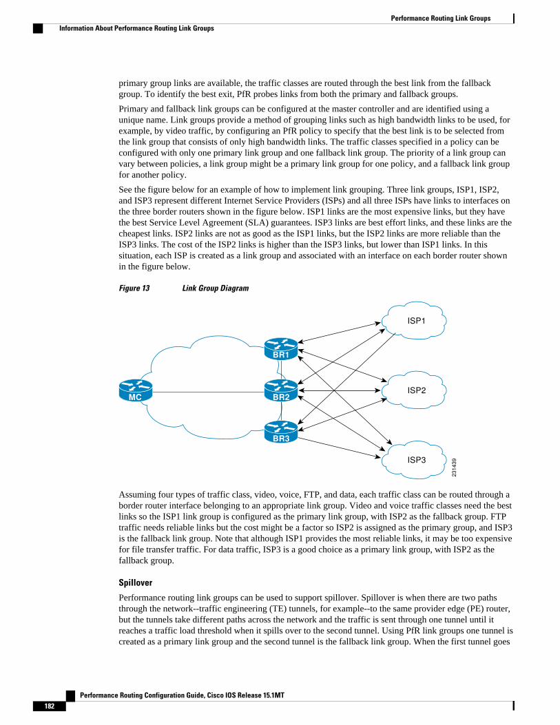
primary group links are available, the traffic classes are routed through the best link from the fallbackgroup. To identify the best exit, PfR probes links from both the primary and fallback groups.
Primary and fallback link groups can be configured at the master controller and are identified using aunique name. Link groups provide a method of grouping links such as high bandwidth links to be used, forexample, by video traffic, by configuring an PfR policy to specify that the best link is to be selected fromthe link group that consists of only high bandwidth links. The traffic classes specified in a policy can beconfigured with only one primary link group and one fallback link group. The priority of a link group canvary between policies, a link group might be a primary link group for one policy, and a fallback link groupfor another policy.
See the figure below for an example of how to implement link grouping. Three link groups, ISP1, ISP2,and ISP3 represent different Internet Service Providers (ISPs) and all three ISPs have links to interfaces onthe three border routers shown in the figure below. ISP1 links are the most expensive links, but they havethe best Service Level Agreement (SLA) guarantees. ISP3 links are best effort links, and these links are thecheapest links. ISP2 links are not as good as the ISP1 links, but the ISP2 links are more reliable than theISP3 links. The cost of the ISP2 links is higher than the ISP3 links, but lower than ISP1 links. In thissituation, each ISP is created as a link group and associated with an interface on each border router shownin the figure below.
Figure 13 Link Group Diagram
ISP1
ISP2
ISP32
31
43
9
BR1
BR2MC
BR3
Assuming four types of traffic class, video, voice, FTP, and data, each traffic class can be routed through aborder router interface belonging to an appropriate link group. Video and voice traffic classes need the bestlinks so the ISP1 link group is configured as the primary link group, with ISP2 as the fallback group. FTPtraffic needs reliable links but the cost might be a factor so ISP2 is assigned as the primary group, and ISP3is the fallback link group. Note that although ISP1 provides the most reliable links, it may be too expensivefor file transfer traffic. For data traffic, ISP3 is a good choice as a primary link group, with ISP2 as thefallback group.
Spillover
Performance routing link groups can be used to support spillover. Spillover is when there are two pathsthrough the network--traffic engineering (TE) tunnels, for example--to the same provider edge (PE) router,but the tunnels take different paths across the network and the traffic is sent through one tunnel until itreaches a traffic load threshold when it spills over to the second tunnel. Using PfR link groups one tunnel iscreated as a primary link group and the second tunnel is the fallback link group. When the first tunnel goes
Performance Routing Link Groups Information About Performance Routing Link Groups
Performance Routing Configuration Guide, Cisco IOS Release 15.1MT182

out of policy, PfR switches to the fallback tunnel link group, which provides the spillover capacity until thetraffic load on the first tunnel drops below the threshold. The tunnels must be established before the PfRlink groups are configured.
How to Configure Performance Routing Link Groups• Implementing Performance Routing Link Groups, page 183
Implementing Performance Routing Link GroupsPerform this task on a master controller to set up some performance routing link groups by identifying anexit link on a border router as a member of a link group, and to create a PfR map to specify link groups fortraffic classes defined in a PfR policy. In this task, a link group is set up for video traffic and a set of highbandwidth exit links are identified as members of the video link group which is identified as a primary linkgroup. A fallback link group is also specified.
A PfR policy is created using an PfR map where the primary and fall link groups are specified for trafficclasses matching the PfR map criteria. PfR probes both the primary and fallback group links and selects thebest link in the primary link group for the traffic class specified in this task. If none of the primary links arewithin policy, PfR selects the bast link from the fallback group. For more details about link groups, see the“Performance Routing Link Grouping” section.
Note If you are configuring link grouping, configure the no max-range-utilization command because using alink utilization range is not compatible with using a preferred or fallback set of exit links configured forlink grouping.
Implementing Performance Routing Link GroupsHow to Configure Performance Routing Link Groups
Performance Routing Configuration Guide, Cisco IOS Release 15.1MT 183

SUMMARY STEPS
1. enable
2. configure terminal
3. pfr master
4. border ip-address [key-chain key-chain-name]
5. interface type number external
6. link-group link-group-name [link-group-name [link-group-name]]
7. exit
8. Repeat Step 5 through Step 7 with appropriate changes to set up link groups for all the externalinterface.
9. interface type number internal
10. exit
11. ip access-list {standard | extended} access-list-name
12. [sequence-number] permit udp source source-wildcard [operator [port]] destination destination-wildcard [operator [port]] [dscp dscp-value]
13. Repeat Step 12 for more access list entries, as required.
14. exit
15. pfr-map map-name sequence-number
16. match traffic-class access-list access-list-name
17. set link-group link-group-name [fallback link-group-name]
18. end
19. show pfr master link-group [link-group-name]
DETAILED STEPS
Command or Action Purpose
Step 1 enable
Example:
Router> enable
Enables privileged EXEC mode.
• Enter your password if prompted.
Step 2 configure terminal
Example:
Router# configure terminal
Enters global configuration mode.
Step 3 pfr master
Example:
Router(config)# pfr master
Enters PfR master controller configuration mode to configure a router as amaster controller.
• A master controller and border router process can be enabled on the samerouter (for example, in a network that has a single router with two exit linksto different service providers).
Performance Routing Link Groups How to Configure Performance Routing Link Groups
Performance Routing Configuration Guide, Cisco IOS Release 15.1MT184

Command or Action Purpose
Step 4 border ip-address [key-chain key-chain-name]
Example:
Router(config-pfr-mc)# border 192.168.1.2 key-chain border1_PFR
Enters PfR-managed border router configuration mode to establishcommunication with a border router.
• An IP address is configured to identify the border router.• At least one border router must be specified to create a PfR-managed
network. A maximum of ten border routers can be controlled by a singlemaster controller.
• The value for the key-chain-name argument must match the key-chainname configured when the border router is set up.
Note The key-chain keyword and key-chain-name argument must be enteredwhen a border router is initially configured. However, this keyword isoptional when reconfiguring an existing border router.
Step 5 interface type number external
Example:
Router(config-pfr-mc-br)# interface Serial 2/0 external
Configures a border router interface as a PfR-managed external interface.
• External interfaces are used to forward traffic and for active monitoring.• A minimum of two external border router interfaces are required in a PfR-
managed network. At least one external interface must be configured oneach border router. A maximum of 20 external interfaces can be controlledby single master controller.
Tip Configuring an interface as a PfR-managed external interface on a routerenters PfR border exit interface configuration mode. In this mode, you canconfigure maximum link utilization or cost-based optimization for theinterface.
Note Entering the interface (PfR) command without the external orinternalkeyword places the router in global configuration mode and not PfRborder exit configuration mode. The no form of this command should beapplied carefully so that active interfaces are not removed from the routerconfiguration.
Step 6 link-group link-group-name [link-group-name [link-group-name]]
Example:
Router(config-pfr-mc-br-if)# link-group VIDEO
Configures a PfR border router exit interface as a member of a link group.
• Use the link-group-name to specify the link group name for the interface.• Up to three link groups can be specified for each interface.• In this example, the Serial 2/0 external interface is configured as a member
of the link group named VIDEO.
Note The link-group (PfR) command associates a link group with an interface.Another step, Implementing Performance Routing Link Groups, page183, uses the set link-group (PfR) command to identify the link group asa primary or fallback group for traffic classes defined in a PfR map.
Step 7 exit
Example:
Router(config-pfr-mc-br-if)# exit
Exits PfR-managed border exit interface configuration mode and returns to PfR-managed border router configuration mode.
Performance Routing Link GroupsHow to Configure Performance Routing Link Groups
Performance Routing Configuration Guide, Cisco IOS Release 15.1MT 185

Command or Action Purpose
Step 8 Repeat Step 5 through Step 7 withappropriate changes to set up linkgroups for all the external interface.
--
Step 9 interface type number internal
Example:
Router(config-pfr-mc-br)# interface FastEthernet 0/1 internal
Configures a border router interface as an PfR controlled internal interface.
• Internal interfaces are used for passive monitoring only. Internal interfacesdo not forward traffic.
• At least one internal interface must be configured on each border router.
Note Support to configure a VLAN interface as an internal interface wasintroduced in Cisco IOS Release 12.3(14)T and 12.2(33)SRB.
Step 10 exit
Example:
Router(config-pfr-mc-br)# exit
Exits PfR-managed border configuration mode and returns to globalconfiguration mode.
Step 11 ip access-list {standard | extended}access-list-name
Example:
Router(config)# ip access-list extended ACCESS_VIDEO
Defines an IP access list by name and enters extended named access listconfiguration mode.
• PfR supports only named access lists.• The example creates an extended IP access list named ACCESS_VIDEO.
Step 12 [sequence-number] permit udp sourcesource-wildcard [operator [port]]destination destination-wildcard[operator [port]] [dscp dscp-value]
Example:
Router(config-ext-nacl)# permit tcp any any 500
Sets conditions to allow a packet to pass a named IP access list.
• The example is configured to identify all TCP traffic from any destinationor source and from destination port number of 500. This specific TCPtraffic is to be optimized.
Step 13 Repeat Step 12 for more access listentries, as required.
--
Step 14 exit
Example:
Router(config-ext-nacl)# exit
(Optional) Exits extended named access list configuration mode and returns toglobal configuration mode.
Performance Routing Link Groups How to Configure Performance Routing Link Groups
Performance Routing Configuration Guide, Cisco IOS Release 15.1MT186

Command or Action Purpose
Step 15 pfr-map map-name sequence-number
Example:
Router(config)# pfr-map VIDEO_MAP 10
Enters PfR map configuration mode to configure a PfR map.
• Only one match clause can be configured for each PfR map sequence.• Permit sequences are first defined in an IP prefix list and then applied with
the match ip address (PfR) command in Step 16 .• The example creates n PfR map named VIDEO_MAP.
Step 16 match traffic-class access-list access-list-name
Example:
Router(config-pfr-map)# traffic-class access-list ACCESS_VIDEO
Manually configures an access list as match criteria used to create traffic classesusing a PfR map.
• Each access list entry must contain a destination prefix and may includeother optional parameters.
• The example defines a traffic class using the criteria defined in the accesslist named ACCESS_VIDEO.
Step 17 set link-group link-group-name[fallback link-group-name]
Example:
Router(config-pfr-map)# set link-group video fallback voice
Specifies a link group for traffic classes defined in a PfR map to create a PfRpolicy.
• Use the link-group-name to specify the primary link group name for thepolicy.
• Use the fallback keyword to specify the fallback link group name for thepolicy.
• The example specifies the VIDEO link group as the primary link group forthe traffic class matching the access list ACCESS_VIDEO. The link groupVOICE is specified as the fallback link group.
Step 18 end
Example:
Router(config-pfr-map)# end
(Optional) Exits PfR map configuration mode and returns to privileged EXECmode.
Step 19 show pfr master link-group [link-group-name]
Example:
Router# show pfr master link-group
Displays information about configured PfR link groups.
• Use the optional link-group-name argument to display information for thespecified PfR link group.
• If the link-group-name argument is not specified, information about all PfRlink groups is displayed.
• The example displays information about all configured link groups.
Example
The example output from the show pfr master link-group command displays information aboutperformance routing link groups configured using PfR. In this example, the VIDEO link group is shownwith other configured link groups.
Router# show pfr master link-grouplink group video Border Interface Exit id 192.168.1.2 Serial2/0 1
Performance Routing Link GroupsHow to Configure Performance Routing Link Groups
Performance Routing Configuration Guide, Cisco IOS Release 15.1MT 187

link group voice Border Interface Exit id 192.168.1.2 Serial2/0 1 192.168.1.2 Serial3/0 2 192.168.3.2 Serial4/0 4 link group data Border Interface Exit id 192.168.3.2 Serial3/0 3
Configuration Examples for Performance Routing Link Groups• Example Implementing Performance Routing Link Groups, page 188
Example Implementing Performance Routing Link GroupsThe following example shows how to implement link groups. In this example, a PfR map namedVIDEO_MAP is created to configure PfR to define a traffic class that matches an access list namedACCESS_VIDEO. The traffic class is configured to use a link group named VIDEO as the primary linkgroup, and a fallback group named VOICE. The VIDEO link group may be a set of high bandwidth linksthat are preferred for video traffic.
enableconfigure terminalborder 10.1.4.1 interface serial 2/0 external link-group VIDEO exit interface serial 3/0 external link-group VOICE exit interface Ethernet 1/0 internal exitip access-list extended ACCESS_VIDEO permit tcp any 10.1.1.0 0.0.0.255 eq 500 permit tcp any 172.17.1.0 0.0.255.255 eq 500 permit tcp any 172.17.1.0 0.0.255.255 range 700 750 permit tcp 192.168.1.1 0.0.0.0 10.1.2.0 0.0.0.255 eq 800 any any dscp ef exitpfr-map VIDEO_MAP 10 match traffic-class access-list ACCESS_VIDEO set link-group VIDEO fallback VOICE end
Where to Go NextFor information about other Performance Routing features or general conceptual material, see thedocuments in the “Related Documents” section.
Additional References
Example Implementing Performance Routing Link Groups Configuration Examples for Performance Routing Link Groups
Performance Routing Configuration Guide, Cisco IOS Release 15.1MT188

Related Documents
Related Topic Document Title
Cisco IOS commands Cisco IOS Master Commands List, All Releases
Cisco PfR commands: complete command syntax,command mode, command history, defaults, usageguidelines and examples
Cisco IOS Performance Routing CommandReference
Basic PfR configuration "Configuring Basic Performance Routing" module
Concepts required to understand the PerformanceRouting operational phases
"Understanding Performance Routing" module
Advanced PfR configuration "Configuring Advanced Performance Routing"module
IP SLAs overview IP SLAs Configuration Guide
Technical Assistance
Description Link
The Cisco Support and Documentation websiteprovides online resources to downloaddocumentation, software, and tools. Use theseresources to install and configure the software andto troubleshoot and resolve technical issues withCisco products and technologies. Access to mosttools on the Cisco Support and Documentationwebsite requires a Cisco.com user ID andpassword.
http://www.cisco.com/cisco/web/support/index.html
Feature Information for Performance Routing Link GroupsThe following table provides release information about the feature or features described in this module.This table lists only the software release that introduced support for a given feature in a given softwarerelease train. Unless noted otherwise, subsequent releases of that software release train also support thatfeature.
Use Cisco Feature Navigator to find information about platform support and Cisco software image support.To access Cisco Feature Navigator, go to www.cisco.com/go/cfn. An account on Cisco.com is not required.
Performance Routing Link GroupsFeature Information for Performance Routing Link Groups
Performance Routing Configuration Guide, Cisco IOS Release 15.1MT 189

Table 9 Feature Information for Performance Routing Link Groups
Feature Name Releases Feature Information
Performance Routing - LinkGroups
12.4(15)T The Performance Routing - LinkGroups feature introduces theability to define a group of exitlinks as a preferred set of links, ora fallback set of links for PfR touse when optimizing trafficclasses specified in a PfR policy.
The following commands wereintroduced or modified by thisfeature: link-group (PfR), setlink-group (PfR), and show pfrmaster link-group.
Cisco and the Cisco Logo are trademarks of Cisco Systems, Inc. and/or its affiliates in the U.S. and othercountries. A listing of Cisco's trademarks can be found at www.cisco.com/go/trademarks. Third partytrademarks mentioned are the property of their respective owners. The use of the word partner does notimply a partnership relationship between Cisco and any other company. (1005R)
Any Internet Protocol (IP) addresses and phone numbers used in this document are not intended to beactual addresses and phone numbers. Any examples, command display output, network topology diagrams,and other figures included in the document are shown for illustrative purposes only. Any use of actual IPaddresses or phone numbers in illustrative content is unintentional and coincidental.
Performance Routing Link Groups
Performance Routing Configuration Guide, Cisco IOS Release 15.1MT190

Performance Routing with NAT
Performance Routing (PfR) introduced support for the control of traffic class routing using static routingin networks using NAT with the introduction of a new keyword to an existing NAT command. When PfRand NAT functionality are configured on the same router and PfR controls the routing for a traffic classusing static routing, some applications may fail to operate due to dropped packets. This dropping ofpackets behavior is seen when static routing is used to connect to multiple ISPs from the same router, PfRuses static routing to control the traffic class routing, and one or more of the ISPs use Unicast ReversePath Forwarding (Unicast RPF) filtering for security reasons.
When the new keyword is configured, new NAT translations are given the source IP address of theinterface that PfR has selected for the packet and PfR forces existing flows to be routed through theinterface for which the NAT translation was created.
• Finding Feature Information, page 191• Restrictions for Performance Routing with NAT, page 191• Information About Performance Routing with NAT, page 192• How to Configure Performance Routing with NAT, page 193• Configuration Examples for Performance Routing with NAT, page 197• Where to Go Next, page 198• Additional References, page 198• Feature Information for Performance Routing with NAT, page 199
Finding Feature InformationYour software release may not support all the features documented in this module. For the latest featureinformation and caveats, see the release notes for your platform and software release. To find informationabout the features documented in this module, and to see a list of the releases in which each feature issupported, see the Feature Information Table at the end of this document.
Use Cisco Feature Navigator to find information about platform support and Cisco software image support.To access Cisco Feature Navigator, go to www.cisco.com/go/cfn. An account on Cisco.com is not required.
Restrictions for Performance Routing with NATOn Cisco Catalyst 6500 Switch platforms a flow mask conflict has been seen when NAT is configured in aPfR-managed network. Conflicting flow mask requirements can cause traffic to be switched in software. Toresolve this conflict, add the following NAT configuration:
mls ip nat netflow-frag-l4-zero
Performance Routing Configuration Guide, Cisco IOS Release 15.1MT 191

Information About Performance Routing with NAT• PfR and NAT, page 192• Network Address Translation (NAT), page 193• Inside Global Addresses Overloading, page 193
PfR and NATWhen Cisco IOS PfR and NAT functionality are configured on the same router and PfR controls therouting for a traffic class using static routing, some applications may fail to operate due to dropped packets.This dropping of packets behavior is seen when static routing is used to connect to multiple ISPs from thesame router, PfR uses static routing to control the traffic class routing, and one or more of the ISPs useUnicast Reverse Path Forwarding (Unicast RPF) filtering for security reasons. Packets are dropped at theingress router performing Unicast RPF because PfR changes the route for an outgoing packet for a trafficclass from one exit interface to another after the NAT translation from a private IP address to a public IPaddress is performed. When the packet is transmitted, Unicast RPF filtering at the ingress router (forexample, an ISP router) will show a different source IP address from the source IP address pool assigned byNAT, and the packet is dropped. For example, the figure below shows how PfR works with NAT.
Figure 14 PfR with NAT
CSS115500
RPF check
NAT translation
occurs here
IM
Web
MC/BR
ISP12
31
21
7
ISP2
The NAT translation occurs at the router that is connected to the internal network, and this router can be aborder router or a combined master controller and border router. If PfR changes routes to optimize trafficclass performance and to perform load balancing, traffic from the border router in the figure above that wasrouted through the interface to ISP1 may be rerouted through the interface to ISP2 after the trafficperformance is measured and policy thresholds are applied. The RPF check occurs at the ISP routers andany packets that are now routed through ISP2 will fail the RPF check at the ingress router for ISP2 becausethe IP address of the source interface has changed.
The solution involves a minimal configuration change with a new keyword, oer, that has been added totheip nat inside source command. When theoer keyword is configured, new NAT translations are giventhe source IP address of the interface that PfR has selected for the packet and PfR forces existing flows tobe routed through the interface for which the NAT translation was created. For example, PfR is configured
PfR and NAT Information About Performance Routing with NAT
Performance Routing Configuration Guide, Cisco IOS Release 15.1MT192

to manage traffic on a border router with two interfaces, InterfaceA to ISP1 and InterfaceB to ISP2 in thefigure above. PfR is first configured to control a traffic class representing Web traffic and the NATtranslation for this traffic already exists with the source IP address in the packets set to InterfaceA. PfRmeasures the traffic performance and determines that InterfaceB is currently the best exit for traffic flows,but PfR does not change the existing flow. When PfR is then configured to learn and measure a traffic classrepresenting e-mail traffic, and the e-mail traffic starts, the NAT translation is done for InterfaceB. The PfRstatic routing NAT solution is a single box solution and configurations with interfaces on multiple routersusing NAT and managed by PfR are not supported. Network configurations using NAT and devices such asPIX firewalls that do not run Cisco IOS software are not supported.
Network Address Translation (NAT)NAT enables private IP internetworks that use nonregistered IP addresses to connect to the Internet. NAToperates on a router, usually connecting two networks together, and translates the private (not globallyunique) address in the internal network into legal addresses before packets are forwarded onto anothernetwork. NAT can be configured to advertise only one address for the entire network to the outside world.This ability provides additional security, effectively hiding the entire internal network behind that oneaddress.
NAT is also used at the Enterprise edge to allow internal users access to the Internet and to allow Internetaccess to internal devices such as mail servers.
For more details about NAT, see the “Configuring NAT for IP Address Conservation” chapter of the CiscoIOS IP Addressing Services Configuration Guide.
Inside Global Addresses OverloadingYou can conserve addresses in the inside global address pool by allowing the router to use one globaladdress for many local addresses. When this overloading is configured, the router maintains enoughinformation from higher-level protocols (for example, TCP or UDP port numbers) to translate the globaladdress back to the correct local address. When multiple local addresses map to one global address, theTCP or UDP port numbers of each inside host distinguish between the local addresses.
How to Configure Performance Routing with NAT• Configuring PfR to Control Traffic with Static Routing in Networks Using NAT, page 193
Configuring PfR to Control Traffic with Static Routing in Networks UsingNAT
Perform this task to allow PfR to control traffic with static routing in a network using NAT. This taskallows PfR to optimize traffic classes while permitting your internal users access to the internet.
When Cisco IOS PfR and NAT functionality are configured on the same router and PfR controls therouting for a traffic class using static routing, some applications may fail to operate due to dropped packets.This dropping of packets behavior is seen when static routing is used to connect to multiple ISPs from thesame router, PfR uses static routing to control the traffic class routing, and one or more of the ISPs useUnicast Reverse Path Forwarding (Unicast RPF) filtering for security reasons.
In this task, the pfr keyword is used with theip nat inside source command. When thepfr keyword isconfigured, new NAT translations are given the source IP address of the interface that PfR has selected for
Network Address Translation (NAT)How to Configure Performance Routing with NAT
Performance Routing Configuration Guide, Cisco IOS Release 15.1MT 193

the packet and PfR forces existing flows to be routed through the interface where the NAT translation wascreated. This task uses a single IP address but an IP address pool can also be configured. For aconfiguration example using an IP address pool, see “Configuring PfR to Control Traffic with StaticRouting in Networks Using NAT” section.
Note The PfR static routing NAT solution is a single box solution and configurations with interfaces on multiplerouters using NAT and managed by PfR are not supported.
For more details about configuring NAT, see the “Configuring NAT for IP Address Conservation” chapterof the Cisco IOS IP Addressing Services Configuration Guide.
SUMMARY STEPS
1. enable
2. configure terminal
3. access-list access-list-number {permit | deny} ip-addressmask
4. route-map map-tag [permit | deny] [sequence-number]
5. match ip address {access-list access-list-name| prefix-list prefix-list-name}
6. match interface interface-type interface-number [...interface-type interface-number]
7. exit
8. Repeat Step 4 through Step 7 for more route map configurations, as required.
9. ip nat inside source {list {access-list-number| access-list-name} | route-map map-name} {interfacetype number| pool name} [mapping-id map-id | overload| reversible| vrf vrf-name][pfr]
10. interface type number
11. ip address ip-address mask
12. ip nat inside
13. exit
14. interface type number
15. ip address ip-address mask
16. ip nat outside
17. end
DETAILED STEPS
Command or Action Purpose
Step 1 enable
Example:
Router> enable
Enables privileged EXEC mode.
• Enter your password if prompted.
Performance Routing with NAT How to Configure Performance Routing with NAT
Performance Routing Configuration Guide, Cisco IOS Release 15.1MT194

Command or Action Purpose
Step 2 configure terminal
Example:
Router# configure terminal
Enters global configuration mode.
Step 3 access-list access-list-number {permit | deny} ip-addressmask
Example:
Router(config)# access-list 1 permit 10.1.0.0 0.0.255.255
Defines a standard access list permitting the IP addresses thatare to be translated.
• The access list must permit only those addresses that areto be translated. (Remember that there is an implicit “denyall” at the end of each access list.) An access list that istoo permissive can lead to unpredictable results.
Step 4 route-map map-tag [permit | deny] [sequence-number]
Example:
Router(config)# route-map isp-1 permit 10
Enters route-map configuration mode to configure a route map.
• The example creates a route map named BGP.
Step 5 match ip address {access-list access-list-name| prefix-list prefix-list-name}
Example:
Router(config-route-map)# match ip address access-list 1
Creates an access list or prefix list match clause entry in aroute map to identify traffic to be translated by NAT.
• The example references the access list created in Step 3that specifies the 10.1.0.0 0.0.255.255. prefix as matchcriteria.
Step 6 match interface interface-type interface-number[...interface-type interface-number]
Example:
Router(config-route-map)# match interface serial 1/0
Creates a match clause in a route map to distribute any routesthat match out one of the interfaces specified.
• The example creates a match clause to distribute routesthat pass the match clause in Step 5 through serialinterface 1/0.
Step 7 exit
Example:
Router(config-route-map)# exit
Exits route-map configuration mode and returns to globalconfiguration mode.
Step 8 Repeat Step 4 through Step 7 for more route mapconfigurations, as required.
--
Performance Routing with NATHow to Configure Performance Routing with NAT
Performance Routing Configuration Guide, Cisco IOS Release 15.1MT 195

Command or Action Purpose
Step 9 ip nat inside source {list {access-list-number| access-list-name} | route-map map-name} {interface typenumber| pool name} [mapping-id map-id | overload|reversible| vrf vrf-name][pfr]
Example:
Router(config)# ip nat inside source interface FastEthernet1/0 overload pfr
Establishes dynamic source translation with overloading,specifying the interface.
• Use the interface keyword and type and numberarguments to specify an interface.
• Use the pfr keyword to allow PfR to operate with NATand control traffic class routing using static routing.
Step 10 interface type number
Example:
Router(config)# interface FastEthernet1/0
Specifies an interface and enters interface configuration mode.
Step 11 ip address ip-address mask
Example:
Router(config-if)# ip address 10.114.11.8 255.255.255.0
Sets a primary IP address for the interface.
Step 12 ip nat inside
Example:
Router(config-if)# ip nat inside
Marks the interface as connected to the inside.
Step 13 exit
Example:
Router(config-if)# exit
Exits interface configuration mode and returns to configurationmode.
Step 14 interface type number
Example:
Router(config)# interface ethernet 0
Specifies a different interface and returns to interfaceconfiguration mode.
Performance Routing with NAT How to Configure Performance Routing with NAT
Performance Routing Configuration Guide, Cisco IOS Release 15.1MT196

Command or Action Purpose
Step 15 ip address ip-address mask
Example:
Router(config-if)# ip address 172.17.233.208 255.255.255.0
Sets a primary IP address for the interface.
Step 16 ip nat outside
Example:
Router(config-if)# ip nat outside
Marks the interface as connected to the outside.
Step 17 end
Example:
Router(config-if)# end
Exits interface configuration mode and returns to privilegedEXEC mode.
Configuration Examples for Performance Routing with NAT• Example Configuring PfR to Control Traffic with Static Routing in Networks Using NAT, page 197
Example Configuring PfR to Control Traffic with Static Routing in NetworksUsing NAT
The following configuration example configures a master controller to allow PfR to control traffic withstatic routing in a network using NAT. This example shows how to use a pool of IP addresses for the NATtranslation.
Figure 15 PfR and NAT Network Diagram
Example Configuring PfR to Control Traffic with Static Routing in Networks Using NATConfiguration Examples for Performance Routing with NAT
Performance Routing Configuration Guide, Cisco IOS Release 15.1MT 197

In the figure above there is a combined master controller and border router that is connected to the Internetthrough two different ISPs. The configuration below allows PfR to optimize traffic classes while permittingthe internal users access to the internet. In this example the traffic classes to be translated using NAT arespecified using an access list and a route map. The use of a pool of IP addresses for NAT translation is thenconfigured and the pfr keyword is added to the ip nat inside source command to configure PfR to keepexisting traffic classes flowing through the interface that is the source address that was translated by NAT.New NAT translations can be given the IP address of the interface that PfR has selected for the packet.
Note The PfR static routing NAT solution is a single box solution and configurations with interfaces on multiplerouters using NAT and managed by PfR are not supported.
Router(config)# access-list 1 permit 10.1.0.0 0.0.255.255Router(config)# route-map isp-2 permit 10BGP permit 10 Router(config-route-map)# match ip address access-list 1Router(config-route-map)# match interface serial 2/0Router(config-route-map)# exitRouter(config)# ip nat pool ISP2 209.165.201.1 209.165.201.30 prefix-length 27Router(config)# ip nat inside source route-map isp-2 pool ISP2 pfrRouter(config)# interface FastEthernet 3/0Router(config-if)# ip address 10.1.11.8 255.255.255.0Router(config-if)# ip nat insideRouter(config-if)# exit Router(config)# interface serial 1/0Router(config-if)# ip address 192.168.3.1 255.255.255.0Router(config-if)# ip nat outsideRouter(config-if)# exit Router(config)# interface serial 2/0Router(config-if)# ip address 172.17.233.208 255.255.255.0Router(config-if)# ip nat outsideRouter(config-if)# end
Where to Go NextFor information about other Performance Routing features or general conceptual material, see thedocuments in the “Related Documents” section.
Additional ReferencesRelated Documents
Related Topic Document Title
Cisco IOS commands Cisco IOS Master Commands List, All Releases
Cisco PfR commands: complete command syntax,command mode, command history, defaults, usageguidelines and examples
Cisco IOS Performance Routing CommandReference
Basic PfR configuration “Configuring Basic Performance Routing” module
Performance Routing with NAT Where to Go Next
Performance Routing Configuration Guide, Cisco IOS Release 15.1MT198

Related Topic Document Title
Advanced PfR configuration “Configuring Advanced Performance Routing”module
Concepts required to understand the PerformanceRouting operational phases
“Understanding Performance Routing” module
General information about NAT “Configuring NAT for IP Address Conservation”module
Technical Assistance
Description Link
The Cisco Support website provides extensiveonline resources, including documentation and toolsfor troubleshooting and resolving technical issueswith Cisco products and technologies.
To receive security and technical information aboutyour products, you can subscribe to variousservices, such as the Product Alert Tool (accessedfrom Field Notices), the Cisco Technical ServicesNewsletter, and Really Simple Syndication (RSS)Feeds.
Access to most tools on the Cisco Support websiterequires a Cisco.com user ID and password.
http://www.cisco.com/cisco/web/support/index.html
Feature Information for Performance Routing with NATThe following table provides release information about the feature or features described in this module.This table lists only the software release that introduced support for a given feature in a given softwarerelease train. Unless noted otherwise, subsequent releases of that software release train also support thatfeature.
Use Cisco Feature Navigator to find information about platform support and Cisco software image support.To access Cisco Feature Navigator, go to www.cisco.com/go/cfn. An account on Cisco.com is not required.
Performance Routing with NATFeature Information for Performance Routing with NAT
Performance Routing Configuration Guide, Cisco IOS Release 15.1MT 199

Table 10 Feature Information for Performance Routing with NAT
Feature Name Releases Feature Information
Support for NAT and StaticRouting6
12.3(14)T 12.2(33)SRB Support to allow PfR to controltraffic class routing using staticrouting in networks using NAT.
The following command wasmodified by this feature: ip natinside source.
Cisco and the Cisco Logo are trademarks of Cisco Systems, Inc. and/or its affiliates in the U.S. and othercountries. A listing of Cisco's trademarks can be found at www.cisco.com/go/trademarks. Third partytrademarks mentioned are the property of their respective owners. The use of the word partner does notimply a partnership relationship between Cisco and any other company. (1005R)
Any Internet Protocol (IP) addresses and phone numbers used in this document are not intended to beactual addresses and phone numbers. Any examples, command display output, network topology diagrams,and other figures included in the document are shown for illustrative purposes only. Any use of actual IPaddresses or phone numbers in illustrative content is unintentional and coincidental.
6 This is a minor enhancement. Minor enhancements are not typically listed in Feature Navigator.
Performance Routing with NAT
Performance Routing Configuration Guide, Cisco IOS Release 15.1MT200

Performance Routing with NBAR CCEApplication Recognition
The Performance Routing with NBAR/CCE Application Recognition feature introduces the ability toprofile an application-based traffic class using Network-Based Application Recognition (NBAR). NBARis a classification engine that recognizes and classifies a wide variety of protocols and applications,including web-based and other difficult-to-classify applications and protocols that use dynamic TCP/UDPport assignments. PfR uses NBAR to recognize and classify a protocol or application, and the resultingtraffic classes are added to the PfR application database to be passively and actively monitored.
• Finding Feature Information, page 201• Prerequisites for PfR with NBAR CCE Application Recognition, page 201• Information About PfR with NBAR CCE Application Recognition, page 202• How to Configure PfR with NBAR CCE Application Recognition, page 206• Configuration Examples for PfR with NBAR CCE Application Recognition, page 215• Where To Go Next, page 217• Additional References, page 217• Feature Information for PfR with NBAR CCE Application Recognition, page 218
Finding Feature InformationYour software release may not support all the features documented in this module. For the latest featureinformation and caveats, see the release notes for your platform and software release. To find informationabout the features documented in this module, and to see a list of the releases in which each feature issupported, see the Feature Information Table at the end of this document.
Use Cisco Feature Navigator to find information about platform support and Cisco software image support.To access Cisco Feature Navigator, go to www.cisco.com/go/cfn. An account on Cisco.com is not required.
Prerequisites for PfR with NBAR CCE ApplicationRecognition
Cisco Express Forwarding (CEF) must be enabled on all participating devices. No other switching path issupported, even if otherwise supported by Policy-Based Routing (PBR).
Performance Routing Configuration Guide, Cisco IOS Release 15.1MT 201

Information About PfR with NBAR CCE ApplicationRecognition
• Performance Routing Traffic Class Profiling, page 202
• PfR Application Mapping Using NBAR, page 203
Performance Routing Traffic Class ProfilingBefore optimizing traffic, Performance Routing (PfR) has to determine the traffic classes from the trafficflowing through the border routers. To optimize traffic routing, subsets of the total traffic must beidentified, and these traffic subsets are named traffic classes. The list of traffic classes entries is named aMonitored Traffic Class (MTC) list. The entries in the MTC list can be profiled either by automaticallylearning the traffic flowing through the device or by manually configuring the traffic classes. Learned andconfigured traffic classes can both exist in the MTC list at the same time. Both the learn mechanism and theconfigure mechanism for traffic classes are implemented during the PfR profile phase. The overall structureof the PfR traffic class profile process and its component parts can be seen in the figure below.
Figure 16 PfR Traffic Class Profiling Process
PfR can automatically learn the traffic classes while monitoring the traffic flow through border routersusing the embedded NetFlow capability. Although the goal is to optimize a subset of the traffic, you maynot know all the exact parameters of this traffic and PfR provides a method to automatically learn thetraffic and create traffic classes by populating the MTC list. Within the automatic traffic class learningprocess there are three components:
• Automatic learning of prefix-based traffic classes• Automatic learning of application-based traffic classes• Using learn lists to categorize both prefix-based and application-based traffic classes
PfR can be manually configured to create traffic classes for monitoring and subsequent optimizing.Automatic learning generally uses a default prefix length of /24 but manual configuration allows exactprefixes to be defined. Within the manual traffic class configuration process there are two components:
• Manually configuring prefix-based traffic classes
Performance Routing Traffic Class Profiling Information About PfR with NBAR CCE Application Recognition
Performance Routing Configuration Guide, Cisco IOS Release 15.1MT202

• Manually configuring application-based traffic classes
The ultimate objective of the profile phase is to select a subset of traffic flowing through the network. Thissubset of traffic--the traffic classes in the MTC list--represents the classes of traffic that need to be routedbased on the best performance path available.
More details about each of the traffic class profiling components in the figure above are contained in the“Understanding Performance Routing” module.
PfR Application Mapping Using NBARThe Performance Routing with NBAR/CCE Application Recognition feature introduced the ability toprofile an application-based traffic class using NBAR. Network-Based Application Recognition (NBAR) isa classification engine that recognizes and classifies a wide variety of protocols and applications, includingweb-based and other difficult-to-classify applications and protocols that use dynamic TCP/UDP portassignments. PfR uses NBAR to recognize and classify a protocol or application, and the resulting trafficclasses are added to the PfR application database to be passively and actively monitored.
The new traffic-class application nbar (PfR) command was introduced under learn list configurationmode to automatically profile traffic classes based on an NBAR application mapping name with an optionalprefix list to eliminate or allow specific traffic classes.
NBAR is capable of identifying applications based on the following three types of protocols:
• Non-UDP and Non-TCP IP protocols--For example, Generic Routing Encapsulation (GRE) andInternet Control Message Protocol (ICMP)
• TCP and UDP protocols that use statically assigned port numbers--For example, CU-SeeMe desktopvideo conference (CU-SeeMe-Server) andPost Office Protocol over TLS/SSL server (SPOP3-Server)
• TCP and UDP protocols that dynamically assign port numbers and require stateful inspection--Forexample, Real-Time Transport Protocol audio streaming (RTP-Audio) and BitTorrent File TransferTraffic (BitTorrent)
The list of applications identified using NBAR and available for profiling of Performance Routing trafficclasses is constantly evolving. Use the traffic-class application nbar ? command to determine if anapplication that can be identified using NBAR is available for use with Performance Routing. Custom user-defined applications can also be configured to add a new application to the list of supported NBARapplications using a Packet Description Language Module (PDLM). A PDLM uses a mapping of staticTCP and UDP port numbers to create a custom application. The application defined by a PDLM file mustbe recognized on a PfR border router and configured on the master controller using the application definecommand.
In addition to the static applications supported by the OER - Application Aware Routing with StaticApplication Mapping feature, and many applications based on non-UDP and non-TCP protocols, the tablebelow displays a partial list of TCP and UDP applications that dynamically assign port numbers. All theseapplications can be identified using NBAR and used to profile traffic classes for Performance Routing.
Table 11 NBAR-Supported Application List
Application Keyword Protocol Port
BitTorrent --FileSharing
bittorrent TCP Dynamically assigned or6881-6889
PfR Application Mapping Using NBARInformation About PfR with NBAR CCE Application Recognition
Performance Routing Configuration Guide, Cisco IOS Release 15.1MT 203

Application Keyword Protocol Port
Citrix ICA --Citrix ICAtraffic by applicationname
citrix TCP/UDP Dynamically assigned
Direct Connect --DirectConnect File TransferTraffic
directconnect TCP/UDP 411
eDonkey/eMule --eDonkey File SharingApplication
Note eMule traffic isalso classified aseDonkey trafficin NBAR.
edonkey TCP 4662
Exchange --MS-RPCfor Exchange
exchange TCP 79
FastTrack --FastTrack fasttrack N/A Dynamically assigned
Gnutella --Gnutella gnutella TCP Dynamically assigned
H.323 --H.323TeleconferencingProtocol
h323 TCP Dynamically assigned
KaZaA --KaZaAversion 2
Note KaZaA version 1traffic isclassified usingFastTrack.
kazaa2 TCP/UDP Dynamically assigned
MGCP--Media GatewayControl Protocol
mgcp TCP/UDP 2427 2428 2727
Netshow --MicrosoftNetshow
netshow TCP/UDP Dynamically assigned
Novadigm--NovadigmEnterprise DesktopManager (EDM)
novadigm TCP/UDP 3460-3465
r-commands--rexec,rlogin, rsh
rcmd TCP Dynamically assigned
RTCP--Real-TimeControl Protocol
rtcp TCP/UDP Dynamically assigned
Performance Routing with NBAR CCE Application Recognition Information About PfR with NBAR CCE Application Recognition
Performance Routing Configuration Guide, Cisco IOS Release 15.1MT204

Application Keyword Protocol Port
RTP--Real-TimeTransport ProtocolPayload Classification
rtp TCP/UDP Dynamically assigned
RTP-Audio--Real-TimeTransport Protocolstreaming audio
rtp:audio TCP/UDP Dynamically assigned
RTP-Video--Real-TimeTransport Protocolstreaming video
rtp:video TCP/UDP Dynamically assigned
RTSP--Real-TimeStreaming Protocol
rtsp TCP/UDP Dynamically assigned
SCCP/Skinny--SkinnyClient Control Protocol
skinny TCP 2000 2001 2002
SIP--Session InitiationProtocol
sip TCP/UDP 5060
Skype --Peer-to-PeerVoIP Client Software
Note Cisco currentlysupports onlySkype Version 1
skype TCP/UDP Dynamically assigned
SQL*Net --SQL*NETfor Oracle
sqlnet TCP/UDP Dynamically assigned
StreamWorks --StreamWorks audio and video
streamwork UDP Dynamically assigned
SunRCP --Sun RemoteProcedure Call
sunrcp TCP/UDP Dynamically assigned
TFTP --Trivial FileTransfer Protocol
tftp UDP Dynamically assigned
VDOLive --VDOLiveStreaming Video
vdolive TCP/UDP Dynamically assigned
WinMX --WinMXTraffic
winmx TCP 6699
X Windows --X11, XWindows
xwindows TCP 6000-6003
For more details about NBAR, see the “Classifying Network Traffic Using NBAR” section of the CiscoIOS Quality of Service Solutions Configuration Guide.
Performance Routing with NBAR CCE Application RecognitionInformation About PfR with NBAR CCE Application Recognition
Performance Routing Configuration Guide, Cisco IOS Release 15.1MT 205

How to Configure PfR with NBAR CCE ApplicationRecognition
• Defining a Learn List to Automatically Learn Traffic Classes Using NBAR Application Mapping, page 206
• Manually Selecting Traffic Classes Using NBAR Application Mapping, page 210
• Displaying and Resetting Information About Traffic Classes Identified Using NBAR, page 212
Defining a Learn List to Automatically Learn Traffic Classes Using NBARApplication Mapping
Perform this task at the master controller to define a learn list using applications identified using NBAR.Within a learn list, NBAR is used to identify specific application traffic classes. The defined learn list willcontain traffic classes to be automatically learned by PfR using NBAR, and an optional prefix list can beused to allow or eliminate certain traffic classes.
Learn lists were introduced to allow traffic classes to be categorized. Learn lists allow different PfRpolicies to be applied to each learn list; in earlier releases, the traffic classes could not be divided, and aPfR policy was applied to all the traffic classes profiled during one learning session. In Cisco IOS Release12.4(20)T, the ability to use applications identified using NBAR was introduced.
In this example, a learn list is configured to identify Real-Time Transport Protocol streaming audio (RTP-Audio) traffic. The RTP-Audio traffic is identified using NBAR and the resulting prefixes are aggregated toa prefix length of 24. A second learn list to identify a Skype traffic class is configured using a keyword thatrepresents Skype and is also aggregated to a prefix length of 24. A prefix list is applied to the Skype trafficclass to permit traffic from the 10.0.0.0/8 prefix. The master controller is configured to learn the topprefixes based on highest outbound throughput for the filtered traffic, and the resulting traffic classes areadded to the PfR application database.
The traffic streams that the learn list profiles for both the RTP-Audio and the Skype applications are:
10.1.1.110.1.2.120.1.1.120.1.2.1
The traffic classes that are learned for each application are:
10.1.1.0/24 rtp-audio10.1.2.0/24 rtp-audio20.1.1.0/24 rtp-audio20.1.2.0/24 rtp-audio10.1.1.0/24 skype10.1.2.0/24 skype
The difference in traffic classes learned is due to the INCLUDE_10_NET prefix list that only includesSkype application traffic with a destination prefix that matches the prefix 10.0.0.0/8.
To display information about the configured learn lists and the traffic classes learned by PfR, use the“Displaying and Resetting Information About Traffic Classes Identified Using NBAR” section.
Defining a Learn List to Automatically Learn Traffic Classes Using NBAR Application Mapping How to Configure PfR with NBAR CCE Application Recognition
Performance Routing Configuration Guide, Cisco IOS Release 15.1MT206

SUMMARY STEPS
1. enable
2. configure terminal
3. ip prefix-list list-name [seq seq-value]{deny network/length | permit network/length}[le le-value]
4. pfr master
5. learn
6. list seq number refname refname
7. traffic-class application nbar nbar-app-name [nbar-app-name...] [filter prefix-list-name]
8. aggregation-type {bgp non-bgp prefix-length prefix-mask}
9. throughput
10. exit
11. list seq number refname refname
12. traffic-class application nbar nbar-app-name [nbar-app-name...] [filter prefix-list-name]
13. aggregation-type {bgp non-bgp prefix-length prefix-mask}
14. throughput
15. end
DETAILED STEPS
Command or Action Purpose
Step 1 enable
Example:
Router> enable
Enables privileged EXEC mode.
• Enter your password if prompted.
Step 2 configure terminal
Example:
Router# configure terminal
Enters global configuration mode.
Step 3 ip prefix-list list-name [seq seq-value]{deny network/length | permit network/length}[le le-value]
Example:
Router(config)# ip prefix-list INCLUDE_10_NET permit 10.0.0.0/8
Creates an IP prefix list to filter prefixes for learning.
• An IP prefix list is used under learn list configuration mode to filter IPaddresses that are learned.
• The example creates an IP prefix list named INCLUDE_10_NET for PfR toprofile the prefix, 10.0.0.0/8.
Performance Routing with NBAR CCE Application RecognitionHow to Configure PfR with NBAR CCE Application Recognition
Performance Routing Configuration Guide, Cisco IOS Release 15.1MT 207

Command or Action Purpose
Step 4 pfr master
Example:
Router(config)# pfr master
Enters PfR master controller configuration mode to configure a Cisco router as amaster controller and to configure master controller policy and timer settings.
Step 5 learn
Example:
Router(config-pfr-mc)# learn
Enters PfR Top Talker and Top Delay learning configuration mode toautomatically learn traffic classes.
Step 6 list seq number refname refname
Example:
Router(config-pfr-mc-learn)# list seq 10 refname LEARN_RTP_AUDIO_TC
Creates an PfR learn list and enters learn list configuration mode.
• Use the seq keyword and number argument to specify a sequence numberused to determine the order in which learn list criteria is applied.
• Use the refname keyword and refname argument to specify a referencename for the learn list.
• The example creates a learn list named LEARN_RTP_AUDIO_TC.
Step 7 traffic-class application nbar nbar-app-name [nbar-app-name...] [filterprefix-list-name]
Example:
Router(config-pfr-mc-learn-list)# traffic-class application nbar rtp:audio
Defines an PfR traffic class using an application that can be identified usingNBAR.
• Use the nbar-app-name argument to specify one or more keywords thatrepresent applications identified using NBAR. The ellipses are used to showthat more than one application keyword can be specified.
• The example defines a traffic class as containing RTP-Audio traffic.
Step 8 aggregation-type {bgp non-bgp prefix-length prefix-mask}
Example:
Router(config-pfr-mc-learn-list)# aggregation-type prefix-length 24
(Optional) Configures a master controller to aggregate learned prefixes based ontraffic flow type.
• The bgp keyword configures prefix aggregation based on entries in the BGProuting table. This keyword is used if BGP peering is enabled in thenetwork.
• The non-bgp keyword configures learned prefix aggregation based on staticroutes. Entries in the BGP routing table are ignored when this keyword isentered.
• The prefix-length keyword configures aggregation based on the specifiedprefix length. The range of values that can be configured for this argumentis a prefix mask from 1 to 32.
• If this command is not specified, the default aggregation is performed basedon a /24 prefix length.
• The example configures prefix length aggregation based on a /24 prefixlength.
Performance Routing with NBAR CCE Application Recognition How to Configure PfR with NBAR CCE Application Recognition
Performance Routing Configuration Guide, Cisco IOS Release 15.1MT208

Command or Action Purpose
Step 9 throughput
Example:
Router(config-pfr-mc-learn-list)# throughput
Configures the master controller to learn the top prefixes based on the highestoutbound throughput.
• When this command is enabled, the master controller will learn the topprefixes across all border routers according to the highest outboundthroughput.
• The example configures a master controller to learn the top prefixes basedon highest outbound throughput for the LEARN_RTP_AUDIO_TC trafficclass.
Step 10 exit
Example:
Router(config-pfr-mc-learn-list)# exit
Exits learn list configuration mode, and returns to PfR Top Talker and TopDelay learning configuration mode.
Step 11 list seq number refname refname
Example:
Router(config-pfr-mc-learn)# list seq 10 refname LEARN_SKYPE_TC
Creates an PfR learn list and enters learn list configuration mode.
• Use the seq keyword and number argument to specify a sequence numberused to determine the order in which learn list criteria is applied.
• Use the refname keyword and refname argument to specify a referencename for the learn list.
• The example creates a learn list named LEARN_SKYPE_TC.
Step 12 traffic-class application nbar nbar-app-name [nbar-app-name...] [filterprefix-list-name]
Example:
Router(config-pfr-mc-learn-list)# traffic-class application nbar skype filter INCLUDE_10_NET
Defines an PfR traffic class using an application that can be identified usingNBAR.
• Use the nbar-app-name argument to specify one or more keywords thatrepresent an application identified using NBAR. The ellipses are used toshow that more than one application keyword can be specified.
• The example defines a traffic class as containing Skype traffic identifiedusing NBAR and matching the prefix defined in the prefix listINCLUDE_10_NET.
Performance Routing with NBAR CCE Application RecognitionHow to Configure PfR with NBAR CCE Application Recognition
Performance Routing Configuration Guide, Cisco IOS Release 15.1MT 209

Command or Action Purpose
Step 13 aggregation-type {bgp non-bgp prefix-length prefix-mask}
Example:
Router(config-pfr-mc-learn-list)# aggregation-type prefix-length 24
(Optional) Configures a master controller to aggregate learned prefixes based ontraffic flow type.
• The bgp keyword configures prefix aggregation based on entries in the BGProuting table. This keyword is used if BGP peering is enabled in thenetwork.
• The non-bgp keyword configures learned prefix aggregation based on staticroutes. Entries in the BGP routing table are ignored when this keyword isentered.
• The prefix-length keyword configures aggregation based on the specifiedprefix length. The range of values that can be configured for this argumentis a prefix mask from 1 to 32.
• If this command is not specified, the default aggregation is performed basedon a /24 prefix length.
• The example configures prefix length aggregation based on a /24 prefixlength.
Step 14 throughput
Example:
Router(config-pfr-mc-learn-list)# throughput
Configures the master controller to learn the top prefixes based on the highestoutbound throughput.
• When this command is enabled, the master controller will learn the topprefixes across all border routers according to the highest outboundthroughput.
• The example configures a master controller to learn the top prefixes basedon highest outbound throughput for the LEARN_SYKPE_TC traffic class.
Step 15 end
Example:
Router(config-pfr-mc-learn-list)# end
Exits learn list configuration mode, and returns to privileged EXEC mode.
Manually Selecting Traffic Classes Using NBAR Application MappingPerform this task to manually select traffic classes using NBAR application mapping. Use this task whenyou know the destination prefixes and the NBAR-identified applications that you want to select for thetraffic classes. In this task, an IP prefix list is created to define the destination prefixes and the NBAR-identified applications, BitTorrent and Direct Connect, are defined using the match traffic-classapplication (PfR) command. Using a PfR map, each prefix is matched with each application to create thetraffic classes.
The traffic classes in this example consist of BitTorrent and Direct Connect traffic identified using NBARand matched with the destination prefix 10.1.1.0/24 that is specified in a prefix list, LIST1. Only traffic thatmatches both the BitTorrent and Direct Connect applications and the destination prefix is learned.
To display information about manually configured traffic classes identified using NBAR and learned byPfR, use the “Displaying and Resetting Information About Traffic Classes Identified Using NBAR”section.
Manually Selecting Traffic Classes Using NBAR Application Mapping How to Configure PfR with NBAR CCE Application Recognition
Performance Routing Configuration Guide, Cisco IOS Release 15.1MT210

SUMMARY STEPS
1. enable
2. configure terminal
3. ip prefix-list list-name [seq seq-value]{deny network/length | permit network/length}[le le-value]
4. Repeat Step 3 for more prefix list entries, as required.
5. pfr-map map-name sequence-number
6. match traffic-class application nbar nbar-app-name [nbar-app-name...] prefix-list prefix-list-name
7. end
DETAILED STEPS
Command or Action Purpose
Step 1 enable
Example:
Router> enable
Enables privileged EXEC mode.
• Enter your password if prompted.
Step 2 configure terminal
Example:
Router# configure terminal
Enters global configuration mode.
Step 3 ip prefix-list list-name [seq seq-value]{deny network/length | permit network/length}[le le-value]
Example:
Router(config)# ip prefix-list LIST1 permit 10.1.1.0/24
Creates a prefix list to specify destination prefix-based traffic classes.
• The example specifies a destination prefix of 10.1.1.0/24 to be usedto filter application traffic classes.
Step 4 Repeat Step 3 for more prefix list entries, asrequired.
--
Step 5 pfr-map map-name sequence-number
Example:
Router(config)# pfr-map APPL_NBAR_MAP 10
Enters PfR map configuration mode to configure a PfR map.
• Only one match clause can be configured for each PfR mapsequence.
• Permit sequences are first defined in an IP prefix list and thenapplied with the match traffic-class application nbar (PfR)command in Step 6 .
• The example creates a PfR map named APPL_NBAR_MAP.
Performance Routing with NBAR CCE Application RecognitionHow to Configure PfR with NBAR CCE Application Recognition
Performance Routing Configuration Guide, Cisco IOS Release 15.1MT 211

Command or Action Purpose
Step 6 match traffic-class application nbar nbar-app-name [nbar-app-name...] prefix-listprefix-list-name
Example:
Router(config-pfr-map)# match traffic-class application nbar bittorrent directconnect prefix-list LIST1
Manually configures one or more applications that can be identified usingNBAR as match criteria against a prefix list to create traffic classes usinga PfR map.
• Use the application-name argument to specify one or morekeywords that represent applications that can be identified usingNBAR.
• The example defines traffic classes as application X with destinationprefix Y, where X is BitTorrent or Direct Connect file transfer trafficand Y is a destination address defined in the IP prefix list namedLIST1.
Step 7 end
Example:
Router(config-pfr-map)# end
(Optional) Exits PfR map configuration mode and returns to privilegedEXEC mode.
Displaying and Resetting Information About Traffic Classes Identified UsingNBAR
Perform this task to display and reset information about traffic classes identified using NBAR. All thecommands in this task are optional and can be entered either after learn lists are configured and trafficclasses are automatically learned or after traffic classes are manually configured using a PfR map. Most ofthe commands are entered on a master controller--although some of the commands are entered on a borderrouter--and the following steps indicate on which device you enter each command.
SUMMARY STEPS
1. Go to the master controller router.
2. enable
3. show pfr master traffic-class application nbar nbar-appl-name [prefix] [active passive status |detail]
4. show pfr master nbar application
5. show pfr master defined application
6. clear pfr master traffic-class application nbar [nbar-appl-name[prefix]]
7. Go to a border router configured as part of the PfR network.
8. enable
9. show pfr border routes {bgp |cce | static}
10. show pfr border defined application
DETAILED STEPS
Step 1 Go to the master controller router.
Displaying and Resetting Information About Traffic Classes Identified Using NBAR How to Configure PfR with NBAR CCE Application Recognition
Performance Routing Configuration Guide, Cisco IOS Release 15.1MT212

Example:
Step 2 enableEnables privileged EXEC mode. Enter your password if prompted.
Example:
Router> enable
Step 3 show pfr master traffic-class application nbar nbar-appl-name [prefix] [active passive status | detail]This command is used to display information about application traffic classes that are identified using NBAR and aremonitored and controlled by a PfR master controller. The following example shows information about traffic classesconsisting of Real-time Transport Protocol streaming audio (RTP-Audio) traffic.
Example:
Router# show pfr master traffic-class application nbar rtp:audioOER Prefix Statistics: Pas - Passive, Act - Active, S - Short term, L - Long term, Dly - Delay (ms), P - Percentage below threshold, Jit - Jitter (ms), MOS - Mean Opinion Score Los - Packet Loss (packets-per-million), Un - Unreachable (flows-per-million), E - Egress, I - Ingress, Bw - Bandwidth (kbps), N - Not applicable U - unknown, * - uncontrolled, + - control more specific, @ - active probe all # - Prefix monitor mode is Special, & - Blackholed Prefix % - Force Next-Hop, ^ - Prefix is deniedDstPrefix Appl_ID Dscp Prot SrcPort DstPort SrcPrefix Flags State Time CurrBR CurrI/F Protocol PasSDly PasLDly PasSUn PasLUn EBw IBw ActSDly ActLDly ActSUn ActLUn ActSJit ActPMOS--------------------------------------------------------------------------------10.1.1.0/28 RTP-Audio defa N N N 0.0.0.0/0 DEFAULT* 461 10.11.1.2 Et1/0 U U U 0 0 1 2 150 130 0 0 15 010.1.1.16/28 RTP-Audio defa N N N 0.0.0.0/0 DEFAULT* 461 10.11.1.2 Et1/0 U U U 0 0 1 2 250 200 0 0 30 0
Step 4 show pfr master nbar applicationThis command is used to display information about the status of an application identified using NBAR for each PfRborder router. The following partial output shows information about the status of applications identified using NBARat three PfR border routers identified by their IP addresses. If the NBAR application is not supported on one or moreborder routers, then all the traffic classes related to that NBAR application are marked inactive and cannot beoptimized using PfR.
Example:
Router# show pfr master nbar applicationNBAR Appl 10.1.1.4 10.1.1.2 10.1.1.3-------------------------------------------------------------------aarp Invalid Invalid Invalidappletalk Invalid Invalid Invalidarp Invalid Invalid Invalidbgp Valid Valid Validbittorrent Valid Valid Validbridge Invalid Invalid Invalidbstun Invalid Invalid Invalidcdp Invalid Invalid Invalid
Performance Routing with NBAR CCE Application RecognitionHow to Configure PfR with NBAR CCE Application Recognition
Performance Routing Configuration Guide, Cisco IOS Release 15.1MT 213

citrix Invalid Invalid Invalidclns Valid Invalid Invalidclns_es Invalid Invalid Invalidclns_is Invalid Invalid Invalidcmns Invalid Invalid Invalidcompressedtcp Invalid Invalid Invalidcuseeme Invalid Invalid Invalid...
Step 5 show pfr master defined applicationThis command is used to display information about user-defined application definitions used in PfR. The followingpartial example output shows information about the user-defined applications configured for use with PfR:
Example:
Router# show pfr master defined applicationOER Defined Applications:Name Appl_ID Dscp Prot SrcPort DstPort SrcPrefix --------------------------------------------------------------------------------telnet 1 defa tcp 23-23 1-65535 0.0.0.0/0 telnet 1 defa tcp 1-65535 23-23 0.0.0.0/0 ftp 2 defa tcp 21-21 1-65535 0.0.0.0/0 ftp 2 defa tcp 1-65535 21-21 0.0.0.0/0 cuseeme 4 defa tcp 7648-7648 1-65535 0.0.0.0/0 cuseeme 4 defa tcp 7649-7649 1-65535 0.0.0.0/0 cuseeme 4 defa tcp 1-65535 7648-7648 0.0.0.0/0 cuseeme 4 defa tcp 1-65535 7649-7649 0.0.0.0/0 dhcp 5 defa udp 68-68 67-67 0.0.0.0/0 dns 6 defa tcp 53-53 1-65535 0.0.0.0/0 dns 6 defa tcp 1-65535 53-53 0.0.0.0/0 dns 6 defa udp 53-53 1-65535 0.0.0.0/0 dns 6 defa udp 1-65535 53-53 0.0.0.0/0 finger 7 defa tcp 79-79 1-65535 0.0.0.0/0 finger 7 defa tcp 1-65535 79-79 0.0.0.0/0 gopher 8 defa tcp 70-70 1-65535 0.0.0.0/0 ...
Step 6 clear pfr master traffic-class application nbar [nbar-appl-name[prefix]]This command is used to clear PfR controlled traffic classes from the master controller database. The followingexample clears PfR traffic classes defined by the RTP-Audio application that is identified using NBAR and filtered bythe 10.1.1.0/24 prefix:
Example:
Router# clear pfr master traffic-class application nbar rtp:audio 10.1.1.0/24
Step 7 Go to a border router configured as part of the PfR network.
Example:
Step 8 enableEnables privileged EXEC mode. Enter your password if prompted.
Performance Routing with NBAR CCE Application Recognition How to Configure PfR with NBAR CCE Application Recognition
Performance Routing Configuration Guide, Cisco IOS Release 15.1MT214

Example:
Router> enable
Step 9 show pfr border routes {bgp |cce | static}This command is used to display information about PfR controlled routes of applications identified using NBAR. Thefollowing example displays CCE-controlled routes on a border router:
Example:
Router# show pfr border routes cceClass-map pfr-class-acl-pfr_cce#2-stile-telnet, permit, sequence 0, mask 24 Match clauses: ip address (access-list): pfr_cce#2 stile: telnet Set clauses: ip next-hop 10.1.3.2 interface Ethernet2/3 Statistic: Packet-matched: 60
Step 10 show pfr border defined applicationThis command is used to display all user-defined applications monitored by an PfR border router. The followingpartial example output shows information about the user-defined applications monitored by an PfR border router:
Example:
Router# show pfr border defined applicationOER Defined Applications:Name Appl_ID Dscp Prot SrcPort DstPort SrcPrefix --------------------------------------------------------------------------------telnet 1 defa tcp 23-23 1-65535 0.0.0.0/0 telnet 1 defa tcp 1-65535 23-23 0.0.0.0/0 ftp 2 defa tcp 21-21 1-65535 0.0.0.0/0 ftp 2 defa tcp 1-65535 21-21 0.0.0.0/0 cuseeme 4 defa tcp 7648-7648 1-65535 0.0.0.0/0 cuseeme 4 defa tcp 7649-7649 1-65535 0.0.0.0/0 dhcp 5 defa udp 68-68 67-67 0.0.0.0/0 dns 6 defa tcp 53-53 1-65535 0.0.0.0/0 dns 6 defa tcp 1-65535 53-53 0.0.0.0/0 dns 6 defa udp 53-53 1-65535 0.0.0.0/0 dns 6 defa udp 1-65535 53-53 0.0.0.0/0 finger 7 defa tcp 79-79 1-65535 0.0.0.0/0 finger 7 defa tcp 1-65535 79-79 0.0.0.0/0 gopher 8 defa tcp 70-70 1-65535 0.0.0.0/0 ...
Configuration Examples for PfR with NBAR CCE ApplicationRecognition
• Example Defining a Learn List to Automatically Learn Traffic Classes Using NBAR ApplicationMapping, page 216• Example Manually Selecting Traffic Classes Using NBAR Application Mapping, page 216
Performance Routing with NBAR CCE Application RecognitionConfiguration Examples for PfR with NBAR CCE Application Recognition
Performance Routing Configuration Guide, Cisco IOS Release 15.1MT 215

Example Defining a Learn List to Automatically Learn Traffic Classes UsingNBAR Application Mapping
The following example defines application traffic classes using NBAR application mapping. In thisexample, the following two PfR learn lists are defined:
• LEARN_RTP_AUDIO_TC--Real-time streaming audio traffic represented by RTP-Audio.• LEARN_SKYPE_TC--Remote audio and video traffic represented by Skype and the 10.0.0.0/8 prefix.
The goal is to optimize the real-time streaming audio traffic using one policy (STREAM_AUDIO), and tooptimize the remote audio and video traffic using a different policy (REMOTE_AUDIO_VIDEO). Thistask configures traffic class learning based on the highest delay.
The traffic streams that the learn list profiles for both the RTP-Audio and the Skype applications are:
10.1.1.110.1.2.120.1.1.120.1.2.1
The traffic classes that are learned for each application are:
10.1.1.0/24 rtp-audio10.1.2.0/24 rtp-audio20.1.1.0/24 rtp-audio20.1.2.0/24 rtp-audio10.1.1.0/24 skype10.1.2.0/24 skype
The difference in traffic classes learned is due to the INCLUDE_10_NET prefix list that only includesSkype application traffic with a destination prefix that matches the prefix 10.0.0.0/8.
ip prefix-list INCLUDE_10_NET 10.0.0.0/8pfr master learn list seq 10 refname LEARN_RTP_AUDIO_TC traffic-class application nbar rtp-audio aggregation-type prefix-length 24 delay exit list seq 20 refname LEARN_SKYPE_TC traffic-class application nbar skype filter INCLUDE_10_NET aggregation-type prefix-length 24 delay exit exit exitpfr-map STREAM_AUDIO 10 match learn list LEARN_RTP_AUDIO_TC exitpfr-map REMOTE_AUDIO_VIDEO 20 match learn list LEARN_SKYPE_TC end
Example Manually Selecting Traffic Classes Using NBAR ApplicationMapping
The following example starting in global configuration mode, configures a PfR map to include file transferBitTorrent or Direct Connect application traffic identified using NBAR and matched with the destination
Example Defining a Learn List to Automatically Learn Traffic Classes Using NBAR Application Mapping Configuration Examples for PfR with NBAR CCE Application Recognition
Performance Routing Configuration Guide, Cisco IOS Release 15.1MT216
prefixes 10.1.1.0/24, 10.1.2.0/24, and 172.16.1.0/24 as specified in the prefix list, LIST1. Only traffic thatmatches both the BitTorrent and Direct Connect applications and the destination prefix is learned.
ip prefix-list LIST1 permit 10.1.1.0/24ip prefix-list LIST1 permit 10.1.2.0/24ip prefix-list LIST1 permit 172.16.1.0/24pfr-map PREFIXES 10 match traffic-class application nbar bittorrent directconnect prefix-list LIST1 end
Where To Go NextFor information about other Performance Routing features or general conceptual material, see thedocuments in the “Related Documents” section.
Additional ReferencesRelated Documents
Related Topic Document Title
Cisco IOS commands Cisco IOS Master Commands List, All Releases
Cisco PfR commands: complete command syntax,command mode, command history, defaults, usageguidelines and examples
Cisco IOS Performance Routing CommandReference
Basic PfR configuration "Configuring Basic Performance Routing" module
Concepts required to understand the PerformanceRouting operational phases
"Understanding Performance Routing" module
Advanced PfR configuration "Configuring Advanced Performance Routing"module
IP SLAs overview IP SLAs Configuration Guide
Technical Assistance
Description Link
The Cisco Support and Documentation websiteprovides online resources to downloaddocumentation, software, and tools. Use theseresources to install and configure the software andto troubleshoot and resolve technical issues withCisco products and technologies. Access to mosttools on the Cisco Support and Documentationwebsite requires a Cisco.com user ID andpassword.
http://www.cisco.com/cisco/web/support/index.html
Performance Routing with NBAR CCE Application RecognitionWhere To Go Next
Performance Routing Configuration Guide, Cisco IOS Release 15.1MT 217

Feature Information for PfR with NBAR CCE ApplicationRecognition
The following table provides release information about the feature or features described in this module.This table lists only the software release that introduced support for a given feature in a given softwarerelease train. Unless noted otherwise, subsequent releases of that software release train also support thatfeature.
Use Cisco Feature Navigator to find information about platform support and Cisco software image support.To access Cisco Feature Navigator, go to www.cisco.com/go/cfn. An account on Cisco.com is not required.
Table 12 Feature Information for PfR with NBAR/CCE Application Recognition
Feature Name Releases Feature Configuration Information
Performance Routing withNBAR/CCE ApplicationRecognition
12.4(20)T The Performance Routing withNBAR/CCE ApplicationRecognition feature introducesthe ability to profile anapplication-based traffic classusing Network-Based ApplicationRecognition (NBAR). NBAR is aclassification engine thatrecognizes and classifies a widevariety of protocols andapplications, including web-basedand other difficult-to-classifyapplications and protocols thatuse dynamic TCP/UDP portassignments. PfR uses NBAR torecognize and classify a protocolor application, and the resultingtraffic classes are added to thePfR application database to bepassively and actively monitored.
The following commands wereintroduced or modified by thisfeature: application define(PfR),clear pfr master traffic-class application nbar, matchtraffic-class application nbar(PfR), show pfr border routes,show pfr master nbarapplication, show pfr mastertraffic-class application nbar,traffic-class application nbar(PfR).
Performance Routing with NBAR CCE Application Recognition Feature Information for PfR with NBAR CCE Application Recognition
Performance Routing Configuration Guide, Cisco IOS Release 15.1MT218
Cisco and the Cisco Logo are trademarks of Cisco Systems, Inc. and/or its affiliates in the U.S. and othercountries. A listing of Cisco's trademarks can be found at www.cisco.com/go/trademarks. Third partytrademarks mentioned are the property of their respective owners. The use of the word partner does notimply a partnership relationship between Cisco and any other company. (1005R)
Any Internet Protocol (IP) addresses and phone numbers used in this document are not intended to beactual addresses and phone numbers. Any examples, command display output, network topology diagrams,and other figures included in the document are shown for illustrative purposes only. Any use of actual IPaddresses or phone numbers in illustrative content is unintentional and coincidental.
Performance Routing with NBAR CCE Application Recognition
Performance Routing Configuration Guide, Cisco IOS Release 15.1MT 219

Example Manually Selecting Traffic Classes Using NBAR Application Mapping
Performance Routing Configuration Guide, Cisco IOS Release 15.1MT220

Performance Routing - Protocol IndependentRoute Optimization (PIRO)
Protocol Independent Route Optimization (PIRO) introduced the ability of Performance Routing (PfR) tosearch for a parent route--an exact matching route, or a less specific route--in the IP Routing InformationBase (RIB), allowing PfR to be deployed in any IP-routed environment including Interior GatewayProtocols (IGPs) such as OSPF and IS-IS.
• Finding Feature Information, page 221• Information About Performance Routing PIRO, page 221• How to Configure Performance Routing PIRO, page 222• Where to Go Next, page 225• Additional References, page 225• Feature Information for Performance Routing PIRO, page 226
Finding Feature InformationYour software release may not support all the features documented in this module. For the latest featureinformation and caveats, see the release notes for your platform and software release. To find informationabout the features documented in this module, and to see a list of the releases in which each feature issupported, see the Feature Information Table at the end of this document.
Use Cisco Feature Navigator to find information about platform support and Cisco software image support.To access Cisco Feature Navigator, go to www.cisco.com/go/cfn. An account on Cisco.com is not required.
Information About Performance Routing PIRO• Protocol Independent Route Optimization (PIRO), page 221
Protocol Independent Route Optimization (PIRO)The PfR - Protocol Independent Route Optimization (PIRO) feature was introduced to extend the ability ofPfR to identify and control traffic classes. Prior to PIRO, PfR optimizes paths for traffic classes that have aparent route--an exact matching route, or a less specific route--in BGP or static route databases. PIROenables PfR to search the IP Routing Information Base (RIB) for a parent route allowing PfR to bedeployed in any IP-routed environment including Interior Gateway Protocols (IGPs) such as OSPF and IS-IS.
Performance Routing Configuration Guide, Cisco IOS Release 15.1MT 221

The search for a parent route starts in the BGP routing database and, if no parent route is found, the staticroute database is searched. If a parent route is still not located, the RIB is searched. When a match is foundafter a parent route search of the RIB, route control is applied to the traffic class using policy-based routing(PBR) where a dynamic route map is created.
After PfR route control mode is enabled, no new customer configuration is required to enable PIRO.
On the master controller the show pfr master prefix command will display PIRO routes as “RIB-PBR” inthe output.
How to Configure Performance Routing PIRO• Verifying and Debugging Protocol Independent Route Optimization Route Control Changes, page222
Verifying and Debugging Protocol Independent Route Optimization RouteControl Changes
After PfR route control mode is enabled, no new customer configuration is required to enablePIRO.Perform the steps in this optional task if you want to debug PIRO routes where the parent route existsin the RIB and is controlled using policy-based routing. All the steps are optional and are not in any order.The information from these steps can verify that a specific prefix associated with a traffic class has beenidentified using PIRO and that it is being controlled by PfR. The first two CLI commands are entered at themaster controller, and the other commands are entered at a border router.
SUMMARY STEPS
1. Start at the master controller.
2. enable
3. show pfr master traffic-class
4. Move to a border router to enter the next step.
5. enable
6. show ip route
7. show route-map dynamic
8. show ip access-list dynamic
9. debug pfr border routes {bgp | static | piro[detail]}
DETAILED STEPS
Step 1 Start at the master controller.
Step 2 enableEnables privileged EXEC mode. Enter your password if prompted.
Verifying and Debugging Protocol Independent Route Optimization Route Control Changes How to Configure Performance Routing PIRO
Performance Routing Configuration Guide, Cisco IOS Release 15.1MT222

Example:
Router> enable
Step 3 show pfr master traffic-classThis command is used to display information about traffic classes that are monitored and controlled by a PfR mastercontroller. The output from this command includes information about the destination IP address and prefix length forthe traffic class, the IP address and the interface of the border router through which the prefix associated with thistraffic class is being currently routed, the state of the traffic class, and the protocol. In this example, the protocoldisplayed for the prefix 10.1.1.0 is RIB-PBR and this means that the parent route for the traffic class exists in the RIBand policy-based routing is being used to control the prefix. Only syntax relevant to this task is shown in this step.You can also use the show pfr master prefix command to display similar information.
Example:
Router# show pfr master traffic-class
OER Prefix Statistics: Pas - Passive, Act - Active, S - Short term, L - Long term, Dly - Delay (ms), P - Percentage below threshold, Jit - Jitter (ms), MOS - Mean Opinion Score Los - Packet Loss (packets-per-million), Un - Unreachable (flows-per-million), E - Egress, I - Ingress, Bw - Bandwidth (kbps), N - Not applicable U - unknown, * - uncontrolled, + - control more specific, @ - active probe all # - Prefix monitor mode is Special, & - Blackholed Prefix % - Force Next-Hop, ^ - Prefix is deniedDstPrefix Appl_ID Dscp Prot SrcPort DstPort SrcPrefix Flags State Time CurrBR CurrI/F Protocol PasSDly PasLDly PasSUn PasLUn PasSLos PasLLos EBw IBw ActSDly ActLDly ActSUn ActLUn ActSJit ActPMOS ActSLos ActLLos--------------------------------------------------------------------------------10.1.1.0/24 N defa N N N N INPOLICY 0 10.2.1.2 Gi0/0/1 RIB-PBR N N N N N N N N 1 1 0 0 N N N N
Step 4 Move to a border router to enter the next step.The next command is entered on a border router, not the master controller.
Step 5 enableEnables privileged EXEC mode. Enter your password if prompted.
Example:
Router> enable
Step 6 show ip routeDisplays the current state of the routing table. Use this command to verify that a parent route exists in the RIB.
Example:
Router# show ip route
Codes: C - connected, S - static, R - RIP, M - mobile, B - BGP D - EIGRP, EX - EIGRP external, O - OSPF, IA - OSPF inter area N1 - OSPF NSSA external type 1, N2 - OSPF NSSA external type 2 E1 - OSPF external type 1, E2 - OSPF external type 2 i - IS-IS, su - IS-IS summary, L1 - IS-IS level-1, L2 - IS-IS level-2 ia - IS-IS inter area, * - candidate default, U - per-user static route o - ODR, P - periodic downloaded static route
Performance Routing - Protocol Independent Route Optimization (PIRO)How to Configure Performance Routing PIRO
Performance Routing Configuration Guide, Cisco IOS Release 15.1MT 223

Gateway of last resort is not set 10.0.0.0/24 is subnetted, 1 subnetsC 10.1.1.0 is directly connected, GigabitEthernet0/0/1 192.168.0.0/24 is subnetted, 1 subnetsO 192.168.50.0 [110/20] via 10.10.10.3, 00:20:32, GigabitEthernet0/2/2 10.0.0.0/8 is variably subnetted, 10 subnets, 4 masksO 10.1.4.1/32 [110/31] via 10.40.40.2, 00:20:32, GigabitEthernet0/0/2O 10.1.5.1/32 [110/31] via 10.40.40.2, 00:20:32, GigabitEthernet0/0/2O 10.1.6.1/32 [110/31] via 10.40.40.2, 00:20:32, GigabitEthernet0/0/2B 10.1.1.0/24 [20/0] via 10.40.40.2, 00:38:08 10.1.0.0/24 is subnetted, 1 subnetsO 10.1.1.0 [110/40] via 10.40.40.2, 00:20:33, GigabitEthernet0/0/2
Step 7 show route-map dynamicViewing a dynamic route map is another method of verifying how the route control is being applied for PIRO routes.In the output of this dynamic route map, note the access list named pfr#6. Only syntax relevant to this task is shown inthis step.
Example:
Router# show route-map dynamic
route-map OER-04/21/09-21:42:55.543-6-OER, permit, sequence 0, identifier 1755354068 Match clauses: ip address (access-lists): pfr#6 Set clauses: ip next-hop 10.40.40.2 interface GigatbitEthernet0/0/2 Policy routing matches: 2314 packets, 138840 bytes Current active dynamic routemaps = 1
Step 8 show ip access-list dynamicThis command displays dynamic IP access lists created on this border router. In the output, a dynamic access listnamed pfr#6, that permits traffic for the prefix 10.1.1.0 to be routed through this border router, is displayed. Theaccess list, pfr#6, was identified in the show route-map dynamic command in the previous step. Only syntax relevantto this task is shown in this step.
Example:
Router# show ip access-list dynamic
Extended IP access list pfr#6 1073741823 permit ip any 10.1.1.0 0.0.0.255 (2243 matches)
Step 9 debug pfr border routes {bgp | static | piro[detail]}This command is entered on a border router. This command is used to debug parent route lookup and route changes toexisting parent routes when the parent route is identified from the RIB. In this example, the detailed debugginginformation shows that the parent route for the prefix 10.1.1.0--shown in the output for Step 2--is found in the RIBand a route map is created to control the application. Note that static and BGP route control, and detailed border PBRdebugging is also active.
Example:
Router# debug pfr border routes piro detail
Apr 21 21:41:25.667: PFR PIRO: Parent lookup found parent 10.1.1.0, mask 24, nexthop10.40.40.2Apr 21 21:42:55.539: OER STATIC: No parent found, network 10.1.1.0/24Apr 21 21:42:55.539: PFR PIRO: Control Route, 10.1.1.0/24, NH 0.0.0.0, IF GigabitEthernet0/0/2
Performance Routing - Protocol Independent Route Optimization (PIRO) How to Configure Performance Routing PIRO
Performance Routing Configuration Guide, Cisco IOS Release 15.1MT224

Apr 21 21:42:55.539: PFR PIRO: Parent lookup found parent 10.1.1.0, mask 24, nexthop10.40.40.2Apr 21 21:42:55.539: OER BR PBR(det): control app: 10.1.1.0/24, nh 0.0.0.0, ifGigabitEthernet0/0/2,ip prot 256,dst opr 0,src opr 0, 0 0 0 0,rc net 0.0.0.0/0,dscp 0/0Apr 21 21:42:55.543: OER BR PBR(det): Create rmap 65DC1CE8Apr 21 21:42:55.547: PFR PIRO: Parent lookup found parent 10.1.1.0, mask 24, nexthop10.40.40.2
Where to Go NextFor information about other Performance Routing features or general conceptual material, see thedocuments in the “Related Documents” section.
Additional ReferencesRelated Documents
Related Topic Document Title
Cisco IOS commands Cisco IOS Master Commands List, All Releases
Cisco PfR commands: complete command syntax,command mode, command history, defaults, usageguidelines and examples
Cisco IOS Performance Routing CommandReference
Basic PfR configuration "Configuring Basic Performance Routing" module
Concepts required to understand the PerformanceRouting operational phases
"Understanding Performance Routing" module
Advanced PfR configuration "Configuring Advanced Performance Routing"module
IP SLAs overview IP SLAs Configuration Guide
Performance Routing - Protocol Independent Route Optimization (PIRO)Where to Go Next
Performance Routing Configuration Guide, Cisco IOS Release 15.1MT 225

Technical Assistance
Description Link
The Cisco Support and Documentation websiteprovides online resources to downloaddocumentation, software, and tools. Use theseresources to install and configure the software andto troubleshoot and resolve technical issues withCisco products and technologies. Access to mosttools on the Cisco Support and Documentationwebsite requires a Cisco.com user ID andpassword.
http://www.cisco.com/cisco/web/support/index.html
Feature Information for Performance Routing PIROThe following table provides release information about the feature or features described in this module.This table lists only the software release that introduced support for a given feature in a given softwarerelease train. Unless noted otherwise, subsequent releases of that software release train also support thatfeature.
Use Cisco Feature Navigator to find information about platform support and Cisco software image support.To access Cisco Feature Navigator, go to www.cisco.com/go/cfn. An account on Cisco.com is not required.
Table 13 Feature Information for Performance Routing PIRO
Feature Name Releases Feature Information
PfR - Protocol Independent RouteOptimization (PIRO)
12.2(33)SRE 12.4(24)T PIRO introduced the ability ofPfR to search for a parent route--an exact matching route, or a lessspecific route--in the IP RoutingInformation Base (RIB), allowingPfR to be deployed in any IP-routed environment includingInterior Gateway Protocols(IGPs) such as OSPF and IS-IS.
The following commands weremodified by this feature: debugpfr border routesand show pfrmaster prefix.
Cisco and the Cisco Logo are trademarks of Cisco Systems, Inc. and/or its affiliates in the U.S. and othercountries. A listing of Cisco's trademarks can be found at www.cisco.com/go/trademarks. Third partytrademarks mentioned are the property of their respective owners. The use of the word partner does notimply a partnership relationship between Cisco and any other company. (1005R)
Performance Routing - Protocol Independent Route Optimization (PIRO) Feature Information for Performance Routing PIRO
Performance Routing Configuration Guide, Cisco IOS Release 15.1MT226

Any Internet Protocol (IP) addresses and phone numbers used in this document are not intended to beactual addresses and phone numbers. Any examples, command display output, network topology diagrams,and other figures included in the document are shown for illustrative purposes only. Any use of actual IPaddresses or phone numbers in illustrative content is unintentional and coincidental.
Performance Routing - Protocol Independent Route Optimization (PIRO)
Performance Routing Configuration Guide, Cisco IOS Release 15.1MT 227

Verifying and Debugging Protocol Independent Route Optimization Route Control Changes
Performance Routing Configuration Guide, Cisco IOS Release 15.1MT228

Static Application Mapping Using PerformanceRouting
The OER - Application Aware Routing with Static Application Mapping feature introduces the ability toconfigure standard applications using just one keyword to simplify the configuration of traffic classes thatPfR can automatically learn, or that can be manually configured. This feature also introduces a learn listconfiguration mode that allows Performance Routing (PfR) policies to be applied to traffic classesprofiled in a learn list. Different policies can be applied to each learn list.
• Finding Feature Information, page 229• Prerequisites for Static Application Mapping Using Performance Routing, page 229• Information About Static Application Mapping Using Performance Routing, page 230• How to Configure Static Application Mapping Using Performance Routing, page 234• Configuration Examples for Static Application Mapping Using Performance Routing, page 242• Where To Go Next, page 245• Additional References, page 245• Feature Information for Static Application Mapping Using Performance Routing, page 246
Finding Feature InformationYour software release may not support all the features documented in this module. For the latest featureinformation and caveats, see the release notes for your platform and software release. To find informationabout the features documented in this module, and to see a list of the releases in which each feature issupported, see the Feature Information Table at the end of this document.
Use Cisco Feature Navigator to find information about platform support and Cisco software image support.To access Cisco Feature Navigator, go to www.cisco.com/go/cfn. An account on Cisco.com is not required.
Prerequisites for Static Application Mapping UsingPerformance Routing
Cisco Express Forwarding (CEF) must be enabled on all participating devices. No other switching path issupported, even if otherwise supported by Policy-Based Routing (PBR).
Performance Routing Configuration Guide, Cisco IOS Release 15.1MT 229

Information About Static Application Mapping UsingPerformance Routing
• Performance Routing Traffic Class Profiling, page 202
• Static Application Mapping Using PfR, page 231
• Learn List Configuration Mode, page 233
Performance Routing Traffic Class ProfilingBefore optimizing traffic, Performance Routing (PfR) has to determine the traffic classes from the trafficflowing through the border routers. To optimize traffic routing, subsets of the total traffic must beidentified, and these traffic subsets are named traffic classes. The list of traffic classes entries is named aMonitored Traffic Class (MTC) list. The entries in the MTC list can be profiled either by automaticallylearning the traffic flowing through the device or by manually configuring the traffic classes. Learned andconfigured traffic classes can both exist in the MTC list at the same time. Both the learn mechanism and theconfigure mechanism for traffic classes are implemented during the PfR profile phase. The overall structureof the PfR traffic class profile process and its component parts can be seen in the figure below.
Figure 17 PfR Traffic Class Profiling Process
PfR can automatically learn the traffic classes while monitoring the traffic flow through border routersusing the embedded NetFlow capability. Although the goal is to optimize a subset of the traffic, you maynot know all the exact parameters of this traffic and PfR provides a method to automatically learn thetraffic and create traffic classes by populating the MTC list. Within the automatic traffic class learningprocess there are three components:
• Automatic learning of prefix-based traffic classes• Automatic learning of application-based traffic classes• Using learn lists to categorize both prefix-based and application-based traffic classes
PfR can be manually configured to create traffic classes for monitoring and subsequent optimizing.Automatic learning generally uses a default prefix length of /24 but manual configuration allows exactprefixes to be defined. Within the manual traffic class configuration process there are two components:
Performance Routing Traffic Class Profiling Information About Static Application Mapping Using Performance Routing
Performance Routing Configuration Guide, Cisco IOS Release 15.1MT230

• Manually configuring prefix-based traffic classes• Manually configuring application-based traffic classes
The ultimate objective of the profile phase is to select a subset of traffic flowing through the network. Thissubset of traffic--the traffic classes in the MTC list--represents the classes of traffic that need to be routedbased on the best performance path available.
More details about each of the traffic class profiling components in the figure above are contained in the“Understanding Performance Routing” module.
Static Application Mapping Using PfRThe OER - Application Aware Routing with Static Application Mapping feature introduced the ability todefine an application using a keyword to simplify the configuration of application-based traffic classes. PfRuses well-known applications with fixed ports, and more than one application may be configured at thesame time. The list of static applications available for profiling Performance Routing traffic classes isconstantly evolving. Use the traffic-class application ? command to determine if a static application isavailable for use with Performance Routing.
The table below displays a partial list of static applications that can be configured with PerformanceRouting. The applications are considered static because they are defined with fixed port and protocols asshown in the table. Configuration is performed on a master controller under learn list configuration mode.
Table 14 Static Application List
Application Keyword Protocol Port
CU-SeeMe-Server --CU-SeeMe desktopvideo conference
cuseeme TCP UDP 7648 7649 7648 764924032
DHCP-Client --Dynamic HostConfiguration Protocolclient
dhcp (Client) UDP/TCP 68
DHCP-Server --Dynamic HostConfiguration Protocolserver
dhcp (Server) UDP/TCP 67
DNS --Domain NameServer lookup
dns UDP/TCP 53
FINGER-Server --Finger server
finger TCP 79
FTP --File TransferProtocol
ftp TCP 20, 21
GOPHER-Server --Gopher server
gopher TCP/UDP 70
Static Application Mapping Using PfRInformation About Static Application Mapping Using Performance Routing
Performance Routing Configuration Guide, Cisco IOS Release 15.1MT 231

Application Keyword Protocol Port
HTTP-- HypertextTransfer Protocol, WorldWide Web traffic
http TCP/UDP 80
HTTPSSL-Server--Hypertext TransferProtocol over TLS/SSL,Secure World Wide Webtraffic server
secure-http TCP 443
IMAP-Server --InternetMessage AccessProtocol server
imap TCP/UDP 143 220
SIMAP-Server --SecureInternet Message AccessProtocol server
secure-imap TCP/UDP 585 993 (Preferred)
IRC-Server --InternetRelay Chat server
irc TCP/UDP 194
SIRC-Server --SecureInternet Relay Chatserver
secure-irc TCP/UDP 994
Kerberos-Server --Kerberos server
kerberos TCP/UDP 88 749
L2TP-Server --L2F/L2TP tunnel Layer 2Tunnel Protocol server
l2tp UDP 1701
LDAP-Server --Lightweight DirectoryAccess Protocol server
ldap TCP/UDP 389
SLDAP-Server --SecureLightweight DirectoryAccess Protocol server
secure-ldap TCP/UDP 636
MSSQL-Server --MSSQL server
mssql TCP 1443
NETBIOS-Server --NETBIOS server
netbios UDP TCP 137 138 137 139
NFS-Server --NetworkFile System server
nfs TCP/UDP 2049
NNTP-Server --Network News TransferProtocol
nntp TCP/UDP 119
Static Application Mapping Using Performance Routing Information About Static Application Mapping Using Performance Routing
Performance Routing Configuration Guide, Cisco IOS Release 15.1MT232

Application Keyword Protocol Port
SNNTP-Server --Network News TransferProtocol over TLS/SSL
secure-nntp TCP/UDP 563
NOTES-Server --LotusNotes server
notes TCP/UDP 1352
NTP-Server --NetworkTime Protocol server
ntp TCP/UDP 123
PCanywhere-Server --SymantecpcANYWHERE
pcany UDP TCP 22 5632 65301 5631
POP3-Server --PostOffice Protocol server
pop3 TCP/UDP 110
SPOP3-Server --PostOffice Protocol overTLS/SSL server
secure-pop3 TCP/UDP 123
PPTP-Server --Point-to-Point TunnelingProtocol server
pptp TCP 17233
SSH --Secured Shell ssh TCP 22
SMTP-Server --SimpleMail Transfer Protocolserver
smtp TCP 25
Telnet --Telnet telnet TCP 23
The master controller is configured to learn the top prefixes based on highest outbound throughput or delayfor the filtered traffic, and the resulting traffic classes are added to the PfR application database to bepassively and actively monitored.
Learn List Configuration ModeThe Learn List feature introduced a new configuration mode named learn list. Learn lists are a way tocategorize learned traffic classes. In each learn list, different criteria including prefixes, applicationdefinitions, filters, and aggregation parameters for learning traffic classes can be configured. A traffic classis automatically learned by PfR based on each learn list criteria, and each learn list is configured with asequence number. The sequence number determines the order in which learn list criteria are applied. Learnlists allow different PfR policies to be applied to each learn list; in previous releases, the traffic classescould not be divided, and an PfR policy was applied to all the learned traffic classes.
Four types of traffic classes--to be automatically learned or manually configured--can be profiled:
• Traffic classes based on destination prefixes• Traffic classes representing custom application definitions using access lists
Learn List Configuration ModeInformation About Static Application Mapping Using Performance Routing
Performance Routing Configuration Guide, Cisco IOS Release 15.1MT 233

• Traffic classes based on a static application mapping name with optional prefix lists to definedestination prefixes
• Traffic classes based on a NBAR application mapping name with optional prefix lists to definedestination prefixes (introduced in the NBAR Application Mapping feature)
The traffic-class commands are used under learn list mode to simplify the automatic learning of trafficclasses. Only one type of traffic-class command can be specified per learn list, and the throughput (PfR)and delay (PfR) commands are also mutually exclusive within a learn list.
The match traffic-class commands are used under PfR map configuration mode to simplify the manualconfiguration of traffic classes. Only one type of match traffic-class command can be specified per PfRmap.
Note In addition to profiling the traffic and configuring the learn list parameters, the learn list must be referencedin a PfR policy using a PfR map and the match pfr learn command with the list keyword. To activate thepolicy, the policy-rules (PfR) command must be used.
How to Configure Static Application Mapping UsingPerformance Routing
• Defining a Learn List to Automatically Learn Traffic Classes Using Static Application Mapping, page 234
• Manually Selecting Traffic Classes Using Static Application Mapping, page 239
• Displaying and Resetting Traffic Class and Learn List Information, page 240
Defining a Learn List to Automatically Learn Traffic Classes Using StaticApplication Mapping
Perform this task at the master controller to define a learn list using static application mapping. Within alearn list, a keyword that represents an application can be used to identify specific application trafficclasses. The defined learn list will contain traffic classes to be automatically learned by PfR using the staticapplication mapping. The resulting traffic classes can be filtered by a prefix list, if required.
In this task, a learn list is configured to create a traffic class using static application mapping keywords.Learn lists allow different PfR policies to be applied to each learn list. The resulting prefixes are aggregatedto a prefix length of 24. A prefix list is applied to the traffic class to permit traffic from the 10.0.0.0/8prefix. The master controller is configured to learn the top prefixes based on highest outbound throughputfor the filtered traffic, and the resulting traffic class is added to the PfR application database.
The learn list is referenced in a PfR policy using a PfR map and activated using the policy-rules (PfR)command.
To display information about the configured learn lists and the traffic classes learned by PfR, use the“Displaying and Resetting Traffic Class and Learn List Information” section.
Defining a Learn List to Automatically Learn Traffic Classes Using Static Application Mapping How to Configure Static Application Mapping Using Performance Routing
Performance Routing Configuration Guide, Cisco IOS Release 15.1MT234

SUMMARY STEPS
1. enable
2. configure terminal
3. ip prefix-list list-name [seq seq-value] {deny network/length | permit network/length }
4. pfr master
5. policy-rules map-name
6. learn
7. list seq number refname refname
8. traffic-class application application-name... [filter prefix-list-name]
9. aggregation-type {bgp non-bgp prefix-length} prefix-mask
10. throughput
11. exit
12. Repeat Step 7 to Step 11 to configure additional learn lists
13. exit
14. Repeat Step 13 to return to global configuration mode.
15. pfr-map map-name sequence-number
16. match pfr learn list refname
17. end
DETAILED STEPS
Command or Action Purpose
Step 1 enable
Example:
Router> enable
Enables privileged EXEC mode.
• Enter your password if prompted.
Step 2 configure terminal
Example:
Router# configure terminal
Enters global configuration mode.
Step 3 ip prefix-list list-name [seq seq-value]{deny network/length | permit network/length }
Example:
Router(config)# ip prefix-list INCLUDE_10_NET permit 10.0.0.0/8
Creates an IP prefix list to filter prefixes for learning.
• An IP prefix list is used under learn list configuration mode to filter IPaddresses that are learned.
• The example creates an IP prefix list named INCLUDE_10_NET for PfRto profile the prefix, 10.0.0.0/8.
Static Application Mapping Using Performance RoutingHow to Configure Static Application Mapping Using Performance Routing
Performance Routing Configuration Guide, Cisco IOS Release 15.1MT 235
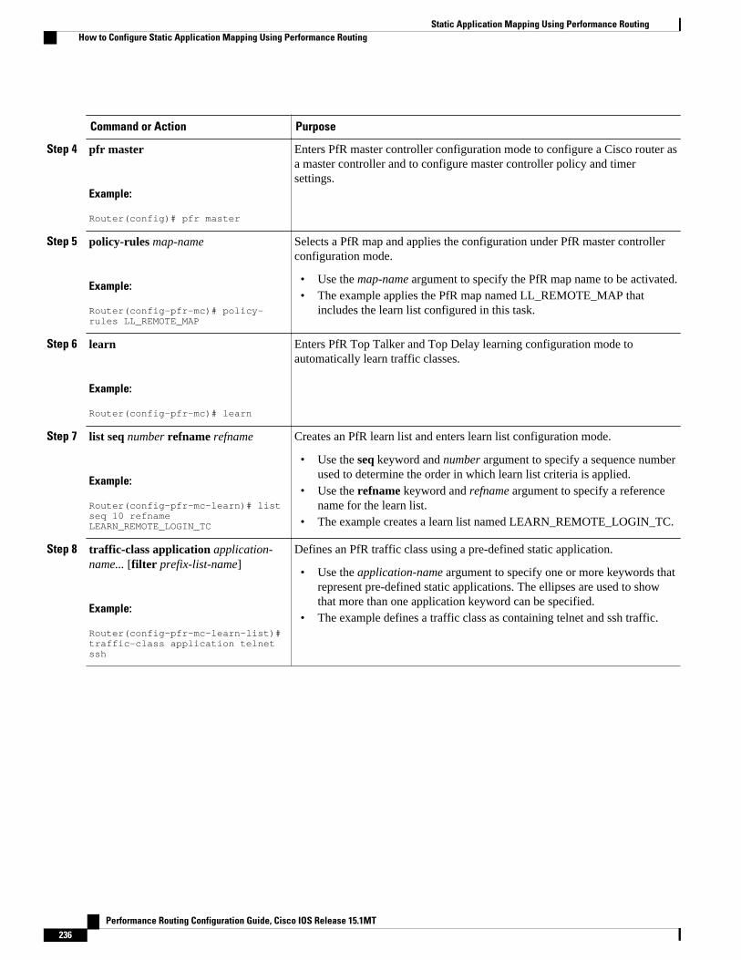
Command or Action Purpose
Step 4 pfr master
Example:
Router(config)# pfr master
Enters PfR master controller configuration mode to configure a Cisco router asa master controller and to configure master controller policy and timersettings.
Step 5 policy-rules map-name
Example:
Router(config-pfr-mc)# policy-rules LL_REMOTE_MAP
Selects a PfR map and applies the configuration under PfR master controllerconfiguration mode.
• Use the map-name argument to specify the PfR map name to be activated.• The example applies the PfR map named LL_REMOTE_MAP that
includes the learn list configured in this task.
Step 6 learn
Example:
Router(config-pfr-mc)# learn
Enters PfR Top Talker and Top Delay learning configuration mode toautomatically learn traffic classes.
Step 7 list seq number refname refname
Example:
Router(config-pfr-mc-learn)# list seq 10 refname LEARN_REMOTE_LOGIN_TC
Creates an PfR learn list and enters learn list configuration mode.
• Use the seq keyword and number argument to specify a sequence numberused to determine the order in which learn list criteria is applied.
• Use the refname keyword and refname argument to specify a referencename for the learn list.
• The example creates a learn list named LEARN_REMOTE_LOGIN_TC.
Step 8 traffic-class application application-name... [filter prefix-list-name]
Example:
Router(config-pfr-mc-learn-list)# traffic-class application telnet ssh
Defines an PfR traffic class using a pre-defined static application.
• Use the application-name argument to specify one or more keywords thatrepresent pre-defined static applications. The ellipses are used to showthat more than one application keyword can be specified.
• The example defines a traffic class as containing telnet and ssh traffic.
Static Application Mapping Using Performance Routing How to Configure Static Application Mapping Using Performance Routing
Performance Routing Configuration Guide, Cisco IOS Release 15.1MT236

Command or Action Purpose
Step 9 aggregation-type {bgp non-bgp prefix-length} prefix-mask
Example:
Router(config-pfr-mc-learn-list)# aggregation-type prefix-length 24
(Optional) Configures a master controller to aggregate learned prefixes basedon traffic flow type.
• The bgp keyword configures prefix aggregation based on entries in theBGP routing table. This keyword is used if BGP peering is enabled in thenetwork.
• The non-bgp keyword configures learned prefix aggregation based onstatic routes. Entries in the BGP routing table are ignored when thiskeyword is entered.
• The prefix-length keyword configures aggregation based on the specifiedprefix length. The range of values that can be configured for thisargument is a prefix mask from 1 to 32.
• If this command is not specified, the default aggregation is performedbased on a /24 prefix length.
• The example configures prefix length aggregation based on a /24 prefixlength.
Step 10 throughput
Example:
Router(config-pfr-mc-learn-list)# throughput
Configures the master controller to learn the top prefixes based on the highestoutbound throughput.
• When this command is enabled, the master controller will learn the topprefixes across all border routers according to the highest outboundthroughput.
• The example configures a master controller to learn the top prefixes basedon highest outbound throughput for the LEARN_REMOTE_LOGIN_TCtraffic class.
Step 11 exit
Example:
Router(config-pfr-mc-learn-list)# exit
Exits learn list configuration mode, and returns to PfR Top Talker and TopDelay learning configuration mode.
Step 12 Repeat Step 7 to Step 11 to configureadditional learn lists
--
Step 13 exit
Example:
Router(config-pfr-mc-learn)# exit
Exits PfR Top Talker and Top Delay learn configuration mode, and returns toPfR master controller configuration mode.
Step 14 Repeat Step 13 to return to globalconfiguration mode.
--
Static Application Mapping Using Performance RoutingHow to Configure Static Application Mapping Using Performance Routing
Performance Routing Configuration Guide, Cisco IOS Release 15.1MT 237

Command or Action Purpose
Step 15 pfr-map map-name sequence-number
Example:
Router(config)# pfr-map LL_REMOTE_MAP 10
Enters PfR map configuration mode to configure a PfR map.
• Only one match clause can be configured for each PfR map sequence.• The example creates a PfR map named LL_REMOTE_MAP.
Step 16 match pfr learn list refname
Example:
Router(config-oer-map)# match pfr learn list LEARN_REMOTE_LOGIN_TC
Creates a match clause entry in a PfR map to match PfR learned prefixes.
• The example defines a traffic class using the criteria defined in the PfRlearn list named LEARN_REMOTE_LOGIN_TC.
Note Only the syntax relevant to this task is used here.
Step 17 end
Example:
Router(config-oer-map)# end
(Optional) Exits OER map configuration mode and returns to privilegedEXEC mode.
Example
In this example, two learn lists are configured to identify remote login traffic and file transfer traffic. Theremote login traffic class is configured using keywords representing Telnet and Secure Shell (SSH) traffic,and the resulting prefixes are aggregated to a prefix length of 24. The file transfer traffic class is configuredusing a keyword that represents FTP and is also aggregated to a prefix length of 24. A prefix list is appliedto the file transfer traffic class to permit traffic from the 10.0.0.0/8 prefix. The master controller isconfigured to learn the top prefixes based on highest outbound throughput for the filtered traffic, and theresulting traffic classes are added to the PfR application database. PfR maps are configured to match thelearn lists and the File Transfer traffic class is activated using the policy-rules (PfR) command.
ip prefix-list INCLUDE_10_NET 10.0.0.0/8pfr master policy-rules LL_FILE_MAP learn list seq 10 refname LEARN_REMOTE_LOGIN_TC traffic-class application telnet ssh aggregation-type prefix-length 24 throughput exit list seq 20 refname LEARN_FILE_TRANSFER_TC traffic-class application ftp filter INCLUDE_10_NET aggregation-type prefix-length 24 throughput exit exit exitpfr-map LL_REMOTE_MAP 10 match pfr learn list LEARN_REMOTE_LOGIN_TC exitpfr-map LL_FILE_MAP 20 match pfr learn list LEARN_FILE_TRANSFER_TC end
Static Application Mapping Using Performance Routing How to Configure Static Application Mapping Using Performance Routing
Performance Routing Configuration Guide, Cisco IOS Release 15.1MT238

Manually Selecting Traffic Classes Using Static Application MappingPerform this task to manually select traffic classes using static application mapping. Use this task when youknow the destination prefixes and the applications that you want to select for the traffic classes. In this task,an IP prefix list is created to define the destination prefixes, and static applications are defined using thematch traffic-class application (PfR) command. Using a PfR map, each prefix is matched with eachapplication to create the traffic classes.
SUMMARY STEPS
1. enable
2. configure terminal
3. ip prefix-list list-name [seq seq-value] {deny network/length | permit network/length}
4. Repeat Step 3 for more prefix list entries, as required.
5. pfr-map map-name sequence-number
6. match traffic-class application application-name prefix-list prefix-list-name
7. end
DETAILED STEPS
Command or Action Purpose
Step 1 enable
Example:
Router> enable
Enables privileged EXEC mode.
• Enter your password if prompted.
Step 2 configure terminal
Example:
Router# configure terminal
Enters global configuration mode.
Step 3 ip prefix-list list-name [seq seq-value]{deny network/length | permit network/length}
Example:
Router(config)# ip prefix-list LIST1 permit 10.1.1.0/24
Creates a prefix list to specify destination prefix-based traffic classes.
• The example specifies a destination prefix of 10.1.1.0/24 to be used tofilter application traffic classes.
Step 4 Repeat Step 3 for more prefix list entries, asrequired.
--
Manually Selecting Traffic Classes Using Static Application MappingHow to Configure Static Application Mapping Using Performance Routing
Performance Routing Configuration Guide, Cisco IOS Release 15.1MT 239

Command or Action Purpose
Step 5 pfr-map map-name sequence-number
Example:
Router(config)# pfr-map APPLICATION_MAP 10
Enters PfR map configuration mode to configure a PfR map.
• Only one match clause can be configured for each PfR map sequence.• Permit sequences are first defined in an IP prefix list and then applied
with the match traffic-class command in Step 6.• The example creates a PfR map named APPLICATION_MAP.
Step 6 match traffic-class application application-name prefix-list prefix-list-name
Example:
Router(config-pfr-map)# traffic-class application telnet ssh prefix-list LIST1
Manually configures one or more static applications as match criteriaagainst a prefix list to create traffic classes using a PfR map.
• Use the application-name argument to specify one or more keywordsthat represent pre-defined static applications.
• The example defines traffic classes as application X with destinationprefix Y, where X is Telnet or Secure Shell and Y is a destinationaddress defined in the IP prefix list named LIST1.
Step 7 end
Example:
Router(config-pfr-map)# end
(Optional) Exits PfR map configuration mode and returns to privilegedEXEC mode.
Displaying and Resetting Traffic Class and Learn List InformationPerform this task to display traffic class and learn list information and optionally, to reset some traffic classinformation. These commands can be entered on a master controller after learn lists are configured andtraffic classes are automatically learned, or when traffic classes are manually configured using a PfR map.The commands can be entered in any order and all the commands are optional.
SUMMARY STEPS
1. enable
2. show pfr master traffic-class [access-list access-list-name| application application-name[prefix] |inside | learned[delay | inside | list list-name| throughput] | prefix prefix| prefix-list prefix-list-name][active| passive| status] [detail]
3. show pfr master learn list [list-name]
4. clear pfr master traffic-class [access-list access-list-name| application application-name[prefix]|inside | learned[delay | inside | list list-name| throughput]| prefix prefix| prefix-list prefix-list-name]
DETAILED STEPS
Step 1 enableEnables privileged EXEC mode. Enter your password if prompted.
Displaying and Resetting Traffic Class and Learn List Information How to Configure Static Application Mapping Using Performance Routing
Performance Routing Configuration Guide, Cisco IOS Release 15.1MT240

Example:
Router> enable
Step 2 show pfr master traffic-class [access-list access-list-name| application application-name[prefix] | inside |learned[delay | inside | list list-name| throughput] | prefix prefix| prefix-list prefix-list-name] [active| passive|status] [detail]This command is used to display information about traffic classes learned or manually configured under PfR learn listconfiguration mode.
Example:
Router# show pfr master traffic-classOER Prefix Statistics: Pas - Passive, Act - Active, S - Short term, L - Long term, Dly - Delay (ms), P - Percentage below threshold, Jit - Jitter (ms), MOS - Mean Opinion Score Los - Packet Loss (packets-per-million), Un - Unreachable (flows-per-million), E - Egress, I - Ingress, Bw - Bandwidth (kbps), N - Not applicable U - unknown, * - uncontrolled, + - control more specific, @ - active probe all # - Prefix monitor mode is Special, & - Blackholed Prefix % - Force Next-Hop, ^ - Prefix is denied DstPrefix Appl_ID Dscp Prot SrcPort DstPort SrcPrefix Flags State Time CurrBR CurrI/F Protocol PasSDly PasLDly PasSUn PasLUn PasSLos PasLLos EBw IBw ActSDly ActLDly ActSUn ActLUn ActSJit ActPMOS--------------------------------------------------------------------------------10.1.1.0/24 N defa N N N N # OOPOLICY 32 10.11.1.3 Gi0/0/1 BGP N N N N N N N IBwN 130 134 0 0 N N
Step 3 show pfr master learn list [list-name]This command is used to display one or all of the configured PfR learn lists. In this example, the information abouttwo learn lists is displayed.
Example:
Router# show pfr master learn listLearn-List LIST1 10 Configuration: Application: ftp Aggregation-type: bgp Learn type: thruput Policies assigned: 8 10 Stats: Application Count: 0 Application Learned: Learn-List LIST2 20 Configuration: Application: telnet Aggregation-type: prefix-length 24 Learn type: thruput Policies assigned: 5 20 Stats: Application Count: 2 Application Learned: Appl Prefix 10.1.5.0/24 telnet Appl Prefix 10.1.5.16/28 telnet
Step 4 clear pfr master traffic-class [access-list access-list-name| application application-name[prefix]| inside |learned[delay | inside | list list-name| throughput]| prefix prefix| prefix-list prefix-list-name]
Static Application Mapping Using Performance RoutingHow to Configure Static Application Mapping Using Performance Routing
Performance Routing Configuration Guide, Cisco IOS Release 15.1MT 241
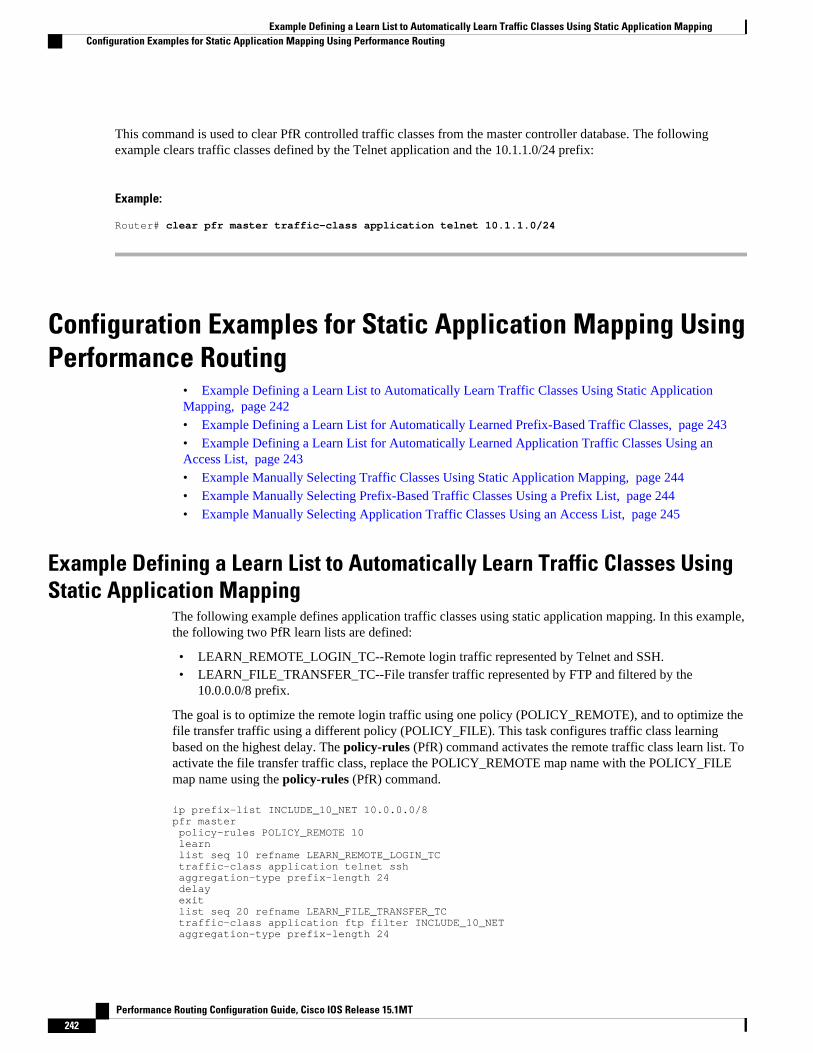
This command is used to clear PfR controlled traffic classes from the master controller database. The followingexample clears traffic classes defined by the Telnet application and the 10.1.1.0/24 prefix:
Example:
Router# clear pfr master traffic-class application telnet 10.1.1.0/24
Configuration Examples for Static Application Mapping UsingPerformance Routing
• Example Defining a Learn List to Automatically Learn Traffic Classes Using Static ApplicationMapping, page 242• Example Defining a Learn List for Automatically Learned Prefix-Based Traffic Classes, page 243• Example Defining a Learn List for Automatically Learned Application Traffic Classes Using anAccess List, page 243• Example Manually Selecting Traffic Classes Using Static Application Mapping, page 244• Example Manually Selecting Prefix-Based Traffic Classes Using a Prefix List, page 244• Example Manually Selecting Application Traffic Classes Using an Access List, page 245
Example Defining a Learn List to Automatically Learn Traffic Classes UsingStatic Application Mapping
The following example defines application traffic classes using static application mapping. In this example,the following two PfR learn lists are defined:
• LEARN_REMOTE_LOGIN_TC--Remote login traffic represented by Telnet and SSH.• LEARN_FILE_TRANSFER_TC--File transfer traffic represented by FTP and filtered by the
10.0.0.0/8 prefix.
The goal is to optimize the remote login traffic using one policy (POLICY_REMOTE), and to optimize thefile transfer traffic using a different policy (POLICY_FILE). This task configures traffic class learningbased on the highest delay. The policy-rules (PfR) command activates the remote traffic class learn list. Toactivate the file transfer traffic class, replace the POLICY_REMOTE map name with the POLICY_FILEmap name using the policy-rules (PfR) command.
ip prefix-list INCLUDE_10_NET 10.0.0.0/8pfr master policy-rules POLICY_REMOTE 10 learn list seq 10 refname LEARN_REMOTE_LOGIN_TC traffic-class application telnet ssh aggregation-type prefix-length 24 delay exit list seq 20 refname LEARN_FILE_TRANSFER_TC traffic-class application ftp filter INCLUDE_10_NET aggregation-type prefix-length 24
Example Defining a Learn List to Automatically Learn Traffic Classes Using Static Application Mapping Configuration Examples for Static Application Mapping Using Performance Routing
Performance Routing Configuration Guide, Cisco IOS Release 15.1MT242

delay exit exitpfr-map POLICY_REMOTE 10 match pfr learn list LEARN_REMOTE_LOGIN_TC exitpfr-map POLICY_FILE 20 match pfr learn list LEARN_FILE_TRANSFER_TC end
Example Defining a Learn List for Automatically Learned Prefix-BasedTraffic Classes
The following example configured on the master controller, defines a learn list that will contain trafficclasses that are automatically learned based only on a prefix list. In this example, there are three branchoffices and the goal is to optimize all the traffic going to branch offices A and B using one policy (Policy1),and to optimize traffic going to branch office C using a different policy (Policy2).
Branch A is defined as any prefix that matches 10.1.0.0./16, Branch B is defined as any prefix that matches10.2.0.0./16, and Branch C is defined as any prefix that matches 10.3.0.0./16.
This task configures prefix learning based on the highest outbound throughput. The policy-rules (PfR)command activates the traffic class learn list configured for branch offices A and B.
ip prefix-list BRANCH_A_B permit seq 10 10.1.0.0/16ip prefix-list BRANCH_A_B permit seq 20 10.2.0.0/16ip prefix-list BRANCH_C permit seq 30 10.3.0.0/16pfr master policy-rules POLICY1 learn list seq 10 refname LEARN_BRANCH_A_B traffic-class prefix-list BRANCH_A_B throughput exit list seq 20 refname LEARN_BRANCH_C traffic-class prefix-list BRANCH_C throughput exit exit exitpfr-map POLICY1 10 match pfr learn list LEARN_BRANCH_A_B exitpfr-map POLICY2 10 match pfr learn list LEARN_BRANCH_C end
Example Defining a Learn List for Automatically Learned Application TrafficClasses Using an Access List
The following example creates an access list that defines custom application traffic classes. In this example,the custom application consists of four criteria:
• Any TCP traffic on destination port 500• Any TCP traffic on ports in the range from 700 to 750• Any UDP traffic on source port 400• Any IP packet marked with a DSCP bit of ef
Example Defining a Learn List for Automatically Learned Prefix-Based Traffic ClassesConfiguration Examples for Static Application Mapping Using Performance Routing
Performance Routing Configuration Guide, Cisco IOS Release 15.1MT 243

The goal is to optimize the custom application traffic using a learn list that is referenced in a PfR policynamed POLICY_CUSTOM_APP. This task configures traffic class learning based on the highest outboundthroughput. The policy-rules (PfR) command activates the custom application traffic class learn list.
ip access-list extended USER_DEFINED_TC permit tcp any any 500 permit tcp any any range 700 750 permit udp any eq 400 any permit ip any any dscp ef exitpfr master policy-rules POLICY_CUSTOM_APP learn list seq 10 refname CUSTOM_APPLICATION_TC traffic-class access-list USER_DEFINED_TC aggregation-type prefix-length 24 throughput exit exit exitpfr-map POLICY_CUSTOM_APP 10 match pfr learn list CUSTOM_APPLICATION_TC end
Example Manually Selecting Traffic Classes Using Static ApplicationMapping
The following example starting in global configuration mode, configures a PfR map to include applicationtraffic predefined as telnet or Secure Shell and destined to prefixes in the 10.1.1.0/24 network, 10.1.2.0/24network, and 172.16.1.0/24 network.
ip prefix-list LIST1 permit 10.1.1.0/24ip prefix-list LIST1 permit 10.1.2.0/24ip prefix-list LIST1 permit 172.16.1.0/24pfr-map PREFIXES 10 match traffic-class application telnet ssh prefix-list LIST1 end
Example Manually Selecting Prefix-Based Traffic Classes Using a PrefixList
The following example configured on the master controller, manually selects traffic classes based only ondestination prefixes. Use this task when you know the destination prefixes that you want to select for thetraffic classes. An IP prefix list is created to define the destination prefixes and using a PfR map, the trafficclasses are profiled.
ip prefix-list PREFIX_TC permit 10.1.1.0/24ip prefix-list PREFIX_TC permit 10.1.2.0/24ip prefix-list PREFIX_TC permit 172.16.1.0/24pfr-map PREFIX_MAP 10 match traffic-class prefix-list PREFIX_TC end
Example Manually Selecting Traffic Classes Using Static Application Mapping Configuration Examples for Static Application Mapping Using Performance Routing
Performance Routing Configuration Guide, Cisco IOS Release 15.1MT244

Example Manually Selecting Application Traffic Classes Using an AccessList
The following example configured on the master controller, manually selects traffic classes using an accesslist. Each access list entry is a traffic class that must include a destination prefix and may include otheroptional parameters.
ip access-list extended ACCESS_TC permit tcp any 10.1.1.0 0.0.0.255 eq 500 permit tcp any 172.17.1.0 0.0.255.255 eq 500 permit tcp any 172.17.1.0 0.0.255.255 range 700 750 permit tcp 192.168.1.1 0.0.0.0 10.1.2.0 0.0.0.255 eq 800any any dscp ef exitpfr-map ACCESS_MAP 10 match traffic-class access-list ACCESS_TC
Where To Go NextFor information about other Performance Routing features or general conceptual material, see thedocuments in the “Related Documents” section.
Additional ReferencesRelated Documents
Related Topic Document Title
Cisco IOS commands Cisco IOS Master Commands List, All Releases
Cisco PfR commands: complete command syntax,command mode, command history, defaults, usageguidelines and examples
Cisco IOS Performance Routing CommandReference
Basic PfR configuration "Configuring Basic Performance Routing" module
Concepts required to understand the PerformanceRouting operational phases
"Understanding Performance Routing" module
Advanced PfR configuration "Configuring Advanced Performance Routing"module
IP SLAs overview IP SLAs Configuration Guide
Example Manually Selecting Application Traffic Classes Using an Access ListWhere To Go Next
Performance Routing Configuration Guide, Cisco IOS Release 15.1MT 245

Technical Assistance
Description Link
The Cisco Support and Documentation websiteprovides online resources to downloaddocumentation, software, and tools. Use theseresources to install and configure the software andto troubleshoot and resolve technical issues withCisco products and technologies. Access to mosttools on the Cisco Support and Documentationwebsite requires a Cisco.com user ID andpassword.
http://www.cisco.com/cisco/web/support/index.html
Feature Information for Static Application Mapping UsingPerformance Routing
The following table provides release information about the feature or features described in this module.This table lists only the software release that introduced support for a given feature in a given softwarerelease train. Unless noted otherwise, subsequent releases of that software release train also support thatfeature.
Use Cisco Feature Navigator to find information about platform support and Cisco software image support.To access Cisco Feature Navigator, go to www.cisco.com/go/cfn. An account on Cisco.com is not required.
Static Application Mapping Using Performance Routing Feature Information for Static Application Mapping Using Performance Routing
Performance Routing Configuration Guide, Cisco IOS Release 15.1MT246

Table 15 Feature Information for Static Application Mapping Using Performance Routing
Feature Name Releases Feature Configuration Information
OER - Application AwareRouting with Static ApplicationMapping
12.4(15)T The OER - Application AwareRouting with Static ApplicationMapping feature introduces theability to configure standardapplications using just onekeyword. This feature alsointroduces a learn listconfiguration mode that allowsPerformance Routing (PfR)policies to be applied to trafficclasses profiled in a learn list.Different policies can be appliedto each learn list. New traffic-class and match traffic-classcommands are introduced tosimplify the configuration oftraffic classes that PfR canautomatically learn, or that can bemanually configured.
The following commands wereintroduced or modified by thisfeature: clear pfr master traffic-class, count (PfR), delay(PfR),list (PfR), match traffic-class access-list (PfR), matchtraffic-class application (PfR),match traffic-class prefix-list(PfR), show pfr border definedapplication, show pfr masterdefined application, show pfrmaster learn list, show pfrmaster traffic-class, throughput(PfR), traffic-class access-list(PfR), traffic-class application(PfR), traffic-class prefix-list(PfR).
Cisco and the Cisco Logo are trademarks of Cisco Systems, Inc. and/or its affiliates in the U.S. and othercountries. A listing of Cisco's trademarks can be found at www.cisco.com/go/trademarks. Third partytrademarks mentioned are the property of their respective owners. The use of the word partner does notimply a partnership relationship between Cisco and any other company. (1005R)
Any Internet Protocol (IP) addresses and phone numbers used in this document are not intended to beactual addresses and phone numbers. Any examples, command display output, network topology diagrams,
Static Application Mapping Using Performance Routing
Performance Routing Configuration Guide, Cisco IOS Release 15.1MT 247

and other figures included in the document are shown for illustrative purposes only. Any use of actual IPaddresses or phone numbers in illustrative content is unintentional and coincidental.
Static Application Mapping Using Performance Routing
Performance Routing Configuration Guide, Cisco IOS Release 15.1MT248

Performance Routing Traceroute Reporting
Performance Routing (PfR) support for traceroute reporting allows you to monitor prefix performance ona hop-by-hop basis. Delay, loss, and reachability measurements are gathered for each hop from the probesource (border router) to the target prefix.
• Finding Feature Information, page 249• Information About Performance Routing Traceroute Reporting, page 249• How to Configure Performance Routing Traceroute Reporting, page 250• Configuration Examples for Performance Routing Traceroute Reporting, page 253• Where to Go Next, page 254• Additional References, page 254• Feature Information for Performance Routing Traceroute Reporting, page 255
Finding Feature InformationYour software release may not support all the features documented in this module. For the latest featureinformation and caveats, see the release notes for your platform and software release. To find informationabout the features documented in this module, and to see a list of the releases in which each feature issupported, see the Feature Information Table at the end of this document.
Use Cisco Feature Navigator to find information about platform support and Cisco software image support.To access Cisco Feature Navigator, go to www.cisco.com/go/cfn. An account on Cisco.com is not required.
Information About Performance Routing Traceroute Reporting• PfR Logging and Reporting, page 249
• PfR Troubleshooting Using Traceroute Reporting, page 250
PfR Logging and ReportingCisco IOS PfR supports standard syslog functions. The notice level of syslog is enabled by default. Systemlogging is enabled and configured in Cisco IOS software under global configuration mode. Thelogging(PfR) command in PfR master controller or PfR border router configuration mode is used only toenable or disable system logging under PfR. PfR system logging supports the following message types:
• Error Messages--These messages indicate PfR operational failures and communication problems thatcan impact normal PfR operation.
Performance Routing Configuration Guide, Cisco IOS Release 15.1MT 249

• Debug Messages--These messages are used to monitor detailed PfR operations to diagnose operationalor software problems.
• Notification Messages--These messages indicate that PfR is performing a normal operation.• Warning Messages--These messages indicate that PfR is functioning properly but an event outside of
PfR may be impacting normal PfR operation.
To modify system, terminal, destination, and other system global logging parameters, use the loggingcommands in global configuration mode. For more information about global system logging configuration,see to the “Troubleshooting, Logging, and Fault Management” section of the Cisco IOS NetworkManagement Configuration Guide .
PfR Troubleshooting Using Traceroute ReportingAlthough PfR provides the ability to diagnose issues using syslog and debug command-line interface (CLI)commands, support for traceroute reporting was introduced in the OER Support for Cost-BasedOptimization and Traceoute Reporting feature. Using traceroute reporting, PfR reports traffic classperformance by determining the delay on a hop-by-hop basis using traceroute probes.
Prior to traceroute reporting there was no method for measuring the delay per hop for situations such as anunexpected round trip delay value being reported for a traffic class on an exit link. PfR uses UDPtraceroutes to collect per-hop delay statistics. A traceroute is defined as tracing the route to the device withthe given IP address or the hostname and is useful in detecting the location of a problem that exists in thepath to the device. Although traditional UDP-based traceroutes are used by default, PfR can be configuredto send TCP SYN packets to specific ports that may be permitted through a firewall.
Traceroute reporting is configured on the master controller. Traceroute probes are sourced from the borderrouter exit. This feature allows you to monitor traffic class performance on a hop-by-hop basis. Whentraceroute reporting is enabled, the autonomous system number, the IP address, and delay measurementsare gathered for each hop from the probe source to the target prefix. By default, traceroute probes are sentonly when the traffic class goes OOP. TCP-based traceroutes can be configured manually and the timeinterval between traceroute probes can be modified. By default, per-hop delay reporting is not enabled.
Traceroute probes are configured using the following methods:
• Periodic--A traceroute probe is triggered for each new probe cycle. The probe is sourced from thecurrent exit of the traffic class when the option to probe only one exit is selected. If the option to probeall exits is selected, the traceroute probe is sourced from all available exits.
• Policy based--A traceroute probe is triggered automatically when a traffic class goes into an out-of-policy state. Traceroute reporting can be enabled for all traffic classes specified in the match clause ofan PfR map. Policy based traceroute reporting stops when the traffic class returns to an in-policy state.
• On demand--A trace route probe can be triggered on an on demand basis when periodic traceroutereporting is not required, or the per-hop statistics are not required for all paths. Using optionalkeywords and arguments of the show pfr master prefix command, you can start traceroute reportingfor a specific traffic class on a specific path, or all paths.
How to Configure Performance Routing Traceroute Reporting• Configuring PfR Traceroute Reporting, page 251
PfR Troubleshooting Using Traceroute Reporting How to Configure Performance Routing Traceroute Reporting
Performance Routing Configuration Guide, Cisco IOS Release 15.1MT250

Configuring PfR Traceroute ReportingPerform this task at the master controller to configure traceroute reporting. When using a PfR active probethere are situations when a host address does not respond to the PfR probe message. The reason for noresponse to the probe message may be due to a firewall or other network issue but PfR assumes the hostaddress to be unreachable and releases control of the prefix. Prior to traceroute reporting there was nomethod for measuring the delay per hop for situations such as an unexpected round trip delay value beingreported for a traffic class on an exit link. The solution for both the non-responding target address and thelack of per-hop delay information involves using UDP, and optionally TCP, traceroutes. Traceroutereporting is configured on a master controller, but the traceroute probes are sourced from the border routerexits.
In this task, the three methods of configuring traceroute probes are used. Periodic and policy-basedtraceroute reporting are configured with the set traceroute reporting (PfR) command using a PfR map.On-demand traceroute probes are triggered by entering the show pfr master prefix command with certainparameters. This task also shows to modify the time interval between traceroute probes using thetraceroute probe-delay (PfR) command.
When traceroute reporting is enabled, the default time interval between traceroute probes is 1000milliseconds.
SUMMARY STEPS
1. enable
2. configure terminal
3. pfr master
4. traceroute probe-delay milliseconds
5. exit
6. pfr-map map-name sequence-number
7. match pfr learn {delay | throughput}
8. set traceroute reporting [policy {delay | loss | unreachable}]
9. end
10. show pfr master prefix [detail | learned [delay | throughput] | prefix [detail | policy | traceroute[exit-id | border-address | current] [now]]]
DETAILED STEPS
Command or Action Purpose
Step 1 enable
Example:
Router> enable
Enables privileged EXEC mode.
• Enter your password if prompted.
Configuring PfR Traceroute ReportingHow to Configure Performance Routing Traceroute Reporting
Performance Routing Configuration Guide, Cisco IOS Release 15.1MT 251

Command or Action Purpose
Step 2 configure terminal
Example:
Router# configure terminal
Enters global configuration mode.
Step 3 pfr master
Example:
Router(config)# pfr master
Enters PfR master controller configuration mode to configure a router as amaster controller and to configure global operations and policies.
Step 4 traceroute probe-delay milliseconds
Example:
Router(config-pfr-mc)# traceroute probe-delay 500
Sets the time interval between traceroute probe cycles.
• The default time interval between traceroute probes is 1000milliseconds.
• The example sets the probe interval to a 500 milliseconds.
Step 5 exit
Example:
Router(config-pfr-mc)# exit
Exits PfR master controller configuration mode, and returns to globalconfiguration mode.
Step 6 pfr-map map-name sequence-number
Example:
Router(config)# pfr-map TRACEROUTE 10
Enters PfR map configuration mode to configure a PfR map to applypolicies to selected IP prefixes.
• Only one match clause can be configured for each PfR map sequence.• The example creates a PfR map named TRACEROUTE.
Step 7 match pfr learn {delay | throughput}
Example:
Router(config-pfr-map)# match pfr learn delay
Creates a match clause entry in a PfR map to match learned prefixes.
• Can be configured to learn prefixes based on highest delay or highestoutbound throughput.
• Only a single match clause can be configured for each PfR mapsequence.
• The example creates a match clause entry that matches traffic learnedbased on highest delay.
Performance Routing Traceroute Reporting How to Configure Performance Routing Traceroute Reporting
Performance Routing Configuration Guide, Cisco IOS Release 15.1MT252

Command or Action Purpose
Step 8 set traceroute reporting [policy {delay |loss | unreachable}]
Example:
Router(config-pfr-map)# set traceroute reporting
Enables traceroute reporting.
• Monitored prefixes must be included in a PfR map. These can belearned or manually selected prefixes.
• Entering this command with no keywords enables continuousmonitoring.
• Entering this command with the policy keyword enables policy-basedtrace route reporting.
Step 9 end
Example:
Router(config-pfr-map)# end
Exits PfR master controller configuration mode, and returns to privilegedEXEC mode.
Step 10 show pfr master prefix [detail | learned[delay | throughput] | prefix [detail |policy | traceroute [exit-id | border-address| current] [now]]]
Example:
Router# show pfr master prefix 10.5.5.5 traceroute now
Displays the status of monitored prefixes.
• An on-demand traceroute probe is initiated by entering the currentand now keywords.
• The current keyword displays the results of the most recent tracerouteprobe for the current exit.
• Traceroute probe results can be displayed for the specified borderrouter exit by entering the exit-id or border-addressargument.
• The example initiates an on-demand traceroute probe for the 10.5.5.55prefix.
Configuration Examples for Performance Routing TracerouteReporting
• Example Configuring PfR Traceroute Reporting, page 253
Example Configuring PfR Traceroute ReportingThe following example, starting in global configuration mode, configures continuous traceroute reportingfor traffic classes learned on the basis of delay:
Router(config)# pfr master Router(config-pfr-mc)# traceroute probe-delay 10000 Router(config-pfr-mc)# exit Router(config)# pfr-map TRACE 10 Router(config-pfr-map)# match pfr learn delay Router(config-pfr-map)# set traceroute reporting Router(config-pfr-map)# end
Example Configuring PfR Traceroute ReportingConfiguration Examples for Performance Routing Traceroute Reporting
Performance Routing Configuration Guide, Cisco IOS Release 15.1MT 253

The following example, starting in privileged EXEC mode, initiates an on-demand traceroute probe for the10.5.5.5 prefix:
Router# show pfr master prefix 10.5.5.55 traceroute current now Path for Prefix: 10.5.5.0/24 Target: 10.5.5.5 Exit ID: 2, Border: 10.1.1.3 External Interface: Et1/0 Status: DONE, How Recent: 00:00:08 minutes oldHop Host Time(ms) BGP 1 10.1.4.2 8 0 2 10.1.3.2 8 300 3 10.5.5.5 20 50
Where to Go NextFor information about other Performance Routing features or general conceptual material, see thedocuments in the “Related Documents” section.
Additional ReferencesRelated Documents
Related Topic Document Title
Cisco IOS commands Cisco IOS Master Commands List, All Releases
Cisco PfR commands: complete command syntax,command mode, command history, defaults, usageguidelines and examples
Cisco IOS Performance Routing CommandReference
Basic PfR configuration "Configuring Basic Performance Routing" module
Concepts required to understand the PerformanceRouting operational phases
"Understanding Performance Routing" module
Advanced PfR configuration "Configuring Advanced Performance Routing"module
IP SLAs overview IP SLAs Configuration Guide
Performance Routing Traceroute Reporting Where to Go Next
Performance Routing Configuration Guide, Cisco IOS Release 15.1MT254

Technical Assistance
Description Link
The Cisco Support and Documentation websiteprovides online resources to downloaddocumentation, software, and tools. Use theseresources to install and configure the software andto troubleshoot and resolve technical issues withCisco products and technologies. Access to mosttools on the Cisco Support and Documentationwebsite requires a Cisco.com user ID andpassword.
http://www.cisco.com/cisco/web/support/index.html
Feature Information for Performance Routing TracerouteReporting
The following table provides release information about the feature or features described in this module.This table lists only the software release that introduced support for a given feature in a given softwarerelease train. Unless noted otherwise, subsequent releases of that software release train also support thatfeature.
Use Cisco Feature Navigator to find information about platform support and Cisco software image support.To access Cisco Feature Navigator, go to www.cisco.com/go/cfn. An account on Cisco.com is not required.
Table 16 Feature Information for Performance Routing Traceroute Reporting
Feature Name Releases Feature Information
OER Support for Cost-BasedOptimization and TracerouteReporting
12.3(14)T, 12.2(33)SRB Performance Routing support fortraceroute reporting allows you tomonitor prefix performance on ahop-by-hop basis. Delay, loss,and reachability measurementsare gathered for each hop fromthe probe source (border router)to the target prefix.
The following commands wereintroduced or modified by thisfeature: set traceroute reporting(PfR), traceroute probe-delay(PfR), and show pfr masterprefix.
Cisco and the Cisco Logo are trademarks of Cisco Systems, Inc. and/or its affiliates in the U.S. and othercountries. A listing of Cisco's trademarks can be found at www.cisco.com/go/trademarks. Third party
Performance Routing Traceroute ReportingFeature Information for Performance Routing Traceroute Reporting
Performance Routing Configuration Guide, Cisco IOS Release 15.1MT 255

trademarks mentioned are the property of their respective owners. The use of the word partner does notimply a partnership relationship between Cisco and any other company. (1005R)
Any Internet Protocol (IP) addresses and phone numbers used in this document are not intended to beactual addresses and phone numbers. Any examples, command display output, network topology diagrams,and other figures included in the document are shown for illustrative purposes only. Any use of actual IPaddresses or phone numbers in illustrative content is unintentional and coincidental.
Performance Routing Traceroute Reporting
Performance Routing Configuration Guide, Cisco IOS Release 15.1MT256

PfR Voice Traffic Optimization Using ActiveProbes
This module documents a Performance Routing (PfR) solution that supports outbound optimization ofvoice traffic based on the voice metrics, jitter and Mean Opinion Score (MOS). Jitter and MOS areimportant quantitative quality metrics for voice traffic and these voice metrics are measured using PfRactive probes.
PfR provides automatic route optimization and load distribution for multiple connections betweennetworks. PfR is an integrated Cisco IOS solution that allows you to monitor IP traffic flows and thendefine policies and rules based on prefix performance, link load distribution, link bandwidth monetarycost, and traffic type. PfR provides active and passive monitoring systems, dynamic failure detection, andautomatic path correction. Deploying PfR enables intelligent load distribution and optimal route selectionin an enterprise network.
• Finding Feature Information, page 257• Prerequisites for PfR Voice Traffic Optimization Using Active Probes, page 257• Information About PfR Voice Traffic Optimization Using Active Probes, page 258• How to Configure PfR Voice Traffic Optimization Using Active Probes, page 261• Configuration Examples for PfR Voice Traffic Optimization Using Active Probes, page 270• Where to Go Next, page 273• Additional References, page 273• Feature Information for PfR Voice Traffic Optimization Using Active Probes, page 274
Finding Feature InformationYour software release may not support all the features documented in this module. For the latest featureinformation and caveats, see the release notes for your platform and software release. To find informationabout the features documented in this module, and to see a list of the releases in which each feature issupported, see the Feature Information Table at the end of this document.
Use Cisco Feature Navigator to find information about platform support and Cisco software image support.To access Cisco Feature Navigator, go to www.cisco.com/go/cfn. An account on Cisco.com is not required.
Prerequisites for PfR Voice Traffic Optimization Using ActiveProbes
Before implementing PfR optimization for voice traffic, you need to understand an overview of how PfRworks and how to set up PfR network components. See the Understanding Performance Routing,
Performance Routing Configuration Guide, Cisco IOS Release 15.1MT 257

Configuring Basic Performance Routing, and Configuring Advanced Performance Routing modules formore details.
Information About PfR Voice Traffic Optimization UsingActive Probes
• Voice Quality on IP Networks, page 258
• Probes Used by PfR, page 259
• PfR Voice Traffic Optimization Using Active Probes, page 259
• PfR Voice Performance Metrics, page 260
• PfR Active Probe Forced Target Assignment, page 260
Voice Quality on IP NetworksVoice packets traveling through an IP network are no different from data packets. In the plain old telephonesystem (POTS), voice traffic travels over circuit-switched networks with predetermined paths and eachphone call is given a dedicated connection for the duration of the call. Voice traffic using POTS has noresource contention issues, but voice traffic over an IP network has to contend with factors such as delay,jitter, and packet loss, which can affect the quality of the phone call.
Delay
Delay (also referred as latency) for voice packets is defined as the delay between when the packet was sentfrom the source device and when it arrived at a destination device. Delay can be measured as one-waydelay or round-trip delay. The largest contributor to latency is caused by network transmission delay.Round-trip delay affects the dynamics of conversation and is used in Mean Opinion Score (MOS)calculations. One-way delay is used for diagnosing network problems. A caller may notice a delay of 200milliseconds and try to speak just as the other person is replying because of packet delay. The telephoneindustry standard specified in ITU-T G.114 recommends the maximum desired one-way delay be no morethan 150 milliseconds. Beyond a one-way delay of 150 milliseconds, voice quality is affected. With around-trip delay of 300 milliseconds or more, users may experience annoying talk-over effects.
Jitter
Jitter means interpacket delay variance. When multiple packets are sent consecutively from source todestination, for example, 10 ms apart, and if the network is behaving ideally, the destination should bereceiving them 10 ms apart. But if there are delays in the network (like queuing, arriving through alternateroutes, and so on) the arrival delay between packets might be greater than or less than 10 ms. Using thisexample, a positive jitter value indicates that the packets arrived more than 10 ms apart. If the packetsarrive 12 ms apart, then positive jitter is 2 ms; if the packets arrive 8 ms apart, then negative jitter is 2 ms.For delay-sensitive networks like VoIP, positive jitter values are undesirable, and a jitter value of 0 is ideal.
Packet Loss
Packet loss can occur due an interface failing, a packet being routed to the wrong destination, or congestionin the network. Packet loss for voice traffic leads to the degradation of service in which a caller hears thevoice sound with breaks. Although average packet loss is low, voice quality may be affected by a shortseries of lost packets.
Voice Quality on IP Networks Information About PfR Voice Traffic Optimization Using Active Probes
Performance Routing Configuration Guide, Cisco IOS Release 15.1MT258

Mean Opinion Score (MOS)
With all the factors affecting voice quality, many people ask how voice quality can be measured. Standardsbodies like the ITU have derived two important recommendations: P.800 (MOS) and P.861 (PerceptualSpeech Quality Measurement [PSQM]). P.800 is concerned with defining a method to derive a MeanOpinion Score of voice quality. MOS scores range between 1 representing the worst voice quality, and 5representing the best voice quality. A MOS of 4 is considered “toll-quality” voice.
Probes Used by PfRPfR uses some of the IP SLA probes to help gather the data PfR requires to make its decisions.
Cisco IOS IP SLAs
Cisco IOS IP SLAs are an embedded feature set in Cisco IOS software and they allow you to analyze IPservice levels for IP applications and services, to increase productivity, to lower operational costs, and toreduce occurrences of network congestion or outages. IP SLAs use active traffic monitoring--the generationof traffic in a continuous, reliable, and predictable manner--for measuring network performance. Theaccuracy of measured data is enhanced by enabling the IP SLAs Responder, available in Cisco routers, onthe destination device. For more details about IP SLAs, see the Cisco IOS IP SLAs Configuration Guide .
Active Probe Types Used by PfR
The following types of active probes can be configured:
ICMP Echo--A ping is sent to the target address. PfR uses ICMP Echo probes, by default, when an activeprobe is automatically generated. Configuring an ICMP echo probe does not require knowledgeablecooperation from the target device. However, repeated probing could trigger an Intrusion Detection System(IDS) alarm in the target network. If an IDS is configured in a target network that is not under your control,we recommend that you notify the administrator of this target network.
Jitter--A jitter probe is sent to the target address. A target port number must be specified. A remoteresponder must be enabled on the target device, regardless of the configured port number.
TCP Connection--A TCP connection probe is sent to the target address. A target port number must bespecified. A remote responder must be enabled if TCP messages are configured to use a port number otherthan TCP port number 23, which is well-known.
UDP Echo--A UDP echo probe is sent to the target address. A target port number must be specified. Aremote responder must be enabled on the target device, regardless of which port number is configured.
Probe Frequency
The frequency of an active probe used by PfR is set by default to 60 seconds, but the frequency can beincreased for each policy by configuring a lower time-interval between two probes. Increased probefrequency can reduce the response time and provide a better approximation of the MOS-low countpercentage.
PfR Voice Traffic Optimization Using Active ProbesConfiguring PfR to optimize voice traffic using active probes involves several decisions and subsequentbranching tasks. The first step is to identify the traffic to be optimized and decide whether to use a prefixlist or an access list. Use a prefix list to identify all traffic, including voice traffic, with a specific set ofdestination prefixes. Use an access list to identify only voice traffic with a specific destination prefix andcarried over a specific protocol.
Probes Used by PfRInformation About PfR Voice Traffic Optimization Using Active Probes
Performance Routing Configuration Guide, Cisco IOS Release 15.1MT 259

The second step in optimizing voice traffic is to configure active probing using the active-probe or setactive-probe command to specify the type of active probe to be used. PfR also provides the ability to set aforced target assignment for the active probe.
The final step in optimizing voice traffic is to configure a PfR policy to set the performance metrics thatyou want PfR to apply to the identified traffic.
PfR Voice Performance MetricsPfR voice traffic optimization provides support for outbound optimization of voice traffic on the basis ofthe voice performance metrics, delay, packet loss, jitter, and MOS. Delay, packet loss, jitter and MOS areimportant quantitative quality metrics for voice traffic, and these voice metrics are measured using PfRactive probes. The IP SLA jitter probe is integrated with PfR to measure jitter (source to destination) andthe MOS score in addition to measuring delay and packet loss. The jitter probe requires a responder on theremote side just like the UDP Echo probe. Integration of the IP SLA jitter probe type in PfR enhances theability of PfR to optimize voice traffic. PfR policies can be configured to set the threshold and priorityvalues for the voice performance metrics: delay, packet loss, jitter, and MOS.
Configuring a PfR policy to measure jitter involves configuring only the threshold value and not relativechanges (used by other PfR features) because for voice traffic, relative jitter changes have no meaning. Forexample, jitter changes from 5 milliseconds to 25 milliseconds are just as bad in terms of voice quality asjitter changes from 15 milliseconds to 25 milliseconds. If the short-term average (measuring the last 5probes) jitter is higher than the jitter threshold, the prefix is considered out-of-policy due to jitter. PfR thenprobes all exits, and the exit with the least jitter is selected as the best exit.
MOS policy works in a different way. There is no meaning to average MOS values, but there is meaning tothe number of times that the MOS value is below the MOS threshold. For example, if the MOS threshold isset to 3.85 and if 3 out of 10 MOS measurements are below the 3.85 MOS threshold, the MOS-low-count is30 percent. In the output of the show commands the field, ActPMOS, shows the number of activelymonitored MOS packets with a percentage below threshold. If some of the MOS measurements are onlyslightly below the threshold, with percentage rounding, an ActPMOS value of zero may be displayed.When PfR runs a policy configured to measure MOS, both the MOS threshold value and the MOS-low-count percentage are considered. A prefix is considered out-of-policy if the short term (average over thelast 5 probes) MOS-low-count percentage is greater than the configured MOS-low-count percentage. PfRthen probes all exits, and the exit with the highest MOS value is selected as the best exit.
PfR Active Probe Forced Target AssignmentIn earlier releases of the OER technology, the PfR active probe target is assigned to the longest matchedprefix. There are some scenarios where you may want to use a target that does not match the destination
PfR Voice Performance Metrics Information About PfR Voice Traffic Optimization Using Active Probes
Performance Routing Configuration Guide, Cisco IOS Release 15.1MT260

prefix. The example in the figure below explains a scenario in which configuring a PfR forced targetassignment is more appropriate than using the longest match prefix.
Figure 18 PfR Forced Target Assignment Scenario
246276Remote Site
10.20.21.0/24
Edge Router Network10.20.22.0/31Forced Target10.20.22.1
10.20.20.0/24
In the figure above we want to probe IP address 10.20.22.1 (at the edge of the network) for either network10.20.21.0/24 or 10.20.22.0/24. Jitter is less likely to be introduced within the network so probing the edgeof the network gives a measurement that is close to probing the final destination.
Forced target assignment allows you to assign a target to a group of prefixes or an application, even if theyare not the longest match prefixes. Assigning a target can determine the true delay to the edge of a networkrather than delay to an end host.
How to Configure PfR Voice Traffic Optimization Using ActiveProbes
Perform one of the first two optional tasks, depending on whether you want to use a prefix list or an accesslist to identify the traffic to be optimized. The third task can be used with traffic identified using an accesslist, and it also demonstrates how to use a forced target assignment. For an example configuration that canbe used with traffic identified using a prefix list, see the “Example: Optimizing Traffic (Including VoiceTraffic) Using Active Probes” section.
• Identifying Traffic for PfR Using a Prefix List, page 261
• Identifying Voice Traffic to Optimize Using an Access List, page 262
• Configuring PfR Voice Probes with a Target Assignment, page 264
Identifying Traffic for PfR Using a Prefix ListBefore traffic can be measured using PfR, it must be identified. Perform this task to use a prefix list toidentify the traffic that PfR will probe.
Identifying Traffic for PfR Using a Prefix ListHow to Configure PfR Voice Traffic Optimization Using Active Probes
Performance Routing Configuration Guide, Cisco IOS Release 15.1MT 261

SUMMARY STEPS
1. enable
2. configure terminal
3. ip prefix-list list-name [seq seq-value] {deny network / length| permit network / length}
4. exit
DETAILED STEPS
Command or Action Purpose
Step 1 enable
Example:
Router> enable
Enables privileged EXEC mode.
• Enter your password if prompted.
Step 2 configure terminal
Example:
Router# configure terminal
Enters global configuration mode.
Step 3 ip prefix-list list-name [seq seq-value]{deny network / length| permitnetwork / length}
Example:
Router(config)# ip prefix-list TRAFFIC_PFX_LIST seq 10 permit 10.20.21.0/24
Creates an IP prefix list.
• IP prefix lists are used to manually select prefixes for monitoring by the PfRmaster controller.
• A master controller can monitor and control an exact prefix (/32), a specificprefix length, or a specific prefix length and any prefix that falls under theprefix length (for example, a /24 under a /16).
• A prefix range can also be selected using the le keyword with a 32-bit prefixlength.
• The prefixes specified in the IP prefix list are imported into a PfR mapusing the match ip address (PfR) command.
• The example creates an IP prefix list named TRAFFIC_PFX_LIST thatpermits prefixes from the 10.20.21.0/24 subnet.
Step 4 exit
Example:
Router(config)# exit
(Optional) Exits global configuration mode and returns to privileged EXECmode.
Identifying Voice Traffic to Optimize Using an Access ListBefore voice traffic can be measured, it must be identified. Perform this task to use an access list to identifythe voice traffic.
• Identifying Voice Traffic to Optimize Using an Access List, page 263
Identifying Voice Traffic to Optimize Using an Access List How to Configure PfR Voice Traffic Optimization Using Active Probes
Performance Routing Configuration Guide, Cisco IOS Release 15.1MT262

Identifying Voice Traffic to Optimize Using an Access ListBefore voice traffic can be measured, it must be identified. Perform this task to use an access list to identifythe voice traffic.
Voice traffic uses a variety of protocols and streams on the underlying IP network. The figure below is arepresentation of the protocol options available for carrying voice traffic over IP. Most signaling traffic forvoice is carried over TCP. Most voice calls are carried over User Datagram Protocol (UDP) and Real-TimeTransport Protocol (RTP). You can configure your voice devices to use a specific range of destination portnumbers over UDP to carry voice call traffic.
Figure 19 Protocol Stack Options Available for Voice Traffic
Audio Codecs
Video Codecs
RAS (H.225.0)
Protocol Stack
RTP/RTCP
UDP
IP
TCP
H.245 HQ.931 (H.225.0)
170090
SUMMARY STEPS
1. enable
2. configure terminal
3. ip access-list {standard | extended} access-list-name
4. [sequence-number] permit udp source source-wildcard [operator [port]] destination destination-wildcard [operator [port]] [precedence precedence] [tos tos] [ttl operator value] [log] [time-rangetime-range-name] [fragments]
5. exit
DETAILED STEPS
Command or Action Purpose
Step 1 enable
Example:
Router> enable
Enables privileged EXEC mode.
• Enter your password if prompted.
PfR Voice Traffic Optimization Using Active ProbesIdentifying Voice Traffic to Optimize Using an Access List
Performance Routing Configuration Guide, Cisco IOS Release 15.1MT 263

Command or Action Purpose
Step 2 configure terminal
Example:
Router# configure terminal
Enters global configuration mode.
Step 3 ip access-list {standard | extended} access-list-name
Example:
Router(config)# ip access-list extended VOICE_ACCESS_LIST
Defines an IP access list by name.
• PfR supports only named access lists.• The example creates an extended IP access list named
VOICE_ACCESS_LIST.
Step 4 [sequence-number] permit udp source source-wildcard [operator [port]] destination destination-wildcard [operator [port]] [precedenceprecedence] [tos tos] [ttl operator value] [log][time-range time-range-name] [fragments]
Example:
Router(config-ext-nacl)# permit udp any range 16384 32767 10.20.20.0 0.0.0.15 range 16384 32767
Defines the extended access list.
• Any protocol, port, or other IP packet header value can bespecified.
• The example is configured to identify all UDP traffic rangingfrom a destination port number of 16384 to 32767 from anysource to a destination prefix of 10.20.20.0/24. This specificUDP traffic is to be optimized.
Step 5 exit
Example:
Router(config)# exit
(Optional) Exits global configuration mode and returns to privilegedEXEC mode.
Configuring PfR Voice Probes with a Target AssignmentAfter identifying the traffic (in this example, voice traffic identified using an access list) to be optimized,perform this task to configure the PfR jitter probes and assign the results of the jitter probes to optimize theidentified traffic. In this task, the PfR active voice probes are assigned a forced target for PfR instead of theusual longest match assigned target. Before configuring the PfR jitter probe on the source device, the IPSLAs Responder must be enabled on the target device (the operational target). The IP SLAs Responder isavailable only on Cisco IOS software-based devices. Start this task at the network device that runs the IPSLAs Responder.
Note The device that runs the IP SLAs Responder does not have to be configured for PfR.
Configuring PfR Voice Probes with a Target Assignment Identifying Voice Traffic to Optimize Using an Access List
Performance Routing Configuration Guide, Cisco IOS Release 15.1MT264

Note Policies applied in a PfR map do not override global policy configurations.
Before configuring this task, perform the Identifying Voice Traffic to Optimize Using an Access List task.
SUMMARY STEPS
1. enable
2. configure terminal
3. ip sla monitor responder
4. exit
5. Move to the network device that is the PfR master controller.
6. enable
7. configure terminal
8. pfr-map map-name sequence-number
9. match ip address {access-list access-list-name| prefix-list prefix-list-name}
10. set active-probe probe-type ip-address [target-port number] [codec codec-name]
11. set probe frequency seconds
12. set jitter threshold maximum
13. set mos {threshold minimum percent percent}
14. set resolve {cost priority value | delay priority value variance percentage | jitter priority valuevariance percentage | loss priority value variance percentage | mos priority value variancepercentage | range priority value | utilization priority value variance percentage}
15. set resolve mos priority value variance percentage
16. set delay {relative percentage | threshold maximum}
17. exit
18. pfr master
19. policy-rules map-name
20. end
21. show pfr master active-probes [appl| forced]
22. show pfr master policy {sequence-number|policy-name | default}
DETAILED STEPS
Command or Action Purpose
Step 1 enable
Example:
Router> enable
Enables privileged EXEC mode.
• Enter your password if prompted.
PfR Voice Traffic Optimization Using Active ProbesIdentifying Voice Traffic to Optimize Using an Access List
Performance Routing Configuration Guide, Cisco IOS Release 15.1MT 265

Command or Action Purpose
Step 2 configure terminal
Example:
Router# configure terminal
Enters global configuration mode.
Step 3 ip sla monitor responder
Example:
Router(config)# ip sla monitor responder
Enables the IP SLAs Responder.
Step 4 exit
Example:
Router(config)# exit
Exits global configuration mode and returns to privileged EXEC mode.
Step 5 Move to the network device that isthe PfR master controller.
--
Step 6 enable
Example:
Router> enable
Enables privileged EXEC mode.
• Enter your password if prompted.
Step 7 configure terminal
Example:
Router# configure terminal
Enters global configuration mode.
Step 8 pfr-map map-name sequence-number
Example:
Router(config)# pfr-map TARGET_MAP 10
Enters PfR map configuration mode to configure a PfR map to apply policies toselected IP prefixes.
• Only one match clause can be configured for each PfR map sequence.• Deny sequences are first defined in an IP prefix list and then applied with the
match ip address (PfR) command in Step 9 .• The example creates a PfR map named TARGET_MAP.
PfR Voice Traffic Optimization Using Active Probes Identifying Voice Traffic to Optimize Using an Access List
Performance Routing Configuration Guide, Cisco IOS Release 15.1MT266

Command or Action Purpose
Step 9 match ip address {access-listaccess-list-name| prefix-list prefix-list-name}
Example:
Router(config-pfr-map)# match ip address access-list VOICE_ACCESS_LIST
References an extended IP access list or IP prefix as match criteria in a PfR map.
• Only a single match clause can be configured for each PfR map sequence.• The example configures the IP access list named VOICE_ACCESS_LIST as
match criteria in a PfR map. The access list was created in the “IdentifyingVoice Traffic to Optimize Using an Access List” task.
Step 10 set active-probe probe-type ip-address [target-port number][codec codec-name]
Example:
Router(config-pfr-map)# set active-probe jitter 10.20.22.1 target-port 2000 codec g729a
Creates a set clause entry to assign a target prefix for an active probe.
• The echo keyword is used to specify the target IP address of a prefix toactively monitor using Internet Control Message Protocol (ICMP) echo (ping)messages.
• The jitter keyword is used to specify the target IP address of a prefix toactively monitor using jitter messages.
• The tcp-conn keyword is used to specify the target IP address of a prefix toactively monitor using Internet Control Message Protocol (ICMP) echo (ping)messages.
• The udp-echo keyword is used to specify the target IP address of a prefix toactively monitor using Internet Control Message Protocol (ICMP) echo (ping)messages.
• The example creates a set clause entry to specify the target IP address of aprefix and a specific port number to actively monitor using jitter.
Step 11 set probe frequency seconds
Example:
Router(config-pfr-map)# set probe frequency 10
Creates a set clause entry to set the frequency of the PfR active probe.
• The seconds argument is used to set the time, in seconds, between the activeprobe monitoring of the specified IP prefixes.
• The example creates a set clause to set the active probe frequency to 10seconds.
Step 12 set jitter threshold maximum
Example:
Router(config-pfr-map)# set jitter threshold 20
Creates a set clause entry to configure the jitter threshold value.
• The threshold keyword is used to configure the maximum jitter value, inmilliseconds.
• The example creates a set clause that sets the jitter threshold value to 20 fortraffic that is matched in the same PfR map sequence.
PfR Voice Traffic Optimization Using Active ProbesIdentifying Voice Traffic to Optimize Using an Access List
Performance Routing Configuration Guide, Cisco IOS Release 15.1MT 267

Command or Action Purpose
Step 13 set mos {threshold minimumpercent percent}
Example:
Router(config-pfr-map)# set mos threshold 4.0 percent 30
Creates a set clause entry to configure the MOS threshold and percentage valuesused to decide whether an alternate exit is be selected.
• The threshold keyword is used to configure the minimum MOS value.• The percent keyword is used to configure the percentage of MOS values that
are below the MOS threshold.• PfR calculates the percentage of MOS values below the MOS threshold that
are recorded in a five-minute period. If the percentage value exceeds theconfigured percent value or the default value, the master controller searchesfor alternate exit links.
• The example creates a set clause that sets the threshold MOS value to 4.0 andthe percent value to 30 percent for traffic that is matched in the same PfRmap sequence.
Step 14 set resolve {cost priority value |delay priority value variancepercentage | jitter priority valuevariance percentage | loss priorityvalue variance percentage | mospriority value variance percentage |range priority value | utilizationpriority value variance percentage}
Example:
Router(config-pfr-map)# set resolve jitter priority 1 variance 10
Creates a set clause entry to configure policy priority or resolve policy conflicts.
• This command is used to set priority for a policy type when multiple policiesare configured for the same prefix. When this command is configured, thepolicy with the highest priority will be selected to determine the policydecision.
• The priority keyword is used to specify the priority value. Configuring thenumber 1 assigns the highest priority to a policy. Configuring the number 10assigns the lowest priority.
• Each policy must be assigned a different priority number.• The variancekeyword is used to set an allowable variance for a user-defined
policy. This keyword configures the allowable percentage that an exit link orprefix can vary from the user-defined policy value and still be consideredequivalent.
• Variance cannot be configured for cost or range policies.• The example creates set clause that configures the priority for jitter policies to
1 for voice traffic. The variance is configured to allow a 10 percent differencein jitter statistics before a prefix is determined to be out-of-policy.
Step 15 set resolve mos priority valuevariance percentage
Example:
Router(config-pfr-map)# set resolve mos priority 2 variance 15
Creates a set clause entry to configure policy priority or resolve policy conflicts.
• The example creates set clause that configures the priority for MOS policiesto 2 for voice traffic. The variance is configured to allow a 15 percentdifference in MOS values before a prefix is determined to be out-of-policy.
Note Only the syntax applicable to this task is used in this example. For moredetails, see Step 14.
PfR Voice Traffic Optimization Using Active Probes Identifying Voice Traffic to Optimize Using an Access List
Performance Routing Configuration Guide, Cisco IOS Release 15.1MT268

Command or Action Purpose
Step 16 set delay {relative percentage |threshold maximum}
Example:
Router(config-pfr-map)# set delay threshold 100
Creates a set clause entry to configure the delay threshold.
• The delay threshold can be configured as a relative percentage or as anabsolute value for match criteria.
• The relative keyword is used to configure a relative delay percentage. Therelative delay percentage is based on a comparison of short-term and long-term measurements.
• The threshold keyword is used to configure the absolute maximum delayperiod in milliseconds.
• The example creates a set clause that sets the absolute maximum delaythreshold to 100 milliseconds for traffic that is matched in the same PfR mapsequence.
Step 17 exit
Example:
Router(config-pfr-map)# exit
Exits PfR map configuration mode and returns to global configuration mode.
Step 18 pfr master
Example:
Router(config)# pfr master
Enters PfR master controller configuration mode to configure a router as a mastercontroller.
• A master controller and border router process can be enabled on the samerouter (for example, in a network that has a single router with two exit linksto different service providers).
Step 19 policy-rules map-name
Example:
Router(config-pfr-mc)# policy-rules TARGET_MAP
Applies a configuration from a PfR map to a master controller configuration inPfR master controller configuration mode.
• Reentering this command with a new PfR map name will immediatelyoverwrite the previous configuration. This behavior is designed to allow youto quickly select and switch between predefined PfR maps.
• The example applies the configuration from the PfR map namedTARGET_MAP.
Step 20 end
Example:
Router(config-pfr-mc)# end
Exits PfR master controller configuration mode and enters privileged EXECmode.
PfR Voice Traffic Optimization Using Active ProbesIdentifying Voice Traffic to Optimize Using an Access List
Performance Routing Configuration Guide, Cisco IOS Release 15.1MT 269

Command or Action Purpose
Step 21 show pfr master active-probes[appl| forced]
Example:
Router# show pfr master active-probes forced
Displays connection and status information about active probes on a PfR mastercontroller.
• The output from this command displays the active probe type and destination,the border router that is the source of the active probe, the target prefixes thatare used for active probing, and whether the probe was learned or configured.
• The appl keyword is used to filter the output to display information aboutapplications optimized by the master controller.
• The forced keyword is used to show any forced targets that are assigned.• The example displays connection and status information about the active
probes generated for voice traffic configured with a forced target assignment.
Step 22 show pfr master policy {sequence-number|policy-name | default}
Example:
Router# show pfr master policy TARGET_MAP
Displays policy settings on a PfR master controller.
• This command is used to configure a PfR map to configure the relativepercentage or maximum number of packets that PfR will permit to be lostduring transmission on an exit link. If packet loss is greater than the user-defined or the default value, the master controller determines that the exit linkis out-of-policy.
• The sequence-number argument is used to display policy settings for thespecified PfR map sequence.
• The policy-name argument is used to display policy settings for the specifiedPfR policy map name.
• Thedefaultkeyword is used to display only the default policy settings.• The example displays the policy settings configured for the TARGET_MAP
policy.
Examples
This example shows output from the show pfr master active-probes forced command. The output isfiltered to display only connection and status information about the active probes generated for voice trafficconfigured with a forced target assignment.
Router# show pfr master active-probes forcedOER Master Controller active-probesBorder = Border Router running this ProbePolicy = Forced target is configure under this policyType = Probe TypeTarget = Target AddressTPort = Target PortN - Not applicableThe following Forced Probes are running:Border State Policy Type Target TPort10.20.20.2 ACTIVE 40 jitter 10.20.22.1 3050 10.20.21.3 ACTIVE 40 jitter 10.20.22.4 3050
Configuration Examples for PfR Voice Traffic OptimizationUsing Active Probes
PfR Voice Traffic Optimization Using Active Probes Configuration Examples for PfR Voice Traffic Optimization Using Active Probes
Performance Routing Configuration Guide, Cisco IOS Release 15.1MT270

The following examples show both how to use an access list to identify only voice traffic to be optimizedby PfR and to use a prefix list to identify traffic that includes voice traffic to be optimized by PfR.
• Example Optimizing Only Voice Traffic Using Active Probes, page 271
• Example Optimizing Traffic (Including Voice Traffic) Using Active Probes, page 272
Example Optimizing Only Voice Traffic Using Active ProbesThe figure below shows that voice traffic originating at the remote office and terminating at theheadquarters has to be optimized to select the best path out of the remote office network. Degradation invoice (traffic) quality is less likely to be introduced within the network, so probing the edge of the networkgives a measurement that is close to probing the final destination.
Figure 20 PfR Network Topology Optimizing Voice Traffic Using Active Probes
155380
Headquarters
Remoteoffice
10.1.1.1
10.1.0.0/16
R1
R2
MC/BR
This configuration optimizes voice traffic to use the best performance path, whereas all other trafficdestined to the same network--10.1.0.0/16--will follow the best path as indicated by a traditional routingprotocol, for example BGP, that is configured on the device. As part of this optimization, PfR will usepolicy based routing (PBR) to set the best exit link for voice traffic within a device.
The following configuration is performed on the edge router R1 in the figure above in the headquartersnetwork to enable the IP SLAs Responder.
enableconfigure terminal ip sla responder exit
The following configuration is performed on the edge router MC/BR (which is both a PfR master controllerand border router) in the figure above in the remote office network to optimize voice traffic using activeprobes.
enableconfigure terminalip access-list extended Voice_Traffic 10 permit udp any 10.1.0.0 0.0.255.255 range 16384 32767 exitpfr-map Voice_MAP 10 match ip address access-list Voice_Traffic
Example Optimizing Only Voice Traffic Using Active ProbesConfiguration Examples for PfR Voice Traffic Optimization Using Active Probes
Performance Routing Configuration Guide, Cisco IOS Release 15.1MT 271

set active-probe jitter 10.1.1.1 target-port 1025 codec g711alaw set delay threshold 300 set mos threshold 3.76 percent 30 set jitter threshold 15 set loss relative 5 resolve mos priority 1 resolve jitter priority 2 resolve delay priority 3 resolve loss priority 4
Example Optimizing Traffic (Including Voice Traffic) Using Active ProbesThe figure below shows that traffic originating in the headquarters network and destined for the remoteoffice network has to be optimized based on voice traffic metrics. Voice traffic is one of the most importanttraffic classes that travel from the headquarters to the remote office network, so the voice traffic must beprioritized to be optimized. Degradation in voice packet quality is less likely to be introduced within thenetwork, so probing the edge of the network gives a measurement that is close to probing the finaldestination.
Figure 21 PfR Network Topology for Optimizing All Traffic Using Active Probes
155381
HeadquartersRemote office
10.12.1.1
10.12.0.0/16
BR
BR
MC R1
This configuration optimizes all traffic, including voice traffic, destined for the 10.12.0.0/16 network. ThePfR optimization is based on the measurement of voice performance metrics with thresholding values usingactive probes. As part of the optimization, PfR will introduce a BGP or a static route into the headquartersnetwork. For more details about BGP and static route optimization, see the “Understanding PerformanceRouting” module.
The following configuration is performed on router R1 in the figure above in the remote office network toenable the IP SLAs Responder.
enableconfigure terminal ip sla responder exit
The following configuration is performed on one of the BR routers in the figure above in the headquartersnetwork to optimize all traffic (including voice traffic) using active probes.
enableconfigure terminal ip prefix-list All_Traffic_Prefix permit 10.12.0.0/16
Example Optimizing Traffic (Including Voice Traffic) Using Active Probes Configuration Examples for PfR Voice Traffic Optimization Using Active Probes
Performance Routing Configuration Guide, Cisco IOS Release 15.1MT272

pfr-map Traffic_MAP 10 match ip address prefix-list All_Traffic_Prefix set active-probe jitter 10.12.1.1 target-port 1025 codec g711alaw! port 1025 for the target probe is an example. set delay threshold 300 set mos threshold 3.76 percent 30 set jitter threshold 15 set loss relative 5 resolve mos priority 1 resolve jitter priority 2 resolve delay priority 3 resolve loss priority 4
Where to Go NextThis document describes a specific implementation of PfR and presumes that you are familiar with the PfRtechnology. If you want to review more information about PfR, see the documents that are listed under“Related Documents” section.
Additional ReferencesRelated Documents
Related Topic Document Title
Cisco IOS commands Cisco IOS Master Commands List, All Releases
Cisco PfR commands: complete command syntax,command mode, command history, defaults, usageguidelines and examples
Cisco IOS Performance Routing CommandReference
Basic PfR configuration "Configuring Basic Performance Routing" module
Concepts required to understand the PerformanceRouting operational phases
"Understanding Performance Routing" module
Advanced PfR configuration "Configuring Advanced Performance Routing"module
IP SLAs overview IP SLAs Configuration Guide
PfR Voice Traffic Optimization Using Active ProbesWhere to Go Next
Performance Routing Configuration Guide, Cisco IOS Release 15.1MT 273

Technical Assistance
Description Link
The Cisco Support and Documentation websiteprovides online resources to downloaddocumentation, software, and tools. Use theseresources to install and configure the software andto troubleshoot and resolve technical issues withCisco products and technologies. Access to mosttools on the Cisco Support and Documentationwebsite requires a Cisco.com user ID andpassword.
http://www.cisco.com/cisco/web/support/index.html
Feature Information for PfR Voice Traffic Optimization UsingActive Probes
The following table provides release information about the feature or features described in this module.This table lists only the software release that introduced support for a given feature in a given softwarerelease train. Unless noted otherwise, subsequent releases of that software release train also support thatfeature.
Use Cisco Feature Navigator to find information about platform support and Cisco software image support.To access Cisco Feature Navigator, go to www.cisco.com/go/cfn. An account on Cisco.com is not required.
PfR Voice Traffic Optimization Using Active Probes Feature Information for PfR Voice Traffic Optimization Using Active Probes
Performance Routing Configuration Guide, Cisco IOS Release 15.1MT274

Table 17 Feature Information for PfR Voice Traffic Optimization Using Active Probes
Feature Name Releases Feature Information
PfR Voice Traffic Optimization 12.4(6)T 12.2(33)SRB The PfR Voice TrafficOptimization feature providessupport for outboundoptimization of voice trafficbased on the voice metrics, jitterand Mean Opinion Score (MOS).Jitter and MOS are importantquantitative quality metrics forvoice traffic and these voicemetrics are measured using PfRactive probes.
The following commands wereintroduced or modified by thisfeature: active-probe (PfR),jitter (PfR), mos (PfR), resolve(PfR), set active-probe (PfR),set jitter (PfR), set mos (PfR),set probe (PfR), set resolve(PfR), show pfr master active-probes, show pfr master policy,and show pfr master prefix.
Cisco and the Cisco Logo are trademarks of Cisco Systems, Inc. and/or its affiliates in the U.S. and othercountries. A listing of Cisco's trademarks can be found at www.cisco.com/go/trademarks. Third partytrademarks mentioned are the property of their respective owners. The use of the word partner does notimply a partnership relationship between Cisco and any other company. (1005R)
Any Internet Protocol (IP) addresses and phone numbers used in this document are not intended to beactual addresses and phone numbers. Any examples, command display output, network topology diagrams,and other figures included in the document are shown for illustrative purposes only. Any use of actual IPaddresses or phone numbers in illustrative content is unintentional and coincidental.
PfR Voice Traffic Optimization Using Active Probes
Performance Routing Configuration Guide, Cisco IOS Release 15.1MT 275

Example Optimizing Traffic (Including Voice Traffic) Using Active Probes
Performance Routing Configuration Guide, Cisco IOS Release 15.1MT276


![Радиально-поршневые насосы типа PFR · PFR +PFE = PFRX*E 08 Рабочий объём [см3/об], см. раздел [2] for PFR-2: 02, 03, 06 for PFR-3:](https://static.fdocuments.net/doc/165x107/606d1e978e7fbb3c50423496/oe-pfr-pfr-pfe-pfrxe.jpg)