Peter Burgess, Lynsey Keightley, Clare Lee, Max … · Peter Burgess, Lynsey Keightley, Clare Lee,...
77
Good Practice Guide No. 29 The Examination, Testing and Calibration of Installed Radiation Protection Instruments Peter Burgess, Lynsey Keightley, Clare Lee, Max Pottinger, Mike Renouf, David Williams. Consultation Draft Issue 2
Transcript of Peter Burgess, Lynsey Keightley, Clare Lee, Max … · Peter Burgess, Lynsey Keightley, Clare Lee,...

Good Practice Guide No. 29
The Examination, Testing and Calibration of Installed
Radiation Protection Instruments
Peter Burgess, Lynsey Keightley, Clare Lee,
Max Pottinger, Mike Renouf, David Williams.
Consultation Draft
Issue 2
CONSULTATION DRAFT
The Examination, Testing and Calibration
of Installed Radiation Protection
Instruments
This document has been prepared by a working group of the
Ionising Radiation Metrology Forum. It is intended to form the
second edition of the established NPL Guide GPG29. The
working group invite you to comment on the technical content of
this document before publication. If you wish to submit
comments, please send them to [email protected] by 17
February 2012.
Lynsey Keightley
National Physical Laboratory
Tel 020 8943 6435
ii
Measurement Good Practice Guide No. 29
The Examination, Testing and Calibration of Installed
Radiation Protection Instruments
Peter Burgess
Nuvia
Lynsey Keightley
National Physical Laboratory
Clare Lee
National Physical Laboratory
Max Pottinger
James Fisher Nuclear
Mike Renouf
Sellafield Ltd
David Williams
Magnox Ltd
iii
Queen‟s Copyright Printer and Controller of HMSO, 2011
ISSN XXXX-XXXX
National Physical Laboratory
Hampton Road, Teddington, Middlesex, TW11 0LW
Extracts from this report may be reproduced provided the source is acknowledged and the
extract is not taken out of context.
Approved on behalf of the Managing Director, NPL
by XXXX
iv
This Good Practice Guide has been written by a working party of the Ionising Radiation
Metrology Forum. Membership of the working party was as follows:
Working Group
Peter Burgess Nuvia
Lynsey Keightley National Physical Laboratory
Clare Lee National Physical Laboratory
Max Pottinger James Fisher Nuclear
Mike Renouf Sellafield Ltd
David Williams Magnox Ltd

v
Foreword
This Good Practice Guide has been written by the UK Ionising Radiation Metrology Forum1
in collaboration with the radiation user community. It describes recommended procedures
for the examination, testing and calibration of installed radiation protection instruments. Test
procedures recommended in this document are not legally binding: they are general methods
based on current accepted good practice.
The current statutory requirement for installed radiation protection instrument tests is stated
in the Ionising Radiations Regulations 1999, Regulation 19. All Employers who work with
ionising radiation must ensure that levels are adequately monitored and instruments are
suitable for this purpose.
Although the testing regimes presented here are for general application, Qualified Persons
responsible for the calibration of radiation protection instruments may modify them, with the
agreement of the Radiation Protection Adviser, as necessary to suit their particular purpose,
provided that the Employer is satisfied that the overall quality of the testing is not
compromised.
1 The Ionising Radiation Metrology Forum consists of representatives of UK establishments and organisations
actively involved in radiation measurement for protection purposes. It is the aim of the forum to facilitate the
exchange of information regarding UK calibration facilities and their efficient use by those required to comply
with these regulations.
vi
CONTENTS
Foreword
2.1 Type Tests .................................................................................................... 8
2.2 Tests Before First Use .................................................................................. 8
2.3 Periodic Tests ............................................................................................... 9
2.4 Routine Tests.............................................................................................. 10
2.5 Retest After Repair..................................................................................... 10
2.6 Analysis of Test Results ............................................................................. 11
3.1 Gamma Dose Rate Monitors ...................................................................... 14
3.2 Personnel Contamination Monitors ........................................................... 15
3.2.1 Hand and Foot Monitors ................................................................ 15
3.2.2 Frisking Monitors ........................................................................... 15
3.2.3 Personnel Exit Monitors ................................................................. 15
3.3 Portal Monitors .......................................................................................... 16
3.4 Small Article Monitors............................................................................... 16
4.1 Functional Check ....................................................................................... 25
4.2 Background Indication ............................................................................... 25
4.3 Alarm Test.................................................................................................. 25
4.3.1 Operational High Level Alarm ....................................................... 25
4.3.2 Detector Fail Alarm ........................................................................ 26
4.4 Response to High Dose Rates .................................................................... 26
4.5 Linearity of Response ................................................................................ 27
4.6 Energy Dependence of Gamma Monitors .................................................. 28
4.7 Directional Dependence ............................................................................. 29
5.1 Functional Check ....................................................................................... 31
5.2 Energy Threshold Check ............................................................................ 31
5.3 Background Indication ............................................................................... 32
5.4 Response to Contamination ....................................................................... 32
5.5 Count Rate Alarm Test .............................................................................. 33
5.6 Response to a High Activity Source .......................................................... 33
5.7 Uniformity of Response ............................................................................. 33
6.1 Functional Check ....................................................................................... 35
vii
6.2 Energy Threshold Check ............................................................................ 35
6.3 Background Indication ............................................................................... 35
6.4 Count Rate Alarm Test .............................................................................. 36
6.5 Response to Contamination ....................................................................... 36
6.6 Response to High Activity Source ............................................................. 36
6.7 Uniformity of Response ............................................................................. 36
7.1 Functional Check ....................................................................................... 39
7.2 Energy Threshold Check ............................................................................ 39
7.3 Background Indication ............................................................................... 39
7.4 Count Rate Alarm Test .............................................................................. 40
7.5 Response to Contamination ....................................................................... 40
7.6 Linearity of Response ................................................................................ 40
7.7 Response to High Activity Source ............................................................. 41
7.8 Spatial Response ........................................................................................ 41
8.1 Source Considerations and Jigs.................................................................. 43
8.2 Workplace Contamination Monitors .......................................................... 44
8.3 Workplace SAMS ...................................... Error! Bookmark not defined.
8.4 Workplace Portals ...................................... Error! Bookmark not defined.
9.1 Calibration Laboratory ............................... Error! Bookmark not defined.
9.2 Workplace Testing ..................................... Error! Bookmark not defined.
9.3 Test Label ................................................... Error! Bookmark not defined.
viii
TABLES
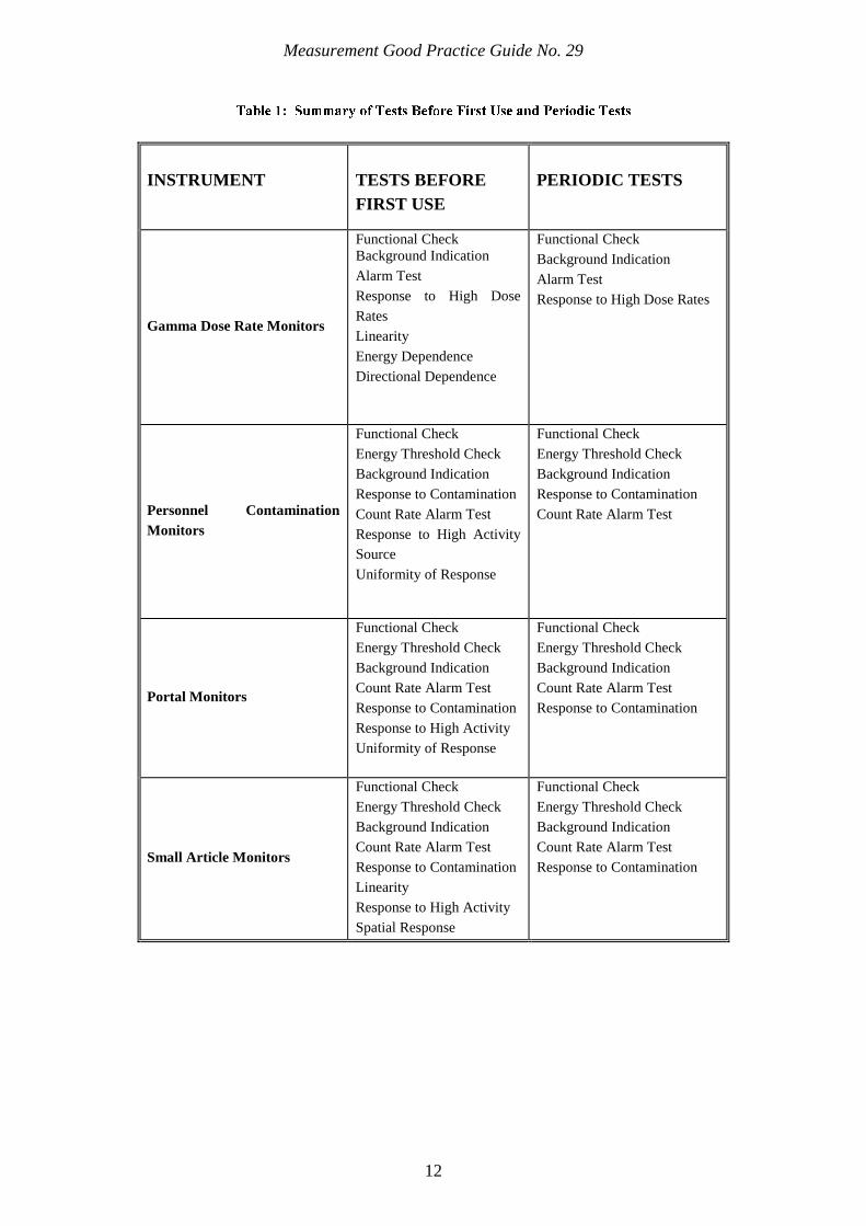
Table 1: Summary of Tests Before First Use and Periodic Tests ........................................... 12
Table 2: Tests Required for Gamma Dose Rate Monitors ...................................................... 18
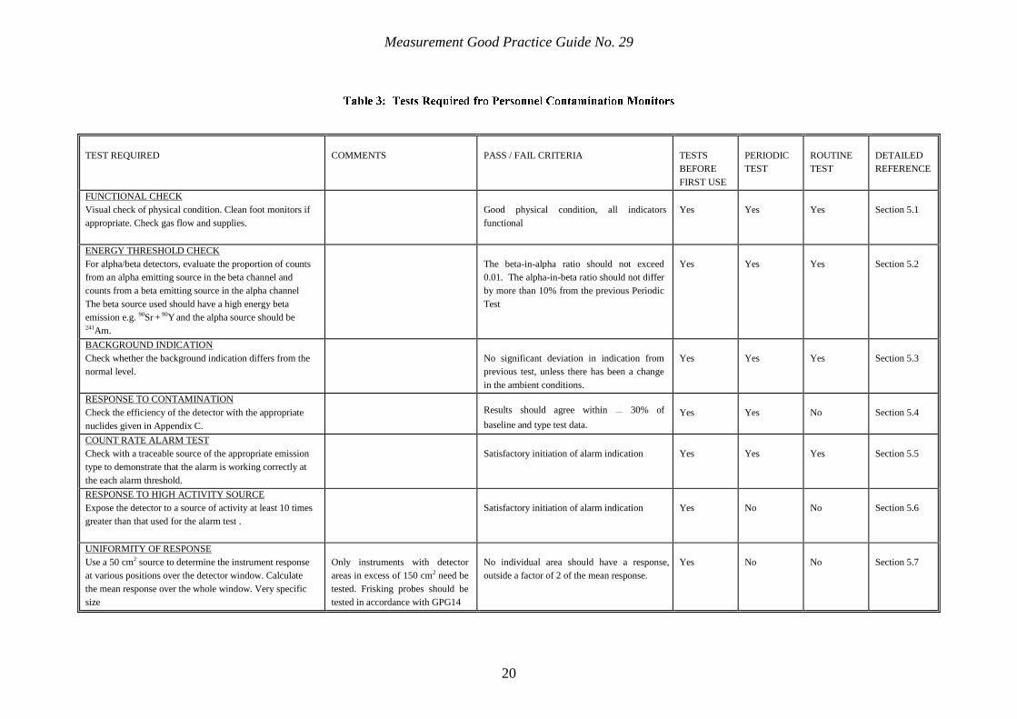
Table 3: Tests Required fro Personnel Contamination Monitors ........................................... 20
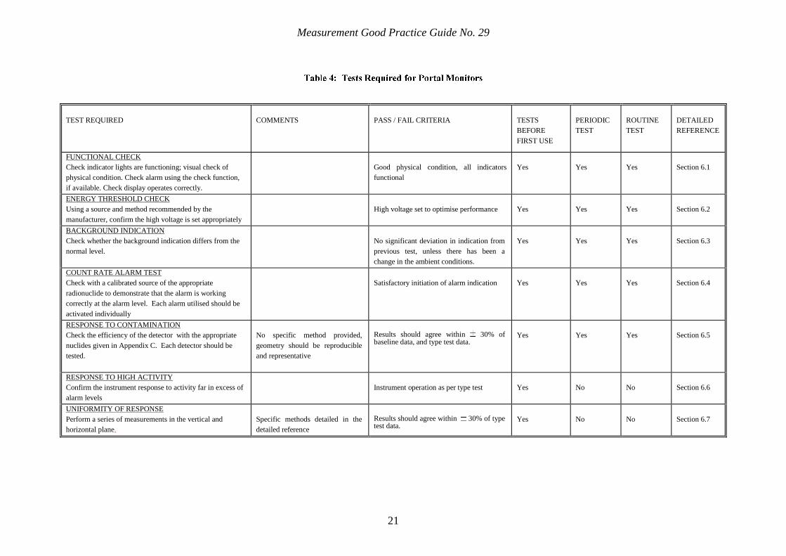
Table 4: Tests Required for Portal Monitors .......................................................................... 21
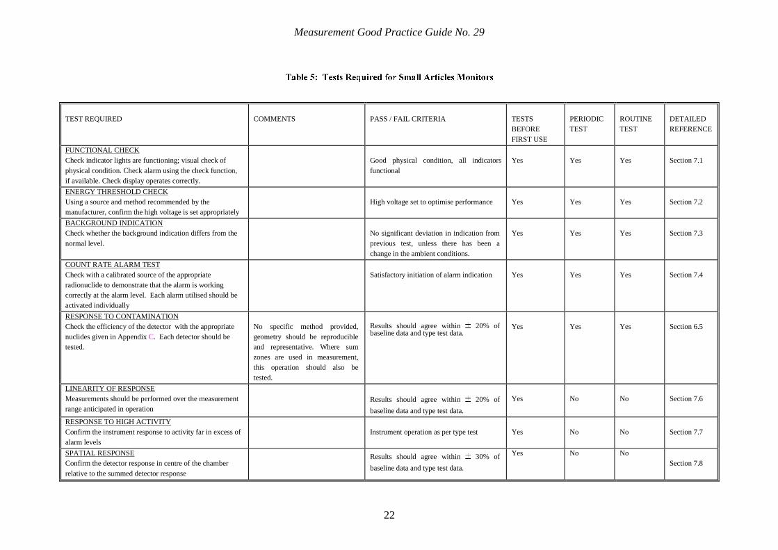
Table 5: Tests Required for Small Articles Monitors ............................................................. 22
Table 6: List of Suitable Check Radionuclides....................................................................... 65
ILLUSTRATIONS
Figure 1: Testing Regimes for Installed Instruments ................................................................ 7
Figure 2: Hand Contamination Monitor Calibration Source .................................................. 44
Figure 3: Frisking Contamination Monitor Calibration Jig .................................................... 45
Figure 4: Exit Contamination Monitor Calibration Jig (Ladder) ............................................ 46
Figure 5: Typical Steel Walled Energy Compensated GM Detector ...................................... 62
Figure 6: Pancake GM Detector ............................................................................................. 63

1
Introduction
IN THIS CHAPTER
11
Introduction

Measurement Good Practice Guide No. 29
2
The examination and testing of radiation protection instruments is a legal requirement
for those carrying out work with ionising radiations1, 2
. Sufficient equipment must be
available to comply with the regulations and the instruments must be examined, tested
and calibrated at appropriate intervals to ensure that they remain fit for use. Periodic
examination and testing of installed equipment would normally take place in the
workplace. This minimises risk of damage caused by removal, transport and re-
installation of equipment: it also permits testing of auxiliary indicators, such as remote
warning lights.
This Good Practice Guide provides recommended procedures for the general
examination, testing and calibration of installed radiation protection instruments. The
primary purpose of such equipment is protection of personnel and includes personnel
exit monitors and frisking equipment, portal monitors, Small Articles Monitors
(SAMS) and area gamma monitors. The scope of this document does not extend to
equipment used for the monitoring of airborne radioactive particulates, this guidance is
provided in GPG823, nor does it extend to installed environmental protection
instruments. Additionally, this document does not provide guidance associated with
the maintenance and examination of engineering controls. This guidance follows a
similar format to GPG144, which provides advice for portable radiation protection
instruments. Recommendations made in documents published by national and
international organisations, including the United Kingdom Accreditation Service
(UKAS), the International Organisation for Standardisation (ISO), the International
Electrotechnical Commission (IEC) and International Atomic Energy Agency (IAEA)5
have been consulted during the preparation of this Guide.
The objective of testing is to demonstrate that the instrument is suitable and fit for use.
The testing regimes contained herein have no legal standing and Employers may
implement their own schemes, provided they ensure compliance with the relevant
regulations.
The procedures detailed in this guidance provide the minimum level of testing that is
recommended for instruments used in normal operating conditions. There may be
special cases where testing requirements will go beyond these recommendations,
where instruments are used in conditions outside those envisaged in the standards
above. In such circumstances, the Employer may need to design appropriate test
procedures.
Due to the varied nature of the instruments covered in the Guide and their
applications, it is not always possible to specify complete calibration geometries and
suitable radionuclides. In these instances it is the responsibility of the Qualified
Person, in conjunction with the Radiation Protection Advisor, to define suitable test

Measurement Good Practice Guide No. 29
3
protocols to be employed for each instrument type to suit the application for which it
is used and the environment in which it operates.
A glossary of terms is contained in Section 11.
The types of instrument that are covered by this guidance are described in detail in
Section 3.
4
Testing Regime
IN THIS CHAPTER
22
Type Tests
Tests Before First Use
Periodic Tests
Routine Tests
Retest After Repair
Analysis of Test Results
Measurement Good Practice Guide No. 29
5
For the purposes of this guidance, a test is defined as a procedure to evaluate an
instrument‟s performance in order to establish its suitability, or its continued fitness,
for a particular type(s) of measurement in operational radiation protection. A test will
involve an element of calibration, which may be defined as the measurement of the
response of the instrument to known radiation fields. It is important to recognise that
the terms test and calibration are not synonymous: this is because a test will also
involve a degree of examination, which may include, for example, an inspection of
the mechanical and electrical state of the instrument.
Type Tests are laboratory tests that establish and confirm an instrument‟s
specification. The Type Tests are normally carried out by, or on behalf of, the
instrument manufacturer.
Manufacturer‟s Production Tests confirm a tolerance in production, confirming that
each instrument conforms to type and so meets specification. These tests may be
considered as factory acceptance tests (FAT) by an employer but they must be
undertaken by or under the direct supervision of a Qualified Person on behalf of the
Employer if they are intended to satisfy Test Before First Use requirements.
The tests required for compliance with current regulations are the Tests Before First
Use (TBFU) and Periodic Tests. The findings of these tests must be compared with
any previous test information and the appropriate Type Test to confirm that the
instrument is meeting its specification and is suitable for its intended use. TBFU and
Periodic Tests are carried out by, or on behalf of, the Employer. Table 1 lists
recommended TBFU and Periodic Tests.
Commissioning of an instrument may well include TBFU and/or establishing the
Baseline for subsequent Periodic Tests. Commissioning may also include the testing
of interfaces between instruments and their remote displays or safety or warning
devices.
Routine Tests and function checks are also recommended. A Routine Test includes
testing an instrument‟s response to traceable sources, e.g. alarm level testing. A
function check is a simple test carried out to ensure that the instrument appears to be
working correctly - it does not necessarily require the use of a radioactive source. For
gamma monitors it may include observation of response to any local radiation field
and/or any detector priming source. For contamination monitors a function check is
usually carried out together with routine maintenance such as detector cleaning,
checking foils, etc. Further details on recommended function checks can be found in
Sections 4 to 7.
Measurement Good Practice Guide No. 29
6
A Test after repair is required to ensure that instrument performance has been re-
established after repair. Depending on the nature of the repair, the scope of Test after
repair may be anything from function checks through to a new TBFU to provide a new
Periodic Test baseline.
All tests should be traceable and repeatable. A full record of test results, including
details of any significant adjustments made to the instrument, should be kept for a
minimum period of 2 years.
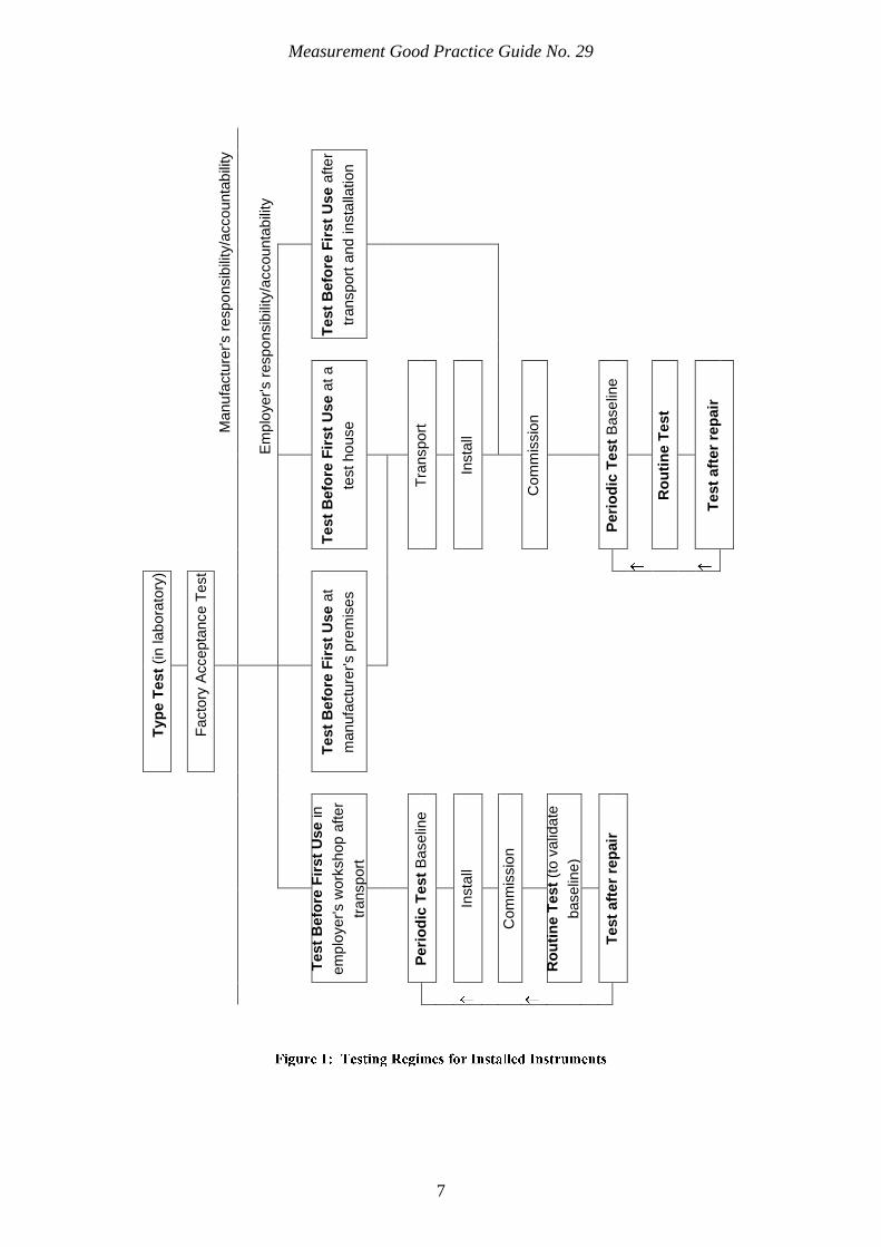
A summary of these tests and checks is shown in Figure 1 identifying the different
ways TBFU can be achieved in practice. The diagram is intended to show a variety of
possible routines but is not considered to be exhaustive.
Measurement Good Practice Guide No. 29
7
Manu
factu
rer's r
espo
nsib
ility
/accounta
bili
ty
Em
plo
yer's r
espo
nsib
ility
/accounta
bili
ty
Test
Befo
re F
irst
Use
afte
r
transport
and insta
llation
Test
Befo
re F
irst
Use
at a
test ho
use
Tra
nsport
Insta
ll
Com
mis
sio
n
Peri
od
ic T
est
Base
line
Ro
uti
ne T
est
Test
aft
er
rep
air
Typ
e T
est
(in lab
ora
tory
)
Facto
ry A
ccepta
nce T
est
Test
Befo
re F
irst
Use
at
manu
factu
rer's p
rem
ises
Test
Befo
re F
irst
Use
in
em
plo
yer's w
ork
shop a
fter
transport
Peri
od
ic T
est
Base
line
Insta
ll
Com
mis
sio
n
Ro
uti
ne T
est
(to v
alid
ate
baselin
e)
Test
aft
er
rep
air
Measurement Good Practice Guide No. 29
8
It is the responsibility of the Employer to ensure that an instrument is suitable for the
intended use before purchase. Decisions about instrument selection should be made
taking into account advice from an RPA, information from the manufacturer and other
authoritative data that might be available.
The body of information regarding the characteristics and expected performance of
instruments is called Type Test data and is usually based on recommendations from
international organisations such as IEC, ISO, etc. A number of IEC documents exist
which detail the tests that are appropriate for the Type Testing of particular types of
instrument. Typical documents for testing installed instrumentation are BS IEC
605326 for X- and gamma-ray dose rate monitors and BS EN 61098
7 for installed
contamination monitors and portal monitors. Although no standard fully addresses
contamination frisking monitors, parts of BS EN 603258, the standard for portable
contamination monitors, may also be applied to this type of equipment. Currently there
is no standard covering SAMs.
Type Tests are very comprehensive and may require specialised facilities: the tests
should be performed by someone with appropriate expertise and insight into the use of
instruments, in a laboratory with secondary standard or similar status, using
International Commission on Radiation Units and Measurements9 specified
measurement quantities, ISO876910
specified calibration sources and ISO403711
specified radiation beams.
For most new instruments, the manufacturers or suppliers provide Type Test data that
will enable the Employer to decide the necessary scope of TBFU. In the absence of
Type Test data, other sources of information, for example, published peer reviewed
evaluations, may be useful. When Type Test data are not available, or are insufficient
in the judgement of the QP and RPA, the Employer should perform their own Type
Test to establish their own baseline data at the TBFU stage.
Assuming that the instrument is delivered in good condition and set up according to its
specifications, the TBFU should demonstrate that the instrument conforms to type and
confirm its suitability for the intended use. The practicalities of TBFU are dependent
on whether an instrument is installed before or after TBFU. A gamma monitor, frisk
probe and ratemeter or a hand and foot monitor can be tested before installation but
this may be impractical for a large installed personnel exit monitor.
Measurement Good Practice Guide No. 29
9
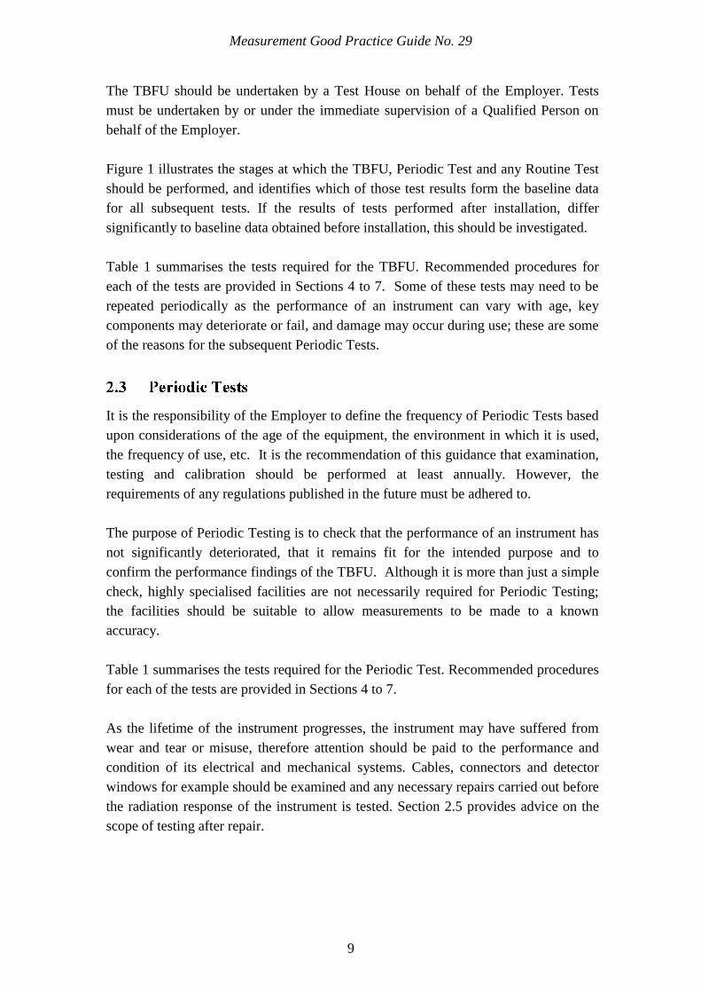
The TBFU should be undertaken by a Test House on behalf of the Employer. Tests
must be undertaken by or under the immediate supervision of a Qualified Person on
behalf of the Employer.
Figure 1 illustrates the stages at which the TBFU, Periodic Test and any Routine Test
should be performed, and identifies which of those test results form the baseline data
for all subsequent tests. If the results of tests performed after installation, differ
significantly to baseline data obtained before installation, this should be investigated.
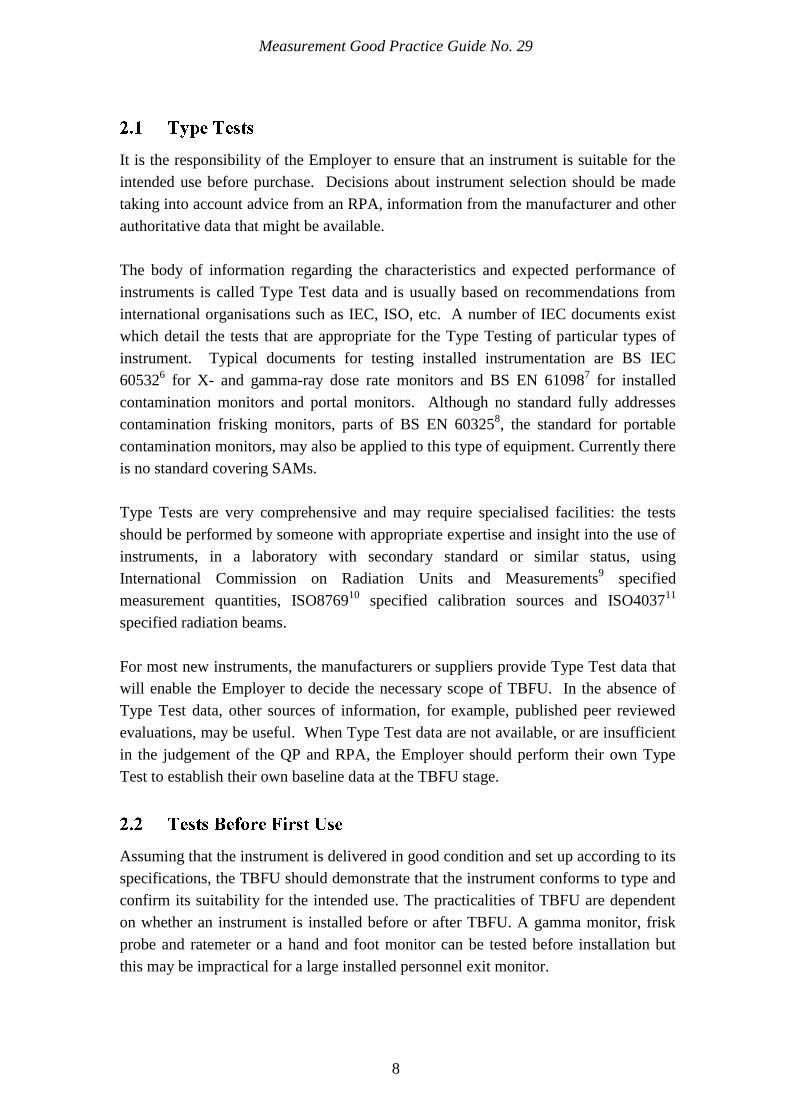
Table 1 summarises the tests required for the TBFU. Recommended procedures for
each of the tests are provided in Sections 4 to 7. Some of these tests may need to be
repeated periodically as the performance of an instrument can vary with age, key
components may deteriorate or fail, and damage may occur during use; these are some
of the reasons for the subsequent Periodic Tests.
It is the responsibility of the Employer to define the frequency of Periodic Tests based
upon considerations of the age of the equipment, the environment in which it is used,
the frequency of use, etc. It is the recommendation of this guidance that examination,
testing and calibration should be performed at least annually. However, the
requirements of any regulations published in the future must be adhered to.
The purpose of Periodic Testing is to check that the performance of an instrument has
not significantly deteriorated, that it remains fit for the intended purpose and to
confirm the performance findings of the TBFU. Although it is more than just a simple
check, highly specialised facilities are not necessarily required for Periodic Testing;
the facilities should be suitable to allow measurements to be made to a known
accuracy.
Table 1 summarises the tests required for the Periodic Test. Recommended procedures
for each of the tests are provided in Sections 4 to 7.
As the lifetime of the instrument progresses, the instrument may have suffered from
wear and tear or misuse, therefore attention should be paid to the performance and
condition of its electrical and mechanical systems. Cables, connectors and detector
windows for example should be examined and any necessary repairs carried out before
the radiation response of the instrument is tested. Section 2.5 provides advice on the
scope of testing after repair.
Measurement Good Practice Guide No. 29
10
The critical role that many installed monitors play in maintaining safe working
conditions is such that a subset of the Periodic Tests should be conducted on a more
frequent basis e.g. weekly or monthly depending on the instrument type and use.
Table 1 indicates which tests should be included in Routine Tests for each instrument
type.
The Employer should be satisfied, on the basis of a risk assessment, that the frequency
of Routine Tests and the recommended subset of tests are sufficient for his own work
situation. Typical criteria to consider in the risk assessment would include the time
between breakdowns, the probability and consequences of a failure, and the occupancy
of the area which the monitor serves.
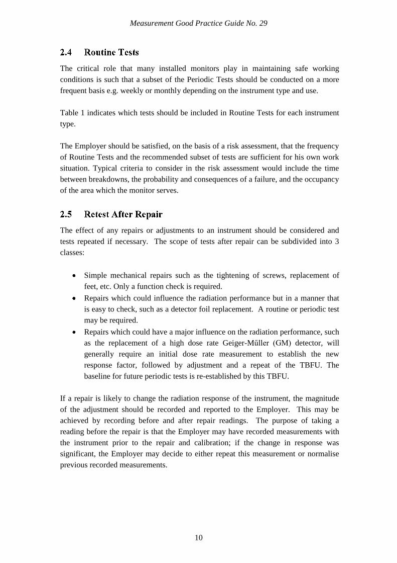
The effect of any repairs or adjustments to an instrument should be considered and
tests repeated if necessary. The scope of tests after repair can be subdivided into 3
classes:
Simple mechanical repairs such as the tightening of screws, replacement of
feet, etc. Only a function check is required.
Repairs which could influence the radiation performance but in a manner that
is easy to check, such as a detector foil replacement. A routine or periodic test
may be required.
Repairs which could have a major influence on the radiation performance, such
as the replacement of a high dose rate Geiger-Műller (GM) detector, will
generally require an initial dose rate measurement to establish the new
response factor, followed by adjustment and a repeat of the TBFU. The
baseline for future periodic tests is re-established by this TBFU.
If a repair is likely to change the radiation response of the instrument, the magnitude
of the adjustment should be recorded and reported to the Employer. This may be
achieved by recording before and after repair readings. The purpose of taking a
reading before the repair is that the Employer may have recorded measurements with
the instrument prior to the repair and calibration; if the change in response was
significant, the Employer may decide to either repeat this measurement or normalise
previous recorded measurements.
Measurement Good Practice Guide No. 29
11
In order to confirm that the instrument still conforms to type and remains fit for
purpose, the results of the TBFU should be compared with the Type Test data; these
TBFU results then form the baseline for all subsequent tests.
A full record of test results must be kept in accordance with the regulations. It is good
practice to maintain details of any adjustments made to the instrument. Current test
results should be compared with previous results and any significant changes noted
and investigated, even if all the results fall within specification. For example, the
performance of an instrument should be regarded as suspicious if a previously
consistent response is now significantly different, even if it is still within acceptable
limits.
Whenever an instrument is adjusted during the course of testing, a statement indicating
the nature and magnitude of the adjustment should be made on the test report.
An instrument may fail the TBFU or Periodic Tests if the results of any component of
the appropriate tests are not within the acceptable limits defined in Tables 2 to 5, or if
the instrument‟s performance is deemed unsatisfactory by the QP. In this way the
TBFU record is maintained as the baseline for subsequent tests.
Measurement Good Practice Guide No. 29
12
INSTRUMENT
TESTS BEFORE
FIRST USE
PERIODIC TESTS
Gamma Dose Rate Monitors
Functional Check
Background Indication
Alarm Test
Response to High Dose
Rates
Linearity
Energy Dependence
Directional Dependence
Functional Check
Background Indication
Alarm Test
Response to High Dose Rates
Personnel Contamination
Monitors
Functional Check
Energy Threshold Check
Background Indication
Response to Contamination
Count Rate Alarm Test
Response to High Activity
Source
Uniformity of Response
Functional Check
Energy Threshold Check
Background Indication
Response to Contamination
Count Rate Alarm Test
Portal Monitors
Functional Check
Energy Threshold Check
Background Indication
Count Rate Alarm Test
Response to Contamination
Response to High Activity
Uniformity of Response
Functional Check
Energy Threshold Check
Background Indication
Count Rate Alarm Test
Response to Contamination
Small Article Monitors
Functional Check
Energy Threshold Check
Background Indication
Count Rate Alarm Test
Response to Contamination
Linearity
Response to High Activity
Spatial Response
Functional Check
Energy Threshold Check
Background Indication
Count Rate Alarm Test
Response to Contamination

13
Instruments
IN THIS CHAPTER
33
Gamma Dose Rate Monitors
Personnel Contamination Monitors
Portal Monitors
Small Article Monitors
Measurement Good Practice Guide No. 29
14
Installed radiation protection instruments will normally include an audible and/or
visual alarm indication as a minimum. Some instruments may also have a readout
meter in the form of an analogue and/or digital reading. Instruments without alarm
functions, referred to as meters, are included within the following descriptions.
A gamma dose rate monitor is designed to display an audible or visual alarm (or both)
when the local dose rate exceeds the preset alarm threshold on the instrument. It may
also display the local dose rate on a meter. Most modern gamma monitors have a
detector fail alarm facility which is often held off with a radioactive priming source.
This facility allows the instrument to perform self-checks continuously: the instrument
electronics will inform the user if there is a detector fault such that the expected pulse
rate from the detector is not received by the associated electronics. Instruments
without either a priming source or detector fail alarm will have no built in detector
checks.
For the tests defined in this guidance, installed gamma dose rate monitors may be
divided into three classes:
Class A Monitors with a priming source and with a detector fail alarm.
Class A gamma monitors have a priming source fitted to the detector to produce a
definite count rate or current at background levels. These are generally instruments
with low sensitivities where the natural background count rate is too low to be able to
give confidence that the detector is functioning.
Class B Monitors with a detector fail alarm only.
Class B gamma monitors are similar to Class A monitors, but are generally more
sensitive and do not require a priming source to trigger detector fail alarm.
Class C Monitors with no priming source and with no detector fail alarm.
Class C gamma monitors do not have detector fail alarm functionality. Installation of
these instruments for radiation protection purposes is not generally recommended,
however, they may continue to serve a useful function in low risk situations.
These classes are relevant to the background indication and influence the frequency of
the alarm test and functional check.
The tests required to establish the linearity, energy dependence, directional
dependence and other relevant characteristics of installed gamma dose rate monitors
Measurement Good Practice Guide No. 29
15
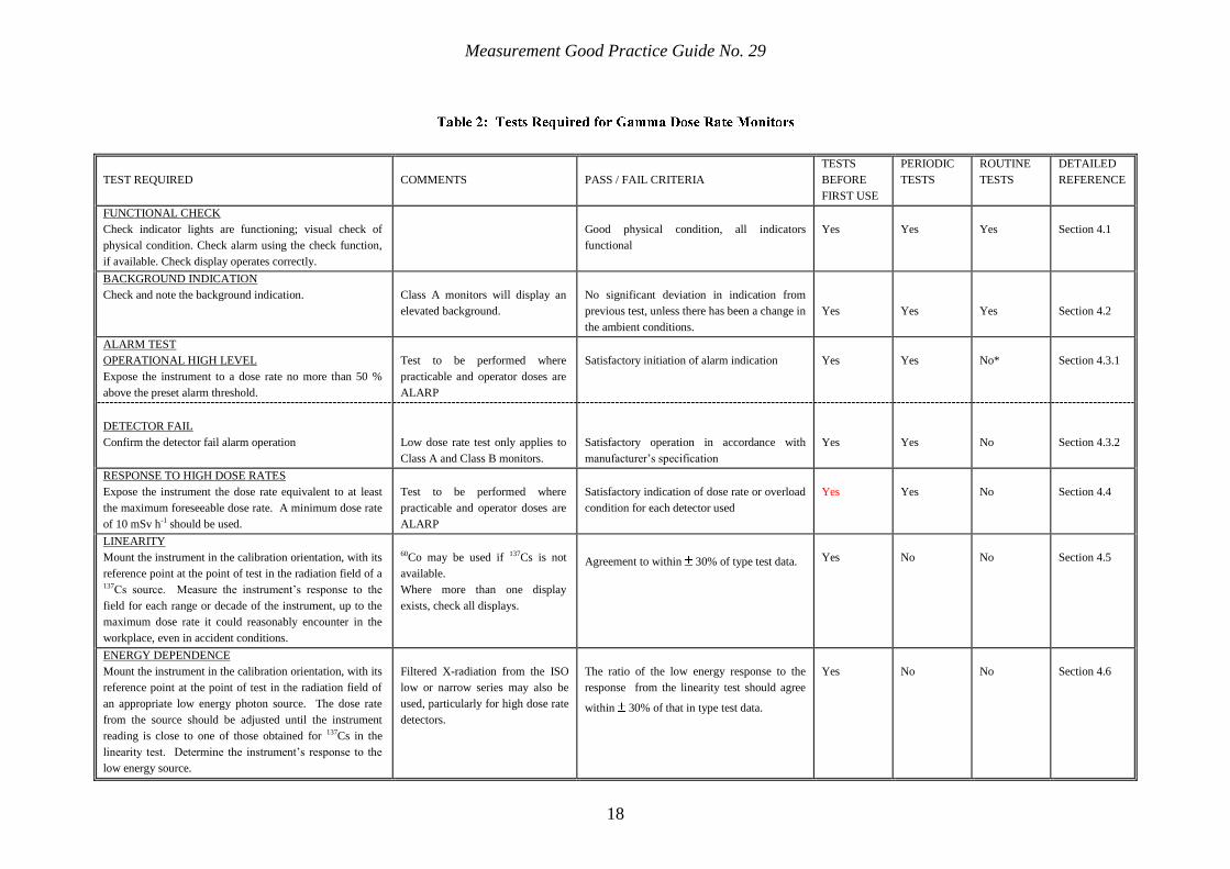
are detailed in Section 4. Table 2 is a quick reference guide for these monitors and
provides a brief description of each of the tests.
The three types of personnel contamination monitor are described below. Modern
installed contamination instruments monitor the background count rate while they are
not monitoring personnel. The monitor therefore compensates for any changes in
background. Tests are required to ensure that the alarm threshold will operate at an
appropriate contamination level.
It is important that the alarm threshold on these instruments is set to activate at the
appropriate surface contamination level. Reference should be made to „The Selection
of Alarm Levels for Personnel Exit Monitors‟ published by Industry Radiological
Protection Co-ordination Group12
.
Typically these instruments are supplied to monitor hands only, feet only or both
simultaneously. The detectors are static and the hands and/or feet are monitored when
in contact with the detector. The monitoring time is depending on how the instrument
has been set up. An outline of the tests required for hand and foot monitors is given in
Table 3 and more information is provided in Section 5. For those monitors fitted with
frisking probes, the probes should be tested as Section 3.2.2 below.
These instruments consist of a probe connected to a monitoring assembly. The users
monitor themselves by moving the probe slowly over their body. Other types of
contamination monitor may have position sensors, e.g. for hands, feet, closeness of the
body to arrays of detectors, but frisking monitors rely entirely on the self-monitoring
method adopted by the user. An outline of the tests required for frisking monitors is
given in Table 3 and more information is provided in Section 5.
In some situations a portable contamination monitor may be fixed to a location and
used as a frisking monitor. In this situation, the monitor should be tested in
accordance with the recommendations of GPG144.
These instruments typically consist of an array of detectors to monitor for
contamination on the body, hands and feet. The user is normally required to position
themselves against this array for a short, period of time.
Measurement Good Practice Guide No. 29
16
A brief description of the tests required for exit monitors is provided in Table 3 while
detailed information can be found in Section 5. Note that some detector housings may
contain multiple separate detectors each with more than one channel; each channel
should be tested.
3.2.3.1
These instruments are designed to monitor alpha and/or beta emitting contamination
on the body. Typically this is achieved by an array of detectors mounted close
together. These also incorporate the hand and foot detectors as described in Section
3.2.1.
3.2.3.2
Alpha and/or beta contamination monitoring instruments may be supplemented with
additional gamma scintillation detectors. These detectors are designed to be sensitive
to higher energy gamma emissions, typically of energy in excess of 60 keV. They are
designed to monitor contamination where alpha and beta emissions may be shielded
by clothing or the user‟s body, or where only photons are emitted. Each detector may
be configured with an alarm. An outline of the tests required for these monitors is
provided in Section 6.
These instruments are used to monitor personnel for beta and/or gamma emitting
contamination. They are designed for both „walkthrough‟ mode and well as „standing
stationary‟ mode. The guidance provided in this document is intended to satisfy the
IRRs. However, similar systems may be employed for other purposes and the
principles of this guidance may be extended to cover these applications.
An outline of the tests required for Personnel Portal Monitors is given in Table 4 and
more information is provided in Section 6. Each detector should be tested.
Small Articles Monitors (SAMs) are designed to monitor photon emitting
contamination on, or in, articles such as tools, hand held instruments and personal
artefacts. Typically they have 2, 4 or 6 gamma scintillation detectors which are
mounted around a cuboid chamber. Alarms are normally set based upon the summed
response of the detectors. Doors are often employed to control the release of the
articles from the controlled area.
SAMs may also be incorporated within an exit monitor and may utilise alpha and/or
beta detectors as well as gamma detectors.

Measurement Good Practice Guide No. 29
17
SAMs may be designed with an internal or external weighscale, for the purpose of
measuring the specific activity of an article. The specific activity mode of operation is
outside the scope of this guidance document, however, it may be convenient to test the
functionality of the weighscale at the same time as the radiation testing.
An outline of the tests required for SAMs is given in Table 5 and more information is
provided in Section 7.
Measurement Good Practice Guide No. 29
18
TEST REQUIRED
COMMENTS
PASS / FAIL CRITERIA
TESTS
BEFORE
FIRST USE
PERIODIC
TESTS
ROUTINE
TESTS
DETAILED
REFERENCE
FUNCTIONAL CHECK
Check indicator lights are functioning; visual check of
physical condition. Check alarm using the check function,
if available. Check display operates correctly.
Good physical condition, all indicators
functional
Yes
Yes
Yes
Section 4.1
BACKGROUND INDICATION
Check and note the background indication.
Class A monitors will display an
elevated background.
No significant deviation in indication from
previous test, unless there has been a change in
the ambient conditions.
Yes
Yes
Yes
Section 4.2
ALARM TEST
OPERATIONAL HIGH LEVEL
Expose the instrument to a dose rate no more than 50 %
above the preset alarm threshold.
Test to be performed where
practicable and operator doses are
ALARP
Satisfactory initiation of alarm indication
Yes
Yes
No*
Section 4.3.1
DETECTOR FAIL
Confirm the detector fail alarm operation
Low dose rate test only applies to
Class A and Class B monitors.
Satisfactory operation in accordance with
manufacturer‟s specification
Yes
Yes
No
Section 4.3.2
RESPONSE TO HIGH DOSE RATES
Expose the instrument the dose rate equivalent to at least
the maximum foreseeable dose rate. A minimum dose rate
of 10 mSv h-1 should be used.
Test to be performed where
practicable and operator doses are
ALARP
Satisfactory indication of dose rate or overload
condition for each detector used
Yes
Yes
No
Section 4.4
LINEARITY
Mount the instrument in the calibration orientation, with its
reference point at the point of test in the radiation field of a 137Cs source. Measure the instrument‟s response to the
field for each range or decade of the instrument, up to the
maximum dose rate it could reasonably encounter in the
workplace, even in accident conditions.
60Co may be used if 137Cs is not
available.
Where more than one display
exists, check all displays.
Agreement to within 30% of type test data.
Yes
No
No
Section 4.5
ENERGY DEPENDENCE
Mount the instrument in the calibration orientation, with its
reference point at the point of test in the radiation field of
an appropriate low energy photon source. The dose rate
from the source should be adjusted until the instrument
reading is close to one of those obtained for 137Cs in the
linearity test. Determine the instrument‟s response to the
low energy source.
Filtered X-radiation from the ISO
low or narrow series may also be
used, particularly for high dose rate
detectors.
The ratio of the low energy response to the
response from the linearity test should agree
within 30% of that in type test data.
Yes
No
No
Section 4.6
Measurement Good Practice Guide No. 29
19
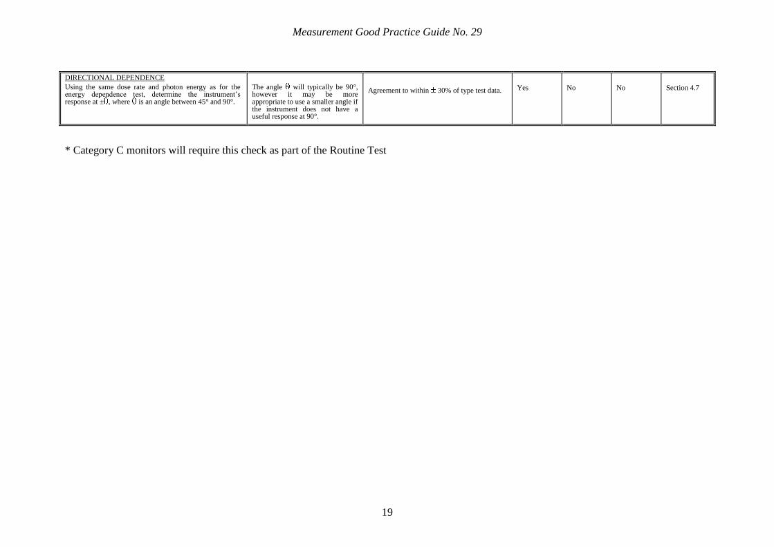
DIRECTIONAL DEPENDENCE
Using the same dose rate and photon energy as for the energy dependence test, determine the instrument‟s response at ± , where is an angle between 45° and 90°.
The angle will typically be 90°, however it may be more appropriate to use a smaller angle if the instrument does not have a useful response at 90°.
Agreement to within 30% of type test data.
Yes
No
No
Section 4.7
* Category C monitors will require this check as part of the Routine Test
Measurement Good Practice Guide No. 29
20
TEST REQUIRED
COMMENTS
PASS / FAIL CRITERIA
TESTS
BEFORE
FIRST USE
PERIODIC
TEST
ROUTINE
TEST
DETAILED
REFERENCE
FUNCTIONAL CHECK
Visual check of physical condition. Clean foot monitors if
appropriate. Check gas flow and supplies.
Good physical condition, all indicators
functional
Yes
Yes
Yes
Section 5.1
ENERGY THRESHOLD CHECK
For alpha/beta detectors, evaluate the proportion of counts
from an alpha emitting source in the beta channel and
counts from a beta emitting source in the alpha channel The beta source used should have a high energy beta
emission e.g. 90Sr + 90Y and the alpha source should be 241Am.
The beta-in-alpha ratio should not exceed
0.01. The alpha-in-beta ratio should not differ
by more than 10% from the previous Periodic
Test
Yes
Yes
Yes
Section 5.2
BACKGROUND INDICATION
Check whether the background indication differs from the
normal level.
No significant deviation in indication from
previous test, unless there has been a change
in the ambient conditions.
Yes
Yes
Yes
Section 5.3
RESPONSE TO CONTAMINATION
Check the efficiency of the detector with the appropriate
nuclides given in Appendix C.
Results should agree within 30% of
baseline and type test data.
Yes
Yes
No
Section 5.4
COUNT RATE ALARM TEST
Check with a traceable source of the appropriate emission
type to demonstrate that the alarm is working correctly at
the each alarm threshold.
Satisfactory initiation of alarm indication
Yes
Yes
Yes
Section 5.5
RESPONSE TO HIGH ACTIVITY SOURCE
Expose the detector to a source of activity at least 10 times
greater than that used for the alarm test .
Satisfactory initiation of alarm indication
Yes
No
No
Section 5.6
UNIFORMITY OF RESPONSE
Use a 50 cm2 source to determine the instrument response
at various positions over the detector window. Calculate
the mean response over the whole window. Very specific
size
Only instruments with detector
areas in excess of 150 cm2 need be
tested. Frisking probes should be
tested in accordance with GPG14
No individual area should have a response,
outside a factor of 2 of the mean response.
Yes
No
No
Section 5.7
Measurement Good Practice Guide No. 29
21
TEST REQUIRED
COMMENTS
PASS / FAIL CRITERIA
TESTS
BEFORE
FIRST USE
PERIODIC
TEST
ROUTINE
TEST
DETAILED
REFERENCE
FUNCTIONAL CHECK
Check indicator lights are functioning; visual check of
physical condition. Check alarm using the check function,
if available. Check display operates correctly.
Good physical condition, all indicators
functional
Yes
Yes
Yes
Section 6.1
ENERGY THRESHOLD CHECK
Using a source and method recommended by the
manufacturer, confirm the high voltage is set appropriately
High voltage set to optimise performance
Yes
Yes
Yes
Section 6.2
BACKGROUND INDICATION
Check whether the background indication differs from the
normal level.
No significant deviation in indication from
previous test, unless there has been a
change in the ambient conditions.
Yes
Yes
Yes
Section 6.3
COUNT RATE ALARM TEST
Check with a calibrated source of the appropriate
radionuclide to demonstrate that the alarm is working
correctly at the alarm level. Each alarm utilised should be
activated individually
Satisfactory initiation of alarm indication
Yes
Yes
Yes
Section 6.4
RESPONSE TO CONTAMINATION
Check the efficiency of the detector with the appropriate
nuclides given in Appendix C. Each detector should be
tested.
No specific method provided,
geometry should be reproducible
and representative
Results should agree within 30% of baseline data, and type test data.
Yes
Yes
Yes
Section 6.5
RESPONSE TO HIGH ACTIVITY
Confirm the instrument response to activity far in excess of
alarm levels
Instrument operation as per type test
Yes
No
No
Section 6.6
UNIFORMITY OF RESPONSE
Perform a series of measurements in the vertical and
horizontal plane.
Specific methods detailed in the
detailed reference
Results should agree within 30% of type test data.
Yes
No
No
Section 6.7
Measurement Good Practice Guide No. 29
22
TEST REQUIRED
COMMENTS
PASS / FAIL CRITERIA
TESTS
BEFORE
FIRST USE
PERIODIC
TEST
ROUTINE
TEST
DETAILED
REFERENCE
FUNCTIONAL CHECK
Check indicator lights are functioning; visual check of
physical condition. Check alarm using the check function,
if available. Check display operates correctly.
Good physical condition, all indicators
functional
Yes
Yes
Yes
Section 7.1
ENERGY THRESHOLD CHECK
Using a source and method recommended by the
manufacturer, confirm the high voltage is set appropriately
High voltage set to optimise performance
Yes
Yes
Yes
Section 7.2
BACKGROUND INDICATION
Check whether the background indication differs from the
normal level.
No significant deviation in indication from
previous test, unless there has been a
change in the ambient conditions.
Yes
Yes
Yes
Section 7.3
COUNT RATE ALARM TEST
Check with a calibrated source of the appropriate
radionuclide to demonstrate that the alarm is working
correctly at the alarm level. Each alarm utilised should be
activated individually
Satisfactory initiation of alarm indication
Yes
Yes
Yes
Section 7.4
RESPONSE TO CONTAMINATION
Check the efficiency of the detector with the appropriate
nuclides given in Appendix C. Each detector should be
tested.
No specific method provided,
geometry should be reproducible
and representative. Where sum
zones are used in measurement,
this operation should also be
tested.
Results should agree within 20% of baseline data and type test data.
Yes
Yes
Yes
Section 6.5
LINEARITY OF RESPONSE
Measurements should be performed over the measurement
range anticipated in operation
Results should agree within 20% of
baseline data and type test data.
Yes
No
No
Section 7.6
RESPONSE TO HIGH ACTIVITY
Confirm the instrument response to activity far in excess of
alarm levels
Instrument operation as per type test
Yes
No
No
Section 7.7
SPATIAL RESPONSE
Confirm the detector response in centre of the chamber
relative to the summed detector response
Results should agree within 30% of
baseline data and type test data.
Yes No No
Section 7.8
Measurement Good Practice Guide No. 29
23

Measurement Good Practice Guide No. 29
24
Specific Tests for
Gamma Dose
Rate Monitors
IN THIS CHAPTER
44
Functional Check
Background Indication
Alarm Test
Response to High Dose Rates
Linearity of Response
Energy Dependence of Gamma Monitors
Directional Dependence
Measurement Good Practice Guide No. 29
25
Table 1 lists the tests, which are applicable to the TBFU and Periodic Tests for gamma
monitors. Table 2 provides a brief summary of the tests for gamma monitors and
analysis of test results: the tables are not comprehensive and should not be used
without reference to the detailed information in the sections of text. The tests may be
performed in an order that is convenient to the Test House. If the response to high
dose rates is not tested first, it is important to check that this test, when conducted
subsequently, has not adversely affected other aspects of the instrument performance.
Full procedures for the performance of all of the tests are provided in the remainder of
this Section.
Perform a visual check of the physical condition of the instrument. Check that
indicator lights are functioning. Note the threshold at which the alarm is activated.
Check the alarm using any check function available; this should ensure that both
audible and visual indicators work correctly.
If the instrument has a digital display and has a display check function, check that all
segments of the display work correctly.
If Class C instruments are in service, due to the absence of low level alarm, functional
checks should be performed with increased frequency (e.g. daily) to maintain
confidence that they still provide the required level of protection.
Obtain a background measurement and compare with baseline data; any significant
deviation in indication should be investigated unless there has been a change in
ambient conditions.
Where the function exists, expose the instrument to a dose rate no more than 50%
above the defined alarm threshold and confirm that the alarm is activated.
Some instruments use two detectors, one of which is relatively sensitive and operates
at low dose rates and a much less sensitive one which takes over automatically and
provides the indication at higher dose rates. Normally, the operational alarm will be
triggered by the sensitive detector and a simple alarm function test will often not check
the high dose rate detector. It is important to confirm that the alarm operates correctly
up to the maximum radiation level that could be encountered.
Measurement Good Practice Guide No. 29
26
If the monitor is routinely exposed to a reproducible radiation field e.g. radiation cell
interlock monitor, proof that the monitor responds in an expected manner may satisfy
this check.
Many instrument designs are equipped with an alarm latch, which holds the alarm on,
even if the dose rate has dropped below the alarm level. Where the function exists, the
operation of the alarm latch should be confirmed.
The response time for the alarm to be initiated should be recorded and be within the
response time specified by the RPA.
Class C monitors must undergo an alarm test on a routine basis. Where the instrument
is operating in an area with an enhanced background dose rate, such that instrument
reading is always within the first decade of the measurement, the Employer may
justify the relaxation of the routine alarm test. However the Employer should note, on
a routine basis, that the monitor continues to detect the enhanced background dose
rate.
Where practicable, activate the Detector Fail Alarm to ensure it operates in accordance
with manufacture‟s specifications. Where the Detector Fail Alarm does not operate as
anticipated this should be investigated. The instrument manufacturer should be
consulted as to an appropriate method to conduct this test.
Failure of equipment or operational procedure could lead to dose rates far beyond
those routinely encountered. This possibility should have been recognised in a risk
assessment and a suitable instrument selected that has been type tested up to a
sufficiently high dose rate. Where practicable, the instrument should be tested to at
least the maximum dose rate it could encounter. Where this is not practicable, the
instrument should be tested to as high a dose rate as practicable and then an analysis
made of the instrument function to confirm that there is no reasonable possibility of its
failure to danger at dose rates above those tested. This requires a detailed
understanding of how the instrument operates; in particular the detector, polarising
supply, input amplifier and subsequent electronics.
It is important to ensure that the high dose rate test has not damaged the instrument,
for example, leading to a high background count rate after the test. The test should
therefore take place early in the testing routine, before the alarm test. It is also good
practice to check the instrument indication at an elevated dose rate level before and
Measurement Good Practice Guide No. 29
27
after the high dose rate test. Any significant change should cast doubt on the
appropriateness of the instrument for that application. It should be noted that Geiger
Muller detectors have a life of only about 1011
counts, so high dose rate exposure test
times should be kept short. This does not mean that such instruments are unsuitable for
potential very high dose rates, provided such levels are infrequent and of short
duration.
Where more than one detector is used to provide operation over an extended dose rate
range, the performance of the low dose rate detector should be confirmed during the
high dose rate test. Typically this is displayed as OFLOW or ------. It is not unknown
for the low dose rate detector to fail at high dose rates therefore impacting upon
operation of the instrument as a whole.
The instrument should be tested with the alarm latch off, to ensure that the alarm does
not stop at very high dose rates. It should then be turned on and checked by exceeding
the alarm level, observing a correct response, then reducing the dose rate below the
alarm level and confirming that the alarm indications continue.
Where in-situ periodic testing is chosen, instruments should normally be tested up to at
least 10 mSv h-1
. This can be achieved safely in the workplace using a collimated
source mounted close to the detector using a jig, which provides reproducible
geometry.
Where there is a possibility of dose rates much greater than 10 mSv h-1
then, where
practicable, the instrument should be exposed during the periodic test to a dose rate
which will confirm that the instrument functions correctly at these dose rates.
Additional guidance for deriving reference dose rates and performing tests is provided
in Appendix A.
The instrument under test should be mounted in the calibration orientation, with its
reference point (marked calibration point on the detector or detector housing), or in
the absence of a marked calibration point, the geometric centre of the detector, at the
point of test in the radiation field from 137
Cs gamma radiation; 60
Co may be used as an
alternative source. A combination of both gamma radiations may be used, where the
appropriate range of dose rates from 137
Cs is not available. The instrument‟s response
to the field should be measured for at least one dose rate in each range or decade of
the instrument, up to the maximum dose rate which it could reasonably encounter in
the workplace, even under accident conditions. If the response of an instrument is
Measurement Good Practice Guide No. 29
28
found to be unsatisfactory, it may be possible in some cases for the instrument to be
adjusted to give an acceptable response over its range of use. Any adjustment made
should be reported on the test report by displaying a before and after adjustment
reading (or response).
Where appropriate, the test report should give the instrument response or
calibration/multiplication factors which enable the user to convert the instrument
indication to dose rate, or quote that the instrument‟s response is acceptable within a
specified range of dose rates, or that it has been adjusted to be acceptable within the
range. The instrument responses in the known calibration fields should be within
±30% of the baseline data and ideally within ±30% of the true dose rate. Any untested
ranges or decades should be clearly indicated on the test report.
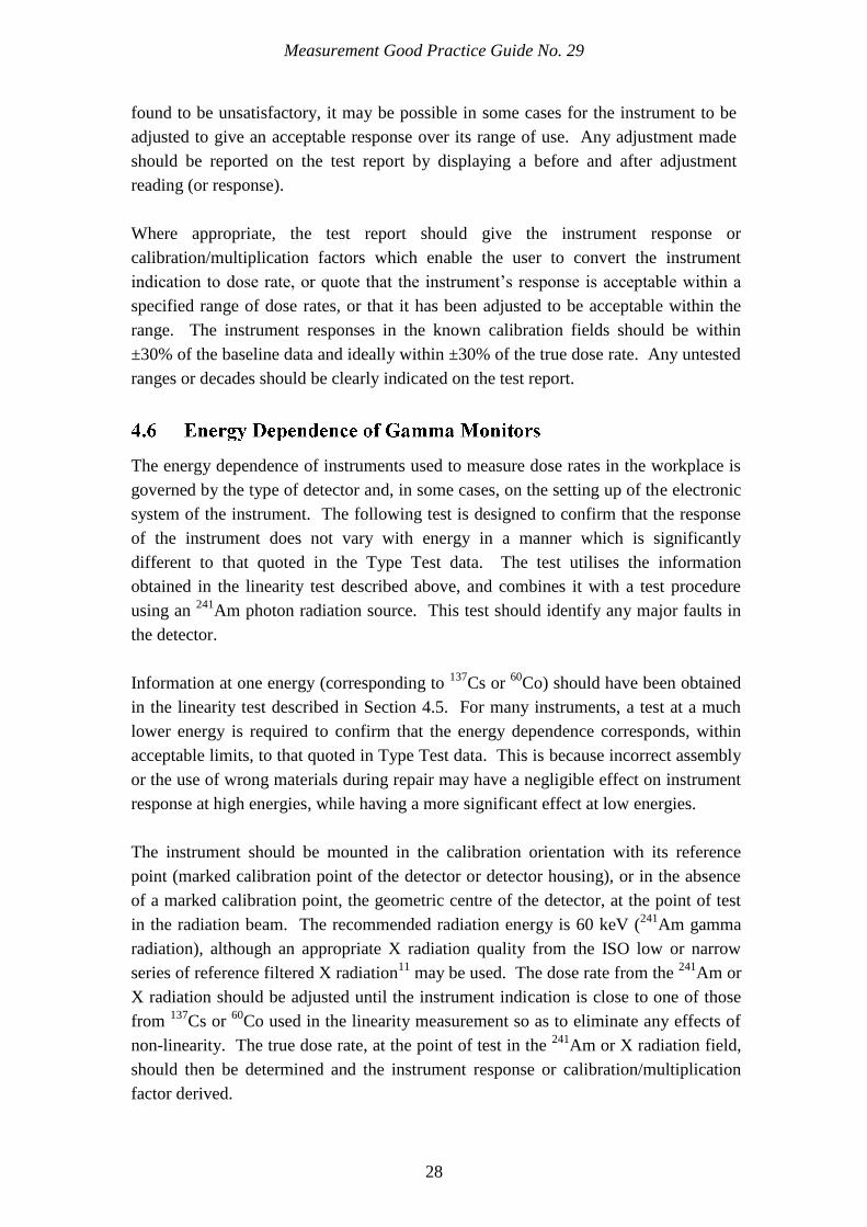
The energy dependence of instruments used to measure dose rates in the workplace is
governed by the type of detector and, in some cases, on the setting up of the electronic
system of the instrument. The following test is designed to confirm that the response
of the instrument does not vary with energy in a manner which is significantly
different to that quoted in the Type Test data. The test utilises the information
obtained in the linearity test described above, and combines it with a test procedure
using an 241
Am photon radiation source. This test should identify any major faults in
the detector.
Information at one energy (corresponding to 137
Cs or 60
Co) should have been obtained
in the linearity test described in Section 4.5. For many instruments, a test at a much
lower energy is required to confirm that the energy dependence corresponds, within
acceptable limits, to that quoted in Type Test data. This is because incorrect assembly
or the use of wrong materials during repair may have a negligible effect on instrument
response at high energies, while having a more significant effect at low energies.
The instrument should be mounted in the calibration orientation with its reference
point (marked calibration point of the detector or detector housing), or in the absence
of a marked calibration point, the geometric centre of the detector, at the point of test
in the radiation beam. The recommended radiation energy is 60 keV (241
Am gamma
radiation), although an appropriate X radiation quality from the ISO low or narrow
series of reference filtered X radiation11
may be used. The dose rate from the 241
Am or
X radiation should be adjusted until the instrument indication is close to one of those
from 137
Cs or 60
Co used in the linearity measurement so as to eliminate any effects of
non-linearity. The true dose rate, at the point of test in the 241
Am or X radiation field,
should then be determined and the instrument response or calibration/multiplication
factor derived.
Measurement Good Practice Guide No. 29
29
The ratio of the low energy response to that for 137
Cs or 60
Co gamma radiation should
be calculated and compared with the same ratio derived as the type test data. The ratios
should agree to within 30%. Caution should be exercised when comparing 241
Am to 137
Cs response ratio with a 60 keV X radiation to 137
Cs response ratio due to the fact
that the X-radiation is emitted with a range of energies while the emission from 241
Am
is effectively mono-energetic; as a consequence the instrument‟s response is unlikely
to be identical to the two radiations.
Where an instrument uses more than one detector, this test should be performed on
each detector.
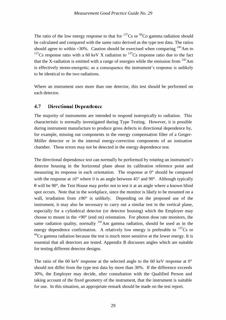
The majority of instruments are intended to respond isotropically to radiation. This
characteristic is normally investigated during Type Testing. However, it is possible
during instrument manufacture to produce gross defects in directional dependence by,
for example, missing out components in the energy compensation filter of a Geiger-
Müller detector or in the internal energy-correction components of an ionisation
chamber. These errors may not be detected in the energy dependence test.
The directional dependence test can normally be performed by rotating an instrument‟s
detector housing in the horizontal plane about its calibration reference point and
measuring its response in each orientation. The response at 0° should be compared
with the response at ± ° where is an angle between 45° and 90°. Although typically
will be 90°, the Test House may prefer not to test it at an angle where a known blind
spot occurs. Note that in the workplace, since the monitor is likely to be mounted on a
wall, irradiation from ±90° is unlikely. Depending on the proposed use of the
instrument, it may also be necessary to carry out a similar test in the vertical plane,
especially for a cylindrical detector (or detector housing) which the Employer may
choose to mount in the +90° (end on) orientation. For photon dose rate monitors, the
same radiation quality, normally 241
Am gamma radiation, should be used as in the
energy dependence confirmation. A relatively low energy is preferable to 137
Cs or 60
Co gamma radiation because the test is much more sensitive at the lower energy. It is
essential that all detectors are tested. Appendix B discusses angles which are suitable
for testing different detector designs.
The ratio of the 60 keV response at the selected angle to the 60 keV response at 0°
should not differ from the type test data by more than 30%. If the difference exceeds
30%, the Employer may decide, after consultation with the Qualified Person and
taking account of the fixed geometry of the instrument, that the instrument is suitable
for use. In this situation, an appropriate remark should be made on the test report.
Measurement Good Practice Guide No. 29
30
Specific Tests for
Personnel
Contamination Monitors
IN THIS CHAPTER
55
Functional Check
Energy Threshold Check
Background Indication
Response to Contamination
Count Rate Alarm Test
Response to a High Activity Source
Uniformity of Response
Measurement Good Practice Guide No. 29
31
Table 1 lists the tests, which are applicable to the TBFU and Periodic Tests for
contamination monitors. Table 3 provides a brief summary of the tests for
contamination monitors and analysis of test results: the tables are not comprehensive
and should not be used without reference to the detailed information in the sections of
text.
Full procedures for the performance of all of the tests are provided in the remainder of
this Section. It is recommended that the first three tests in this Section are performed
in the order specified.
Perform a visual inspection including the case and display and, if necessary,
connecting cables. Check background response and clean foot monitors if required.
Check gas flow and supplies if appropriate; the flow rate out of the instrument should
not deviate significantly from the flow rate into the instrument. For scintillation
detectors, check for light sensitivity.
If the instrument has a digital display and has a display check function, check that all
segments of the display work correctly.
For gas flow systems, the detector response should be checked close to the outflow - if
there are leaks in the detector, the gas pressure will be least near the outflow.
The Energy Threshold is normally set by the high voltage.
For alpha/beta detectors, evaluate the proportion of counts from an alpha emitting
source in the beta channel and counts from a beta emitting source in the alpha channel
and compare with data from the previous plateau check. The beta source used should
have a high energy beta emission e.g. 90
Sr +
90Y
and the alpha source should be
241Am.
The beta-in-alpha ratio should not exceed 0.01. The alpha-in-beta ratio should not
differ by more than 10% from the previous Periodic Test; otherwise re-determine the
optimum operating voltage recommended by the manufacturer. Note that the alpha-
in-beta ratio may increase with the activity of the test source.
For beta only detectors, check the 14
C response and compare to previous records. For
instruments intended to measure low energy photon contamination, use 55
Fe instead of 14
C. If the response differs by more than 10% from that derived from the last plateau
check, re-determine the optimum operating voltage.
Measurement Good Practice Guide No. 29
32
The plateau check is a suitable component test to undertake after a simple repair e.g.
foil change.
Check the background count rate on each detector. The manufacturer‟s data should
define the expected background response rates. Any significant deviation from the
established baseline data should be investigated. If background count rate is elevated
it could be due to contamination on a detector window. An elevated background may
be acceptable if agreed with the RPA.
When the user places their body close to any detector, the instrument background may
change. Therefore the Background Indication Test should be performed in such a way
as to minimise the effect of a person present.
Obtain the response to contamination using at least one radionuclide of the appropriate
radiation emission type that the instrument is designed to measure. Appendix C lists
suitable radionuclides for each type of radiation emission. Where the instrument is
designed to measure alpha and beta contamination, the instrument should be tested to
both an appropriate alpha and beta emitting radionuclide. The response to photon
contamination test should be undertaken where there is a potential for contamination
from photon emitting radionuclides. The results should agree to within 30% of both
baseline data and of type test data.
This guidance does not specify a suitable distance between the test sources and the
detector, however it is important that the test geometry is reproducible and
representative.
If an instrument has many detectors e.g. an Exit Monitor, the time taken to test each
detector would be reduced significantly by using sources of greater activity than those
used to conduct the alarm test e.g. > 5 kBq. The high activity source will allow the use
of shorter counting times to provide statistically significant results. This is especially
true where the instrument detectors show a high count rate due to background gamma
radiation. Although the response test may be faster using a higher activity source, it
should be noted that some detectors might have a significantly lower response to high
activity sources, than to the lower activity alarm test sources. Therefore, if this
method is adopted, baseline data for the high activity source must be available and
used for the comparison.
Measurement Good Practice Guide No. 29
33
Test with a traceable source(s) to demonstrate that each alarm in use is working
correctly at the alarm threshold.
Due to the impracticalities of manufacturing sources of exact emission rate, it is
acceptable to use test sources which will give rise to count rates up to three times
above the alarm threshold.
Every detector should be tested at least once every three months using a systematic
procedure. Exit (Personnel) Monitors that have diagnostic software may allow testing
of more than a single detector at the same time.
It is necessary to have confidence that a monitor will continue to operate correctly at
count rates well in excess of those at which the count rate alarm is activated. Therefore
a high activity test should be performed using a source of activity at least ten times
that used for the alarm test (Section 5.5). A suitable source activity is 10 kBq and the
alarm should operate when exposed to the source. Ideally the source should be the
same radionuclide, construction and dimensions as the source used for the alarm test.
Where this is not practicable, the response from the high activity source should be
compared with the response from a source of the same radionuclide and construction,
but with an activity similar to that used for the alarm test. If the response varies
significantly between the two sources then this information should be considered when
selecting sources for the Response to Contamination test (Section 5.4).
This test is only required for instruments with scintillation detectors. Instruments with
a detector area in excess of 150 cm2 should be checked to ensure their response to
appropriate radiations is reasonably uniform over the whole area of the detector.
Frisking probes should be tested as in GPG 14. This test is designed to identify areas
of the detector which have an inadequate detection efficiency as a result of incorrect
assembly or defective materials.
This test will normally not require more than an eight-position check using a source of
area less than 50 cm2. The energy of the emissions from the source should be less than
or equal to the lowest energy radionuclide the instrument is intended to detect. To
determine the uniformity of a detector, divide the detector area into a number of
segments and measure the instrument response in each segment; no individual
segment should have a response outside a factor of 2 of the mean response.
Measurement Good Practice Guide No. 29
34
Specific Tests for
Portal Monitors
IN THIS CHAPTER
66
Functional Check
Energy Threshold Check
Background Indication
Count Rate Alarm Test
Response to Contamination
Response to High Activity Source
Uniformity of Response
Measurement Good Practice Guide No. 29
35
Table 1 lists the tests which are applicable to the TBFU and Periodic Tests for gamma
portal monitors. These tests are also applicable to the gamma detectors within an Exit
Monitor (Section 3.2.3.2). Table 4 provides a brief summary of the tests for gamma
portal monitors and analysis of test results: the tables are not comprehensive and
should not be used without reference to the detailed information in the sections of text.
The tests may be performed in an order that is convenient to the Test House.
Full procedures for the performance of all of the tests are provided in the remainder of
this Section. It is recommended that the tests in this Section are performed in the order
specified.
Perform a visual inspection of the unit. Where diagnostic facilities exist, check that
the status indication lights are activated correctly, and the position sensors are
correctly identified by the monitor.
The energy thresholds are normally set by the high voltage. The method used for
assessing the optimum operating voltage varies significantly between manufacturers.
This guidance will not provide a specific energy threshold check criterion for each
monitor.
Using the gamma emitting source and procedure recommended by the manufacturer,
confirm the high voltage is set appropriately to optimise performance.
In the absence of a procedure recommended by the manufacturer, a source of photon
energy at or below the minimum energy of interest should be used to check no
significant variation from baseline data. Where the results of this test do not meet the
acceptance criteria, a high voltage scan should be undertaken.
The high voltage scan is essential if a detector has been repaired or replaced.
These monitors will have a background compensation feature. However, it is also
possible for a high background gamma dose rate on a single detector to reduce the
effectiveness of the background compensation of the whole instrument. Similarly, a
contaminated detector panel may also reduce the effectiveness of the compensation.
Check the background count rate on each detector. Any deviation greater than 20%
from the baseline data should be investigated.
Measurement Good Practice Guide No. 29
36
Test with traceable source(s) to demonstrate that each alarm set is working correctly
at the alarm threshold.
Each detector alarm utilised during operation should be activated individually.
Due to the impracticalities of manufacturing sources of exact emission rate, it is
acceptable to use test sources or geometries which will give rise to count rates up to
three times above the alarm threshold
The high voltage scan is essential if a detector has been repaired or replaced.
Obtain the response to contamination using at least one radionuclide that the
instrument is designed to measure. Appendix C lists suitable radionuclides. The results
should agree to within 30% of both baseline data and of type test data.
This guidance does not specify a suitable distance between the test sources and the
detector, however it is important that the test geometry is reproducible and
representative.
Each detector should be tested, and in situations where the instrument utilises alarms
based sum zone efficiencies, then these should also be tested.
The High Activity response test ensures that the instrument response does not deviate
significantly from the type test response at activities far in excess of the alarm levels
and is a suitable test of any dead time correction. A suitable test source should have
an activity in excess of 1 MBq of 137
Cs, or the maximum activity anticipated by the
employer if this is a lower value. Ideally the source should be the same radionuclide,
construction and dimensions, and positioned in the same geometry, as the source used
for the response to contamination test. Each detector should be tested. The test results
should agree to within ±30 % of Type Test data.
This test characterises the detection system, defining the range of sensitivity across the
measurement area. Measurements should be performed using a source of the reference
radionuclide (see Appendix C). The number of measurements to be performed should
be determined from the Type Test and the instrument design. This test is designed to
identify significant deviations in detection efficiency, compared to that shown in the

Measurement Good Practice Guide No. 29
37
Type Test.
Using the vertical scan information from the Type Test, test the response at the heights
above the foot plinth corresponding to the maxima and minima [from the plot] of each
vertical array. The horizontal distance from the array should correspond to that used
for the Type Test; this is typically 5 cm. For example an instrument with 2 vertical
arrays with 3 detectors each will require 14 test positions. Test results should agree to
within ±30% of type test data.
Measurement Good Practice Guide No. 29
38
Specific Tests for Small
Articles Monitors
IN THIS CHAPTER
77
Functional Check
Energy Threshold Check
Background Indication
Count Rate Alarm Test
Response to Contamination
Linearity of Response
Response to High Activity Source
Spatial Response
Measurement Good Practice Guide No. 29
39
Table 1 lists the tests, which are applicable to the TBFU and Periodic Tests for small
articles monitors. Table 5 provides a brief summary of the tests for small articles
monitors and analysis of test results: the tables are not comprehensive and should not
be used without reference to the detailed information in the sections of text. The tests
may be performed in an order that is convenient to the Test House.
Full procedures for the performance of all of the tests are provided in the remainder of
this Section. It is recommended that the tests in this Section are performed in the order
specified
Perform a visual inspection including the door hinges and internal cleanliness.
Where diagnostic facilities exist, check that the status indication lights are activated
correctly, and the door, lock and start button status is correctly identified by the
monitor.
The method used for assessing the optimum operating voltage varies significantly
between manufacturers. This guidance will not provide a specific energy threshold
check criterion for each monitor.
Using the gamma emitting source and procedure recommended by the manufacturer,
confirm the high voltage is set appropriately to optimise performance.
In the absence of a procedure recommended by the manufacturer, a source of photon
energy at or below the minimum energy of interest should be used to check no
significant variation from baseline data. Where the results of this test do not meet the
acceptance criteria, a high voltage scan should be undertaken.
The high voltage scan is essential, if a detector has been repaired or replaced.
These monitors will have a background compensation feature. However, it is also
possible for a high background gamma dose rate on a single detector to reduce the
effectiveness of the background compensation of the whole instrument. Similarly, a
contaminated internal liner may also reduce the effectiveness of the compensation.
Check the background count rate on each detector. Any deviation greater than 20%
from the baseline data should be investigated.
Measurement Good Practice Guide No. 29
40
Test with traceable source(s) to demonstrate that each alarm set is working correctly
at the alarm threshold.
Each alarm utilised during operation should be activated individually.
Due to the impracticalities of manufacturing sources of exact emission rate, it is
acceptable to use test sources or geometries which will give rise to count rates up to
three times above the alarm threshold.
Obtain the response to contamination using at least one radionuclide that the
instrument is designed to measure. Appendix C lists suitable radionuclides for gamma
detectors. The results should agree to within 20% of both baseline data and of type
test data.
This guidance does not specify the source position in the chamber, however it is
important that the test geometry is reproducible and representative.
In situation where the instrument only utilises alarms based on sum zone efficiencies,
then only the sum zone needs to be tested.
The source(s) used for this test may be calibrated using a SAM as a transfer standard.
This test is important to ensure the instrument is providing a consistent response over
the anticipated range of measurement. Sources should be positioned in a repeatable
geometry, where practicable matching that used during type testing. Measurements
should be performed over the measurement range the instrument may reasonably
encounter in the workplace. A minimum of two measurements should be made during
this test; it is highly recommended the lowest measurement is performed with a source
of activity less than that required to initiate an activity alarm while a second
measurement should be undertaken with sufficient activity to produce an indication at
least ten times the alarm level. To confirm linearity of the instrument, it is desirable to
have an additional test point between the lowest and highest activities. Test results
should agree to within ±20 % of type test and baseline data. Depending upon the
range of source activity used, it may be possible to combine the linearity and high
activity response tests into a single test protocol.
Measurement Good Practice Guide No. 29
41
The High Activity response test ensures that the instrument response does not deviate
significantly from the type test results at activities far in excess of the alarm levels and
is a suitable test of any dead time correction. A 300 kBq source of 137
Cs is suitable for
this test.
A spatial response test, as provided in Type Test data, is not necessary for TBFU,
Periodic and Routine Tests. Measurements should be performed using a source of the
reference radionuclide (see Appendix C). Place the test source in the centre of the
measurement chamber and calculate the response of each detector. The individual
detector response, normalised to the sum of all detector responses, should agree to
within 30% of Type Test data.
Measurement Good Practice Guide No. 29
42
Facilities and
Traceability
IN THIS CHAPTER
88
Source Considerations and Jigs
Workplace Contamination Monitors
Workplace SAMS
Workplace Portals

Measurement Good Practice Guide No. 29
43
The majority of the tests described in this document would be performed in the
workplace rather than the calibration laboratory. The facilities and traceability
required in order to undertake tests on an installed instrument in a calibration
laboratory are broadly similar to those required for a portable instrument. This
document will not discuss the facilities and traceability that are required for a
calibration laboratory, since they are described in detail in GPG144. Therefore the
focus of this section is on sources used for testing and mechanisms for achieving
reproducibility.
As the majority of testing of installed instruments is done in the workplace, the
standard of facilities may not be equivalent to those found in a calibration laboratory.
However, a QMS and thorough procedures for the documentation of these tests are as
important as the performance of the tests themselves.
In general, the Periodic Testing of gamma monitors will take place in the workplace.
The requirements are:
A suitable radiation source, capable of generating the dose rates of interest;
A means of positioning the source at a reference position, such as a jig;
The ability to store and deploy the source safely and with minimal personnel
exposure in the workplace.
A means of effectively producing traceability for each source and position is normally
achieved immediately after the TBFU of the first of any instrument type to be
purchased. See Appendix A.
The Test House should undertake a Periodic Test as soon as practical after installation,
and compare the results to those from the Test Before First Use which had taken place
in the calibration laboratory.
The Test House should repeat this process for each type of instrument installed in the
workplace. A procedure that uses the same calibration jig on different types of
instrument can give significantly different results due to different detector dimensions.
See Appendix A.
The process selected may be used for all subsequent Periodic Tests. However, the jig
and associated sources should undergo a recalibration at least every four years. As part
of the recalibration, an example of each type of instrument that is used should be sent
to a calibration laboratory in order to re-establish traceability via a transfer standard
and the subsequent intercomparison described above should be repeated.

Measurement Good Practice Guide No. 29
44
Elaborate calibration facilities are not normally required for contamination monitors.
However, sources incorporated into calibration jigs are generally used for the Periodic
Testing of installed instruments. Calibration jigs will typically allow the Test House
to establish a reproducible geometry quickly, as well as minimising the contact
between the person undertaking the test and the source. Figures 2 to 4 show some
examples of contamination monitor calibration jigs such as a “standard hand” for a
hand monitor (Figure 2); calibration jig for a frisking monitor (Figure 3), and a ladder
source for an Exit monitor (Figure 4). Source jigs, which expose two or more
detectors simultaneously e.g. a double sided standard hand, should only be used where
the instrument shows an indication from each detector independently. Otherwise
source jigs that expose only a single detector at any one time should be used.
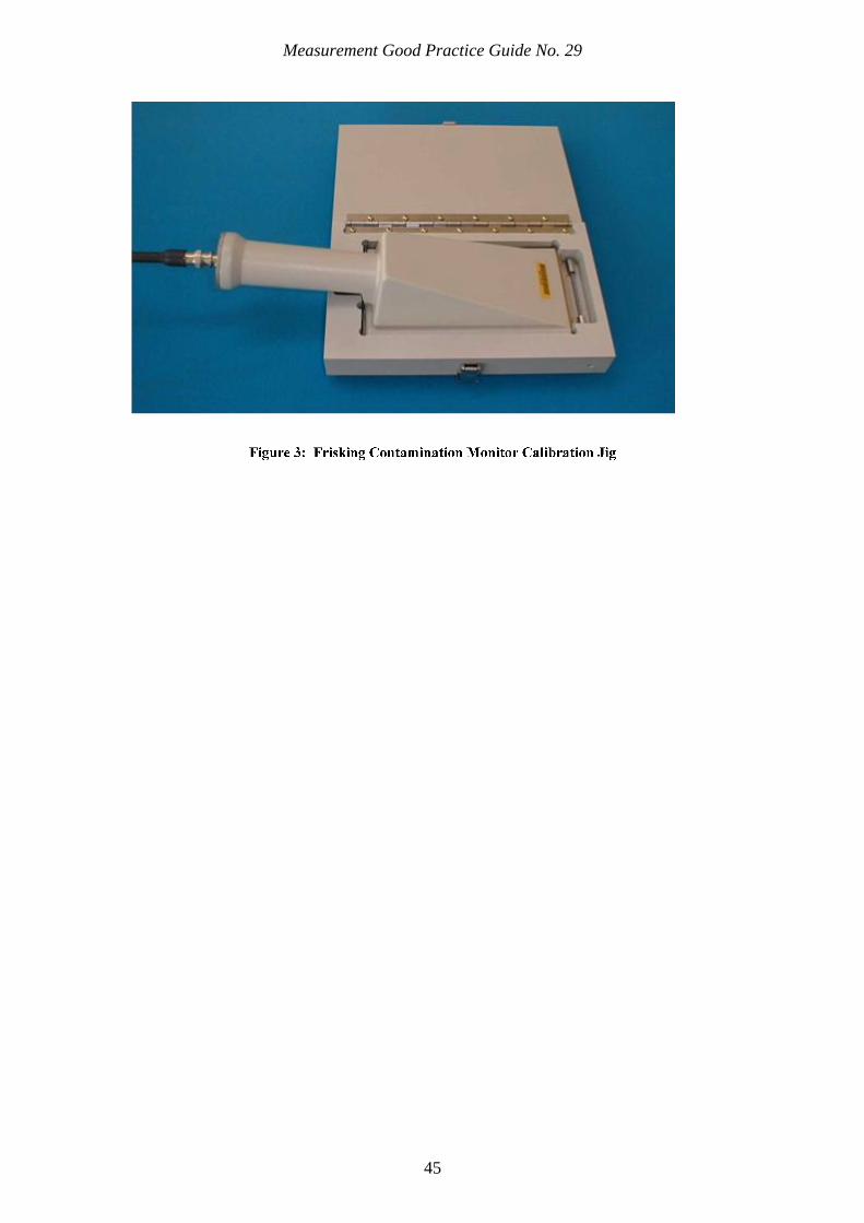
Measurement Good Practice Guide No. 29
45

Measurement Good Practice Guide No. 29
46
Photograph of Isotrak
TM source reproduced with permission of Eckert and Ziegler
Contamination monitor calibration sources will typically be tertiary standards, which
have been compared, not with the primary standard, but with an appropriate secondary
standard. Tertiary standards should be calibrated against a secondary standard at least
every four years and be the subject of at least an intercomparison check every two
years. Causes of deviation from the expected output have included an apparent loss of
activity to the atmosphere, which has occurred with 14
C sources, and examples where
the source was contaminated by another radionuclide of longer half life, where the

Measurement Good Practice Guide No. 29
47
effects were initially insignificant, but which become more important as the primary
nuclide decays.
The testing of workplace portal monitors generally involves the placing of sources of
specified radionuclide and activity in a defined position or positions. As such, it is the
effective activity of the sources which is important. There is a variety of mechanisms
for the measurement of effective activity. One mechanism particularly suitable for
lower activity sources involves the comparison with a suitable traceable source of the
same nuclide using an appropriate detector, such as an HPGe detector or a sodium
iodide scintillator, identifying that only the expected photopeak or peaks are present
and then comparing the photopeak count rates.
For higher activity sources, an alternative option is to measure the dose rate produced
by the source at a defined distance in low scatter conditions using a detector which has
a known response at the energy of interest. The measured dose rate can then be used to
calculate the effective activity using the specific gamma ray constant13
.
Low scatter conditions can be assured by mounting the source and detector on low
mass supports and ensuring that the source to detector centre distance is much less
than the distance from either element to floors or walls.
It is essential that the source to detector distance is at least 3 detector maximum
dimensions (depth or diameter). This allows the detector to be treated as a point
detector at its geometric centre with only minimal error.
The equipment can be quite simple. An ionisation chamber and electrometer can be
used, where the source activity is sufficient to generate a current with an acceptable
uncertainty when corrected for temperature, pressure and leakage. In many cases, an
energy compensated GM detector connected to a scaler timer is effective. These have
the merit of not requiring temperature and pressure correction and of generally being
more sensitive per unit volume. This allows the source to be mounted closer to the
detector. The statistical treatment of the results is also easier in the sense that it is
defined by the background count rate, the source count rate and the relevant measuring
times. No matter which method is used, the equipment employed must have a suitable
calibration traceable to national standards.
48
Certification of Tests
IN THIS CHAPTER
99
Calibration Laboratory
Workplace Testing
Test Label
Measurement Good Practice Guide No. 29
49
The results of tests performed under the current regulations should be communicated to
the Employer in a formal manner. The precise format of a test certificate or report is not
specified in the regulations and may depend on where the calibration or test takes place
and who it is performed by. In many instances, installed radiation protection equipment
is tested and calibrated by the Employer in the workplace and it may not be appropriate
to produce a formal certificate or report so long as an adequate record is made. Any
requirements relating to the record or production of a certificate or report should be
specified by the Employer‟s Radiation Protection Adviser. It is recommended where the
testing is performed by a Test House which is not the Employer, a formal certificate is
produced. If an instrument fails to meet the pass/fail criteria of any component of a test,
the calibration or test laboratory should prominently label the instrument as failed and
make some indication of the nature of the failure on the test document.
The information provided for an installed instrument that is tested in a Calibration
Laboratory or in the workplace by an external Test House is the same as that required for
a portable instrument. The following basic information should be provided by the Test
House:
a) the name and address of the customer or user;
b) a description of the instrument (including type, serial number and unique
identifier);
The intended use of the instrument. Where it is not possible to determine this then the
range over which it has been tested should be specified. For example, for a personnel
contamination, a suitable phrase may be “Monitoring of personnel for alpha and beta
surface contamination for radionuclides with a maximum energy in excess of 150 keV”.
c) the type of test, i.e. TBFU, Periodic Test or Retest After Repair;
d) any limitations of the calibration performed including identification of
the output modes or ranges not tested;
e) a basic description of the test, any specific instrument settings used
which may be readily modified by the user, any significant deviations
from the manufacturers recommended settings and any adjustments or
repairs performed;
f) the results of the tests including a statement of the uncertainty with the

Measurement Good Practice Guide No. 29
50
confidence level at which the uncertainty is quoted for numerical results;
g) a record of the background dose rate or count rate and any relevant
environmental conditions during the tests;
h) the value of the dose rate used for the high dose rate test or activity used
for the high activity source test;
i) the value of any conversion coefficient or P-factor applied to the results;
j) a statement that the test was carried out for the purpose of the
regulations and was successful or the test criteria were met;
k) the name and signature of the QP responsible for the test;
l) the name, address and contact details of the laboratory at which the test
was performed;
m) the date of the test;
n) the test certificate reference number.
In addition to the information listed above, further details should be provided when
surface contamination monitors have been calibrated. The sizes of the calibration sources
used for the determination of alpha, beta or photon response and the orientation in which
they were used with respect to the source should be indicated. Where a contiguous
portions measurement has been made, the value of any correction factor used should be
clearly stated.
The results of Periodic or Routine tests for an installed instrument do not typically require
the issue of a certificate for each instrument. However the Test House should indicate all
the information listed above through a combination of documented test procedures that
describe the tests to be undertaken and a test record which provides the information that
is unique to the instrument. In general the record should specify as a minimum the
following:
a) Location of the instrument;
b) Type and serial number of the instrument;
Measurement Good Practice Guide No. 29
51
c) Type of test e.g. Routine or Periodic;
d) a basic description of the test, any specific instrument settings used which may
be readily modified by the user, any significant deviations from the
manufacturers recommended settings and any adjustments or repairs
performed;
e) Results of the testing, including background indications;
f) Name and signature of QP responsible for the test.
As test reports are usually filed away for quality assurance purposes and tend not to
accompany instruments in the workplace, it is recommended that instruments which are
satisfactory are labelled after Test before First Use and Periodic testing: with the
following information
a) unique identifier of the instrument;
b) the date of calibration or test;
c) test reference (where the test is performed in a Calibration Laboratory or by an
external Test House).
If an instrument fails to meet the pass/fail criteria of any component of a test, the Test
House should prominently label the instrument as failed and make some indication of the
nature of the failure on the certificate, test report or other record. Where testing is
performed in the workplace it is especially important that the Test House indicates to
both the Employer and the user that the instrument is not fit for use.
Measurement Good Practice Guide No. 29
52
Quantities and Units
IN THIS CHAPTER
1100
Quantities and Units
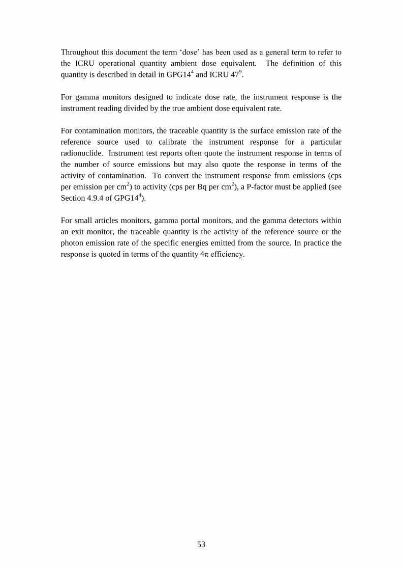
53
Throughout this document the term „dose‟ has been used as a general term to refer to
the ICRU operational quantity ambient dose equivalent. The definition of this
quantity is described in detail in GPG144 and ICRU 47
9.
For gamma monitors designed to indicate dose rate, the instrument response is the
instrument reading divided by the true ambient dose equivalent rate.
For contamination monitors, the traceable quantity is the surface emission rate of the
reference source used to calibrate the instrument response for a particular
radionuclide. Instrument test reports often quote the instrument response in terms of
the number of source emissions but may also quote the response in terms of the
activity of contamination. To convert the instrument response from emissions (cps
per emission per cm2) to activity (cps per Bq per cm
2), a P-factor must be applied (see
Section 4.9.4 of GPG144).
For small articles monitors, gamma portal monitors, and the gamma detectors within
an exit monitor, the traceable quantity is the activity of the reference source or the
photon emission rate of the specific energies emitted from the source. In practice the
response is quoted in terms of the quantity 4π efficiency.

Measurement Good Practice Guide No. 29
54
Definitions
IN THIS CHAPTER
1111
Definitions
55
Ambient
(as applied to dose rate,
etc)
The normal background condition in the absence of any
artificial source of ionising radiation.
Backscatter The deflection of radiation or nuclear particles by scattering
processes through angles greater than 90° with respect to
the original direction of travel.
Baseline Data Test results (usually from a Periodic Test performed around
the time of installation of an instrument) against which all
future results of Periodic Tests and some Tests After Repair
will be compared. After significant repairs it may be
appropriate to redefine the baseline data. To be defined from
2.2 and 2.6.
Detection Efficiency The ratio between the observed count rate and the surface
emission rate of the source, expressed as a percentage.
Detector Fail Alarm
Low Level Alarm
An alarm that is activated when the pulse rate or current from
the detector falls below a certain level. Typically this alarm
will be activated by a failure of the detector or by damage to
the cabling between the detector and the processing unit of the
instrument. Historically, the term Low Level Alarm has been
used by some manufacturers to describe this function.
These operate at decreasing dose rate and generally act as an
additional fault alarm but could be used for process control.
Dual Probe
A radiation detector probe which can be used to make
independent measurements of two different types of
radiation e.g. alpha and beta.
Employer The person or establishment who is legally responsible for the
maintenance of the equipment.
Energy Compensated
(as applied to detectors)
The process of adjusting the response characteristic of a
detector system such that the measured response is
relatively independent of the energy of the radiation over an
identified range.
Fold-back
The behaviour of a detector system whereby the indication
reduces as the radiation intensity increases. In extreme
cases, the indication may drop to zero at very high exposure
rates.
Function-check Source An uncalibrated source which causes the detector to
indicate a response above background. Often used to test
Measurement Good Practice Guide No. 29
56
such items as alarm level settings, etc.
Priming Source A radioactive source, which is incorporated into the
instrument and is in close proximity to the detector. The
instrument measuring assembly will receive a constant signal
from the detector, which is above a typical background signal.
When the pulse rate from the detector drops below a
predefined level, this will initiate a low level fail alarm.
Qualified Person (QP)
A person who possesses the necessary expertise in
instrumentation, theory and practice appropriate to the
instrumentation to be tested. This person may have
responsibility for developing test protocols, taking account of
the intended use of the instrumentation, as stated by the
Employer.
Self-absorption The absorption of the ionising radiation emitted from a
radioactive source by the source material itself.
Specific Activity The activity of a given radionuclide per unit mass.
Sum Zone A pseudo detector that utilises the sum of the counts from 2
or more physical detectors. Alarm thresholds may be set for a
sum zone, in a similar way as for a single detector. Many
small articles monitors use a sum zone which is the sum of
counts from all detectors.
Test House This indicates the organisation undertaking the testing of the
instrument. This may include: an independent calibration
laboratory; a contract company who undertake the instrument
testing in the workplace; or a department under direct
management control of the Employer who undertakes testing
in the laboratory or in the workplace. Ideally the Test House
should may UKAS accreditation for all the testing that it
undertakes.
Time Constant
(of an instrument
response)
A measure of the time before the indicated response of an
instrument reaches a given percentage of true response
(often taken as 90%).
Traceability
The property of a result of a measurement whereby it can be
related to appropriate standards, generally international or
national standards, through an unbroken chain of
comparisons.
57
Appendix A:
Workplace Testing of a
Gamma Monitor

Measurement Good Practice Guide No. 29
58
On plant radiation tests on a gamma monitor benefit from the use of a test jig. This is
especially true for the high dose rate test. A well designed test jig will have the dual
benefit of providing a reproducible geometry for the tests and minimising the doses to
the Test House operator. Where the Employer owns more than one gamma monitor of
the same type, he should consider the design or purchase a test jig.
The components of a typical jig are:
1. A shielded source container
2. A suitable radiation source
3. A means of moving the source from the container to the exposure position
4. A collimator which defines the source position and limits the beam to that
which is useful
5. A means of mounting the collimator at a defined distance or distances and
orientation
6. A series of absorbers which can be used to change the dose rate without
having to house the source or move the collimator
A convenient means is to use an industrial radiography exposure unit.
The reference dose rate from such a source can be derived by determining the
indication with the source in position, in the jig, and then using conventional test
facilities to measure the true dose rate to which that corresponds. This effectively
makes the instrument used a tertiary standard. Note that the reference dose rate will
need to be determined for each instrument type (because of variations in detector size
and position within instruments). The reference dose rate should then be corrected for
radioactive decay using the appropriate half life. In most cases, 137
Cs is appropriate for
this test as it offers a reasonable dose rate per unit activity, a convenient half life and
an energy which is sufficient to penetrate instrument cases but can still be shielded
with reasonable collimator thickness.
In some situations, it may be impractical to manufacture a test jig. For example where
the accessibility of the monitor is poor, or where the monitor is of an unusual one-off
design. In such situations, the Test House may choose to use a hand held source,
normally incorporated into a rod. The Employer and the Test House should ensure
that the doses to the operator are as low as reasonably practicable (ALARP), especially
where the activity of the test sources is in excess of the equivalent of 1 MBq of 137
Cs.
For the high dose rate test, a dose rate indication of the order of 10 mSv h-1
is required.
This dose rate would be achieved by a projector style exposure unit, containing a
source of at least 10 MBq of 137
Cs, which is available from a number of
manufacturers. This unit has the additional benefits of clearly showing when the
source is exposed, and will include some radiation interlocks. A typical unit will be
portable with a mass of approximately 10 kg.
Measurement Good Practice Guide No. 29
59
Where a high dose rate is not required, a lightweight unit incorporating a less
penetrating radionuclide source may suffice. Such a unit would utilise the 60 keV
photon emissions from an 241
Am source. A source with an activity less than 1 GBq
should provide dose rates up to 1 mSv h-1
to the detector. The test radionuclide is
especially useful for uncompensated GM detectors where the response of the detector
to 60 keV photons is considerably greater than that of a compensated detector. Due to
the low penetration of 60 keV photons, the unit will require a minimum of shielding
and should therefore be hand held with a mass of the order of 0.5 kg. However the
Employer and the Test House should ensure that the gamma monitor detectors have a
reasonable response to low energy photons, before utilising such a device. Stainless
steel housed detectors may have a poor response to such a test jig.
The required source activity can be calculated from the detector dimensions and the
maximum dose rate required. Good practice is to place the source at 3 times the
largest dimensions of the detector. Under these conditions, the detector will follow the
inverse square law with sufficient accuracy. However, for large detectors, this is
impractical, as it would lead to an inconveniently high source activity. Therefore
testing often takes place with the source much closer, and sometimes touching the
detector. There are two problems with this:
It is difficult to predict the average dose rate in the detector.
The average dose rate is very sensitive to source position.
The first problem can be addressed before installation. An example of the instrument
type should be used to determine the apparent dose rate versus distance curve. This
can then be used to derive an expected indication from the test source.
The second problem requires that the source position is sensible, i.e. not in a position
where, for example, it is partially shielded which will generate large variations in
indication for small source movements. It also requires that the position is fixed with
respect to the instrument. This can be achieved in a variety of ways, such as gluing the
source holder to the instrument case, or fixing it to the wall alongside the instrument,
or the use of a jig specific to the detector type and geometry.
Instruments are often mounted on a wall, which will produce backscatter when
exposed to gamma radiation. This should be allowed for in the in situ testing process.
The effect of backscatter will be type specific and should not vary from example to
example of the same type. All that is required is to use the test sources with the
detector in free air and then to repeat the measurements with the detector on a suitable
wall. Thick concrete typically generates about 6% backscatter, thinner materials are
less effective.

Measurement Good Practice Guide No. 29
60
Alternative methods for conducting this test use work in progress as either the source
of radiation where there is sufficient accuracy in the activity, or in combination with a
transfer standard. Where a transfer instrument is used, it can be mounted alongside the
instrument under test. This reference instrument can be a very low sensitivity GM
detector attached to a relatively simple rate meter, which has been calibrated before
any testing campaign over the range of dose rates expected. Again, it may not be
possible to make measurements over the full possible dose rate range, but if the
function of the installed instrument can be confirmed up to the point where, for
example, any overload trigger operates, then that will give reasonable confidence that
the system is operating correctly.
Where the activity of the source used during the work in progress is known with
sufficient accuracy, one of the sources can be brought close enough to the detector in
question to perform the test. There are limitations with this, in that a close approach to
a large detector produces very non-uniform detector irradiation and makes it difficult
to calculate the reference value. If this approach is to be used, the dose versus distance
curve should be established before the detector is installed.
Finally, where an instrument is used within a cell where x-radiations are used, the kV
and current that just produces full scale indication on the monitor can be determined.
These values can then be used to generate a reference indication before and after each
full output test.
61
Appendix B:
Directional Dependence
Testing of a
Gamma Monitor
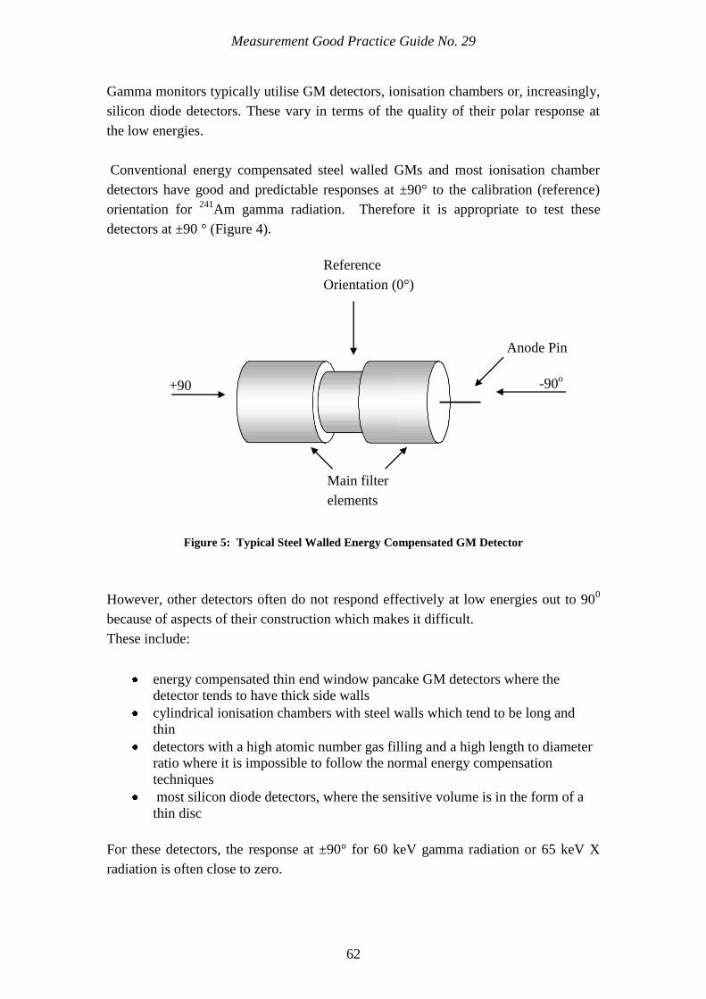
Measurement Good Practice Guide No. 29
62
Gamma monitors typically utilise GM detectors, ionisation chambers or, increasingly,
silicon diode detectors. These vary in terms of the quality of their polar response at
the low energies.
Conventional energy compensated steel walled GMs and most ionisation chamber
detectors have good and predictable responses at ±90° to the calibration (reference)
orientation for 241
Am gamma radiation. Therefore it is appropriate to test these
detectors at ±90 ° (Figure 4).
Figure 5: Typical Steel Walled Energy Compensated GM Detector
However, other detectors often do not respond effectively at low energies out to 900
because of aspects of their construction which makes it difficult.
These include:
energy compensated thin end window pancake GM detectors where the
detector tends to have thick side walls
cylindrical ionisation chambers with steel walls which tend to be long and
thin
detectors with a high atomic number gas filling and a high length to diameter
ratio where it is impossible to follow the normal energy compensation
techniques
most silicon diode detectors, where the sensitive volume is in the form of a
thin disc
For these detectors, the response at ±90° for 60 keV gamma radiation or 65 keV X
radiation is often close to zero.
GM +90
Anode Pin
Reference
Orientation (0°)
Main filter
elements
-90o
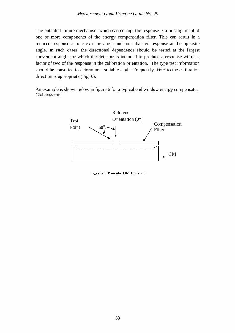
Measurement Good Practice Guide No. 29
63
The potential failure mechanism which can corrupt the response is a misalignment of
one or more components of the energy compensation filter. This can result in a
reduced response at one extreme angle and an enhanced response at the opposite
angle. In such cases, the directional dependence should be tested at the largest
convenient angle for which the detector is intended to produce a response within a
factor of two of the response in the calibration orientation. The type test information
should be consulted to determine a suitable angle. Frequently, ±60° to the calibration
direction is appropriate (Fig. 6).
An example is shown below in figure 6 for a typical end window energy compensated
GM detector.
Compensation
Filter 60
o
Test
Point
Reference
Orientation (0°)
GM
64
Appendix C:
Check Radionuclides
for Contamination
Monitors in Different
Workplaces
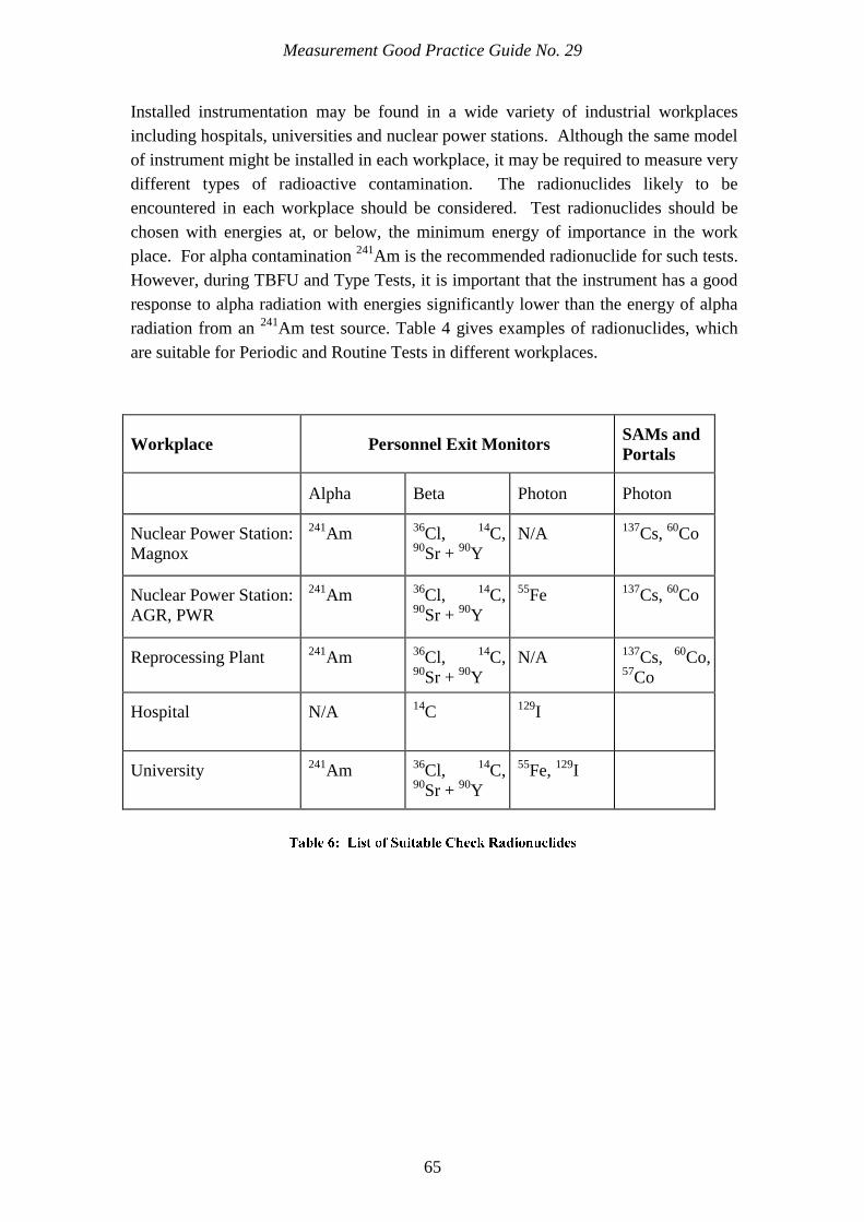
Measurement Good Practice Guide No. 29
65
Installed instrumentation may be found in a wide variety of industrial workplaces
including hospitals, universities and nuclear power stations. Although the same model
of instrument might be installed in each workplace, it may be required to measure very
different types of radioactive contamination. The radionuclides likely to be
encountered in each workplace should be considered. Test radionuclides should be
chosen with energies at, or below, the minimum energy of importance in the work
place. For alpha contamination 241
Am is the recommended radionuclide for such tests.
However, during TBFU and Type Tests, it is important that the instrument has a good
response to alpha radiation with energies significantly lower than the energy of alpha
radiation from an 241
Am test source. Table 4 gives examples of radionuclides, which
are suitable for Periodic and Routine Tests in different workplaces.
Workplace Personnel Exit Monitors SAMs and
Portals
Alpha Beta Photon Photon
Nuclear Power Station:
Magnox
241Am
36Cl,
14C,
90Sr +
90Y
N/A 137
Cs, 60
Co
Nuclear Power Station:
AGR, PWR
241Am
36Cl,
14C,
90Sr +
90Y
55Fe
137Cs,
60Co
Reprocessing Plant 241
Am 36
Cl, 14
C, 90
Sr + 90
Y
N/A 137
Cs, 60
Co, 57
Co
Hospital N/A
14C
129I
University 241
Am 36
Cl, 14
C, 90
Sr + 90
Y
55Fe,
129I

66
References

Measurement Good Practice Guide No. 29
67
1. The Ionising Radiations Regulations, 1999, HMSO, 1999.
2. Work with ionising radiation, approved code of practice, Ionising Radiation
Regulations 1999, HMSO, 1999.
3. National Physical Laboratory, Measurement Good Practice Guide No. 82, The
Examination and Testing of Equipment for Monitoring Airborne Radioactive
Particulate in the Workplace, NPL, 2006.
4. National Physical Laboratory, Measurement Good Practice Guide No.14, The
examination, testing and calibration of portable radiation protection
instruments, NPL, 1999.
5. International Atomic Energy Agency, Calibration of Radiation Protection
Monitoring Instruments, Safety Series No. 16, IAEA, 2000.
6. British Standard, Radiation protection instrumentation. Installed dose rate
meters, warning assemblies and monitors. X and gamma radiation of energy
between 50 keV and 7 MeV, BS IEC 60532, 2010.
7. British Standard, Radiation protection instrumentation. Installed personnel
surface contamination monitoring assemblies, BS EN 61098, 2007.
8. British Standard, Radiation protection instrumentation – Alpha, beta and
alpha/beta (beta energy > 60 keV) contamination meters and monitors,
BS EN 60325, 2004.
9. International Commission on Radiological Units and Measurements, Quantities
and Units in Radiation Protection Dosimetry, ICRU Report 51, 1993.
10. British Standard, Reference sources. Calibration of surface contamination
monitors. Alpha-, beta- and photon emitters, BS ISO 8769, 2010.
11. British Standard, X and gamma reference radiations for calibrating dosemeters
and doserate meters and for determining their response as a function of photon
energy. Radiation characteristics and production methods, BS ISO 4037-1,
1996.
12. Industry Radiological Protection Co-ordination Group, The Selection of Alarm
Levels for Personnel Exit Monitors,

Measurement Good Practice Guide No. 29
68
13. International Commission on Radiological Protection, Nuclear Decay Data for
Dosimetric Calculations, ICRP Publication 107, 2008.


![Lynsey Allan [Type here] Director of Hockey](https://static.fdocuments.net/doc/165x107/617683e4e73d143dc0647670/lynsey-allan-type-here-director-of-hockey.jpg)