Pertanika J. Sci. & Technol. 25 (S): 85 - 92 (2017 ... PAPERS/JST Vol. 25 (S) Apr. 2017/09... ·...
8
Pertanika J. Sci. & Technol. 25 (S): 85 - 92 (2017) SCIENCE & TECHNOLOGY Journal homepage: http://www.pertanika.upm.edu.my/ ISSN: 0128-7680 © 2017 Universiti Putra Malaysia Press. ARTICLE INFO Article history: Received: 25 October 2016 Accepted: 17 March 2017 E-mail addresses: [email protected] (Nor Dalila Nor Affandi), rozitex@[email protected] (Mohd Rozi Ahmad), [email protected] (Sabiha Hanim Saleh), [email protected] (Muhammad Fairuz Remeli), [email protected] (Nur Hayati Humairah Nur Ikhwan Teo), [email protected] (Nurul Farihin Amran) *Corresponding Author A Study on the Formation of PVA/Kenaf Nanofibres via Electrospinning Nor Dalila Nor Affandi 1 *, Mohd Rozi Ahmad 1 , Sabiha Hanim Saleh 1 , Muhammad Fairuz Remeli 2 , Nur Hayati Humairah Nur Ikhwan Teo 1 and Nurul Farihin Amran 1 1 Textile Research Group, Faculty of Applied Sciences, Universiti Teknologi MARA (UiTM), 40450 Shah Alam, Selangor, Malaysia 2 Faculty of Mechanical Engineering, Universiti Teknologi MARA (UiTM), 40450 Shah Alam, Selangor, Malaysia ABSTRACT This paper reports a study of the formation of cellulose nanofibres from kenaf waste using chemical extraction method. The extracted holocellulose was then prepared for acid hydrolysis to form the cellulose. Before mixing it with polyvinyl chloride (PVA) solution and extruded using electrospinning under different parameters to produce PVA/kenaf nanofibres. Results showed that the morphological structures of PVA/kenaf nanofibres varied at different voltages. An increase in voltage from 10 kV to 20 kV produced more beads along the fibre length. In addition, the applied voltages were found to affect the resultant fibre diameter of the PVA/kenaf nanofibres. The results also showed that the electrospinning parameters affect the shapes of the PVA/kenaf nanofibre membranes. Based on the experimental works, the optimal applied voltage was found to be at 15 kV, where the resultant fibre diameter and membrane coverage area were approximately 43.9 ± 3.1 nm and 214.2 ± 15.8 cm 2 , respectively. Keywords: Cellulose, electrospinning, kenaf wastes, morphological structures, nanofibres INTRODUCTION Kenaf (Hibiscus cannabinus) is a natural bast fibre from lignocellulosic source and made up of three major elements, which are the lignin, hemicellulose and cellulose (Reddy & Yang, 2005). The kenaf stem was reported to have the highest cellulose content compared to any other parts of kenaf (Akil et al., 2011). The presence of cellulose gives strength
Transcript of Pertanika J. Sci. & Technol. 25 (S): 85 - 92 (2017 ... PAPERS/JST Vol. 25 (S) Apr. 2017/09... ·...

Pertanika J. Sci. & Technol. 25 (S): 85 - 92 (2017)
SCIENCE & TECHNOLOGYJournal homepage: http://www.pertanika.upm.edu.my/
ISSN: 0128-7680 © 2017 Universiti Putra Malaysia Press.
ARTICLE INFO
Article history:Received: 25 October 2016Accepted: 17 March 2017
E-mail addresses: [email protected] (Nor Dalila Nor Affandi),rozitex@[email protected] (Mohd Rozi Ahmad),[email protected] (Sabiha Hanim Saleh),[email protected] (Muhammad Fairuz Remeli),[email protected](Nur Hayati Humairah Nur Ikhwan Teo),[email protected] (Nurul Farihin Amran) *Corresponding Author
A Study on the Formation of PVA/Kenaf Nanofibres via Electrospinning
Nor Dalila Nor Affandi1*, Mohd Rozi Ahmad1, Sabiha Hanim Saleh1, Muhammad Fairuz Remeli2, Nur Hayati Humairah Nur Ikhwan Teo1 and Nurul Farihin Amran1 1 Textile Research Group, Faculty of Applied Sciences, Universiti Teknologi MARA (UiTM), 40450 Shah Alam, Selangor, Malaysia2Faculty of Mechanical Engineering, Universiti Teknologi MARA (UiTM), 40450 Shah Alam, Selangor, Malaysia
ABSTRACT
This paper reports a study of the formation of cellulose nanofibres from kenaf waste using chemical extraction method. The extracted holocellulose was then prepared for acid hydrolysis to form the cellulose. Before mixing it with polyvinyl chloride (PVA) solution and extruded using electrospinning under different parameters to produce PVA/kenaf nanofibres. Results showed that the morphological structures of PVA/kenaf nanofibres varied at different voltages. An increase in voltage from 10 kV to 20 kV produced more beads along the fibre length. In addition, the applied voltages were found to affect the resultant fibre diameter of the PVA/kenaf nanofibres. The results also showed that the electrospinning parameters affect the shapes of the PVA/kenaf nanofibre membranes. Based on the experimental works, the optimal applied voltage was found to be at 15 kV, where the resultant fibre diameter and membrane coverage area were approximately 43.9 ± 3.1 nm and 214.2 ± 15.8 cm2, respectively.
Keywords: Cellulose, electrospinning, kenaf wastes, morphological structures, nanofibres
INTRODUCTION
Kenaf (Hibiscus cannabinus) is a natural bast fibre from lignocellulosic source and made up of three major elements, which are the lignin, hemicellulose and cellulose (Reddy & Yang, 2005). The kenaf stem was reported to have the highest cellulose content compared to any other parts of kenaf (Akil et al., 2011). The presence of cellulose gives strength

Nor Dalila Nor Affandi, Mohd Rozi Ahmad, Sabiha Hanim Saleh, Muhammad Fairuz Remeli,Nur Hayati Humairah Nur Ikhwan Teo and Nurul Farihin Amran
86 Pertanika J. Sci. & Technol. 25 (S): 85 - 92 (2017)
and firmness to the plant fibres (Paster et al., 2003). Kenaf fibres have gained a great deal of attention because they are readily available, biodegradable, strong, and lightweight (Nishino et al., 2003). The fibres from kenaf can be obtained using several extraction methods such as dew retting, chemical and mechanical extraction. However, these extraction methods can only produce fibres at micron size. To enhance its potential in certain applications, there is a need to convert the microcellulose fibres into nano size cellulosic fibres.
To date, there have been a number of methods to produce nanofibres such as phase separation, template synthesis, self-assembly, drawing, and electrospinning. Electrospinning is reported to be an ideal method since it can produce nanofibres in long and continuous fibre form (Ramakrishna, 2005). There are three stages in electrospinning; which are the starting of jet and elongation of the jet in a direct course, development of bending instability and longer extension of the jet, which enable the jet turn thin and long as it pursues a looping spiral path, and jet hardening to produce nanofibres (Salem, 2001). The product of electrospinning piled up to form a nanofiber membrane (Ramakrishna, 2005).
Nanofibre membrane exhibits a number of outstanding properties such as high surface area per mass compared to bulk fibres and film (Grafe & Graham, 2003; Gopal et al., 2006) and small pore sizes (Gopal et al., 2006). Due to these properties, the membrane has the potential to be employed in liquid or gas filtration (Reneker et al., 2000; Gopal et al., 2006). In liquid filtration applications, the fine pore size of nanofibre membrane has successfully removed microparticles (Gopal et al., 2006). In addition, incorporation of nanofibre membrane with Nafion membrane has been reported to reduce methanol fuel crossover (fuel waste) from anode to cathode while maintaining proton conductivity, compared with uncoated Nafion (Ramakrishna et al., 2006). The application of nanofiber membrane was further diversified when the membrane was observed to exhibit good performance in tissue engineering (Ramakrishna et al., 2006; Gu, Ren, & Vancso, 2005; Casarano et al., 2009). Due to its high surface-to-volume ratio, electrospun membrane was reported to permit cell growth over membrane surfaces, which will generate new tissues (Ramakrishna et al., 2006).
The feasibility of electrospinning to produce fibres at nano-scale has encouraged the researchers to carry out this study. The main purpose of the study is to relate the electrospinning voltage with respect to the morphological aspects of cellulosic kenaf nanofibres.
METHOD
In this study, kenaf wastes were extracted using chemical extraction. The ground kenaf wastes were first dried for 24 hours at 80°C. After that, the dried kenaf wastes were dewaxed using toluene:ethanol (2:1, v/v) for 6 hours. The dewaxed ground kenaf was then prepared for acid-hydrolysis by treating the wastes with 2 M sodium hydrogen chloride (HCl) at 80°C for 2 hours. Next, the kenaf wastes were treated with sodium hydroxide (NaOH) for 2 hours at 80°C and further treated with hydrogen peroxide (H2O2) at room temperature for 5 hours. Finally, the kenaf wastes were washed with distilled water and dried at 60°C to obtain cellulose.
The kenaf cellulose was then mixed with 10% w/w PVA solution to form PVA/kenaf cellulose solution. The mixing was done at room temperature under continuous agitation. The PVA solution was prepared by dissolving PVA powder (Sigma-Aldrich, Mw 125,000 g/mol)

Formation of PVA/Kenaf Nanofibres via Electrospinning
87Pertanika J. Sci. & Technol. 25 (S): 85 - 92 (2017)
in distilled water at 80°C for 3 hours. The preparation of the PVA/kenaf cellulose solution was adapted from a previous study (Sutka et al., 2014).
The formation of PVA/kenaf nanofibres was carried out using an electrospinning equipment (Figure 1). A single nozzle spinneret with a 23G (Ø0.65 mm) needle was used to electrospin the PVA/kenaf solution at different applied voltages ranging from 10 kV to 20 kV with an electropinning distance of 10 cm. The solution was pumped at a constant feed rate (0.2 ml/h) using a syringe pump. The electrospinning was carried out at room temperature with relative humidity ranging from 40 to 60%. The PVA/kenaf nanofibres were deposited on grounded aluminium foil for 3 minutes with positive polarity at the needle tip. An optimal electrospinning parameter for PVA/kenaf nanofibre membranes was based on large membrane area. The resultant PVA/kenaf nanofibres were characterised for morphological structures, membrane coverage area and Fourier Transform Infrared Spectroscopy (FTIR) analysis.
Figure 1. A schematic diagram of the electrospinning system used in the study
RESULTS AND DISCUSSION
Figure 2(a) illustrates the morphological structures of PVA nanofibres. The PVA
nanofibres have long, continuous, uniform, and cylindrical shape of fibres. The
morphological structures of the PVA were found to change when kenaf cellulose was
added into the PVA solution. As shown in Figures 2(b) to (d), beads are formed along the
length of PVA/kenaf nanofibres. A possible reason of this is the poor chain entanglement
between the PVA and cellulose. This poor chain entanglement resulted in beaded fibres
rather than uniform and continuous fibres.
It was also found that more beads were formed when the voltage increased from 10kV
to 20kV (Figure 2(b) to (d)). This phenomena has been described by Fong, Chun and
Reneker (1999), who reported that the increase of voltage caused the electrospinning jets
to hit the internal needle wall and form more beaded fibres.
Figure 1. A schematic diagram of the electrospinning system used in the study
RESULTS AND DISCUSSION
Figure 2(a) illustrates the morphological structures of PVA nanofibres. The PVA nanofibres have long, continuous, uniform, and cylindrical shape of fibres. The morphological structures of the PVA were found to change when kenaf cellulose was added into the PVA solution. As shown in Figures 2(b) to (d), beads are formed along the length of PVA/kenaf nanofibres. A possible reason of this is the poor chain entanglement between the PVA and cellulose. This poor chain entanglement resulted in beaded fibres rather than uniform and continuous fibres.
It was also found that more beads were formed when the voltage increased from 10kV to 20kV (Figure 2(b) to (d)). This phenomena has been described by Fong, Chun and Reneker (1999), who reported that the increase of voltage caused the electrospinning jets to hit the internal needle wall and form more beaded fibres.

Nor Dalila Nor Affandi, Mohd Rozi Ahmad, Sabiha Hanim Saleh, Muhammad Fairuz Remeli,Nur Hayati Humairah Nur Ikhwan Teo and Nurul Farihin Amran
88 Pertanika J. Sci. & Technol. 25 (S): 85 - 92 (2017)
Figure 3 shows the average fibre diameter of PVA/kenaf nanofibres at different applied voltages. The fibre diameter of nanofibres was found to increase from 24.2 ± 5.8 nm to 166.1 ± 11.9 nm as the applied voltage increased from 10 kV to 20 kV. By increasing the voltage, more solution was removed from the capillary tip, and this resulted in a bigger fibre diameter. The results agree with a previous study done by Ojha et al. (2008), who reported that the increase of applied voltage produced bigger fibre diameter.
(a) (b)
(c) (d)
Figure 2. Typical SEM images of nanofibers: (a) PVA; (b) PVA/kenaf nanofibres at 10
kV; (c) PVA/kenaf nanofibres at 15 kV; and (d) PVA/kenaf nanofibres at 20 kV
Figure 3 shows the average fibre diameter of PVA/kenaf nanofibres at different
applied voltages. The fibre diameter of nanofibres was found to increase from 24.2 + 5.8
nm to 166.1 + 11.9 nm as the applied voltage increased from 10 kV to 20 kV. By
increasing the voltage, more solution was removed from the capillary tip, and this resulted
in a bigger fibre diameter. The results agree with a previous study done by Ojha et al.
(2008), who reported that the increase of applied voltage produced bigger fibre diameter.
Figure 2. Typical SEM images of nanofibers: (a) PVA; (b) PVA/kenaf nanofibres at 10 kV; (c) PVA/kenaf nanofibres at 15 kV; and (d) PVA/kenaf nanofibres at 20 kV
Figure 3. Fibre diameter versus applied voltage for PVA/kenaf nanofibres
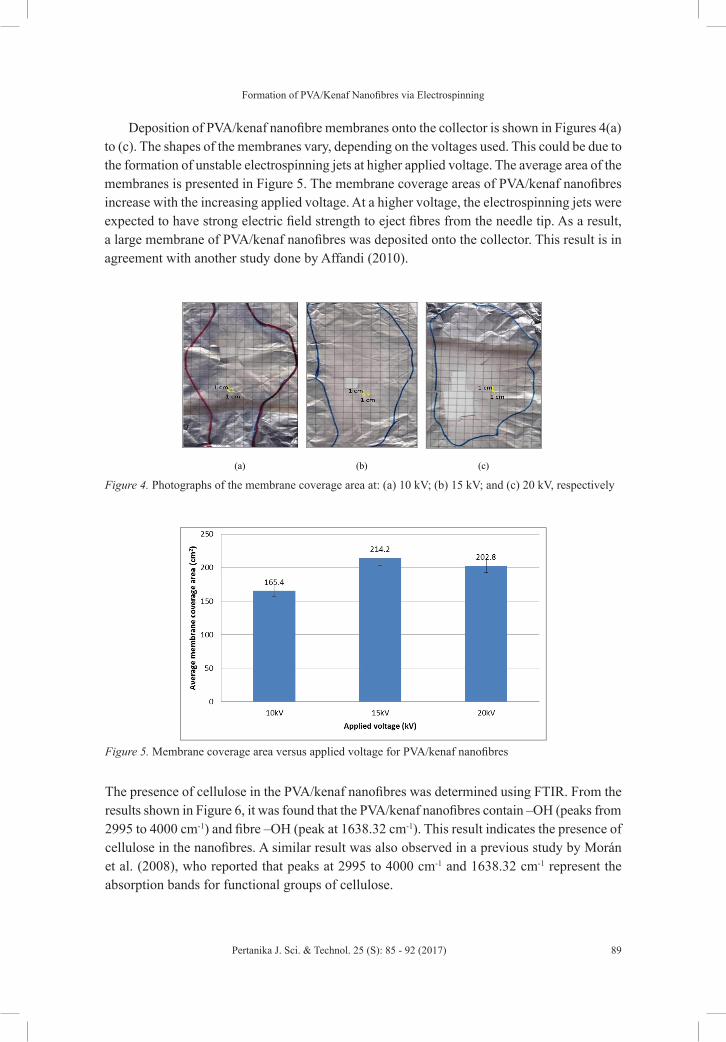
Deposition of PVA/kenaf nanofibre membranes onto the collector is shown in Figures
4(a) to (c). The shapes of the membranes vary, depending on the voltages used. This could
be due to the formation of unstable electrospinning jets at higher applied voltage. The
average area of the membranes is presented in Figure 5. The membrane coverage areas of
PVA/kenaf nanofibres increase with the increasing applied voltage. At a higher voltage,
the electrospinning jets were expected to have strong electric field strength to eject fibres
from the needle tip. As a result, a large membrane of PVA/kenaf nanofibres was deposited
onto the collector. This result is in agreement with another study done by Affandi (2010).
Figure 3. Fibre diameter versus applied voltage for PVA/kenaf nanofibres
Formation of PVA/Kenaf Nanofibres via Electrospinning
89Pertanika J. Sci. & Technol. 25 (S): 85 - 92 (2017)
Deposition of PVA/kenaf nanofibre membranes onto the collector is shown in Figures 4(a) to (c). The shapes of the membranes vary, depending on the voltages used. This could be due to the formation of unstable electrospinning jets at higher applied voltage. The average area of the membranes is presented in Figure 5. The membrane coverage areas of PVA/kenaf nanofibres increase with the increasing applied voltage. At a higher voltage, the electrospinning jets were expected to have strong electric field strength to eject fibres from the needle tip. As a result, a large membrane of PVA/kenaf nanofibres was deposited onto the collector. This result is in agreement with another study done by Affandi (2010).
(a) (b) (c)
Figure 4. Photographs of the membrane coverage area at: (a) 10 kV; (b) 15 kV; and (c) 20
kV, respectively
Figure 5. Membrane coverage area versus applied voltage for PVA/kenaf nanofibres
The presence of cellulose in the PVA/kenaf nanofibres was determined using FTIR.
From the results shown in Figure 6, it was found that the PVA/kenaf nanofibres contain –
Figure 4. Photographs of the membrane coverage area at: (a) 10 kV; (b) 15 kV; and (c) 20 kV, respectively
(a) (b) (c)
Figure 4. Photographs of the membrane coverage area at: (a) 10 kV; (b) 15 kV; and (c) 20
kV, respectively
Figure 5. Membrane coverage area versus applied voltage for PVA/kenaf nanofibres
The presence of cellulose in the PVA/kenaf nanofibres was determined using FTIR.
From the results shown in Figure 6, it was found that the PVA/kenaf nanofibres contain –
Figure 5. Membrane coverage area versus applied voltage for PVA/kenaf nanofibres
The presence of cellulose in the PVA/kenaf nanofibres was determined using FTIR. From the results shown in Figure 6, it was found that the PVA/kenaf nanofibres contain –OH (peaks from 2995 to 4000 cm-1) and fibre –OH (peak at 1638.32 cm-1). This result indicates the presence of cellulose in the nanofibres. A similar result was also observed in a previous study by Morán et al. (2008), who reported that peaks at 2995 to 4000 cm-1 and 1638.32 cm-1 represent the absorption bands for functional groups of cellulose.

Nor Dalila Nor Affandi, Mohd Rozi Ahmad, Sabiha Hanim Saleh, Muhammad Fairuz Remeli,Nur Hayati Humairah Nur Ikhwan Teo and Nurul Farihin Amran
90 Pertanika J. Sci. & Technol. 25 (S): 85 - 92 (2017)
CONCLUSION
The PVA/kenaf cellulose solutions were successfully extruded using electrospinning. The results showed that the formation of beaded fibres was influenced by the voltage applied. The increase in the voltages from 10 kV to 20 kV produced more beads along the fibre length. In addition, the electrospinning parameters had significantly affected fibre diameter. The resultant fibre diameter was observed to increase from 24.2 ± 5.8 nm to 166.1 ± 11.9 nm when the voltage applied was increased from 10 kV to 20 kV. The results also showed that the voltage applied affected the shapes of the PVA/kenaf nanofibre membranes. Among the variation of the applied voltages used in electrospinning, the voltage of 15 kV was found to be the optimal electrospinning conditions to electrospin PVA/kenaf nanofibres. At 15 cm, the PVA/kenaf nanofibres formed a large membrane coverage area with approximately 214.2 ± 15.8 cm2, respectively.
ACKNOWLEDGEMENTS
The authors would like to acknowledge the Institute of Research Management and Innovation (IRMI), Universiti Teknologi MARA (UiTM), for providing the research funding under LESTARI Grant (Project Number: 600-RMI/DANA 5/3/LESTARI (65/2015)). The authors are also thankful to Dr. Khairunnadim Ahmad Sekak and his research team for assisting with the electrospinning setup.
REFERENCESAffandi, N. D. N. (2010). Studies on fabrication, morphology and performances of bi-layer electrospun
nanofibre membranes (Doctoral dissertation). Retrieved from RMIT University.
Akil, H. M., Omar, M. F., Mazuki, A. A. M., Safiee, S., Ishak, Z. A. M., & Abu Bakar, A. (2011). Kenaf fiber reinforced composites: A review. Materials and Design, 32(8–9), 4107–4121.
Casarano, R., Bentini, R., Bueno, V.B., Lacovella, T., Monteiro, F. B. F., Iha, F. A. S., Campa, A., Petri, D. F. S., Jaffe, M. & Catalani, L. H. (2009). Enhanced fibroblast adhesion and proliferation on electrospun fibers obtained from poly(isosorbide succinate-b-L-lactide) block copolymers. Polymer, 50, 6218-27.
OH (peaks from 2995 to 4000 cm-1) and fibre –OH (peak at 1638.32 cm-1). This result
indicates the presence of cellulose in the nanofibres. A similar result was also observed in
a previous study by Morán et al. (2008), who reported that peaks at 2995 to 4000 cm-1 and
1638.32 cm-1 represent the absorption bands for functional groups of cellulose.
Figure 6. IR spectra for cellulose in PVA/kenaf nanofibres
CONCLUSION
The PVA/kenaf cellulose solutions were successfully extruded using electrospinning. The
results showed that the formation of beaded fibres was influenced by the voltage applied.
The increase in the voltages from 10 kV to 20 kV produced more beads along the fibre
length. In addition, the electrospinning parameters had significantly affected fibre
diameter. The resultant fibre diameter was observed to increase from 24.2 + 5.8 nm to
166.1 + 11.9 nm when the voltage applied was increased from 10 kV to 20 kV. The results
also showed that the voltage applied affected the shapes of the PVA/kenaf nanofibre
Figure 6. IR spectra for cellulose in PVA/kenaf nanofibres

Formation of PVA/Kenaf Nanofibres via Electrospinning
91Pertanika J. Sci. & Technol. 25 (S): 85 - 92 (2017)
Fong, H., Chun, I., & Reneker, D. H. (1999). Beaded nanofibers formed during electrospinning. Polymer, 40(16), 4585-92.
Grafe, T., & Graham, K. (2003). Polymeric nanofibers and nanofiber webs: a new class of nonwovens, Nonwoven Technology Review, 51–5.
Gopal, R., Kaur, S., Ma, Z., Chan, C., & Ramakrishna, S. (2006). Electrospun nanofibrous filtration membrane, Journal of Membrane Science, 281, 581-86.
Gu, S. Y., Ren, J., & Vancso, G. J. (2005). Process optimization and empirical modeling for electrospun polyacrylonitrile (PAN) nanofiber precursor of carbon nanofibers, European Polymer Journal, 41, 2559-68.
Morán, J. I., Alvarez, V. A., Cyras, V. P., & Vázquez, A. (2008). Extraction of cellulose and preparation of nanocellulose from sisal fibers. Cellulose, 15(1), 149–159.
Nishino, T., Hirao, K., Kotera, M., Nakamae, K., & Inagaki, H. (2003). Kenaf reinforced biodegradable composite. Composites Science and Technology, 63(9), 1281–86.
Ojha, S. S., Afshari, M, Kotek, R., & Gorga, R. (2008) Morphology of electrospun nylon-6 nanofibers as a function of molecular weight and processing parameters. Journal of Applied Polymer Science, 108(1), 308-19.
Paster, M., Pellegrino, J. L., & Carole, T. M. (2003). Industrial bioproducts; today and tomorrow. In Industrial bioproducts; today and tomorrow. Energetics Inc.
Ramakrishna, S. (2005). An Introduction to Electrospinning and Nanofibers. World Scientific.
Ramakrishna, S., Fujihara, K., Teo, Wee-Eong., Yong, T., Ma, Z., & Ramakrishna, R. (2006). Electrospun nanofibers: solving global issues. Materials Today, 9, 40-50.
Reddy, N., & Yang, Y. (2005). Biofibers from agricultural by-products for industrial applications. TRENDS in Biotechnology, 23(1), 22–27.
Reneker, D. H, Yarin, A. L., Fong, H., & Koombhongse, S. (2000). Bending instability of electrically charged liquid jets of polymer solutions in electrospinning, Journal of Applied Physics, 87, 4531.
Salem, D. R. (2001). Structure Formation in Polymeric Fibers. Hanser.
Sutka, A., Kukle, S., Gravitis, J., Milašius, R., & Malašauskiene, J. (2014) Electro-spinning Derived Cellulose-PVA Composite Nano-fibre Mats. FIBRES AND TEXTILES in Eastern Europe, 3(105), 43-46.