
PERMISSIBLE LOADING OF GENERATORS AND · PDF fileFACILITIES INSTRUCTIONS, STANDARDS, AND...
19
FACILITIES INSTRUCTIONS, STANDARDS, AND TECHNIQUES Volume 1-4 PERMISSIBLE LOADING OF GENERATORS AND LARGE MOTORS Internet Version of This Manual Created July 2000 The appearance of the Internet Version of This Manual May Differ From the Original, but the Contents Do Not FACILITIES ENGINEERING BRANCH DENVER OFFICE DENVER, COLORADO UNITED STATES DEPARTMENT OF THE INTERIOR BUREAU OF RECLAMATION REVISED MARCH 1991
-
Upload
truongkhanh -
Category
Documents
-
view
214 -
download
0
Transcript of PERMISSIBLE LOADING OF GENERATORS AND · PDF fileFACILITIES INSTRUCTIONS, STANDARDS, AND...
FACILITIES INSTRUCTIONS, STANDARDS,AND TECHNIQUES
Volume 1-4
PERMISSIBLE LOADING OFGENERATORS AND LARGE MOTORS
Internet Version of This Manual Created July 2000
The appearance of the Internet Version of This Manual May Differ From the Original, but the Contents Do Not
FACILITIES ENGINEERING BRANCH DENVER OFFICE
DENVER, COLORADO
UNITED STATES DEPARTMENT OF THE INTERIORBUREAU OF RECLAMATION
REVISED MARCH 1991
Purpose and Scope
This volume is intended to fill the need for practical information concerning the temperature and mechanical and electrical overload limits of rotating electric equipment such as generators and large motors. Rotating electrical equipment cannot be overloaded on the same basis as transformers and is not as able to stand short-time overloads. This is largely because equipment cooled by air does not have the heat transfer ability which the higher thermal conductivity of insulating oil gives to transformers; also, the windings in rotating equipment are confined in slots in the steel and are subject to temperature expansion problems. For any abnormal loading of generators, the electrical, mechanical, and thermal characteristics must be evaluated to determine the machines limitations. Machines should not be loaded beyond the manufacturer's defined overload capability unless a complete study of the unit has been made to define safe limits. Additional tests might have to be conducted to substantiate the possibilities for higher-than-rated loadings.

CONTENTS
Paragraph Page
1. Types of insulation used on rotating machines, their insulation life,
and deterioration causes .........………..................... .....................................................1
1.1 Thermoplastic (asphalt-mica) ………………..…………………….………………………1
1.2 Thermosetting (polyester-mica or epoxy-mica) ……..………….……………………..…1
2. Mechanical limitations .....................………..................................................................1
3. Damage caused by expansion of copper ………………………...…………………………2
4. Limiting temperatures for insulation ……………….………………..……………………….2
5. Hottest spot allowance ……………………………...…………………………………………3
6. Limiting temperature rise …………………………..…………………………………………3
7. Operation of machines under warranty …………..…………………………………………3
8. Operation up to rated capacity …………………..…………………………………………..3
9. Short-time and emergency overloads……………..……………………………..…..……..7
10. Load limitations of associated equipment ..………..……………………………….......…8
11. Cooling water ................................................…................................…........………….8
12. Cooling water regulation…………………..……………………………….………………….8
13. Supplemental cooling ……...………………………………..…………………..…………….9
14. Keeping machines clean …….....……….……………………………………………………9
15. Temperature of old machines …………....…………………………………………………..9
16. Changing voltage to reduce temperature…………………..………..……………………..10
17. Load temperature tests ………..……………………….....…………………………………10
18. Measuring stator temperature …………………………....…………………………………10
19. Measuring field temperature ………………………………....……………………………..10
20. Computing stator winding temperature rise ……………….....…………………..……….11
21. Generator capability curves …………………………………...…...….……………………11
21.1 0verexcited (boosting voltage) ………………….......………………………………13
21.2 Underexcited (bucking voltage) ……………………………………………………..13
22. References ............................................................….............................………….......16
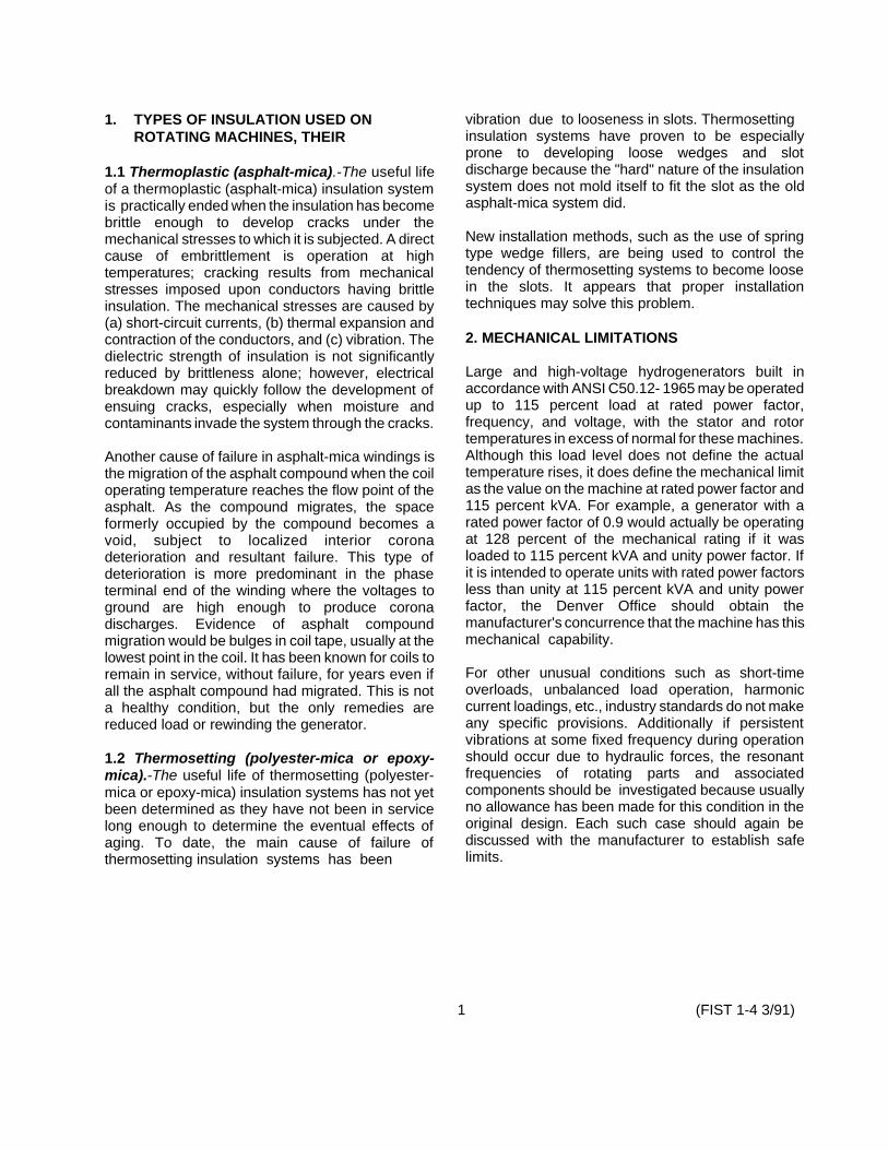
1. TYPES OF INSULATION USED ON ROTATING MACHINES, THEIR
1.1 Thermoplastic (asphalt-mica).-The useful life of a thermoplastic (asphalt-mica) insulation system is practically ended when the insulation has become brittle enough to develop cracks under the mechanical stresses to which it is subjected. A direct cause of embrittlement is operation at high temperatures; cracking results from mechanical stresses imposed upon conductors having brittle insulation. The mechanical stresses are caused by (a) short-circuit currents, (b) thermal expansion andcontraction of the conductors, and (c) vibration. The dielectric strength of insulation is not significantly reduced by brittleness alone; however, electrical breakdown may quickly follow the development of ensuing cracks, especially when moisture and contaminants invade the system through the cracks.
Another cause of failure in asphalt-mica windings is the migration of the asphalt compound when the coil operating temperature reaches the flow point of the asphalt. As the compound migrates, the space formerly occupied by the compound becomes a void, subject to localized interior corona deterioration and resultant failure. This type of deterioration is more predominant in the phase terminal end of the winding where the voltages to ground are high enough to produce corona discharges. Evidence of asphalt compound migration would be bulges in coil tape, usually at the lowest point in the coil. It has been known for coils to remain in service, without failure, for years even if all the asphalt compound had migrated. This is not a healthy condition, but the only remedies are reduced load or rewinding the generator.
1.2 Thermosetting (polyester-mica or epoxy-mica).-The useful life of thermosetting (polyestermica or epoxy-mica) insulation systems has not yet been determined as they have not been in service long enough to determine the eventual effects of aging. To date, the main cause of failure of thermosetting insulation systems has been
vibration due to looseness in slots. Thermosetting insulation systems have proven to be especially prone to developing loose wedges and slot discharge because the "hard" nature of the insulation system does not mold itself to fit the slot as the old asphalt-mica system did.
New installation methods, such as the use of spring type wedge fillers, are being used to control the tendency of thermosetting systems to become loose in the slots. It appears that proper installation techniques may solve this problem.
2. MECHANICAL LIMITATIONS
Large and high-voltage hydrogenerators built in accordance with ANSI C50.12- 1965 may be operated up to 115 percent load at rated power factor, frequency, and voltage, with the stator and rotor temperatures in excess of normal for these machines. Although this load level does not define the actual temperature rises, it does define the mechanical limit as the value on the machine at rated power factor and 115 percent kVA. For example, a generator with a rated power factor of 0.9 would actually be operating at 128 percent of the mechanical rating if it was loaded to 115 percent kVA and unity power factor. If it is intended to operate units with rated power factors less than unity at 115 percent kVA and unity power factor, the Denver Office should obtain the manufacturer's concurrence that the machine has this mechanical capability.
For other unusual conditions such as short-time overloads, unbalanced load operation, harmonic current loadings, etc., industry standards do not make any specific provisions. Additionally if persistent vibrations at some fixed frequency during operation should occur due to hydraulic forces, the resonant frequencies of rotating parts and associated components should be investigated because usually no allowance has been made for this condition in the original design. Each such case should again be discussed with the manufacturer to establish safe limits.
1 (FIST 1-4 3/91)

3. DAMAGE CAUSED BY EXPANSION OF COPPER
Temperature rise places stricter limits on loads than consideration of total temperature alone, Copper windings have a greater coefficient of expansion than stator steel, and in addition, are usually at a higher temperature. Under widely fluctuating temperatures, portions of the coils move in the steel slots with which they are in contact and abrasion and cracking of insulation may result. This movement is greater for machines with long slots than short slots, and increases with temperature rise. Since temperature rise varies approximately as the square of the load, it can be seen that a machine which must be overloaded should have its load maintained as constant as possible. This may be accomplished by holding constant load on the overloaded machine as much as possible, and carrying the fluctuating portion of the system load on other machines which are not overIoaded. The rate of load increase on cold machines should be limited to not more than 10 percent of rated load per minute except in emergencies when it is essential to pick up load promptly. This restriction does not apply to decreasing load, nor to varying load on a
warmed-up generator. Hydroelectric generators used for peaking power generation are sometimes loaded at the gate opening speed when peaking power is required on short notice. An example of the damage (tape separation) done to asphalt-mica insulated coils by excessive coil expansion and contraction is shown in figure 1.
4. LIMITING TEMPERATURES FORINSULATION
The safe operating temperature of rotating machine windings is limited by the heat which insulating material will stand without abnormal deterioration. This varies with different classes of insulating materials as shown in table 1. The hottest spot temperatures shown in the table have very little, if any, margin of safety for continuous operation. The IEEE Standard No. 492 indicates that life of class B insulation is halved with each 10 °C that the hottest spot temperature is above the limiting temperatures given in table 1 and a number of manufacturers believe that 8°C is a more realistic value. A curve ofinsulation life is shown in figure 2 for class B insulation. This curve is based on an assumed life of 30 years when operating continuously at the temperature shown.
Figure 1. - Example of stator end turn insulation cracking due to coil expansion and contraction. Photo 3-5828
(FIST 1-4 3/91) 2

Insulation life is affected by many other factors, such as cyclical loading duty, cleanliness, and rate of loading. so general conclusions on effect of temperature on insulation life are difficult to make.
5. HOTTEST SPOT ALLOWANCE
Insulation deterioration at a given temperature is approximately proportional to the length of time that the temperature is above the limiting value. Hottest spot temperatures shown in table 1 are not directly measurable values in actual machines and are, therefore, not used in machine ratings. Usual methods for measuring winding temperatures are embedded RTD's (resistance temperature detectors) or by measuring the winding resistance. The latter method is dated and is not used with newer machines; new machines have RTD's to measure winding temperatures and RTD's are being phased in to replace old temperature measuring methods as older machines are rewound or uprated. The measurable or “observable" temperature indicated by these devices will be less than the hottest spot temperature by an amount known as "temperature gradient" or "hottest spot allowance.' The actual hottest spot allowance varies with machine design, and, therefore, the limiting temperature rise is not the same for all machines. Values of limiting observable temperature are shown in table 1. It should be noted that data in table 1 apply only to insulating materials themselves and not to equipment in which they are used. To provide a reasonable service life for insulation in equipment, rated temperature rise should be used as the machine base allowable temperature.
6. LIMITING TEMPERATURE RISE
Observable temperature rise of each of the various parts of a rotating machine above the temperature of the cooling air should not exceed values given in table 2 when the machine is operated at rated power factor, voltage, and kVA (hereafter called rated
3
load). For open machines and for parts of enclosed machines which are cooled by open ventilation, such as collector rings, cooling air temperature is the average temperature of the external air at entrances to the ventilation opening of the machine. For totally enclosed machines, cooling air temperature is the average temperature of air leaving the coolers. In no event should cooling air temperature exceed 40 °C. Machines whose observable temperature rise at rated load exceeds values given in table 2 should be considered to have a reduced operational capacity to correspond to a loading value which does not exceed temperature rise values given in the table.
7. OPERATION OF MACHINES UNDERWARRANTY
New, newly uprated, or newly rewound machines operating under the manufacturer's warranty should not be loaded above design values. If the results of acceptance tests or the observation of station instruments should show that a machine will exceed temperature rise limitations of specifications, the machine should not be operated above these limitations until the contractor has had the opportunity to make the necessary corrections to the equipment. This is necessary to avoid nullifying contractual warranties on equipment as well as to permit a period of close observation of performance of new equipment to evaluate the desirability of allowing increased loading. After acceptance of the machine and analysis of heat runs, the Denver Office will prepare and issue capability curves for subsequent operational use (par.20).
8. OPERATION UP TO RATED CAPACITY
Hydroelectric generators fail into the following of the five categories:
a. Old machines that have not been rewound or uprated.
b. Old machines that have been rewound.
(FIST 1-4 3/91)

Table 1. - Limiting temperatures for insulating materials. (Note that these data apply to INSULATING MATERIALS and not to apparatus in which they are used.)
Limiting insulation Insulation class and description of material temperature o Celsius
By RTD or Hottest resistance spot
Class O - Consisting of cotton, silk, paper, and similar materials when 85 90 neither impregnated nor immersed in an insulating liquid dielectric Class A- Consisting of (1) cotton, silk, paper, and similar organic 100 105 materials when either impregnated or immersed in a liquid dielectric; (2) molded and laminated materials with cellulose filler, phenolic resins, and other resins of similar properties; (3) films and sheets of cellulose acetate and other cellulose derivatives of similar properties; and 4 varnishes (enamel as applied to conductors Class B - Consisting of mica, asbestos, fiberglass, dacron glass, and 120 130 similar inorganic materials in built-up form with organic or inorganic binding substances. A small proportion of class A materials may be used for structural purposes only. Fiberglass or asbestos magnet wire insulations are included in this temperature class. These may include supplemental organic materials such as polyvinyl acetyl or polyamide films. Class F - Consisting of mica, asbestos, fiberglass, dacron glass, and 140 155 similar inorganic materials, or combinations of these materials, suitably bonded with organic (varnishes or resins) or synthetic inorganic thermosetting resins of two types: epoxy mica and polyester mica. A very small proportion of cotton, silk, paper, and similar organic materials may be used for structural purposes only. Class H - Consisting of (1) mica, asbestos, fiberglass, and similar 160 180 inorganic materials in built-up form with binding substances composed of silicone compounds, or materials with equivalent properties; 2 silicone compounds in rubbery or resinous forms, or materials with equivalent properties. A minute proportion of class A materials may be used only where essential for structural purposes during manufacture. Class C - Consisting entirely of mica, porcelain, glass quartz, and similar Not inorganic materials, determined
c. Old machines that have been uprated,
d. New machines (post-1982).
e. Machines under warranty (new, recently rewound or uprated, etc.),
Unless special instructions for a particular machine state otherwise, machines in categories a. and b. above having class B or F insulationmay be operated to 115 percent of the original
rated load of the machine (or 115 percent of reduced operational capacity as discussed in paragraph 9) even though observable temperature rise values in table 2 are exceeded. In no event shall loading exceed 115 percent of rated load except in unusual cases as discussed in paragraph 9, or unless the Denver Office has approved higher loads.
Machines in categories c., d., and e. on page 4 should not be operated above rated capacity
4 (FIST 1-4 3/91)

except as described in paragraph 9, as upratedand new machines may not have overload capabilities.
The loading limitations given above are primarily set to guarantee a mechanical safety factor adequately below the endurance limit for the
machines and, therefore, the loading limit of a unit should not be raised on the basis of thermal and electrical capabilities alone.
Specific recommendations on a machines loading capabilities can be requested from the Code D8440, Denver Office.
Figure 2. - Life of generator insulation.
5 (FIST 1-1 3/91)

Table 2A. - Limiting observable temperature rise of indirectly cooled and directly water-cooled salient pole synchronous generators and synchronous generator/motors for hydraulic turbine applications - indirectly cooled machines manufactured before 1982
Method of Temperature rise(°C) Item Machine part Temperature Class B Class F
determination
(1) Armature windings of machines 1500 kV� A RTD 60 80 and above.
(2) Field windings of machines 1500 kV� A and Resistance. 80 100 above.
(3) Collector rings Thermometer. 65 85
(4) Cores and mechanical parts in contact with Thermometer. 55 75 or adjacent to insulation (except (except
motors) motors) 70 90
(motors) (motors)
(5) Miscellaneous parts such as brushholders, May attain such temperature as will not brushes, etc. injure the machine in any respect.
Table 2B. - Limiting observable temperature rise of indirectly cooled and directly water-cooled salient pole synchronous generators and synchronous generator/motors for hydraulic turbine applications - indirectly cooled machines manufactured after 1982
Method of Temperature rise (°C) Item Machine part Temperature Class B Class F
determination (1) Armature winding1+
(a) 7000 V and less Embedded detector.* 80 100 (b) over 7000 V to 15 000 V Embedded detector.* 75 90
inclusive. (c) over 15 000 V Embedded detector.* 70 85
(2) Field winding. Resistance. 80 100 (3) Collector rings. Thermometer. 85 85 (4) Cores and mechanical parts in contact Thermometer Not to exceed the value
with or adjacent to insulation or detector, for the associated adjacent insulation.**
(5) Miscellaneous parts (such as amortisseur windings, brush holders, brushes, etc.) may attain such temperatures as will not injure the machine in any respect.
* Embedded detectors are located within the slot of the machine and can be either resistance elements or thermocouples.
+ The temperature rise limits listed are for insulation system with thermosetting materials. For thermoplastic materials, the temperature rise limit shell be 70 °C.
** When core temperatures are measured at the outside diameter of the core, the limiting temperature rise shall be 5 °C less than the associated armature winding insulation limiting temperature rise.
(FIST 1-4 3/91) 6
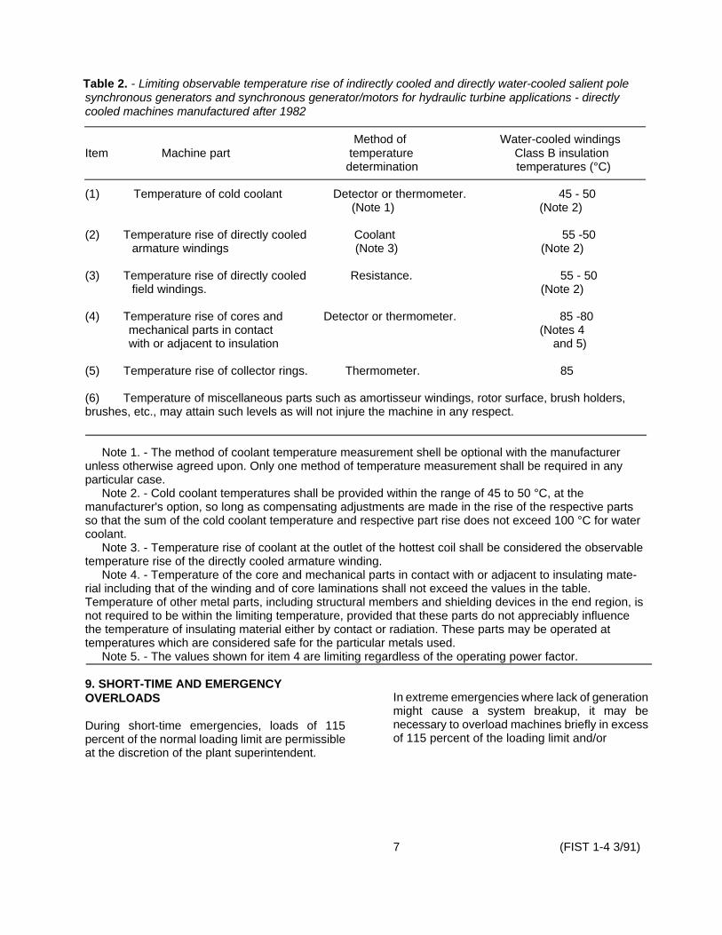
Table 2. - Limiting observable temperature rise of indirectly cooled and directly water-cooled salient pole synchronous generators and synchronous generator/motors for hydraulic turbine applications - directly cooled machines manufactured after 1982
Method of Water-cooled windings Item Machine part temperature Class B insulation
determination temperatures (°C)
(1) Temperature of cold coolant Detector or thermometer. 45 - 50 (Note 1) (Note 2)
(2) Temperature rise of directly cooled Coolant 55 -50 armature windings (Note 3) (Note 2)
(3) Temperature rise of directly cooled Resistance. 55 - 50 field windings. (Note 2)
(4) Temperature rise of cores and Detector or thermometer. 85 -80 mechanical parts in contact (Notes 4 with or adjacent to insulation and 5)
(5) Temperature rise of collector rings. Thermometer. 85
(6) Temperature of miscellaneous parts such as amortisseur windings, rotor surface, brush holders, brushes, etc., may attain such levels as will not injure the machine in any respect.
Note 1. - The method of coolant temperature measurement shell be optional with the manufacturer unless otherwise agreed upon. Only one method of temperature measurement shall be required in any particular case.
Note 2. - Cold coolant temperatures shall be provided within the range of 45 to 50 °C, at the manufacturer's option, so long as compensating adjustments are made in the rise of the respective parts so that the sum of the cold coolant temperature and respective part rise does not exceed 100 °C for water coolant.
Note 3. - Temperature rise of coolant at the outlet of the hottest coil shall be considered the observable temperature rise of the directly cooled armature winding.
Note 4. - Temperature of the core and mechanical parts in contact with or adjacent to insulating material including that of the winding and of core laminations shall not exceed the values in the table. Temperature of other metal parts, including structural members and shielding devices in the end region, is not required to be within the limiting temperature, provided that these parts do not appreciably influence the temperature of insulating material either by contact or radiation. These parts may be operated at temperatures which are considered safe for the particular metals used.
Note 5. - The values shown for item 4 are limiting regardless of the operating power factor.
9. SHORT-TIME AND EMERGENCYOVERLOADS In extreme emergencies where lack of generation
might cause a system breakup, it may be During short-time emergencies, loads of 115 necessary to overload machines briefly in excess percent of the normal loading limit are permissible of 115 percent of the loading limit and/or at the discretion of the plant superintendent.
7 (FIST 1-4 3/91)

maximum temperature permitted in table 2, but if and when this is done, a sacrifice in insulation life must be expected and the risk of mechanical damage to the machine must be considered. If it is anticipated that the emergency overload must be continued for 1 or more days, temporary supplemental cooling, as discussed in paragraph 13 should be installed.
10. LOAD LIMITATIONS OF ASSOCIATED EQUIPMENT
It is important that overloads should not be carried on rotating machines without an investigation of the limitations of associated equipment. Equipment such as cables, buses, reactors, circuit breakers, disconnecting switches, current transformers, and power transformers should be checked. Any one of these may constitute the practical limit in load carrying ability of the unit. On the machine itself, auxiliary equipment such as exciters or rheostats should be checked. The exciter should have sufficient margin while carrying the overload to take care of small fluctuations in load and voltage that may occur with minor system disturbances. In some cases it may be possible to ease the burden on the exciters of the machine being overloaded by transferring reactive kVA to other units of the same system.
11. COOLING WATER
If the mechanical limits of a machine are not exceeded, overload capacity of air-cooled machines with water cooled air coolers can be increased in some cases by increasing flow of cooling water so as to not exceed temperature limits in table 2. This is particularly true where cold cooling water is available. It should be emphasized that in addition to limiting the total temperature, temperature rise should be held within indicated limits. In a non-overload condition for class B insulation, if the limiting stator temperature rise is 60 °C, and the limiting total temperature is 100 °C, the difference between the temperature of the stator and the air leaving the cooler should not be more than 60 °C even though it may be possible to hold the total stator temperature to less than 100 °C by increasing flow or reducing the temperature of cooling water.
12. COOLING WATER REGULATION
As stated earlier, winding insulation life (a) is shortened by high temperature, and (b) is subject to mechanical damage by temperature cycling. Unfortunately, these facts place conflicting demands on any cooling system which is designed to lengthen the insulation service life, since, if maximum cooling of insulation, the possibility of mechanical damage due to temperature cycling under varying load is increased; likewise, if temperature cycling is to be minimized, the insulation temperature must be held constant at a relatively high value.
Therefore, there are presently in use two methods for controlling cooling water, each of which operates to lengthen insulation service life by controlling one (but not both) of the above conflicting requirements a. and b. as follows:
a. In cooling systems not provided with automatic regulation of water flow, the cooling water should be adjusted to produce minimum cooling air temperature without exceeding temperature rise limits in table 2 when the machine is carrying the maximum expected load. This flow should be constant for all other loads in order to maintain minimum insulation temperature at all times. However, winding temperatures should always be held above 10 °C.
Where cold cooling water is used, it is important to watch for condensation on piping and cooler surfaces within the generator and see that water is not being carried into the windings, causing rust or corrosion of metal parts. The amount of cooling water may have to be reduced to prevent condensation, or mixed with the warmer discharge water through a bypass connection to raise its temperature.
b. On some units, an automatic coolingwater flow control system has been installed to reduce the range of temperature
(FIST 1-4 3/91) 8
from no load to full load. On these units, the cooling water temperature is varied by mixing warm discharge water with fresh cool water as required to minimize temperature variations.
13. SUPPLEMENTAL COOLING
For air/water-cooled units, when not limited by the mechanical capability, the capacity may be increased by using colder water, or by increasing the quantity of water circulated through the coolers. Open-type units depend on the surrounding air for the removal of heat. By increasing circulation of the air, or by cooling the air in some manner, capacity of open-type machines can be increased, but temperature rise limitations of table 2 must be kept in mind. Ventilating fans may be used to direct air toward the machine. Advantage should be taken of windows and doors to admit outside air. In several instances, cooling has been improved by building a duct to bring outdoor air directly into the turbine pit and eliminating the possibility of warm air exhausted from the generator being recirculated into the machine, if artificial cooling of the air is attempted, care should be taken to prevent moisture or dusty air from being drawn into the generator.
14. KEEPING MACHINES CLEAN
Another factor which should be watched in machines, especially if they are to be overloaded, is accumulation of dust and dirt. Dust and dirt hinder heat dissipation and can adversely affect the voltage grading system; therefore, internal cleanliness of the machine is important to assure proper cooling and retention of the voltage grading should be cleaned regularly to assure maximum heat transfer. When generator temperatures appear to be getting higher, temperature data should be compared with log sheet data of past years, or cleaned to determine the amount of temperature when the machine was new, or just after being rise due system. Particular attention should be given to field winding because dirt is more apt to deposit on irregular surfaces. Inspection should be made of ventilating passages of the stator core for dirt accumulations. For machines having recirculating systems, the cooler should be cleaned regularly to assure maximum heat transfer. When generator temperatures appear to be getting higher, temperature data
should be compared with log sheet data of past years, or when the machine was new, or just after being cleaned to determine the amount of temperature rise due to accumulation of dirt and estimate the benefit obtainable by cleaning. Reduction of approximately 10 °C in the stator temperature of of an open-type Bureau generator resulted from a thorough cleaning and enable the plant to carry more load during a critical period. Where possible, suction should be used to clean machines, since with this method the grit and dust is not merely moved from one resting place to another. Clean, dry compressed air at a pressure of not over 276 kPa (40 lb/in2 ) may be used to blow dust out of the wound section or other places not accessible to the suction attachment. If dust is allowed to accumulate on the windings, it not only prevents proper dissipation of heat and circulation of cooling air through ducts, but also tends to hold moisture and oil against insulation. In the cleaning process, slip rings and commutators should be cleaned of dust to prevent abrasion. Oil should never be allowed anywhere on machines except where it is required for lubrication. Oil harms commutators by carbonizing mica insulating segments between bars. Oil on windings catches dirt and dust and the resulting gummy compound hastens ultimate failure of insulation. Flammable or highly toxic cleaning mixtures such as carbon tetrachloride should not be used. Several satisfactory commercial solvents are now available for this purpose. Windings should not be allowed to soak in any solvent, but just enough solvent should be used to loosen grease so that it can be wiped off. Ample ventilation should be supplied for workmen. Any oil leaks should, of course, be promptly repaired.
15. TEMPERATURE OF OLD MACHINES
For older machines, special care should be taken in determining the temperature of all parts if operation at overload is contemplated. Many older machines have stator core laminations of poor quality steel and inadequate ventilating systems for taking care of losses in the area close to the air gap. Increased load or operation above normal voltage means more leakage flux and even higher temperatures for these machines. During underexcited operation, some machines are subject to above normal temperatures on end and finger plates or laminations at each end of
9 (FIST 1-4 3/9)

the stator core because of excessive leakage flux near the winding end turn area. Most machines are not subject to this trouble, but the condition should not be overlooked in the few cases where it exists. Table 2 shows allowable temperature rises of various components of the machine.
16. CHANGING VOLTAGE TO REDUCE TEMPERATURE
Some reduction in operating temperature is sometimes possible, particularly on synchronous motors, without reducing load, by changing the operating voltage. Stator iron losses and temperatures increase with increased applied voltage, and vice versa. Copper losses and temperature are proportional to the square of the stator current. If stator laminations run cool and coils comparatively hot, an increase in stator voltage by changing transformer taps will decrease the copper temperature and increase the iron temperature, without a change in output. The minimum stator winding temperature for any kW load will be obtained at 100 percent power factor.
17. LOAD TEMPERATURE TESTS
For all types of machines, an indication of the amount of overload which can be carried can be determined from the mechanical limits and a series of temperature tests. A prediction can be made from results of a single temperature run by computing the temperature rise as outlined in paragraph 19. More accurate indications are obtained by making temperature rise test runs at 50, 75, and 100 percent load. However, the best plan is to make a temperature test at the actual overload which the machine is desired to carry. Voltage and power factor should be held constant for all runs so that the internal voltage and core loss will be about the same. Switchboard instruments should be supplemented with accurately calibrated instruments during overloading of the machine. Each load temperature test should be run with constant load, excitation, cooling water, etc., until the temperature
rise above ambient air temperature reaches a constant value, and readings should be taken at 30-minute intervals for several hours alter conditions become stabilized. Specific test procedures may be obtained from the Denver Office. A curve of generator amperes versus stator temperature rise plotted from the test data may be of value for future reference.
18. MEASURING STATOR TEMPERATURE
Temperature of the stator coils should be taken as the highest reading obtained. Where embedded RTDs are provided for measuring the stator temperature and a temperature check should be made by placing a few thermocouples on the stator iron (core). Where no embedded RTDs are installed, it is desirable to use a number of thermocouples for measuring stator temperature; thermocouples should be placed on the hottest parts of the stator steel, well protected from the airstream, and the highest thermocouple readings should be used. Thermocouples may be held against the surface with duct seal. Precautions should be taken if thermocouples are used to measure end turn temperatures, end turn coils could be charged to nearly the turn-to-ground voltage during machine operation. Specific test procedures may be obtained from the Denver Office.
19. MEASURING FIELD TEMPERATURE
Field temperature for both static or rotating excitation systems shall be determined by the resistance method from field voltage and current readings while the machine is carrying the load for which data are desired. Specific test procedures may be obtained from the Denver Office. An accurate voltmeter and ammeter should be used. Field voltage should be measured at collector rings by pilot brushes. If no pilot brushes are provided, one of the main brushes on each ring can be disconnected and insulated from the brush holder by a layer of paper and used as
(FIST 1-4 3/91) 10

temporary pilot brushes. Field winding temperature can be found from the following formula:
R2T2 = (234.5 + T1) - 234.5
R1
where:
T2 = temperature (OC) corresponding to final resistance
T1 = temperature (OC) corresponding to Initial resistance R1
R2 = field volts field amperes
Field resistance R1 at temperature T1 is usually given on the generator manufacturer's test report. If these data are not available, resistance should be measured after the machine has been shut down for at least 12 hours with constant ambient temperature and using ambient temperature for T1.
Data obtained from field temperature tests can be used for making up curves as shown in figure 3b for future use in determining field temperature from readings of field volts and amperes. These curves will be particularly valuable if the field temperature is the limiting factor in overloading the generator. While making the field temperature test, readings of the accurate voltmeter and ammeter used should be compared with the switchboard voltmeter and ammeter and the latter should be corrected if necessary. It is important that the field voltages be measured at collector rings. If pilot brushes are not provided, an allowance for brush drop can be made as found from comparison of voltage measured on the main brushes and temporary pilot brushes, The temperature-resistance curve, figure 3a, is a straight line and can be plotted through any two points of resistance and corresponding temperature, such as R1, T1, and R2, T2 used in the above formula. Curves in figure 3b should be plotted in the range of about 80 to 130 percent of full load field amperes and corresponding voltage, so as to obtain a broad spread in the temperature scale. Field temperature readings are not
considered important unless they are near the limiting temperature. Each curve in figure 3b is a straight line plotted between two values of voltage and its corresponding current giving the same value of resistance. That is,
E1 E2R = =
I1 I2
The value of R is first found from figure 3a for each value of temperature for which a curve is to be made.
20. COMPUTING STATOR WINDINGTEMPERATURE RISE
At times it is difficult or inconvenient to measure stator winding temperature rise by tests at all desired loadings; therefore, a method of computing temperature rise, TR1 from available temperature test data is outlined below:
The basic equation to be used is:
TR = C1 C2 (kVA)2
This equation has two unknowns, C1 and C2, and test data are required from two heat runs to find these unknown values. By substituting TR1 and kVA1 in equation for heat run No. TR2 and kVA2 for heat run No. 2 and subtracting one equation from the other, C2 can be found. Substituting C2 back into either equation gives a value for C1. The constant C1 represents stator winding temperature rise for no-load losses. If it is more convenient, or if data are already available, stator winding temperature rise attained during a no-load, rated voltage heat run may be used for C1.
After C1 and C2 are known, the stator winding temperature rise, TR, for other desired loading conditions may be calculated.
21. GENERATOR CAPABILITY CURVES
Capability curves for large rotating machines are required to establish safe operational limits. These curves are required for inclusion involved.
11 (FIST 1-4 3/91)

Figure 3. - Typical field resistance temperature curves.
21.1. Overexcited (boosting voltage).-A capability curve is defined as a curve which shows boundaries of the area on the kilowatt-kilo-var diagram within which a machine may be operated continuously. Capability curves are furnished for each installation which show kVA capability throughout the expected range of operation and which include the range of permissible operating voltages. One such curve sheet for a generator rated 65 789 kVA, 13 800 volts, and 95 percent power factor is shown in figure 4. The highest operating voltage is limited to 105 percent of rated terminal voltage in order to meet voltage limitation requirements of the Standards for Synchronous Generators. Capability curves for machines in categories a and b in paragraph 7 not operating under manufacturer's warranty will normally show limitations for 115 percent of nameplate ratings. Limitations for new machines (post 1982) will normally be the nameplate rating,
For uprated generators, the kilowatt rating rather than the kVA rating is set at a maximum fixed value which should not be exceeded. The Capability curve will be based on a constant kilowatt load.
21.2. Underexcited (bucking voltage).-Generator capability when operating underexcited is limited by the permissible armature current and steady-state stability limit of the machine. A capability curve sheet for underexcited operation is shown in figure 5. Steady-state stability limit is a function of system at this point are above terminal voltage. As the kilovar load is increased at zero-kilowatt load, the generator will eventually become unstable and start to slip poles. The kVA
reactance, and generator and armature current rated values so that continuous operation near this point is out of the generator reactances, external question because of armature heating.
Most modern generators may be operated continuously at zero field current and rated voltage except for a few machines with special electrical characteristics such that stator heating becomes a problem. Modern, continuously acting voltage regulators are equipped with underexcited reactive ampere limiters which permit machine operation at underexcited capability determined by thermal limitations without danger of the machine becoming unstable. These limiters respond to underexcited reactive stator current and to terminal voltage. As a part of the regulating function, limiters automatically hold the underexcited reactive amperes at lower values as kilowatt load on the machine is increased. Limiter settings are adjustable so that their operating characteristics may be coordinated with the thermal capability curve and the steady state stability curve. The Denver Office, should be consulted when any operating problems arise concerning underexcited operating capability either under load or strictly as a synchronous condenser. Additional underexcited synchronous condenser capacity is sometimes made available by operating with negative field current under automatic control of voltage regulators. However, any changes in limiter settings to accommodate this operation must be coordinated with machine thermal limitations and with the settings of the loss of excitation relays.
13 (FIST 1-4 3/91)

(FIST 1-1 3/91) 14

(FIST 1-4 3/91)15

22. REFERENCES
General Principles upon which Temperature Limits are Based in the Rating of Electrical Machines and Other Equipment, IEEE Stan-dard No. 1, 1969
Guide for Functional Evaluation of Insulation Systems for Large High Voltage Machines
IEEE Standard No. 434-1973
Test Procedures for Synchronous Machines, IEEE publication No. 115, 1965
General Principles of Temperature measurements as Applied to Electrical Apparatus
IEEE Publication No. 119, 1974
American Standard for Rotating Electrical Machinery, American National Standard C50.10,
1977; C50.11, 1965; C50.12, 1982; C50.13, 1977
Guide for Operation and Maintenance of Hydrogenerators, IEEE Standard No. 492
1974.
(FIST 1-4 3/91) 16


