PERMASCOPE ISOSCOPE MP0R DUALSCOPE MP0R · MP0R Instrument Series 5 2 Instrument descriptionThe...
68
Operator‘s Manual PERMASCOPE ® MP0R ISOSCOPE ® MP0R DUALSCOPE ® MP0R PERMASCOPE ® MP0R-FP DUALSCOPE ® MP0R-FP DUALSCOPE ® MP0R-FPW DUALSCOPE ® MP0RH-FP Coating Thickness Material Analysis Microhardness Material Testing
Transcript of PERMASCOPE ISOSCOPE MP0R DUALSCOPE MP0R · MP0R Instrument Series 5 2 Instrument descriptionThe...

Operator‘s Manual
C
PERMASCOPE® MP0RISOSCOPE® MP0RDUALSCOPE® MP0R
PERMASCOPE® MP0R-FP DUALSCOPE® MP0R-FP DUALSCOPE® MP0R-FPW DUALSCOPE® MP0RH-FP
oating Thickness Material Analysis Microhardness Material Testing
Instrument series MP0RInstruments for coating thickness measurements.
On our home page www.helmut-fischer.com you will find the addresses of our sole agencies and subsidiary companies around the globe.
© 2015 by Helmut Fischer GmbH Institut für Elektronik und Messtechnik, Ger-many.This operator’s manual remains the copyrighted property of Helmut Fischer GmbH. All rights reserved. This manual may not be reproduced by any means (print, photocopy, microfilm or any other method) in full or in part, or pro-cessed, multiplied or distributed to third parties by electronic means without the written consent of Helmut Fischer GmbH.Subject to correction and technical changes.PERMASCOPE®, ISOSCOPE® and DUALSCOPE® are registered trade marks of the Helmut Fischer GmbH Institut für Elektronik und Messtechnik in Germany and/or other countries.Microsoft® and Excel® is a registered trademark of the Microsoft Corporation in the USA and other countries.Note: The fact, that the trademark characters ® and ™ may be missing does not indicate that such names are free trademarks.
Document number 902-517
Issue date 12-2015 (valid from software version PGA09)
ManufacturerHelmut Fischer GmbH Phone: +49 (0) 70 31 3 03 - 0Institut für Elektronik und Messtechnik Fax: +49 (0) 70 31 3 03 - 710Industriestraße 21 www.helmut-fischer.comD-71069 Sindelfingen [email protected]
Quality Assurance System of the Helmut Fischer GmbH
DIN EN ISO/IEC 17025
Calibration lab accredited for certified mass per unit area standards
DIN EN ISO 9001:2008
Management system certified by DNV GL - Business Assur-ance

1 Safety information . . . . . . . . . . . . . . . . . . . . . . . . . . . . . . . . . . 11.1 Read the operator‘s manual carefully before operating . . . . . . . 11.2 Warnings used . . . . . . . . . . . . . . . . . . . . . . . . . . . . . . . . . . 11.3 Symbols used . . . . . . . . . . . . . . . . . . . . . . . . . . . . . . . . . . 11.4 Intended use . . . . . . . . . . . . . . . . . . . . . . . . . . . . . . . . . . . . 21.5 Safety of the electrical equipment . . . . . . . . . . . . . . . . . . . . . . 21.6 Servicing and repairs . . . . . . . . . . . . . . . . . . . . . . . . . . . . . . 21.7 Ambient conditions . . . . . . . . . . . . . . . . . . . . . . . . . . . . . . . . 31.8 Disposal . . . . . . . . . . . . . . . . . . . . . . . . . . . . . . . . . . . . . . . 4
2 Instrument description . . . . . . . . . . . . . . . . . . . . . . . . . . . . . . . 52.1 Areas of application . . . . . . . . . . . . . . . . . . . . . . . . . . . . . . . 52.2 Instrument parts . . . . . . . . . . . . . . . . . . . . . . . . . . . . . . . 62.3 Display . . . . . . . . . . . . . . . . . . . . . . . . . . . . . . . . . . . . . . 72.4 Information and symbols on the display. . . . . . . . . . . . . . . . . . 82.5 Signals after measurement acquisition. . . . . . . . . . . . . . . . . . . 92.6 Multifunctional keys . . . . . . . . . . . . . . . . . . . . . . . . . . . . . . 102.7 Instrument operation - Make settings . . . . . . . . . . . . . . . . . . . 102.8 Main menus - function overview . . . . . . . . . . . . . . . . . . . . . . 12
3 Switching the instrument on and off . . . . . . . . . . . . . . . . . . . . 14
4 Measurement . . . . . . . . . . . . . . . . . . . . . . . . . . . . . . . . . . . . . 15
5 Settings for measurement . . . . . . . . . . . . . . . . . . . . . . . . . . . . 185.1 Functions you must set before starting measurement . . . . . . . . 185.2 Further settings for measurement. . . . . . . . . . . . . . . . . . . . . . 23
6 Taking influencing variables into account . . . . . . . . . . . . . . . . 256.1 Types of calibrations. . . . . . . . . . . . . . . . . . . . . . . . . . . . . . 256.2 Calibration - essential information. . . . . . . . . . . . . . . . . . . . . 276.3 Normalisation . . . . . . . . . . . . . . . . . . . . . . . . . . . . . . . . . . 286.4 Calibration . . . . . . . . . . . . . . . . . . . . . . . . . . . . . . . . . . . . 306.5 Simple Calibration . . . . . . . . . . . . . . . . . . . . . . . . . . . . . . . 336.6 User master calibration . . . . . . . . . . . . . . . . . . . . . . . . . . . 35
MP0R Instrument Series i

6.7 Lock the calibration functions . . . . . . . . . . . . . . . . . . . . . . . . 376.8 Unlock the calibration functions. . . . . . . . . . . . . . . . . . . . . . . 37
7 Evaluation . . . . . . . . . . . . . . . . . . . . . . . . . . . . . . . . . . . . . . . . 387.1 Res > Result - Description of the statistical characteristics . . . . . 38
8 Deleting. . . . . . . . . . . . . . . . . . . . . . . . . . . . . . . . . . . . . . . . . . 398.1 Deleting measurement readings. . . . . . . . . . . . . . . . . . . . . . . 398.2 Deleting the calibration . . . . . . . . . . . . . . . . . . . . . . . . . . . . 398.3 Deleting the (user) master calibration . . . . . . . . . . . . . . . . . . 398.4 Resetting the instrument to the factory settings . . . . . . . . . . . . . 40
9 Data transfer . . . . . . . . . . . . . . . . . . . . . . . . . . . . . . . . . . . . . . 419.1 Preparation for the data transfer . . . . . . . . . . . . . . . . . . . . . . 419.2 Transferring measurement readings to the PC . . . . . . . . . . . . . 41
10 Display and measurement value display . . . . . . . . . . . . . . . . . 45
11 Malfunctions - What should you do? . . . . . . . . . . . . . . . . . . . . 47
12 Technical data . . . . . . . . . . . . . . . . . . . . . . . . . . . . . . . . . . . . . 52
13 Ordering information . . . . . . . . . . . . . . . . . . . . . . . . . . . . . . . 58
Index. . . . . . . . . . . . . . . . . . . . . . . . . . . . . . . . . . . . . . . . . . . . . I
ii MP0R Instrument Series

Safe
ty in
form
atio
n
1 Safety informationIf you use the instrument as intended and observe the safety information, the instrument poses no danger. Read and follow these instructions and observe the safety information. Also ob-serve generally applicable safety and accident prevention regulations.1.1 Read the operator‘s manual carefully before operating
• Make sure to read this operator’s manual carefully before taking the in-strument into operation.
• Keep the manual in a safe place, so that you will be able to consult it whenever necessary.
1.2 Warnings used
1.3 Symbols used
ATTENTION Indicates a danger that can lead to damage or destruction of the product.
CAUTION Indicates a danger that can lead to minor or moder-ately severe injuries.
WARNING Indicates a danger that can lead to fatal or severe injuries.
DANGER Indicates a danger that can lead immediately to fatal or severe injuries.
NoteIndicates important information and notes.
MP0R Instrument Series 1

Safe
ty in
form
atio
n
1.4 Intended useThe MP0R instrument series are to be used solely to measure the coating thick-ness.Only accessories approved or recommended by the manufacturer may be con-nected to the instrument.Any use beyond this is not the intended use. The risk of damage ensuing there-from is borne solely by the user.
1.5 Safety of the electrical equipment
EMC
The instrument complies with the law on the electromagnetic compatibility of apparatus (2014/30/EC). The measured values are not influenced by the maximum values of the types of interference listed in standard EN 61000-6-2 (which refers to standards EN 61000-4-2, EN 61000-4-3 and EN 61000-4-4).
Low voltage
The instrument complies with the Low-Voltage Directive 2014/35/EC.
Probe connection cable (Only instrument models MP0R-FP)
1.6 Servicing and repairsModifications, repairs as well as maintenance and service work on the instru-ment and accessories may be carried out only by service personnel authorised by the manufacturer.Exception: Changing the batteries.
ATTENTION Wire breakageBending the probes and other connection cables sharply can cause broken wires. It is then no longer possible to measure.► Roll the probe connection cable into a
radius of at least 20 mm (0.79 inch).► Do not kink or pinch connection cables.
R 20 mm
2 MP0R Instrument Series

Safe
ty in
form
atio
n
1.7 Ambient conditionsAmbient temperature during operation: 0 ... +40 °C / +32 ... +104 °FStorage and transport temperature: +5 ... +60 °C (+41 ... +140 °F)
ATTENTION Risk of damage to the instrument from excessively high tem-peraturesWhen exposed to sunshine, the areas behind glass windows (e.g. in an automobile) can easily reach temperatures in excess of +60 °C (+140 °F). This can damage the instrument.► Do not leave or store the instrument and accessories
behind glass windows or next to heat sources such as radiators etc.!
ATTENTION Risk of damage to the instrument from acidThe instrument and accessories are not acid-resistant.► Do not bring the instrument and accessories into contact
with acids or acid containing liquids!
ATTENTION Hazard of short-circuitThe hazard of a short circuit exists if the instrument and acces-sories come into direct contact with liquids! ► Operate, leave or store the instrument and accessories
only at locations with a relative humidity of 30 % to 90 % (non-condensing).
ATTENTION The instrument and accessories are not suitable for use in po-tentially explosive environments.► Do not operate the instrument and accessories in poten-
tially explosive areas!
MP0R Instrument Series 3

Safe
ty in
form
atio
n
1.8 DisposalDisposalDo not dispose of waste electrical equipment and electronic accessories with household refuse. ► Put damaged or used batteries, waste electrical and
electronic equipment in the appropriate collection bins! Please observe the regulations in your region for proper handling of waste electrical equipment and electronic accessories.
4 MP0R Instrument Series
Instr
umen
t des
crip
tion
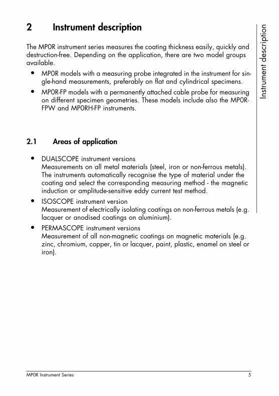
2 Instrument descriptionThe MP0R instrument series measures the coating thickness easily, quickly and destruction-free. Depending on the application, there are two model groups available. • MP0R models with a measuring probe integrated in the instrument for sin-
gle-hand measurements, preferably on flat and cylindrical specimens.• MP0R-FP models with a permanently attached cable probe for measuring
on different specimen geometries. These models include also the MP0R-FPW and MP0RH-FP instruments.
2.1 Areas of application
• DUALSCOPE instrument versionsMeasurements on all metal materials (steel, iron or non-ferrous metals). The instruments automatically recognise the type of material under the coating and select the corresponding measuring method - the magnetic induction or amplitude-sensitive eddy current test method.
• ISOSCOPE instrument versionMeasurement of electrically isolating coatings on non-ferrous metals (e.g. lacquer or anodised coatings on aluminium).
• PERMASCOPE instrument versionsMeasurement of all non-magnetic coatings on magnetic materials (e.g. zinc, chromium, copper, tin or lacquer, paint, plastic, enamel on steel or iron).
MP0R Instrument Series 5

Instr
umen
t des
crip
tion
2.2 Instrument partsNo. Description
1 Signal LED for displaying the measurement acquisition and limit val-ue violation
2 Carrying strap
3 Displays
4 Multifunctional keys
5 USB port
6 Mounting support
7 Impact protective cover
8 MP0R: ProbeMP0R-FP/MP0R-FPW/MP0RH-FP: Probe with cable permanently connected
9 Battery compartment cover
10 Protective probe cap (only for MP0R instrument models)
1
2
3
4
6
8 9
Front side of the instrument (shown on the DUAL-SCOPE MP0R with impact protective cover)
Rear side of instrument, with impact protective cover
10
5
7
6 MP0R Instrument Series
Instr
umen
t des
crip
tion
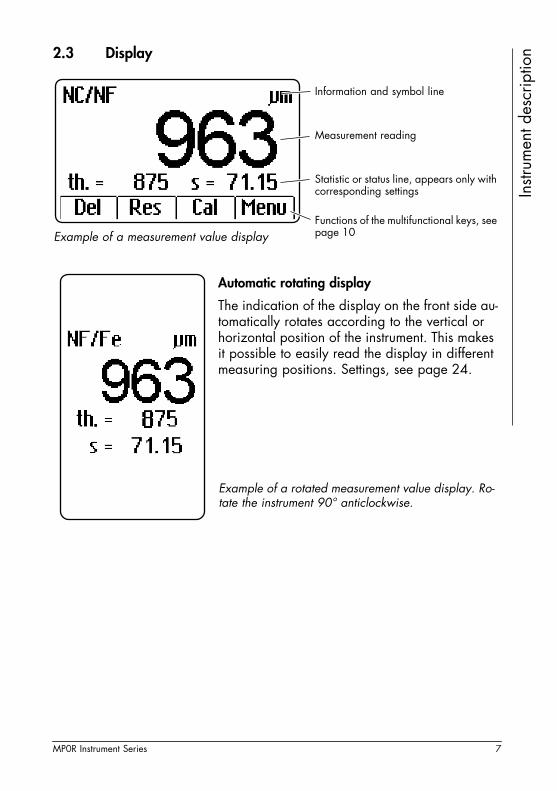
2.3 DisplayExample of a measurement value display
Information and symbol line
Measurement reading
Statistic or status line, appears only with corresponding settings
Functions of the multifunctional keys, see page 10
Example of a rotated measurement value display. Ro-tate the instrument 90° anticlockwise.
Automatic rotating display
The indication of the display on the front side au-tomatically rotates according to the vertical or horizontal position of the instrument. This makes it possible to easily read the display in different measuring positions. Settings, see page 24.
MP0R Instrument Series 7

Instr
umen
t des
crip
tion
2.4 Information and symbols on the displaySymbols Meaning
NF/Fe The magnetic induction test method is used for coating thickness measurement - non-ferromagnetic coating mater-ial (NF) on steel or iron (Fe).
NC/NF The amplitude-sensitive eddy current test method is used for coating thickness measurement - electrically non-con-ductive coating material (NC) on non-ferromagnetic, elec-trically conductive substrate material (NF).
Dual Dual mode is enabled. Measurement can be done with both test methods. (Only for DUALSCOPE instruments pos-sible, setting see page 23)
μm, mils Unit of the displayed measurement reading, setting see page 23
PA2 The measurement specification SSPC-PA2 is active, setting see page 18.
PSPC The measurement specification IMO 90/10 is active, set-ting see page 18.
Zero The function Normalization is active, see from page 25.
Cal The function Calibration is active, see from page 25.
Master The function Master Calibration is active, see page 26.
offs The function Offset is active, see page 21.
Battery voltage too low. Replace the batteries immediate-ly.
/
/
The measurement reading is above/below the preset limit value. Setting the limit values see page 19.
th. Mean value, enable/disable the mean value display see page 45.
s Standard deviation, enable/disable the standard devia-tion display see page 45
(Front)
(Top)
8 MP0R Instrument Series
Instr
umen
t des
crip
tion
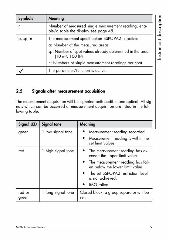
2.5 Signals after measurement acquisition
The measurement acquisition will be signaled both audible and optical. All sig-nals which can be occurred at measurement acquisition are listed in the fol-lowing table:
n Number of measured single measurement reading, ena-ble/disable the display see page 45.
a, sp, n The measurement specification SSPC-PA2 is active:a: Number of the measured areas sp: Number of spot values already determined in the area
(10 m²; 100 ft²)n: Numbers of single measurement readings per spot
The parameter/function is active.
Signal LED Signal tone Meaning
green 1 low signal tone • Measurement reading recorded• Measurement reading is within the
set limit values.
red 1 high signal tone • The measurement reading has ex-ceede the upper limit value.
• The measurement reading has fall-en below the lower limit value.
• The set SSPC-PA2 restriction level is not achieved.
• IMO failed
red or green
1 long signal tone Closed block, a group separator will be set.
Symbols Meaning
MP0R Instrument Series 9
Instr
umen
t des
crip
tion
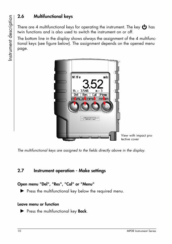
2.6 Multifunctional keysThere are 4 multifunctional keys for operating the instrument. The key has twin functions and is also used to switch the instrument on or off. The bottom line in the display shows always the assignment of the 4 multifunc-tional keys (see figure below). The assignment depends on the opened menu page.
The multifunctional keys are assigned to the fields directly above in the display.
2.7 Instrument operation - Make settings
Open menu "Del", "Res", "Cal" or "Menu"
► Press the multifunctional key below the required menu.
Leave menu or function
► Press the multifunctional key Back.
View with impact pro-tective cover
10 MP0R Instrument Series

Instr
umen
t des
crip
tion
Select function or parameter► Press the multifunctional keys to move the cursor. A check mark indicates that the function is active.
Enter value/number
Limit values: Measure with the instrument one reference value and use the multifunctional keys to tune the exact value. Numbers: Use the multifunctional keys to tune the desired value.
Example
Select the language.Menu > Settings > OK > Language > OK > select the language > OK
Step by step procedure
1. Press the following multifunctional keys in succession: Menu, till Settings, OK, till Language, OK.
2. Use the multifunctional keys to select the desired language.3. Press the multifunctional key OK to quit the function.
MP0R Instrument Series 11
Instr
umen
t des
crip
tion
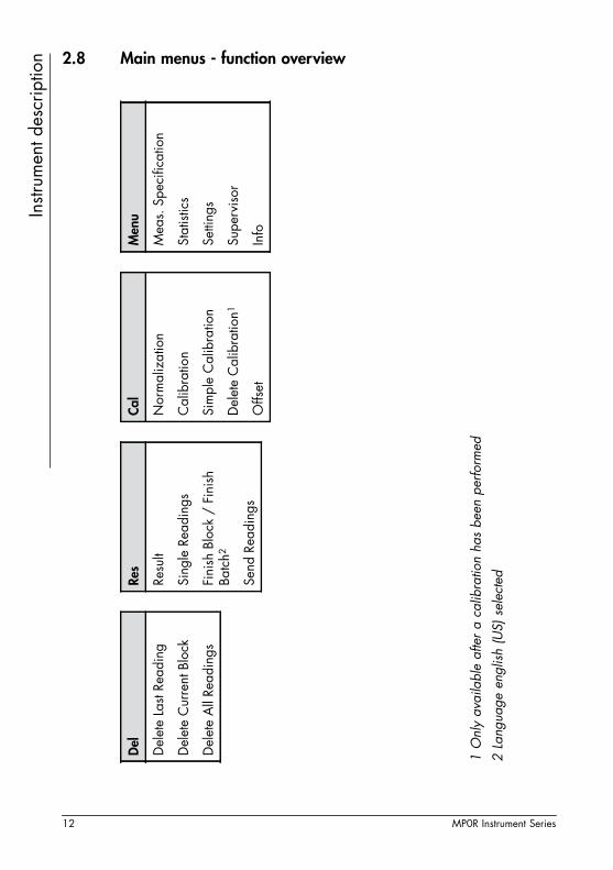
2.8 Main menus - function overview1 O
nly
avai
labl
e af
ter
a ca
libra
tion
has
been
per
form
ed
2 La
ngua
ge e
nglis
h (U
S) s
elec
ted
Del Del
ete
Last
Read
ing
Del
ete
Cur
rent
Blo
ck
Del
ete
All
Read
ings
Res
Resu
lt
Sing
le R
eadi
ngs
Fini
sh B
lock
/ F
inis
h Ba
tch2
Send
Rea
ding
s
Cal
Nor
mal
izat
ion
Cal
ibra
tion
Sim
ple
Cal
ibra
tion
Del
ete
Cal
ibra
tion1
Offs
et
Men
u
Mea
s. S
peci
ficat
ion
Stat
istic
s
Setti
ngs
Supe
rvis
or
Info
12 MP0R Instrument Series

Instr
umen
t des
crip
tion
Menu - function overview2 La
ngua
ge e
nglis
h (U
S) s
elec
ted
* O
nly
avai
labl
e fo
r th
e in
strum
ent v
ersi
ons
DU
ALS
CO
PE
Not
eTh
e fu
nctio
ns
are
avai
labl
e de
pend
s on
the
sele
cted
mea
s-ur
emen
t spe
cifi-
catio
n.
Men
u
Mea
s. S
peci
ficat
ion
Def
ault
SSPC
-PA
2
IMO
90/
10
Stat
istic
s
Dis
play
sta
tistic
s
Bloc
k Si
ze /
Bat
ch
Size
2
i Sin
gle
Read
ings
Setti
ngs
Stor
e re
adin
gs
Free
runn
ing
mod
e /
Scan
Mod
e2
Spec
ifica
tion
limits
/
HiLo
Ala
rm2
Rota
ting
disp
lay
Dua
l mod
e*
Aud
ible
sig
nal
Dec
imal
pla
ces
Out
put
Gro
up s
epar
ator
Cha
nge
unit
Back
light
Con
trast
Lang
uage
Switc
h of
f tim
e
Supe
rvis
or
Lock
Cal
ibra
tion
/ C
al L
ock2
Mas
ter
Cal
ibra
tion
Del
ete
Mas
ter
Cal
.1
Mea
sure
d va
riabl
e
Initi
aliz
atio
n
1 O
nly
avai
labl
e af
ter
a m
aste
r ca
libra
tion
has
been
per
form
ed
Info
MP0R Instrument Series 13

14 MP0R Instrument Series
Switc
hing
the
instr
umen
t on
and
off 3 Switching the instrument on and off
3.1 Switching the instrument on
► Press the key to switch on the instrument.
3.2 Switching the instrument off
► Press the key for 2 seconds to switch off the instrument. The indication on the display disappears.
3.2.1 Auto switch-off
After approx. one minute, the instrument automatically switches off if no action has taken place within this time period (such as the actuation of a key or a measurement acquisition). You can increase the time period for the auto switch-off to 5 minutes.
Open menu
► Select with the multifunctional keys Menu > Settings > OK > Switch off time
Change auto switch-off time
► Select the desired switch-off time (after about 1 min or 5 min) with the multifunctional key and confirm the selection with OK.
Note
Only for MP0R instrument models: Remove the orange-coloured protective probe cap before measuring.
Mea
sure
men
t
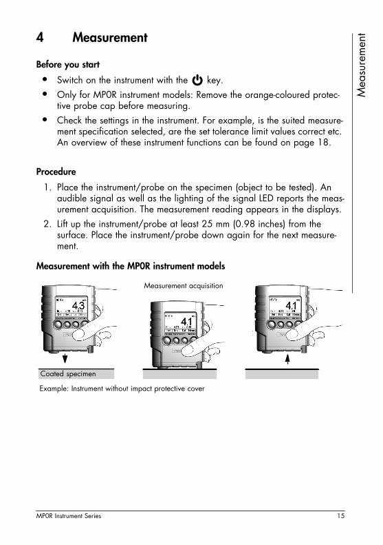
4 MeasurementBefore you start
• Switch on the instrument with the key.• Only for MP0R instrument models: Remove the orange-coloured protec-
tive probe cap before measuring.• Check the settings in the instrument. For example, is the suited measure-
ment specification selected, are the set tolerance limit values correct etc. An overview of these instrument functions can be found on page 18.
Procedure
1. Place the instrument/probe on the specimen (object to be tested). An audible signal as well as the lighting of the signal LED reports the meas-urement acquisition. The measurement reading appears in the displays.
2. Lift up the instrument/probe at least 25 mm (0.98 inches) from the surface. Place the instrument/probe down again for the next measure-ment.
Measurement with the MP0R instrument models
Coated specimen
Measurement acquisition
Example: Instrument without impact protective cover
MP0R Instrument Series 15

Mea
sure
men
t
Handling the probe of the MP0R-FP and MP0RH-FP instrument modelsHandling the probe of the MP0R-FPW instrument model
For measurement of the coating thickness there are no cali-brated instruments as there are, for instance, when measur-ing the weight with a scale. On the contrary, the measuring results are influenced by the materials and the shape of the specimen. These individual influences can be covered with corresponding calibrations.
Measurement acquisition
Coated specimen
Coated specimen
Measurement acquisition
16 MP0R Instrument Series

Mea
sure
men
t
Setting a group separator manuallyYou can also set a group separator (closed block) manually after any number of individual measurement readings.
► Execute function: Res > Finish Block (Finish Batch (us)) > OK
• You can only perform the function Finish Block (Finish Batch (us)), if the function Block Size (Batch Size (us)) in the menu Statistics is disabled (no check mark).
• Please observe, that aside of the measurements also the group separator must be transferred to the PC, see page 43.
MP0R Instrument Series 17

Setti
ngs
for m
easu
rem
ent
5 Settings for measurement• Functions you must set before starting measurement are listed in the table in chapter 5.1. Depending on the selected measurement specification, not all functions are always available.
• Functions you can set during or after the measurement are listed in the table in chapter 5.2, page 23.
A check mark indicates that the function is active.
5.1 Functions you must set before starting measurement
Function Description
Meas. specification ► Call up: Menu > Meas. Specification > OK > selection > OK
ATTENTION Deletion of all readingsAll stored measurement readings will be deleted when changing the setting of the function!
SelectionStandard: No presetting according to a regulation or a rule. For the coating thickness measurement all instrument functions are available and each must be call up and set separately.IMO 90/10: 90.10 rule for coating thickness meas-urement in accordance with the requirements of the "Performance Standard for Protective Coatings" of the International Maritime Organization. You only need to enter the nominal thickness value of the coating.SSPC-PA2: Measurement specification for coating thickness measurement in accordance with the "So-ciety for Protective Coatings". In this function you can set all necessary parameters.
18 MP0R Instrument Series
Setti
ngs
for m
easu
rem
ent
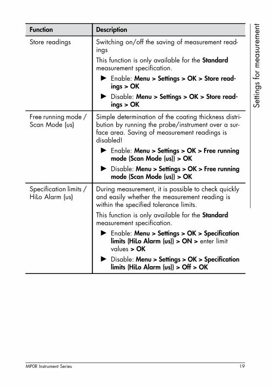
Store readings Switching on/off the saving of measurement read-ingsThis function is only available for the Standard measurement specification.► Enable: Menu > Settings > OK > Store read-
ings > OK
► Disable: Menu > Settings > OK > Store read-ings > OK
Free running mode / Scan Mode (us)
Simple determination of the coating thickness distri-bution by running the probe/instrument over a sur-face area. Saving of measurement readings is disabled!► Enable: Menu > Settings > OK > Free running
mode (Scan Mode (us)) > OK
► Disable: Menu > Settings > OK > Free running mode (Scan Mode (us)) > OK
Specification limits / HiLo Alarm (us)
During measurement, it is possible to check quickly and easily whether the measurement reading is within the specified tolerance limits.This function is only available for the Standard measurement specification.► Enable: Menu > Settings > OK > Specification
limits (HiLo Alarm (us)) > ON > enter limit values > OK
► Disable: Menu > Settings > OK > Specification limits (HiLo Alarm (us)) > Off > OK
Function Description
MP0R Instrument Series 19

Setti
ngs
for m
easu
rem
ent
Block Size / Batch Size (us)
Automatic setting of a group separator after a pre-defined number of individual measurements. Useful, if measurement groups (blocks) will be transferred to a PC for evaluation. Please observe, that aside of the measurements also the group separator must be transferred to the PC, see page 43.
ATTENTION Deletion of all readingsAll stored measurement readings will be deleted when changing the function setting!
This function is only available for the Standard measurement specification.► Enable: Menu > Statistics > OK > Block Size
(Batch Size (us)) > OK > On > OK > setting number of measurement readings > OK
► Disable: Menu > Statistics > OK > Block Size (Batch Size (us)) > OK > Off > OK
i Single Readings A representative measurement reading will be formed by a number of individual measurements. This method is especially well-suited for measure-ments where considerable variability of the meas-urement readings is to be expected.
ATTENTION Deletion of all readingsAll stored measurement readings will be deleted when changing the function setting!
► Enable: Menu > Statistics> OK > i Single Read-ings > OK > On > enter number of individual measurements > OK
Entry: Number of individual measurements (2 to 20)
► Disable: Menu > Statistics> OK > i Single Readings > OK > Off > OK
Function Description
20 MP0R Instrument Series

Setti
ngs
for m
easu
rem
ent
Offset The offset value is automatically subtracted from the actual measurement reading during measurement. This changed value is displayed. Example: When an intermediate coating has a known constant thick-ness, this thickness can be entered as an offset val-ue. The thickness of both coatings is measured, though. The thickness of the top coating is displayed directly by subtracting the offset value from the measurement reading.► Enable: Cal > Offset > OK > set value > OK
Positive offset value: Measurement reading is re-duced by the offset value.Negative offset value: Measurement reading is in-creased by the offset value.► Disable: Cal > Offset > OK > enter value 0.00
> OK
Function Description
MP0R Instrument Series 21

Setti
ngs
for m
easu
rem
ent
Measured variable Setting in which manner the measurement reading should be displayed. The measurement reading can be displayed directly as coating thickness value or as count rate (primary probe signal).
ATTENTION Deletion of all readingsAll stored measurement readings will be deleted when changing the function setting!
► Setting the measured variable: Menu > Super-visor > OK > 159 > OK > Measured variable > OK > selection > OK
SelectionCoating thickness: Display of the coating thickness measurement reading with the set unit. norm. Countrate: With the aid of a calculation, the count rate X of the probe determined during the measurement are normalised to a reference range between XN = 0 = coating thickness 0 and XN = 1 = maximum measurable coating thickness. This means that these normalised count rates are comparable regardless of the particular probe.Countrate: Primary probe signal. Usually, the dis-play of the count rates X serves to establish whether a measurable effect even exists for a special meas-uring application.
Function Description
22 MP0R Instrument Series

Setti
ngs
for m
easu
rem
ent
5.2 Further settings for measurementFunction Description
Change unit ► Select unit: Menu > Settings > OK > Change unit > OK > selection > OK
Selectionµm: Unit of measurement based on the metre as SI base unitmils: Anglo-American unit of measurement for length
Dual mode This function is only available for the DUALSCOPE instrument versions.Selecting whether one or both measurement test methods shall be available for measurement.► Setting: Menu > Settings > OK > Dual mode >
OK > selection > OK
SelectionNF/Fe: On coated magnetic materials can be meas-ured only. The magnetic induction test method is just used for measurement.NC/NF: On coated non-magnetic materials can be measured only. The amplitude sensitive eddy cur-rent test method is just used for measurement.Both: Both measurement test methods are available. The suitable measuring test method is used automat-ically for the current substrate material.
Audible signal Enable/Disable the audible signal that reports the measurement acquisition.► Enable: Menu > Settings > OK > Audible signal
> OK
► Disable: Menu > Settings > OK > Audible signal > OK
MP0R Instrument Series 23
Setti
ngs
for m
easu
rem
ent
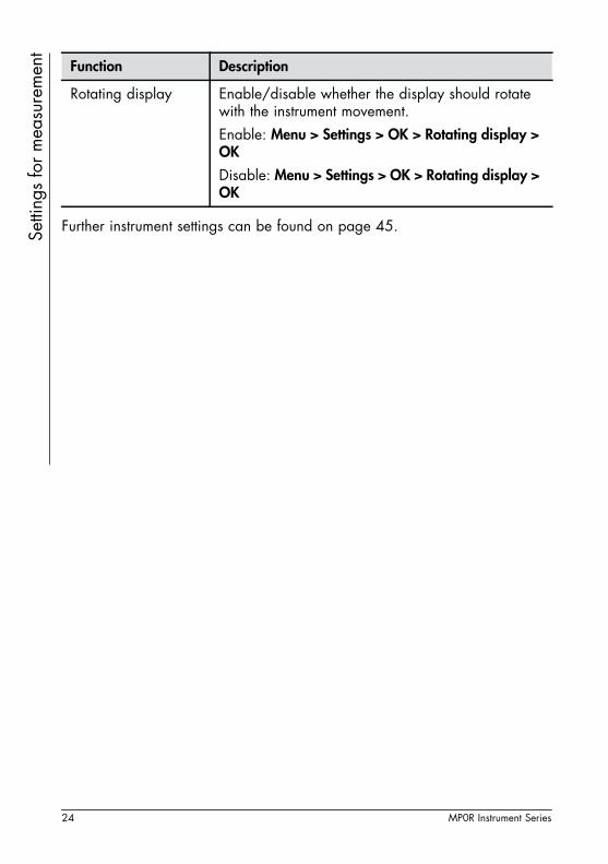
Further instrument settings can be found on page 45.
Rotating display Enable/disable whether the display should rotate with the instrument movement.Enable: Menu > Settings > OK > Rotating display > OK
Disable: Menu > Settings > OK > Rotating display > OK
Function Description
24 MP0R Instrument Series

Taki
ng in
fluen
cing
var
iabl
es in
to a
ccou
nt
6 Taking influencing variables into account The coating thickness measurement is mainly influenced by the following vari-ables:• Physical characteristics of the substrate material of the specimen, such asthe magnetisability (permeability) or electrical conductivity.• The geometric design of the specimen, such as the thickness of the sub-
strate material or curvature of the specimen (e.g. cylindrical shape).• The position of the measuring point on the specimen: distance from the
edge, hole, platform or step.• Surface roughness
For correct measurements of the coating thickness the instrument with the con-nected probe must capture the characteristics of the specimen. This is done with a calibration. For this purpose, the influencing variables are recorded us-ing an uncoated reference part and one or two calibration foils in order to compensate the influences for future measurements.
6.1 Types of calibrations
In calibration, normalisation and calibration are distinguished.
6.1.1 Normalisation
Normalisation is the simplest type of calibration and serves to calibrate the measurement system to a reference point, the substrate material (magnetisable or non-magnetisable and electrically conductive, depending on the test method used). The measurement is done on a reference part that has the same material and shape as the part to be tested. It only consists of the substrate material, in other words without the coating material to be measured. Procedure see page 28.
6.1.2 Calibration
With a calibration, the measurement system is specially adapted to the speci-men characteristics. In calibration, calibration is not only done to the substrate material but also at least to one coating thickness value using a calibration foil. A calibration using the calibration foil included with the scope of supply pro-vides the best measuring accuracy for the entire measurement range. Proce-dure see page 30.
MP0R Instrument Series 25

Taki
ng in
fluen
cing
var
iabl
es in
to a
ccou
nt
6.1.3 Simple CalibrationCalibrating the measurement system with a already coated reference part (cali-bration standard) with known coating thickness. Procedure see page 33.
6.1.4 Master calibration
The master characteristics shows the relationship between the measurement signal of the probe and the coating thickness.A master calibration (factory master calibration) is already performed at the facility of the Helmut Fischer GmbH Institut für Elektronik und Messtechnik with very high precision and at least 8 calibration standards for each specimen ma-terial type. It cannot be deleted or overwritten by the user.You can set up a user master calibration by yourself using 4 till 8 calibration standards. A master calibration set with 4 calibration standards is available as an option. In master calibration, 4 calibration standards must be within pre-scribed coating thickness ranges. These coating thickness ranges are probe specific. Procedure see page 35.
Notes
• Please note, that a Simple Calibration does not pro-vide as good an adjustment for the substrate material as a calibration with an uncoated reference part. The Simple Calibration causes an additional measurement error depending on the coating thickness of the used calibration standard, so that it is not possible to pro-vide a generally applicable value for this additional measurement error.
• If you have no possibility to obtain an uncoated refer-ence part (uncoated substrate material only), then only use the Simple Calibration!
• The Simple Calibration is enabled only for coating thicknesses above 200 μm (7.87 mils)!
26 MP0R Instrument Series

Taki
ng in
fluen
cing
var
iabl
es in
to a
ccou
nt
6.2 Calibration - essential information• Make sure that the measuring point on the reference part has roughly the same position as on the specimen to be actually measured (curvature, dis-tance from the edge, hole, platform and step).
• Generally, the substrate material of your specimen will have different ma-terial properties than those that were taken into account in the factory master calibration (factory pre-calibration). For this reason, it is essential to perform the normalisation or calibration with uncoated reference parts (specimens) from your own production!
• Using 2 calibration foils for calibration is only reasonable, if you need a high accuracy in a certain thickness range. In this case, the thickness val-ues of the two calibration foils limit the coating thickness range.
Note
Perform the calibration carefully! It is the quantity for the accuracy with which the following measurements can be performed. - Measurements can never be more accurate than the calibration!
MP0R Instrument Series 27
Taki
ng in
fluen
cing
var
iabl
es in
to a
ccou
nt
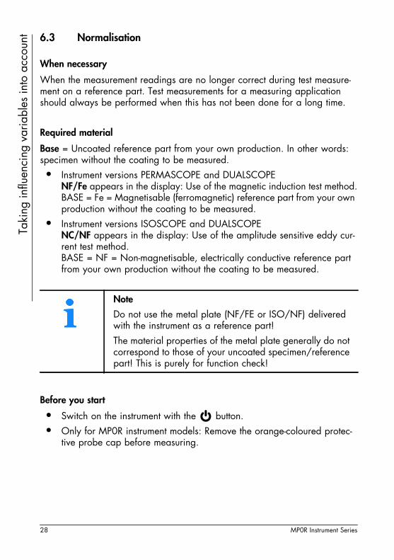
6.3 NormalisationWhen necessary
When the measurement readings are no longer correct during test measure-ment on a reference part. Test measurements for a measuring application should always be performed when this has not been done for a long time.
Required material
Base = Uncoated reference part from your own production. In other words: specimen without the coating to be measured. • Instrument versions PERMASCOPE and DUALSCOPE
NF/Fe appears in the display: Use of the magnetic induction test method.BASE = Fe = Magnetisable (ferromagnetic) reference part from your own production without the coating to be measured.
• Instrument versions ISOSCOPE and DUALSCOPENC/NF appears in the display: Use of the amplitude sensitive eddy cur-rent test method.BASE = NF = Non-magnetisable, electrically conductive reference part from your own production without the coating to be measured.
Before you start
• Switch on the instrument with the button.• Only for MP0R instrument models: Remove the orange-coloured protec-
tive probe cap before measuring.
Note
Do not use the metal plate (NF/FE or ISO/NF) delivered with the instrument as a reference part!The material properties of the metal plate generally do not correspond to those of your uncoated specimen/reference part! This is purely for function check!
28 MP0R Instrument Series

Taki
ng in
fluen
cing
var
iabl
es in
to a
ccou
nt
Call up function, cancel function► Call up function: Cal > Normalization > OK
► Cancel, leave function: ESC
Normalisation - procedure
1. Perform 5 to 10 measurements on the uncoated reference part (= substrate material, specimen without coating). The measurement reading appears on the displays after each measurement. Make sure that the measuring point on the reference part has roughly the same position as on the specimen to be actually measured (curvature, distance from the edge, hole, platform and step).• Delete last measurement reading: Delete
2. Press the multifunctional key OK to complete the normalisation. The message "Normalization finished successfully!" appears in the display.The reference point determined during the normalisation is stored in the instrument.
3. Press the multifunctional key OK to quit the message.The instrument is now ready for measuring.
NoteOnly for DUALSCOPE instrument versions: If measurements are to be done on both types of substrate material (magnetic, non-magnetic), the normalisation procedure must be performed for each type of substrate material (Fe and NF)!
MP0R Instrument Series 29

Taki
ng in
fluen
cing
var
iabl
es in
to a
ccou
nt
6.4 CalibrationWhen necessary
• When the trueness is not observed during measurements on reference parts (e.g. customer standards, reference parts)
• When a normalisation is not sufficient to take the influencing variables into account
Required materials
Base = Uncoated reference part from your own production. In other words: specimen without the coating to be measured.calibration foils from scope of supply. This yields the best measuring accuracy for the entire measurement range. The circle on the foil marks the measurement area.• Instrument versions PERMASCOPE and DUALSCOPE
NF/Fe appears in the display: Use of the magnetic induction test method.Base = Fe = Magnetisable (ferromagnetic) reference part from your own production without the coating to be measured.
• Instrument versions ISOSCOPE and DUALSCOPENC/NF appears in the display: Use of the amplitude sensitive eddy cur-rent test method.Base = NF = Non-magnetisable, electrically conductive reference part from your own production without the coating to be measured.
NoteDo not use the metal plate (NF/FE or ISO/NF) delivered with the instrument as a reference part!The material properties of the metal plate generally do not correspond to those of your uncoated specimen/reference part! This is purely for function check!
30 MP0R Instrument Series

Taki
ng in
fluen
cing
var
iabl
es in
to a
ccou
nt
Before you start
• Switch on the instrument with the key.• Only for MP0R instrument models: Remove the orange-coloured protec-
tive probe cap before measuring.
Call up function, cancel function
► Call up function: Cal > Calibration > OK
► Cancel, leave function: ESC
Calibration - procedure
1. Perform 5 to 10 measurements on the uncoated reference part (= substrate material, specimen without coating). The measurement reading appears on the displays after each measurement.Make sure that the measuring point on the reference part has roughly the same position as on the specimen to be actually measured (curvature, distance from the edge, hole, platform and step).• Delete last measurement reading: Delete
2. Press the multifunctional key OK to complete the normalisation. The message "Please measure several times: 1. CAL-rated value" or "Please measure several times: 75.3 μm" (2.96 mils, example) appears in the display.
NoteBe carefully with the calibration foils. Do not soil, bend or scratch the calibration foils! Replace soiled, bent, scratched or cracked calibration foils or whose with strong indentations. In particular foils with thicknesses of less than 50 μm (1.97 mils) are subject to rapid wear.Recommendation: Replace the calibration foils after no more than 100 to 200 measurements!
MP0R Instrument Series 31

Taki
ng in
fluen
cing
var
iabl
es in
to a
ccou
nt
3. Place the calibration foil on the uncoated reference part.4. Perform 5 to 10 measurements on the calibration foil. To do this, place the probe on the foil within the circle each time. The measurement reading appears on the displays after each measurement.Make sure that the measuring point on the reference part has roughly the same position as on the specimen to be actually measured (curvature, distance from the edge, hole, platform and step).• Delete last measurement reading: Delete
5. Press the multifunctional key OK to quit the measurement and to set up the CAL-rated value.
6. Use the multifunctional keys to set the rated value of the calibration foil, e.g. "71.9 μm" (2.83 mils). The rated value is printed on the calibra-tion foil.
7. Remove the calibration foil from the reference part. Keep the calibration foils carefully.
8. Press the multifunctional key OK to complete the calibration with the first calibration foil. The message "Please measure several times: 2. CAL-rated value" or "Please measure several times: 352 μm" (13.85 mils, example) appears in the display. You have two choices:• You can calibrate with a further calibration foil on the uncoated refer-
ence part. For this purpose repeating steps 3. to 7. with the second calibration foil and continue then with step 9. .
• Complete the calibration as described in the following steps.9. Press the multifunctional key OK to complete the calibration. The message
"Calibration finished successfully!" appears in the display.The reference points determined during the calibration will be stored in the instrument.
Calibration foil
The circle of the calibration foil must be on the marked measurement area of the un-coated reference part.
Foil thickness,rated valueWarranty error limit
Article number of the calibration foil
Uncoated reference part
32 MP0R Instrument Series
Taki
ng in
fluen
cing
var
iabl
es in
to a
ccou
nt
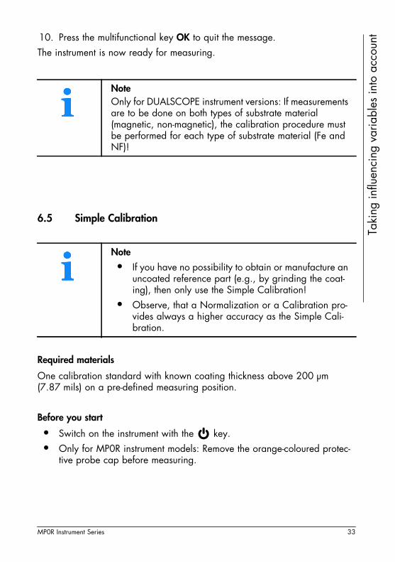
10. Press the multifunctional key OK to quit the message.The instrument is now ready for measuring.6.5 Simple Calibration
Required materials
One calibration standard with known coating thickness above 200 μm (7.87 mils) on a pre-defined measuring position.
Before you start
• Switch on the instrument with the key.• Only for MP0R instrument models: Remove the orange-coloured protec-
tive probe cap before measuring.
NoteOnly for DUALSCOPE instrument versions: If measurements are to be done on both types of substrate material (magnetic, non-magnetic), the calibration procedure must be performed for each type of substrate material (Fe and NF)!
Note
• If you have no possibility to obtain or manufacture an uncoated reference part (e.g., by grinding the coat-ing), then only use the Simple Calibration!
• Observe, that a Normalization or a Calibration pro-vides always a higher accuracy as the Simple Cali-bration.
MP0R Instrument Series 33
Taki
ng in
fluen
cing
var
iabl
es in
to a
ccou
nt
Call up function, cancel function► Call up function: Cal > Simple Calibration > OK
► Cancel, leave function: ESC
Simple Calibration - procedure
1. Perform 5 to 10 measurements at the measuring position on the calibra-tion standard. The measurement reading appears on the displays after each measurement.• Delete last measurement reading: Delete
2. Press the multifunctional key OK to quit the measurement 3. Use the multifunctional keys to set the rated value of the calibration
standard, e.g., "253 μm" (9.96 mils). 4. Press the multifunctional key OK to complete the Simple Calibration. The
message "Calibration finished successfully!" appears in the display.The reference points determined during the calibration will be stored in the instrument.
5. Press the multifunctional key OK to quit the message. Observe the following note.
The instrument is now ready for measuring.
NoteOnly for DUALSCOPE instrument versions: If measurements are to be done on both types of substrate material (magnetic, non-magnetic), the calibration procedure must be performed for each type of substrate material (Fe and NF)!
34 MP0R Instrument Series

Taki
ng in
fluen
cing
var
iabl
es in
to a
ccou
nt
6.6 User master calibrationRequired materials
• Uncoated reference part that has the same substrate material and geom-etry as the specimen to be actually measured
• Master calibration foils set (optional accessory)
Before you start
• Switch on the instrument with the key.• Only for MP0R instrument models: Remove the orange-coloured protec-
tive probe cap before measuring.
Call up function, cancel function
► Call up function: Menu > Supervisor > OK > 159 > OK > Master Calibra-tion > OK
► Cancel, leave function: ESC
NoteA user master calibration (referred to as only master cali-bration in the following) may only be performed by an experienced operator.
ATTENTION Deletion of the Normalization/CalibrationAfter a master calibration has been completely performed, the Normalizations and Calibrations are automatically deleted and must be performed again!
The master characteristic can only be determined during a master calibration when suitable calibration standards are used. You can order a master calibration foil set suitable for your instrument from FISCHER or from your local FISCHER representative.
MP0R Instrument Series 35

Taki
ng in
fluen
cing
var
iabl
es in
to a
ccou
nt
User master calibration - procedure1. Perform 5 to 10 measurements on an uncoated reference part that has the same substrate material and geometry as the specimen to be actually measured.Make sure that the measuring point on the reference part has roughly the same position as on the specimen to be actually measured (curvature, distance from the edge, hole, platform and step).• Delete last measurement reading: Delete
2. Press the multifunctional key OK to complete the normalisation. The message "Please measure several times: 1.CAL-rated value" appears in the display.
3. Place the calibration foil (1) on the uncoated reference part.
4. Perform 5 to 10 measurements on the calibration foil. To do this, place the probe on the foil within the circle each time. The measurement reading appears on the displays after each measurement.Make sure that the measuring point on the reference part has roughly the same position as on the specimen to be actually measured (curvature, distance from the edge, hole, platform and step).• Delete last measurement reading: Delete
5. Press the multifunctional key OK to quit the measurement and to set up the CAL-rated value.
6. Use the multifunctional keys to set the rated value of the calibration foil, e.g. "9.73 μm" (0.38 mils). The rated value is printed on the calibra-tion foil.
7. Remove the calibration foil from the reference part. Keep the calibration foils carefully.
8. Press the multifunctional key OK to complete the calibration with the 1st calibration foil. The message "Please measure several times: 2. CAL-rated value" appears in the display.
Calibration foil
The circle of the calibration foil must be on the marked measuring area of the un-coated reference part.
Foil thickness,rated valueWarranty error limit
Article number of the calibration foil
Uncoated reference part
36 MP0R Instrument Series

Taki
ng in
fluen
cing
var
iabl
es in
to a
ccou
nt
Repeat the steps 3. to 7. till all calibration foils are measured (minimum 4, maximum 8).9. Press the multifunctional button OK to complete the user master calibra-tion. The message "Master calibration finished successfully!" appears in the display.The reference points determined during the user master calibration will be stored in the instrument.
10. Press the multifunctional key OK to quit the message.
The instrument is now ready for measuring.
6.7 Lock the calibration functions
Protect your normalisation, calibration or user master calibration against unau-thorised overwriting.► Enable function: Menu > Supervisor > OK > 159 > OK > Lock Calibration
(Cal Lock (us)) > OK
A check mark next to Lock Calibration (Cal Lock (us)) shows the active locking mode.The main menu Cal no longer appears in the display.
6.8 Unlock the calibration functions
► Disable function: Menu > Supervisor > OK > 159 > OK > Lock Calibration (Cal Lock (us)) > OK
NoteOnly for DUALSCOPE instrument versions: If measurements are to be done on both types of substrate material (magnetic, non-magnetic), the calibration procedure must be performed for each type of substrate material (Fe and NF)!
MP0R Instrument Series 37
38 MP0R Instrument Series
Eval
uatio
n 7 Evaluation
The evaluation is always done with all measurement readings in the measure-ment data memory.
Before you start
• At least two measurement readings are required for an evaluation.• Switch on the instrument with the key.
Procedure
1. Call up the Evaluation menu via the multifunctional key Res. The following options are available in the menu Evaluation:• Result: Shows a clear evaluation• Single Readings: Shows all stored measurement readings
2. Select the desired view with the multifunctional keys and confirm with OK.
3. To exit the evaluation, press the multifunctional key Back.
7.1 Res > Result - Description of the statistical characteristics
Display Description
n Number of all measurement readings stored in the instrument
th. Average (= arithmetic mean value, sum of all measurement readings stored in the instrument divided by the number of all measurements readings)
s Standard deviation (= quantity for the variation of the meas-urement readings stored in the instrument around their com-mon mean value)
min Lowest measurement reading stored in the instrument
max Highest measurement reading stored in the instrument

Del
etin
g
8 Deleting8.1 Deleting measurement readings
Delete last measurement reading
► Start delete function: Del > Delete Last Reading > OK
Delete current block
Delete all measurement readings until next group separator (closed block):► Start delete function: Del > Delete Current Block > OK > Yes
► Cancel delete function: Del > Delete Current Block > OK > No
Delete all measurement readings
Delete all as yet stored measurement readings:► Start delete function: Del > Delete All Readings > OK > Yes
► Cancel delete function: Del > Delete All Readings > OK > No
8.2 Deleting the calibration
► Delete calibration: Cal > Delete Calibration > OK
The Simple Calibration or the Calibration will be deleted. The function Delete Calibration is only available after a Calibration or Simple Calibra-tion has been performed.
8.3 Deleting the (user) master calibration
► Delete (user) master calibration: Menu > Supervisor > OK > 159 > Delete Master Cal. > OK
The function Delete Master Cal. is only available after a User Master Cali-bration has been performed.
MP0R Instrument Series 39

Del
etin
g
8.4 Resetting the instrument to the factory settingsIt can happen that the instrument does not measure correctly despite calibra-tion. In such a case, we recommend resetting the instrument to the factory cali-bration or factory settings, in order to obtain a defined initial state again. With a subsequent new normalisation or calibration, it will generally be possible to measure correctly again.
► Start function: Menu > Supervisor > OK > 159 > OK > Initialization > OK > Yes > OK
ATTENTION Deletion of all measurement readings and calibrations
If the instrument is reset to the factory settings, all measure-ment readings, settings and calibrations are deleted!
Note
Before you can make a measurement, you must perform a normalisation!► Perform a normalisation, see page 28.
40 MP0R Instrument Series

Dat
a tra
nsfe
r
9 Data transferYou can transfer measurement readings and statistical characteristics to a PC using the USB port.• USB port: The data is transferred directly from the instrument to the com-
puter via an USB cable connection. The necessary USB driver and the USB connection cable are included in the scope of supply of the instru-ment.
For further processing of the data transferred from the instrument commercially as well as internally developed data processing programs can be used. Infor-mation on the data import and further processing can be found in the corre-sponding program manuals.
9.1 Preparation for the data transfer
9.1.1 Establish a USB connection
1. Install the USB driver on the PC. Use the support CD in the scope of supply for this. Select MP0R in the CD menu. Click the Install command button.The USB driver is automatically installed on your PC.
2. Install the FISCHER DataCenter evaluation software from the support CD. FISCHER DataCenter is a convenient software for transferring, evaluating and printing measurement readings. Close the window of the support CD when the installation is complete.
3. Connect the instrument to a USB port on the PC using the USB cable in the scope of supply.
9.2 Transferring measurement readings to the PC
• During measurement, data transfer in real time, page 42• After measurement, data transfer of all measurement readings that are al-
MP0R Instrument Series 41

Dat
a tra
nsfe
r
ready in the measurement data memory of the instrument, page 42You can transfer data from the instrument to the PC into the FISCHER Data-Center evaluation software for example.9.2.1 Transferring individual measurement readings to the FISCHER DataCenter
To transfer individual measurement readings to the FISCHER DataCenter automatically and in real time, proceed as follows:
1. Switch on the instrument using the key.2. Only for MP0R instrument models: Remove the orange-coloured protec-
tive probe cap before measuring.3. Connect the instrument to the PC. Use the USB cable in the scope of
supply for this.4. Start the FISCHER DataCenter on the PC.5. Add a new device, call up an already set up readings file or create a
new readings file. (Proceed as described in the FISCHER DataCenter instruction.)
6. Start the online measurement in the FISCHER DataCenter. (Proceed as described in the FISCHER DataCenter instruction.)
7. Now record measurement readings with the instrument. These are auto-matically displayed in the FISCHER DataCenter evaluation software and are available for further evaluations.
9.2.2 Transfer all recorded measurement readings to the FISCHER DataCenter
To transfer all stored measurement readings to the FISCHER DataCenter, proceed as follows:
1. Switch on the instrument using the key.2. Connect the instrument to the PC. Use the USB cable in the scope of
supply for this.3. Start the FISCHER DataCenter on the PC.
42 MP0R Instrument Series
Dat
a tra
nsfe
r
4. FISCHER DataCenter: Add a new device, call up an already set up read-ings file or create a new readings file. (Proceed as described in the FISCHER DataCenter instruction.)5. FISCHER DataCenter: Get measurements from the measurement data memory of the instrument. (Proceed as described in the FISCHER Data-Center instruction.)The FISCHER DataCenter transfer all measurement readings from the measurement data memory of the instrument. The FISCHER DataCenter recognizes automatically the block size (batch size (us)) set in the instru-ment and take it into account for the data transfer.
9.2.3 Data transfer to third-party programs
Commercial as well as internally developed data processing programs can be used for further processing of the data output by the instrument, e.g. PCDATEX for importing measurement readings to Microsoft Excel. Information on import-ing and further processing data with these programs can be found in the man-uals of these programs, if needed.
Settings for the data transmission in the instrument
1. Switch on the instrument using the key.2. Settings for the data transmission: Menu > Settings > OK > Output > OK
> selection > OK.SelectionSingle Readings: Each measurement reading is automatically transferred to the PC during the measurement and also stored in the measurement data memory of the instrument.Mean values:
Each measurement reading is stored in the measurement data memory of the instrument. The mean values of each block only are transferred to the PC.
3. Enable group separator: Menu > Settings > OK > Group separator > OK. A check mark indicates, that the group separator is also transferred.
The data transfer is only possible if the function block size is enabled before starting measurement. Setting see page 20.
MP0R Instrument Series 43
Dat
a tra
nsfe
r
The setting is only necessary, if a block size (batch size (us)) has been set before measurement (see page 20 and 17) and the measurement blocks are to be transferred.4. Transfer the measurement readings to the PC: Res > OK > Send Readings > OK.All measurement readings are transferred to the FISCHER DataCenter and are available for further evaluations. Is a block size (batch size (us)) set before starting measurement the group separators are transmitted automatically as division for the measurement blocks.
Disable the transfer of the group separator
► Disable group separator: Menu > Settings > OK > Group separator > OK.
44 MP0R Instrument Series

Dis
play
and
mea
sure
men
t val
ue d
ispl
ay
10 Display and measurement value displayAll instrument functions about the view in the display are listed in this chapter. A check mark indicates that the function is active.
Function Description
Language ► Select instrument language: Menu > Settings > OK > Language > OK > select language > OK
Display statistics Additional display for the measurement reading.► Select additional display: Menu > Statistics > OK
> Display statistics > OK > selection > OK
SelectionShow std dev: Displays mean value (th.) and standard deviation (s) additionally to the measurement readingShow number: Displays mean value (th.) and the num-ber of the measurement reading (n) additionally to the measurement readingNone: No additional display to the measurement reading. Display of the measurement reading only.
Decimal places Number of decimal places after the decimal point with which the measurement reading is to be dis-played.Set decimal places: Menu > Settings > OK > Decimal places > OK > selection > OK
Selectionlow: 0.9 / 9.9 / 99 / 999 / 9999medium: 0.99 / 9.9 / 99, 9 / 999 / 9999high: 0.999 / 9.99 / 99.99 / 999.9 / 9999
Contrast ► Set display contrast: Menu > Settings > OK > Contrast > OK > change contrast value > OK. Standard: Contrast value 50.
MP0R Instrument Series 45
Dis
play
and
mea
sure
men
t val
ue d
ispl
ay
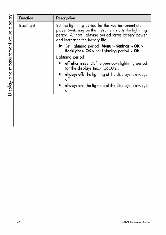
Backlight Set the lightning period for the two instrument dis-plays. Switching on the instrument starts the lightning period. A short lightning period saves battery power and increases the battery life.► Set lightning period: Menu > Settings > OK >
Backlight > OK > set lightning period > OK.Lightning period• off after n sec: Define your own lightning period
for the displays (max. 3600 s).• always off: The lighting of the displays is always
off.• always on: The lighting of the displays is always
on.
Function Description
46 MP0R Instrument Series

Mal
func
tions
- W
hat s
houl
d yo
u do
?
11 Malfunctions - What should you do?Display Possible causes Remedy
Darkdisplay
• Instrument is switched off
► Press the key to switch on the instrument.
• The protective foil is still in the battery com-partment, which pre-vents the instrument from being switched on.
► Remove the protective foil from the battery compart-ment before use.
• The USB port is in an undefined state.
► Remove the batteries and place them in the battery compartment again. Press the key to switch on the instrument.
E001 • Internal instrument er-ror
► Switch the instrument off and then on again with the
key. If this error occurs repeatedly: Contact customer service depart-ment.
- - - - - - • Free running mode (scan mode (us)) is ac-tive
► Switch off the free running mode (scan mode (us)) to return to the set measure-ment mode.
E004 • The measurement data memory is full
► Delete all measurement readings from the measure-ment data memory.
E006or_ _ _ _
• Measurement reading is outside the measure-ment rangeCause: The coating is too thick.
The instrument can only measure coating thicknesses that are with-in its measurement range. ► Measure on specimens with
a smaller coating thickness.
MP0R Instrument Series 47

Mal
func
tions
- W
hat s
houl
d yo
u do
?
• Faulty measurement ► Perform the measurement carefully (e.g. do not hover with the instrument/probe over the specimen, only lift up the instrument/probe from the specimen after the measurement reading has been accepted (is indicated by a brief acoustic signal in the standard setting)).
• Wrong substrate mate-rial of the specimen
► Only measure on speci-mens with a substrate mate-rial that matches the displayed measuring method.NF/Fe display: Substrate material made of ferromag-netic metal (iron, steel).NC/NF display: Substrate material made of non-magnetic metal.
• Incorrect normalisa-tion or calibration
► Perform the normalisation or calibration again. Perform the normalisation or calibration carefully! The normalisation or calibration determines the accuracy of the following measure-ments. Measurements can never be more accurate than the normalisation or calibra-tion!
Display Possible causes Remedy
48 MP0R Instrument Series

Mal
func
tions
- W
hat s
houl
d yo
u do
?
E007 • An outlier has been de-tected during the nor-malisation or calibra-tion.Cause: Measurements on the reference part were not performed correctly.
► Repeat measurements on the reference part carefully (e.g. do not hover the instru-ment/probe over the spec-imen, only lift up the instrument/probe from the specimen after the measure-ment reading has been accepted).
• Measurements were performed on the cali-bration foil instead of the uncoated reference part (Base)
► Repeat measurements on the uncoated reference part (Base).
• Measurements on a damaged calibration foil
► Replace the calibration foil and repeat the measure-ments on the new calibra-tion foil.
• Instrument/probe was not placed vertically on the surface during measurement
► Always place the instru-ment/probe on the surface quickly and vertically.
E011 • Calibration cannot be completed.Cause: The measure-ment not performed correctly.
► Repeat calibration carefully (e.g. do not hover the probe over the reference part before or after the measurement; maintain minimum lifting distance of 25 mm (0.98 mils)!)
• Cause: Calibration foils used that do not have the required coat-ing thickness or are de-fective
► Repeat the calibration with suitable and intact calibra-tion foils.
Display Possible causes Remedy
MP0R Instrument Series 49

Mal
func
tions
- W
hat s
houl
d yo
u do
?
• Cause: Normalisation preformed on calibra-tion foil instead of un-coated specimen
► Repeat calibration and perform normalisation on uncoated specimen in doing so.
E012 • Calibration foils meas-ured in the wrong or-der during calibration (foil 1 mixed up with foil 2), and foil thick-ness not appropriately adjusted with multifunc-tional keys
► Repeat calibration and measure the foils in the correct order in doing so. Observe the Cal-rated value in the display.
E030 • Probe content do not matches the test value
► Contact customer service department.
E033 • Internal write/read er-ror.
► Contact customer service department.
E035 • No measurement read-ing can be calculated, because no normalisa-tion has been per-formed on the current substrate material.
► Perform a normalisation.
E039 • Defective factory cali-bration
► Contact customer service department.
W002 • Memory defective ► Contact customer service department.
W003 • Instrument has automat-ically corrected an in-correct setting
Display Possible causes Remedy
50 MP0R Instrument Series

Mal
func
tions
- W
hat s
houl
d yo
u do
?
W004 • A process has been aborted (e.g. calibra-tion aborted).
► Repeat process if neces-sary.
W005 • Two-point calibration performed with calibra-tion foils whose coat-ing thicknesses are not far enough apart (is taken as one-point cali-bration).
► Repeat the calibration with suitable calibration foils. The difference of the stand-ardised counting rates XN of the two calibration foils must be greater than 0.1:
XN = XNCalibration foil2 - XNCalibration
foil1
Xn > 0.1
Display Possible causes Remedy
MP0R Instrument Series 51

Tech
nica
l dat
a
12 Technical dataGeneral technical data - valid for all models
Weight MP0R modelsMP0R-FP models
ca. 137 g with two batteries, ca. 184 g with two batteries
Cable length MP0R-FP models only: 80 cm (31.5 inches)
Dimensions W x D x H
mm: 64 x 28 x 85 inches: 2.51 x 1.1 x 3.35
Voltage supply 2 x batteries/accus, Batteries: Mignon, Alkaline, LR6 - AA, 1.5 V Accus: Mignon, NiMH, HR6 - AA, 1.2 V
Power consumption Max. 0.2 Watt
Ambient tempera-ture
0 ... +40 °C / +32 ... +104 °F during operation+5 ... +60 °C (+41 ... +140 °F) storage temperature
Relative humidity 30 ... 90 % (non-condensing)
USB port 2.0 compatible, mini type B standard socket, for con-nection to a PC.
Data memory Storage of max. 10,000 individual measurementsThe memory content is preserved even when there is no voltage supply.
Measurement inter-val
More than 70 measurements per minute
52 MP0R Instrument Series
Tech
nica
l dat
a
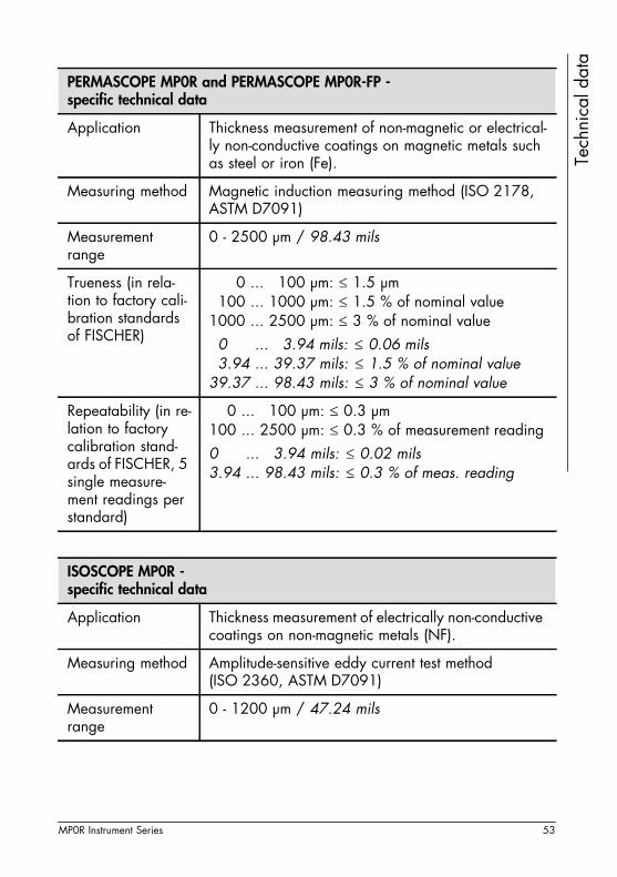
PERMASCOPE MP0R and PERMASCOPE MP0R-FP - specific technical data
Application Thickness measurement of non-magnetic or electrical-ly non-conductive coatings on magnetic metals such as steel or iron (Fe).
Measuring method Magnetic induction measuring method (ISO 2178, ASTM D7091)
Measurement range
0 - 2500 μm / 98.43 mils
Trueness (in rela-tion to factory cali-bration standards of FISCHER)
1000 ... 1100 μm: ≤ 1.5 μm 1100 ... 1000 μm: ≤ 1.5 % of nominal value1000 ... 2500 μm: ≤ 3 % of nominal value30 .94... 33.94 mils: ≤ 0.06 mils33.94 ... 39.37 mils: ≤ 1.5 % of nominal value39.37 ... 98.43 mils: ≤ 3 % of nominal value
Repeatability (in re-lation to factory calibration stand-ards of FISCHER, 5 single measure-ment readings per standard)
100 ... 2100 μm: ≤ 0.3 μm 100 ... 2500 μm: ≤ 0.3 % of measurement reading0.94 ... 93.94 mils: ≤ 0.02 mils3.94 ... 98.43 mils: ≤ 0.3 % of meas. reading
ISOSCOPE MP0R - specific technical data
Application Thickness measurement of electrically non-conductive coatings on non-magnetic metals (NF).
Measuring method Amplitude-sensitive eddy current test method (ISO 2360, ASTM D7091)
Measurement range
0 - 1200 μm / 47.24 mils
MP0R Instrument Series 53

Tech
nica
l dat
a
Trueness (in rela-tion to factory cali-bration standards of FISCHER)
270 ... 1270 μm: ≤ 1 μm 270 ... 1250 μm: ≤ 1.5 % of nominal value250 ... 1000 μm: ≤ 3 % of nominal value0.76 ... 32.76 mils: ≤ 0.04 mils2.76 ... 39.84 mils: ≤ 1.5 % of nominal value9.84 ... 39.37 mils: ≤ 3 % of nominal value
Repeatability (in re-lation to factory calibration stand-ards of FISCHER, 5 single measure-ment readings per standard)
50 ... 1050 μm: ≤ 0.25 μm 50 ... 1000 μm: ≤ 0.5 % of measurement reading0.97 ... 31.97 mils: ≤ 0.01 mils1.97 ... 39.37 mils: ≤ 0.5 % of meas. reading
DUALSCOPE MP0R, DUALSCOPE MP0R-FP and DUALSCOPE MP0R-FPW - specific technical data
Application NF/Fe: Measurement of non-magnetic or electrically non-conductive coatings on magnetic metals such as steel or iron (Fe)andNC/NF: Electrically non-conductive coatings on non-magnetic metals (NF).• In the default setting, the substrate material un-
der the coating is automatically identified when the instrument/probe is placed on it, and the in-strument automatically selects the appropriate measuring method.
• These instrument models are perfectly suited for measurements on rough surfaces.
Measuring methods
Magnetic induction test method (ISO 2178, ASTM D7091) and amplitude-sensitive eddy current test method (ISO 2360, ASTM D7091)
ISOSCOPE MP0R - specific technical data
54 MP0R Instrument Series

Tech
nica
l dat
a
Measurement ranges
Substrate material Fe: 0 - 2000 μm / 0 ... 78.74 milsSubst. material NF: 0 - 2000 μm / 0 ... 78.74 mils
Trueness (in rela-tion to factory cali-bration standards of FISCHER)
Substrate material Fe:1070 ... 1075 μm: ≤ 1.5 μm 1075 ... 1000 μm: ≤ 2 % of nominal value1000 ... 2000 μm: ≤ 3 % of nominal value30.95 ... 32.95 mils: ≤ 0.06 mils32.95 ... 39.37 mils: ≤ 2 % of nominal value39.37 ... 78.74 mils: ≤ 3 % of nominal value
Trueness (in rela-tion to factory cali-bration standards of FISCHER)
Substrate material NF: 1050 ... 1050 μm: ≤ 1 μm 1050 ... 1000 μm: ≤ 2 % of nominal value1000 ... 2000 μm: ≤ 3 % of nominal value30.97 ... 31.97 mils: ≤ 0.04 mils31.97 ... 39.97 mils: ≤ 2 % of nominal value39.97 ... 78.74 mils: ≤ 2 % of nominal value
Repeatability (in re-lation to factory calibration stand-ards of FISCHER, 5 single measure-ment readings per standard)
Substrate material Fe:50 ... 2050 μm: ≤ 0.25 μm50 ... 2000 μm: ≤ 0.5 % of measurement reading0.97 ... 71.97 mils: ≤ 0.01 mils1.97 ... 78.74 mils: ≤ 0.5 % of meas. reading
Substrate material NF: 100 ... 2100 μm: ≤ 0.5 μm 100 ... 2000 μm: ≤ 0.5 % of measurement reading0.94 ... 73.94 mils: ≤ 0.02 mils3.94 ... 78.74 mils: ≤ 0.5 % of meas. reading
DUALSCOPE MP0R, DUALSCOPE MP0R-FP and DUALSCOPE MP0R-FPW - specific technical data
MP0R Instrument Series 55

Tech
nica
l dat
a
DUALSCOPE MP0RH-FP - specific technical data
Application NF/Fe: Measurement of non-magnetic or electrically non-conductive coatings (NF) on magnetic metals such as steel or iron (Fe)andNC/NF: Measurement of electrically non-conductive coatings (NC) on non-magnetic metals (NF).• In the default setting, the substrate material un-
der the coating is automatically identified when the instrument/probe is placed on it, and the in-strument automatically selects the appropriate measuring method.
Measuring meth-ods
Magnetic (ISO 2178, ASTM D7091) and amplitude-sensitive eddy current test method (ISO 2360, ASTM D7091)
Measurement rang-es
Substrate material Fe: 0 - 7000 μm / 275.59 milsSubstrate material NF: 0 - 2500 μm / 98.43 mils
Trueness (in rela-tion to factory cali-bration standards of FISCHER)
Substrate material Fe:3150 ... 3150 μm: ≤ 5 μm3150 ... 3000 μm: ≤ 3 % of nominal value3000 ... 6000 μm: ≤ 5 % of nominal value150.91 ... 115.91 mils: ≤ 0.20 mils115.91 ... 118.11 mils: ≤ 3 % of nominal value118.11 ... 236.22 mils: ≤ 5 % of nominal value
Substrate material NF: 1050 ... 1050 μm: ≤ 1 μm 1050 ... 1000 μm: ≤ 2 % of nominal value1000 ... 2200 μm: ≤ 3 % of nominal value30.97 ... 31.97 mils: ≤ 0.04 mils31.97 ... 39.97 mils: ≤ 2 % of nominal value39.97 ... 86.61 mils: ≤ 3 % of nominal value
56 MP0R Instrument Series

Tech
nica
l dat
a
Repeatability (in re-lation to factory calibration stand-ards of FISCHER, 5 single measure-ment readings per standard)
Substrate material Fe:200 ... 6200 μm: ≤ 2 μm200 ... 6000 μm: ≤ 1 % of measurement reading0.87 ... 237.87 mils: ≤ 0.08 mils7.87 ... 236.22 mils: ≤ 1 % of measurement reading
Substrate material NF: 1050 ... 1050 μm: ≤ 0.5 μm 1050 ... 1000 μm: ≤ 1 % of measurement reading1000 ... 2200 μm: ≤ 1.5 % of measurement reading30.97 ... 31.97 mils: ≤ 0.02 mils31.97 ... 39.97 mils: ≤ 1 % of measurement reading39.97 ... 86.61 mils: ≤ 1.5 % of meas. reading
DUALSCOPE MP0RH-FP - specific technical data
MP0R Instrument Series 57
58 MP0R Instrument Series
Ord
erin
g in
form
atio
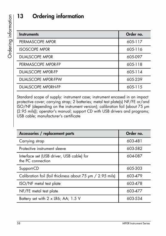
n 13 Ordering information
Standard scope of supply: instrument case; instrument encased in an impact protective cover; carrying strap; 2 batteries; metal test plate(s) NF/FE or/and ISO/NF (depending on the instrument version); calibration foil (about 75 μm (2.95 mils)); operator's manual; support CD with USB drivers and programs; USB cable; manufacturer's certificate
Instruments Order no.
PERMASCOPE MP0R 605-117
ISOSCOPE MP0R 605-116
DUALSCOPE MP0R 605-097
PERMASCOPE MP0R-FP 605-118
DUALSCOPE MP0R-FP 605-114
DUALSCOPE MP0R-FPW 605-239
DUALSCOPE MP0RH-FP 605-115
Accessories / replacement parts Order no.
Carrying strap 603-481
Protective instrument sleeve 603-582
Interface set (USB driver, USB cable) for the PC connection
604-087
Support-CD 605-303
Calibration foil (foil thickness about 75 μm / 2.95 mils) 603-479
ISO/NF metal test plate 603-478
NF/FE metal test plate 603-477
Battery set with 2 x LR6; AA; 1.5 V 603-534

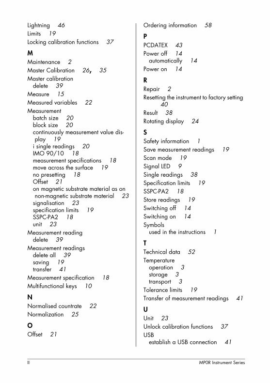
Index
AAmbient conditions 3Areas of application 5Audible signal 23Automatic rotating display 7Automatic switch-off 14
BBacklight 46Batch Size 20Block
delete current block 39Block Size 20
CCalibration 25
cancel locking 37delete 39delete (user) master calibration 39locking 37Master Calibration 35
Change unit 23Coating thickness 22Contrast 45Countrate 22
DData transfer 41
establish a USB connection 41mean values 43preparation 41ringle readings 43third-party programs 43
Decimal places 45Delete
(user) maszer calibration 39all measurement readings 39calibration 39current Block 39last measurrment reading 39Offset 21
user instrument setting 40Display
contrast 45decimal places 45lightning 46rotating 24show additional mean value and num-bers of measurement readings 45
show additional mean value and standard deviation 45
Display statistics 45Dual mode 23
EElectrical equipment, safety information
2Enter block size 20Evaluation 38
FFactory setting
reset the instrument to factory setting 40
FISCHER DataCenter 42Free running mode 19
GGroup separator
set automatically 20
HHiLo Alarm 19
Ii Single Readings 20IMO 90/10 18Instrument
automatic switch-off 14intended use 2
Instrument parts 6Intended use 2LLanguage 45
MP0R Instrument Series I
Lightning 46Limits 19Locking calibration functions 37
MMaintenance 2Master Calibration 26, 35Master calibration
delete 39Measure 15Measured variables 22Measurement
batch size 20block size 20continuously measurement value dis-play 19
i single readings 20IMO 90/10 18measurement specifications 18move across the surface 19no presetting 18Offset 21on magnetic substrate material as on non-magnetic substrate material 23
signalisation 23specification limits 19SSPC-PA2 18unit 23
Measurement readingdelete 39
Measurement readingsdelete all 39saving 19transfer 41
Measurement specification 18Multifunctional keys 10
NNormalised countrate 22Normalization 25
OOffset 21
Ordering information 58
PPCDATEX 43Power off 14
automatically 14Power on 14
RRepair 2Resetting the instrument to factory setting
40Result 38Rotating display 24
SSafety information 1Save measurement readings 19Scan mode 19Signal LED 9Single readings 38Specification limits 19SSPC-PA2 18Store readings 19Switching off 14Switching on 14Symbols
used in the instructions 1TTechnical data 52Temperature
operation 3storage 3transport 3
Tolerance limits 19Transfer of measurement readings 41
UUnit 23Unlock calibration functions 37USB
establish a USB connection 41
II MP0R Instrument Series
WWarnings, indication 1XX 22Xn 22
MP0R Instrument Series III


www.helmut-fischer.comwww.helmut-fischer.com
Coating Thickness Material Analysis Microhardness Material Testing