Performance Rating of Commercial and Industrial...
18
2017 Standard for Performance Rating of Commercial and Industrial Humidifiers AHRI Standard 640 (I-P)
Transcript of Performance Rating of Commercial and Industrial...
2017 Standard for
Performance Rating of Commercial and Industrial Humidifiers
AHRI Standard 640 (I-P)
Price $10.00 (M) $20.00 (NM) © Copyright 2017, by Air-Conditioning, Heating, and Refrigeration Institute Printed in U.S.A. Registered United States Patent and Trademark Office
IMPORTANT
SAFETY DISCLAIMER
AHRI does not set safety standards and does not certify or guarantee the safety of any
products, components or systems designed, tested, rated, installed or operated in accordance
with this standard/guideline. It is strongly recommended that products be designed,
constructed, assembled, installed and operated in accordance with nationally recognized
safety standards and code requirements appropriate for products covered by this
standard/guideline.
AHRI uses its best efforts to develop standards/guidelines employing state-of-the-art and
accepted industry practices. AHRI does not certify or guarantee that any tests conducted under
its standards/guidelines will be non-hazardous or free from risk.
Note:
This standard supersedes ANSI/AHRI Standard 640-2005.
For SI ratings, see AHRI Standard 641 (SI)-2017.
TABLE OF CONTENTS
SECTION PAGE
Section 1. Purpose .................................................................................................................. 1
Section 2. Scope ..................................................................................................................... 1
Section 3. Definitions............................................................................................................. 1
Section 4. Test Requirements ................................................................................................ 3
Section 5. Rating Requirements ............................................................................................. 4
Section 6. Minimum Data Requirements for Published Ratings ........................................... 5
Section 7. Marking and Nameplate Data ............................................................................... 6
Section 8. Conformance Conditions ...................................................................................... 6
TABLES
Table 1. Capacity Rating Multiples .................................................................................... 4
Table 2. Conditions for Standard Rating Tests for Group 1 (Adiabatic) ............................ 4
Table 3. Conditions for Standard Rating Tests for Group 2 (Isothermal) .......................... 5
APPENDICES
Appendix A. References - Normative ........................................................................................ 7
Appendix B. References - Informative....................................................................................... 7
Appendix C. Method of Test for Adiabatic Commercial and
Industrial Humidifiers - Normative .............................................................................................. 8
FIGURES FOR APPENDICES
Figure C1. Test Apparatus for Air Distribution Systems...................................................... 10
_______________________________________________________________ AHRI STANDARD 640 (I-P)-2017
1
PERFORMANCE RATING OF COMMERCIAL AND INDUSTRIAL HUMIDIFIERS
Section 1. Purpose
1.1 Purpose. The purpose of this standard is to establish for Commercial and Industrial Humidifiers: definitions;
classifications; test requirements; rating requirements; minimum data requirements for Published Ratings; marking and
nameplate data; and conformance conditions.
1.1.1 Intent. This standard is intended for the guidance of the industry, including manufacturers, engineers, installers,
contractors, and users.
1.1.2 Review and Amendment. This standard is subject to review and amendment as technology advances.
Section 2. Scope
2.1 Scope. This standard applies to factory-made Commercial and Industrial Humidifiers, as defined in Section 3.
2.1.1 Energy Source. This standard applies to electric, gas, or hot water operated Commercial and Industrial
Humidifiers including those that utilize steam from a central steam boiler.
2.1.2 Installation. Commercial and Industrial Humidifiers are intended for central air systems or direct in-space
applications and may be installed in a mechanical room or outdoors.
2.2 Exclusions. This standard does not apply to the following:
2.2.1 Residential Central system humidifiers as defined in the ANSI/AHRI Standard 610.
2.2.2 Residential self-contained humidifiers as defined in ANSI/AHRI Standard 620.
2.2.3 Portable residential humidifiers as defined in ANSI/AHAM HU-1.
Section 3. Definitions
All terms in this document will follow the standard industry definitions in the ASHRAE Terminology Site
(https://www.ashrae.org/resources--publications/free-resources/ashrae-terminology) unless otherwise defined in this section.
3.1 Commercial and Industrial Humidifier (Humidifier). A device designed to add moisture to air in a room, space, or
ventilation system other than residential applications.
3.1.1 Adiabatic Humidifiers. A type of Humidifier intended for duct applications in which water is reduced to minute
particles and dispersed to air as a fine mist.
3.1.1.1 Centrifugal Type Atomizer. Utilizes a high-speed disk to sling water to its rim where it is thrown onto
plates or a comb to produce a fine mist.
3.1.1.2 Nozzle Type Atomizers. Utilizes a nozzle, compressed-air, water, or air and water, to reduce water to
a fine mist.
3.1.1.2.1 Compressed Air. Compressed air is forced through an annular orifice at the nozzle tip
creating a vortex at the tip. Water is forced through the center orifice of the nozzle where it is atomized
on contact with the compressed air at the nozzle tip.
3.1.1.2.2 Compressed Air and Water. Compressed air and water are combined inside the nozzle to
produce a fine mist at the nozzle tip.
AHRI STANDARD 640 (I-P)-2017 _______________________________________________________________
2
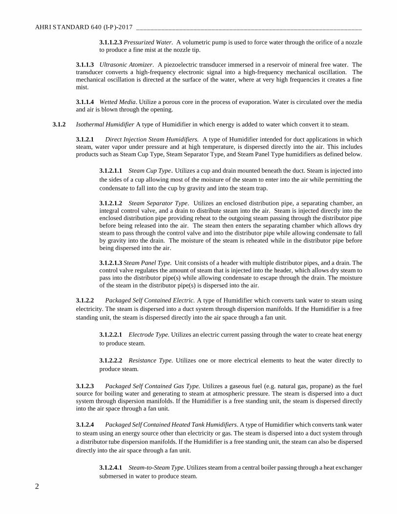
3.1.1.2.3 Pressurized Water. A volumetric pump is used to force water through the orifice of a nozzle
to produce a fine mist at the nozzle tip.
3.1.1.3 Ultrasonic Atomizer. A piezoelectric transducer immersed in a reservoir of mineral free water. The
transducer converts a high-frequency electronic signal into a high-frequency mechanical oscillation. The
mechanical oscillation is directed at the surface of the water, where at very high frequencies it creates a fine
mist.
3.1.1.4 Wetted Media. Utilize a porous core in the process of evaporation. Water is circulated over the media
and air is blown through the opening.
3.1.2 Isothermal Humidifier A type of Humidifier in which energy is added to water which convert it to steam.
3.1.2.1 Direct Injection Steam Humidifiers. A type of Humidifier intended for duct applications in which
steam, water vapor under pressure and at high temperature, is dispersed directly into the air. This includes
products such as Steam Cup Type, Steam Separator Type, and Steam Panel Type humidifiers as defined below.
3.1.2.1.1 Steam Cup Type. Utilizes a cup and drain mounted beneath the duct. Steam is injected into
the sides of a cup allowing most of the moisture of the steam to enter into the air while permitting the
condensate to fall into the cup by gravity and into the steam trap.
3.1.2.1.2 Steam Separator Type. Utilizes an enclosed distribution pipe, a separating chamber, an
integral control valve, and a drain to distribute steam into the air. Steam is injected directly into the
enclosed distribution pipe providing reheat to the outgoing steam passing through the distributor pipe
before being released into the air. The steam then enters the separating chamber which allows dry
steam to pass through the control valve and into the distributor pipe while allowing condensate to fall
by gravity into the drain. The moisture of the steam is reheated while in the distributor pipe before
being dispersed into the air.
3.1.2.1.3 Steam Panel Type. Unit consists of a header with multiple distributor pipes, and a drain. The
control valve regulates the amount of steam that is injected into the header, which allows dry steam to
pass into the distributor pipe(s) while allowing condensate to escape through the drain. The moisture
of the steam in the distributor pipe(s) is dispersed into the air.
3.1.2.2 Packaged Self Contained Electric. A type of Humidifier which converts tank water to steam using
electricity. The steam is dispersed into a duct system through dispersion manifolds. If the Humidifier is a free
standing unit, the steam is dispersed directly into the air space through a fan unit.
3.1.2.2.1 Electrode Type. Utilizes an electric current passing through the water to create heat energy
to produce steam.
3.1.2.2.2 Resistance Type. Utilizes one or more electrical elements to heat the water directly to
produce steam.
3.1.2.3 Packaged Self Contained Gas Type. Utilizes a gaseous fuel (e.g. natural gas, propane) as the fuel
source for boiling water and generating to steam at atmospheric pressure. The steam is dispersed into a duct
system through dispersion manifolds. If the Humidifier is a free standing unit, the steam is dispersed directly
into the air space through a fan unit.
3.1.2.4 Packaged Self Contained Heated Tank Humidifiers. A type of Humidifier which converts tank water
to steam using an energy source other than electricity or gas. The steam is dispersed into a duct system through
a distributor tube dispersion manifolds. If the Humidifier is a free standing unit, the steam can also be dispersed
directly into the air space through a fan unit.
3.1.2.4.1 Steam-to-Steam Type. Utilizes steam from a central boiler passing through a heat exchanger
submersed in water to produce steam.
_______________________________________________________________ AHRI STANDARD 640 (I-P)-2017
3
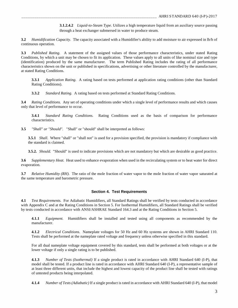
3.1.2.4.2 Liquid-to-Steam Type. Utilizes a high temperature liquid from an auxiliary source passing
through a heat exchanger submersed in water to produce steam.
3.2 Humidification Capacity. The capacity associated with a Humidifier's ability to add moisture to air expressed in lb/h of
continuous operation.
3.3 Published Rating. A statement of the assigned values of those performance characteristics, under stated Rating
Conditions, by which a unit may be chosen to fit its application. These values apply to all units of like nominal size and type
(identification) produced by the same manufacturer. The term Published Rating includes the rating of all performance
characteristics shown on the unit or published in specifications, advertising or other literature controlled by the manufacturer,
at stated Rating Conditions.
3.3.1 Application Rating. A rating based on tests performed at application rating conditions (other than Standard
Rating Conditions).
3.3.2 Standard Rating. A rating based on tests performed at Standard Rating Conditions.
3.4 Rating Conditions. Any set of operating conditions under which a single level of performance results and which causes
only that level of performance to occur.
3.4.1 Standard Rating Conditions. Rating Conditions used as the basis of comparison for performance
characteristics.
3.5 "Shall" or "Should". "Shall" or "should" shall be interpreted as follows:
3.5.1 Shall. Where "shall" or "shall not" is used for a provision specified, the provision is mandatory if compliance with
the standard is claimed.
3.5.2. Should. "Should" is used to indicate provisions which are not mandatory but which are desirable as good practice.
3.6 Supplementary Heat. Heat used to enhance evaporation when used in the recirculating system or to heat water for direct
evaporation.
3.7 Relative Humidity (RH). The ratio of the mole fraction of water vapor to the mole fraction of water vapor saturated at
the same temperature and barometric pressure.
Section 4. Test Requirements
4.1 Test Requirements. For Adiabatic Humidifiers, all Standard Ratings shall be verified by tests conducted in accordance
with Appendix C and at the Rating Conditions in Section 5. For Isothermal Humidifiers, all Standard Ratings shall be verified
by tests conducted in accordance with ANSI/ASHRAE Standard 164.3 and at the Rating Conditions in Section 5.
4.1.1 Equipment. Humidifiers shall be installed and tested using all components as recommended by the
manufacturer.
4.1.2 Electrical Conditions. Nameplate voltages for 50 Hz and 60 Hz systems are shown in AHRI Standard 110.
Tests shall be performed at the nameplate rated voltage and frequency unless otherwise specified in this standard.
For all dual nameplate voltage equipment covered by this standard, tests shall be performed at both voltages or at the
lower voltage if only a single rating is to be published.
4.1.3 Number of Tests (Isothermal) If a single product is rated in accordance with AHRI Standard 640 (I-P), that
model shall be tested. If a product line is rated in accordance with AHRI Standard 640 (I-P), a representative sample of
at least three different units, that include the highest and lowest capacity of the product line shall be tested with ratings
of untested products being interpolated.
4.1.4 Number of Tests (Adiabatic) If a single product is rated in accordance with AHRI Standard 640 (I-P), that model
AHRI STANDARD 640 (I-P)-2017 _______________________________________________________________
4
shall be tested. If a product line is rated in accordance with AHRI Standard 640 (I-P), at least three different units, that
represent the entire capacity range of the product line shall be tested with ratings of untested products being interpolated
or extrapolated.
Section 5. Rating Requirements
5.1 Publication of Ratings. Wherever Application Ratings are published or printed, they shall include or be accompanied by
the Standard Rating, clearly designated as such, including a statement of the conditions at which the ratings apply.
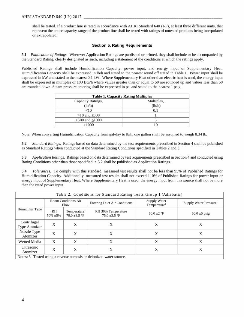
Published Ratings shall include Humidification Capacity, power input, and energy input of Supplementary Heat.
Humidification Capacity shall be expressed in lb/h and stated to the nearest round off stated in Table 1. Power input shall be
expressed in kW and stated to the nearest 0.1 kW. Where Supplementary Heat other than electric heat is used, the energy input
shall be expressed in multiples of 100 Btu/h where values greater than or equal to 50 are rounded up and values less than 50
are rounded down. Steam pressure entering shall be expressed in psi and stated to the nearest 1 psig.
Table 1. Capacity Rating Multiples
Capacity Ratings,
(lb/h)
Multiples,
(lb/h)
≤10 0.1
>10 and ≤300 1
>300 and ≤1000 5
>1000 10
Note: When converting Humidification Capacity from gal/day to lb/h, one gallon shall be assumed to weigh 8.34 lb.
5.2 Standard Ratings. Ratings based on data determined by the test requirements prescribed in Section 4 shall be published
as Standard Ratings when conducted at the Standard Rating Conditions specified in Tables 2 and 3.
5.3 Application Ratings. Ratings based on data determined by test requirements prescribed in Section 4 and conducted using
Rating Conditions other than those specified in 5.2 shall be published as Application Ratings.
5.4 Tolerances. To comply with this standard, measured test results shall not be less than 95% of Published Ratings for
Humidification Capacity. Additionally, measured test results shall not exceed 110% of Published Ratings for power input or
energy input of Supplementary Heat. Where Supplementary Heat is used, the energy input from this source shall not be more
than the rated power input.
Table 2. Conditions for Standard Rating Tests Group 1 (Adiabatic)
Humidifier Type
Room Conditions Air
Flow Entering Duct Air Conditions
Supply Water
Temperature1 Supply Water Pressure1
RH
50% ±5%
Temperature
70.0 ±3.5 °F
RH 30% Temperature
75.0 ±3.5 °F 60.0 ±2 °F 60.0 ±5 psig
Centrifugal
Type Atomizer X X X X X
Nozzle Type
Atomizer X X X X X
Wetted Media X X X X X
Ultrasonic
Atomizer X X X X X
Notes: 1. Tested using a reverse osmosis or deionized water source.
_______________________________________________________________ AHRI STANDARD 640 (I-P)-2017
5
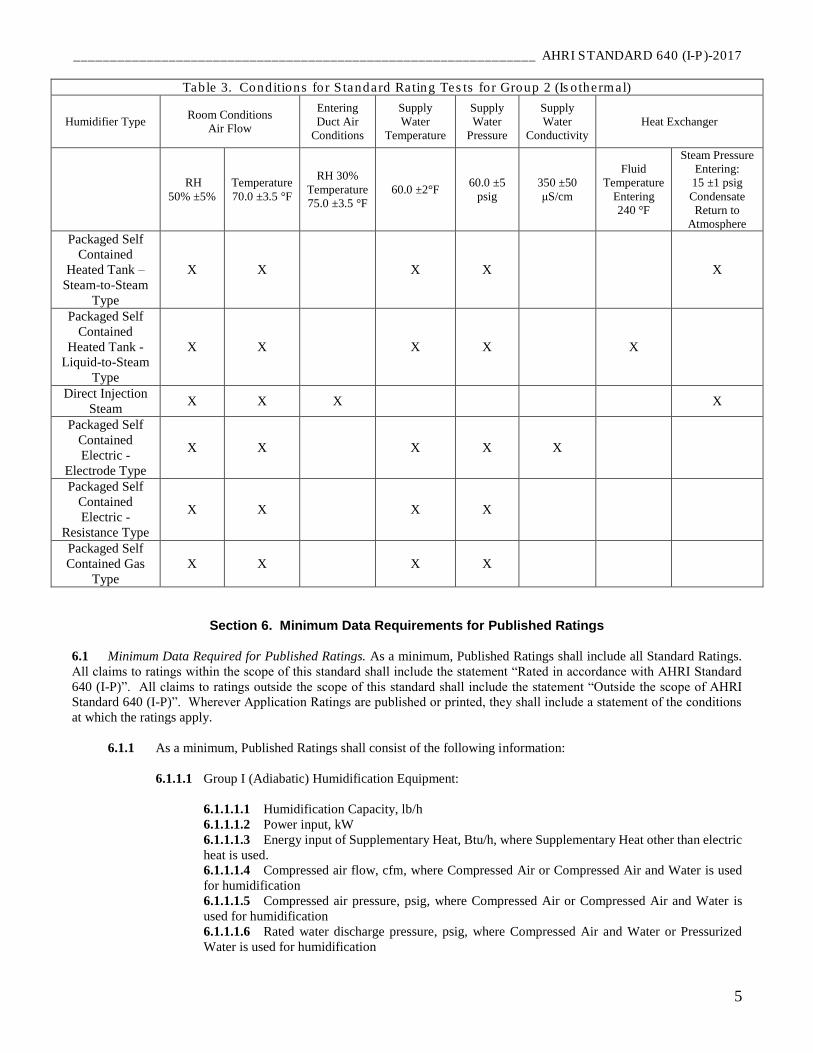
Table 3. Conditions for Standard Rating Tests for Group 2 (Isothermal)
Humidifier Type Room Conditions
Air Flow
Entering
Duct Air
Conditions
Supply
Water
Temperature
Supply
Water
Pressure
Supply
Water
Conductivity
Heat Exchanger
RH
50% ±5%
Temperature
70.0 ±3.5 °F
RH 30%
Temperature
75.0 ±3.5 °F
60.0 ±2°F 60.0 ±5
psig
350 ±50
μS/cm
Fluid
Temperature
Entering
240 °F
Steam Pressure
Entering:
15 ±1 psig
Condensate
Return to
Atmosphere
Packaged Self
Contained
Heated Tank –
Steam-to-Steam
Type
X X X X X
Packaged Self
Contained
Heated Tank -
Liquid-to-Steam
Type
X X X X X
Direct Injection
Steam X X X X
Packaged Self
Contained
Electric -
Electrode Type
X X X X X
Packaged Self
Contained
Electric -
Resistance Type
X X X X
Packaged Self
Contained Gas
Type
X X X X
Section 6. Minimum Data Requirements for Published Ratings
6.1 Minimum Data Required for Published Ratings. As a minimum, Published Ratings shall include all Standard Ratings.
All claims to ratings within the scope of this standard shall include the statement “Rated in accordance with AHRI Standard
640 (I-P)”. All claims to ratings outside the scope of this standard shall include the statement “Outside the scope of AHRI
Standard 640 (I-P)”. Wherever Application Ratings are published or printed, they shall include a statement of the conditions
at which the ratings apply.
6.1.1 As a minimum, Published Ratings shall consist of the following information:
6.1.1.1 Group I (Adiabatic) Humidification Equipment:
6.1.1.1.1 Humidification Capacity, lb/h
6.1.1.1.2 Power input, kW
6.1.1.1.3 Energy input of Supplementary Heat, Btu/h, where Supplementary Heat other than electric
heat is used.
6.1.1.1.4 Compressed air flow, cfm, where Compressed Air or Compressed Air and Water is used
for humidification
6.1.1.1.5 Compressed air pressure, psig, where Compressed Air or Compressed Air and Water is
used for humidification
6.1.1.1.6 Rated water discharge pressure, psig, where Compressed Air and Water or Pressurized
Water is used for humidification
AHRI STANDARD 640 (I-P)-2017 _______________________________________________________________
6
6.1.1.2 Group II (Isothermal) Humidification Equipment:
6.1.1.2.1 Humidification Capacity, lb/h
6.1.1.2.2 Power input, W
6.1.1.2.3 Energy input of Supplementary Heat, Btu/h, where Supplementary Heat other than electric
heat is used.
6.1.1.2.4 Steam pressure, psig, (input steam pressure for direct steam to steam units)
Section 7. Marking and Nameplate Data
7.1 Marking and Nameplate Data. As a minimum, the nameplate shall display:
7.1.1 Manufacturer's name
7.1.2 Model designation
7.1.3 Voltage, phase, amperage, and frequency, if applicable
7.1.4 Compressed air flow and/or pressure ratings, if applicable
7.1.5 Rated water discharge pressure, if applicable
7.1.6 Gas and steam supply pressure, if applicable
7.2 Nameplate Voltage. Where applicable, nameplate voltages for 50 and 60 Hz systems shall include one or more of the
equipment nameplate voltage ratings shown in AHRI Standard 110.
Section 8. Conformance Conditions
8.1 Conformance. While conformance with this standard is voluntary, conformance shall not be claimed or implied for
products or equipment within the standard’s Purpose (Section 1) or Scope (Section 2) unless such claims meet all of the
requirements of the standard and all of the testing and rating requirements are measured and reported in complete compliance
with the standard. Any product that has not met all the requirements of the standard shall not reference, state, or acknowledge
the standard in any written, oral, or electronic communication.
_______________________________________________________________ AHRI STANDARD 640 (I-P)-2017
7
APPENDIX A. REFERENCES - NORMATIVE
A1 Listed here are all standards, handbooks and other publications essential to the formation and implementation of the
standard. All references in this appendix are considered as part of the standard.
A1.1 AHRI Standard 110-2016, Air-Conditioning, Heating and Refrigerating Equipment Nameplate Voltages, 2016,
Air-Conditioning Heating and Refrigeration Institute, 2111 Wilson Blvd., Suite 500, Arlington, VA 22201, U.S.A.
A1.2 ANSI/AHAM HU-1-2016, Portable Household Humidifiers, 2016, Association of Home Appliance
Manufacturers, 1111 19th St., N.W., Suite 402, Washington, DC 20036, U.S.A.
A1.3 ANSI/AHRI Standard 610 (I-P)-2014, Performance Rating of Central System Humidifiers, 2014, Air-
Conditioning Heating and Refrigeration Institute, 2111 Wilson Blvd., Suite 500, Arlington, VA 22201, U.S.A.
A1.4 ANSI/AHRI Standard 620 (I-P)-2014, Performance Ratings of Self-Contained Humidifiers for Residential
Application, 2014, Air-Conditioning Heating and Refrigeration Institute, 2111 Wilson Blvd., Suite 500, Arlington, VA
22201, U.S.A.
A1.5 ANSI/ASHRAE Standard 41.1-2013, Standard Method for Temperature Measurement, 2013, American
Society of Heating, Refrigerating and Air-Conditioning Engineers, Inc., 1791 Tullie Circle N.E., Atlanta, GA 30329,
U.S.A.
A1.6 ANSI/ASHRAE Standard 41.2-1987 (RA 92), Standard Methods for Laboratory Airflow Measurement, 1992,
American Society of Heating, Refrigerating and Air-Conditioning Engineers, Inc., 1791 Tullie Circle N.E., Atlanta, GA
30329, U.S.A.
A1.7 ANSI/ASHRAE Standard 41.3-2014, Standard Method for Pressure Measurement, 2014, American Society of
Heating, Refrigerating and Air-Conditioning Engineers, Inc., 1791 Tullie Circle N.E., Atlanta, GA 30329, U.S.A.
A1.8 ASHRAE Standard 164.3 – 2015, Method of Test for Commercial and Industrial Isothermal Humidifiers, 2015, American Society of Heating, Refrigerating and Air-Conditioning Engineers, Inc., 1791 Tullie Circle N.E., Atlanta, GA
30329, U.S.A.
A1.9 ASHRAE Terminology, https://www.ashrae.org/resources--publications/free-resources/ashraeterminology,
2016, American Society of Heating, Refrigerating and Air-Conditioning Engineers, Inc., 1791 Tullie Circle, N.E.,
Atlanta, GA 30329, U.S.A.
APPENDIX B. REFERENCES - INFORMATIVE
None.
AHRI STANDARD 640 (I-P)-2017 _______________________________________________________________
8
APPENDIX C. METHOD OF TEST FOR ADIABATIC COMMERCIAL AND INDUSTRIAL HUMIDIFIERS -
NORMATIVE
C1 Purpose. The purpose of this appendix is to specify for Commercial and Industrial Adiabatic Humidifiers:
instrumentation; measurement and treatment apparatus; and test procedures for determining their capacity and related
performance.
C2 Scope. This appendix applies to Adiabatic Humidifiers as defined in Section 3 of this standard. This appendix applies
to laboratory testing for purposes of evaluating Humidification Capacity, power input, and energy input of Supplementary Heat
within its scope. This appendix is not applicable to tests conducted in the field or on the production line.
C3 Test Measurements and Instrumentation. Except as noted below, instrumentation shall be in accordance with the
specified test requirements as outlined in 4.1
C3.1 Airflow Rate Measuring Instruments. Airflow rate measuring instruments involved in the measurement of
airflow shall be in accordance with Section 6 of ANSI/ASHRAE Standard 41.2.
C3.1.1 Nozzle Construction. Construction of nozzles shall be in accordance with Figure 6 of ANSI/ASHRAE
Standard 41.2. Nozzles shall be sized for a throat velocity not less than 3,000 ft/min nor more than 7,000 ft/min.
When nozzles are constructed in accordance with ANSI/ASHRAE Standard 41.2 and installed in accordance
with C4.1.1, they may be used without calibration.
C3.2 Air Pressure Measuring Instruments. Pressure taps and measurement techniques shall be in accordance with
ANSI/ASHRAE Standard 41.3.
C3.3 Temperature Measuring Instruments. Both wet- and dry-bulb air temperatures shall be measured in accordance
with ANSI/ASHRAE Standard 41.1. A measurement accuracy of ±0.5 °F or better shall be obtained. The smallest scale
division of the instrument shall be no greater than 0.1 °F.
C3.4 Water Quantity Measuring Instruments. Water quantity measurements shall be made with one of the following
instruments having an accuracy as shown:
C3.4.1 Scale and tank. Weight measurements shall be made by collecting water in a tank and placing it on a
scale with an accuracy of at least ± 1.0% of the total range of the scale, lb/h.
C3.4.2 Calibrated pressurized cylinder. Weight measurements shall be made by collecting water in a
calibrated cylinder and pressure gauge by placing it on a scale with an accuracy of at least ± 1.0% of the total
range of the scale, lb/h.
C3.5 Water Pressure Measuring Instruments. Water pressure shall be measured with oil-filled gauges, electronic
transducers, or other instruments that provide a maximum error of ±1% of the maximum observed reading or ±0.5 psi,
whichever is larger. Since the pressures measured in this standard are not expected to be steady, the pressure reading
indicated on any instrument will fluctuate with time. In order to obtain a true reading, either the instrument shall be
damped or the readings shall be averaged in a suitable manner. Multipoint or continuous record averaging can be
accomplished with instruments and analyzers designed for this purpose.
C3.6 Electrical Voltage. Voltage shall be measured using a volt meter connected to the humidifier over the duration
of the test. Volt meters shall have an accuracy of ±1.0% of the observed reading.
C3.7 Power Measurement. Power shall be measured using a wattmeter connected to the humidifier over the duration
of the test. Watt meters shall have an accuracy of ±1.0% of the observed reading.
C3.8 Electrical Energy Measurement. Energy shall be measured using a watt-hour meter connected to the humidifier
over the duration of the test. Watt-hour meters shall have an accuracy of ±1.0% of the observed reading.
_______________________________________________________________ AHRI STANDARD 640 (I-P)-2017
9
C3.9 Time Measurements. A timepiece that displays time in seconds and keeps time accurate to within ±2 minutes
per day shall be used for all time measurements. Calibration is not necessary.
C3.10 Other Measurements.
C3.10.1 Supplementary Heat (Water) Flow Rate Measurements. Flow rate measurements shall be made with
a liquid type flow meter having an accuracy of ± 2.0% of the quantity measured.
C3.10.2 Supplementary Heat (Steam) Condensate Quantity Measurements. Condensate quantity shall be
measured with a liquid quantity meter measuring either weight or volume having an accuracy of ± 2.0% of the
quantity measured.
C4 Measuring and Treatment Apparatus.
C4.1 Method 1 (Testing in duct)
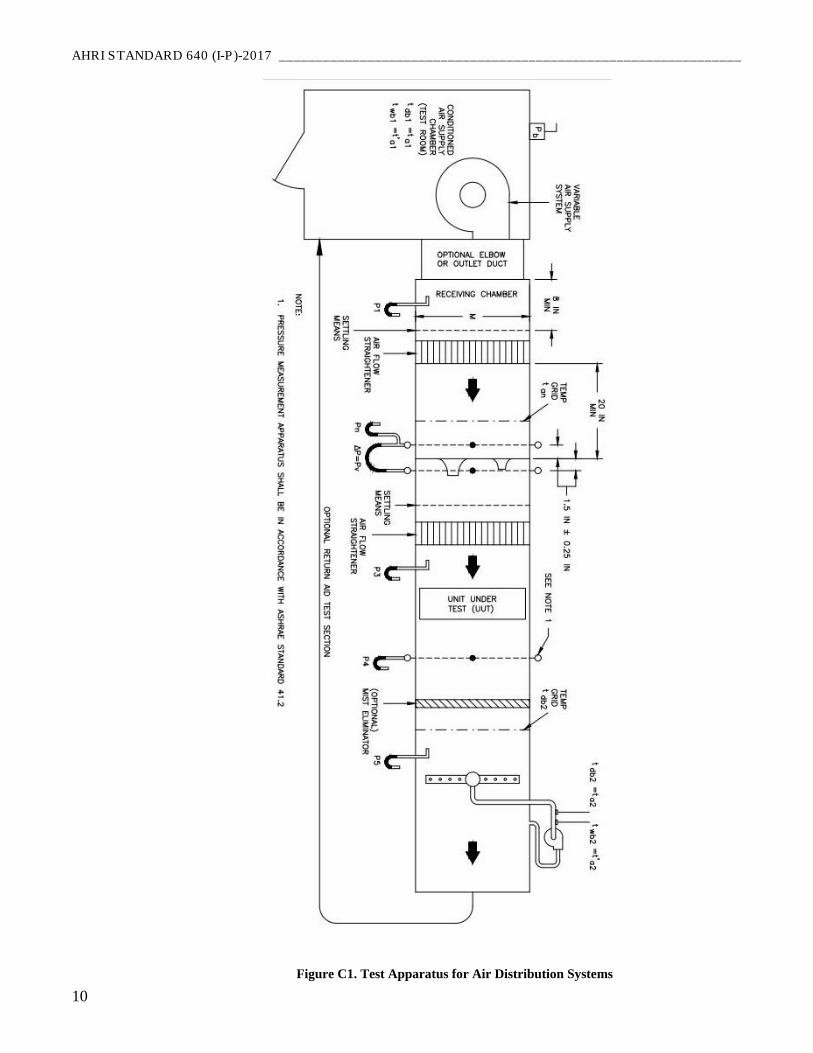
C4.1.1 Airflow Rate Measuring Apparatus for Air Distribution Systems. Accurate and precise measurement
of airflow rate is necessary to the testing of Humidifiers, which receive air from the space in which they are
located and deliver it to an air distribution system. The Humidifier itself exerts no control over the airflow rate
circulated through the duct system, yet the performance of several types of furnace and duct-mounted
Humidifiers is substantially affected by air velocity within the system. Airflow rates shall be measured using
the apparatus described below and in Figure C1. The apparatus shall be constructed as described either in this
appendix or in those publications referenced in this standard.
The apparatus consists of a fan to serve as supply with variable-speed or damper to control flow rate. It includes
a receiving chamber with settling means, one or more airflow measuring nozzles installed in a nozzle plate, a
discharge chamber with settling means, and suitable transformation pieces for connecting the airflow rate
measuring apparatus to other sections of the air distribution system. The apparatus shall be constructed in
accordance with Section 5.3 of ANSI/ASHRAE Standard 41.2, for free inlet, ducted outlet test chamber as
diagramed in Figure 13, Inlet Chamber Setup for Multiple Nozzles in Chamber.
C4.1.1.1 Setup. The requirements of the airflow rate measuring apparatus, setup for testing, proper connections
and connecting ductwork, design and application of appurtenances such as straighteners, mixers,
settling means, sampling devices, and variable supply or exhaust means, shall be in accordance with
Section 7.2 of ANSI/ASHRAE Standard 41.2 for inlet test chamber.
C4.1.2 Air Treatment Apparatus. Each test facility shall be provided with the air treatment apparatus to
maintain prescribed conditions of temperature, humidity, duct airflow velocity, and pressure of the air entering
the test section in accordance with Section 8.2 of ANSI/ASHRAE Standard 41.2.
C4.1.3 Humidifier Test Sections. Humidifier test sections shall be provided to mount the various classes of
Humidifiers. The test sections shall be constructed as described below.
C4.1.3.1 Return Air (Duct or Plenum) Test Sections. Each return air (duct or plenum) test section
shall contain a diffusion baffle and airflow straightener to assure uniform air velocity and temperature
within the test section. If two or more humidifier test sections are located in series, the transition and
turning fittings connecting them shall be designed to minimize disturbances in the air stream. Similar
transition and turning fittings shall be used to connect a humidifier test section to an airflow rate
measuring apparatus, heating unit, or other apparatus.
C4.1.4 Plenum and Duct Sections. Plenum and duct sections shall be used to connect the airflow rate
measuring apparatus with other sections of the test apparatus and shall be insulated to prevent heat leakage.
All joints and seams in the connecting ducts and between the connecting ducts and adjoining sections of the
test apparatus shall be sealed, using tape or other sealants, so that the test apparatus leakage rate must not exceed
20 cfm when a negative pressure of 1.0 in H2O is maintained at the plenum's inlet. Special attention shall be
paid to sealing the heating unit of the heating section to prevent air leakage.
AHRI STANDARD 640 (I-P)-2017 _______________________________________________________________
10
Figure C1. Test Apparatus for Air Distribution Systems
_______________________________________________________________ AHRI STANDARD 640 (I-P)-2017
11
C4.1.5 Water Quantity Measuring Apparatus. Means shall be provided to measure the quantity of supply
water entering and liquid water exiting the Humidifier under test in accordance with C3.4.
C4.1.6 Temperature Measuring Apparatus. Air temperature measurements in ducts and fluid temperature
measurements within conduits shall be made in accordance with C3.3.
C4.1.7 Supplemental Heat Measuring Apparatus. Means shall be provided to measure the amount of energy
added from water, steam, electricity, or any other energy source used to supply Supplementary Heat to a
Humidifier with a recirculating coil in accordance with C3.10.1, C3.10.2.
C4.2 Method 2 (Room test)
C4.2.1 Humidifier Test Room. The test facility shall be provided with air treating equipment to maintain
the prescribed conditions of temperature, humidity, and pressure within the test area. Unit under test shall
operate at 100% capacity for Standard Rating Conditions as indicated in Table 2.
C4.2.2 Water Quantity Measuring Apparatus. Means shall be provided to measure the quantity of supply
and waste water used by the Humidifier under test in accordance with C3.4.
C4.2.3 Makeup Air/Exhaust Air Conditions. Sufficient makeup air shall be provided and exhaust air shall
be removed to maintain the room conditions as specified in Table 2. The intent is to ensure a consistent entering
condition for the humidifier.
C5 Test Procedures.
C5.1 Test Methods. The test methods described in this appendix shall be used in determining the Humidification
Capacity.
C5.1.1 Applicability of Test Methods. Humidifiers shall be tested using the method described in this appendix
which coincides with the installation method or installation location described in the manufacturer’s installation
instructions.
C5.2 Conditions of Test. The following conditions shall be maintained throughout the tests:
C5.2.1 Air Pressure in the Air Treatment Apparatus. The air pressure around the unit under test (P3 and P4 in
Figure C1) shall be maintained as stated, except that a test tolerance of ± 0.070 in Hg. shall be allowed.
C5.2.2 Air Temperatures. The air entering the humidifier test section shall be maintained at the dry-bulb
temperature and relative humidity selected. During any test, the variation of dry-bulb temperatures shall not be
more than 3.5F and the variation of relative humidity shall be not more than 5%. The average of these temperatures
shall be the test temperature. This average test temperature shall be within 2.0F of the selected dry-bulb
temperature and within 5% of the selected relative humidity. (See C5.3.5.2 for temperature correction procedure.)
C5.2.3 Duct Airflow Velocity. The duct airflow velocity in the vicinity of the unit under test shall be 500 fpm
± 2% with the Humidifier installed, using the calculation method listed in C5.3.5.1.
C5.2.4 Electrical Supply Source. Humidifiers that require electrical energy for proper operation shall be
connected to a supply of the nameplate voltage and frequency, as measured at the electrical terminals of the
humidifier. A volt meter shall be installed in the electrical circuit when a humidifier is connected to an electrical
supply circuit. Tolerances on voltage shall be ± 1% throughout the test.
C5.2.5 Units with Supplementary Heat (Water). The pressure of the feed water entering the recirculating coil
shall be maintained with a test tolerance of ± 1.0 psi. The temperature of the feed water entering the recirculating
coil shall be maintained and a test tolerance of ± 2.0 F shall be allowed.
C5.2.6 Water Supply Source. The water supply source shall be directly connected to the Humidifier, and the
water control valve on the Humidifier shall regulate the water flow rate. The pressure of the water entering the
water control valve shall be maintained and a test tolerance of ± 3.0 psi shall be allowed. The temperature of the
water entering the water control valve shall be maintained and a test tolerance of ± 2.0 F shall be allowed.
AHRI STANDARD 640 (I-P)-2017 _______________________________________________________________
12
C5.3 Test Method. This test method is used to determine the Humidification Capacity of a Humidifier which is installed
in the return air duct system or the return air plenum system of an air distribution system. In either case, the Humidifier
shall be installed in the humidifier test section in accordance with manufacturer's written instructions.
C5.3.1 Test Apparatus. The test apparatus is composed of the following components where applicable:
C5.3.1.1 Airflow rate measuring apparatus for air distribution systems (C4.1.1)
C5.3.1.2 Air treatment apparatus (C4.1.2)
C5.3.1.3 Temperature measuring apparatus (C4.1.6)
C5.3.1.4 Water quantity measuring apparatus (C4.1.5 or 4.2.2)
C5.3.1.5 Supplemental heat measuring apparatus (C4.1.7)
C5.3.1.6 Humidifier test sections (C4.1.3)
C5.3.1.7 Plenum and duct sections (C4.1.4)
C5.3.1.8 Humidifier test room (C4.2.1)
C5.3.2 Air Velocity. The air velocity in the return air duct system or the return air plenum system shall be
maintained at 500 fpm or as recommended by the manufacturer based on 75.0°F dry-bulb temperature and
56.5°F wet-bulb temperature as measured at the air measuring device section throughout the test. (A test
tolerance of ± 20 fpm shall be allowed.) The air flow shall be straightened as per Figure C1. No diverters,
plates, or air directing devices, other than those supplied with the Humidifier by the manufacturer, shall be used
to direct air at a higher-than-average velocity either toward or away from the Humidifier under test.
C5.3.2.1 The cross-sectional area shall be the cross-sectional area of the humidifier test section
measured 12.0 in upstream of the test unit and perpendicular to the direction of airflow.
C5.3.3 Performance Test. The Humidifier to be tested shall be installed in the humidifier test room as
described in C4 and the air temperatures, water temperatures, water pressures for the test shall be maintained
as described in C5.1.
C5.3.3.1 Water Supply Source Adjustment. If the water measuring apparatus prescribed in C4.1.5
and C4.2.2 does not permit supply and waste water flow rate determination while the Humidifier is
connected to the water supply source, the procedure described below shall be followed. The purpose
for adjusting the water flow rate is to establish the water level that is to be maintained in a humidifier
which has a float or balanced-pan valve, or the water flow rate for a humidifier equipped with an
electric water control valve (solenoid valve).
C5.3.3.1.1 Water Level Determination. A Humidifier which contains a reservoir shall be
installed in the test section and adjusted in accordance with the manufacturer's
recommendations. It shall be operated in the humidifier test section while connected to the
water supply source described in C5.2.6. The water level in the reservoir shall be observed.
After it has remained constant during an operating period of not less than 30 minutes, a water
level line shall be marked on the reservoir. This reservoir water level shall be maintained
during the capacity test.
C5.3.3.1.2 Water Flow Rate Determination. A Humidifier which utilizes an electric water
control valve shall be adjusted in accordance with the manufacturer's recommendations. (An
alternative procedure is to remove the water control valve from the Humidifier and to adjust
the flow rate in accordance with the manufacturer's recommendations.) The water control
valve shall be opened electrically, and the water flow rate through the valve shall be
determined using C4.1.5 and C4.2.2. The period of the preliminary test shall not be less than
60 minutes.
C5.3.3.2 Connection for Capacity Test. The Humidifier under test shall be connected to the water
quantity measuring apparatus described in C4.1.5 and C4.2.2.
C5.3.3.2.1 Humidifiers having a float or balanced pan valve shall be adjusted to maintain the
water level determined in C5.3.3.1.1.
_______________________________________________________________ AHRI STANDARD 640 (I-P)-2017
13
C5.3.3.2.2 Humidifiers having an electric water control valve shall be adjusted or the
water-control supply source shall be controlled so that it equals the water flow rate
determined in C5.3.3.1.2.
C5.3.3.3 Data to Be Recorded. All data required to determine the Humidification Capacity of the
unit shall be observed and recorded where applicable.
C5.3.3.3.1 Air Pressures. Air pressures or a differential pressure shall be observed and
recorded at the following locations:
C5.3.3.3.1.1 Static pressure drop across flow nozzle, (pv), in H2O
C5.3.3.3.1.2 Absolute pressure of air entering flow nozzle, (Pn), in Hg
C5.3.3.3.1.3 Pressure in return air duct or return air plenum humidifier test section
below atmospheric pressure, in H2O
C5.3.3.3.2 Air Temperatures. Dry-bulb and wet-bulb temperatures entering the Humidifier,
F.
C5.3.3.3.2.1 Air entering flow nozzles
C5.3.3.3.2.2 Air entering return air duct or return air plenum
C5.3.3.3.2.3 Air entering supply air plenum or supply air duct
C5.3.3.3.3 Airflow Rate. Airflow rate measurement data shall be recorded in accordance
with Section 9 of ANSI/ASHRAE 41.2.
C5.3.3.3.4 Electric Power Input. Power input (including transformer) shall be recorded in
W. Electric energy input shall be calculated from this data and expressed in Btu/h.
C5.3.3.3.5 Time. The time of each reading and the elapsed time between successive readings
of all data, seconds.
C5.3.3.3.6 Water Temperatures and Water Pressures.
C5.3.3.3.6.1 Water temperature entering and leaving the Humidifier, F
C5.3.3.3.6.2 Water pressure during test or during preliminary water adjustment, psig
C5.3.3.3.7 Water Quantity. Weights or water flow rates
C5.3.3.3.7.1 Supply water to Humidifier, lb or gal
C5.3.3.3.7.2 Drain water, lb or gal
C5.3.3.3.7.3 Unevaporated water (where used), lb/h or gal/h (mist collection)
C5.3.3.3.8 Supplementary Heat.
C5.3.3.3.8.1 The type of supplementary heat (if applicable)
C5.3.3.3.8.2 The energy input from supplementary heat shall be recorded in Btu/h
C5.3.3.4 Procedure. After prescribed Rating Conditions for the test have been attained, no less than
five sets of readings shall be taken. The duration of the test shall not be less than thirty minutes. The
test shall be continued until the weight or volume of water evaporated or injected into the Humidifier
is within 5% for four successive test readings.
C5.3.4 Test Results. The Humidification Capacity of the Humidifier under test shall be determined using
C5.3.5.2 and shall be the average Humidification Capacity of four successive test runs complying with this
section.
C5.3.5 Capacity Rating Calculations.
AHRI STANDARD 640 (I-P)-2017 _______________________________________________________________
14
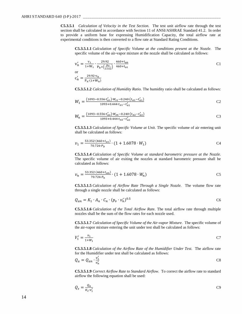
C5.3.5.1 Calculation of Velocity in the Test Section. The test unit airflow rate through the test
section shall be calculated in accordance with Section 11 of ANSI/ASHRAE Standard 41.2. In order
to provide a uniform base for expressing Humidification Capacity, the total airflow rate at
experimental conditions is then converted to a flow rate at Standard Rating Conditions.
C5.3.5.1.1 Calculation of Specific Volume at the conditions present at the Nozzle. The
specific volume of the air-vapor mixture at the nozzle shall be calculated as follows:
vn′ =
v1
1+W1∙
29.92
Pb+(pv
13.62)
∙460+tan
460+ta1 C1
or
cn′ =
29.92∙vn
Pn∙(1+Wn)
C5.3.5.1.2 Calculation of Humidity Ratio. The humidity ratio shall be calculated as follows:
𝑊1 =(1093−0.556∙𝑡𝑎1
′ )∙𝑊𝑠1−0.240∙(𝑡𝑎1−𝑡𝑎1′ )
1093+0.444∙𝑡𝑎1−𝑡𝑎1′ C2
𝑊𝑛 =(1093−0.556∙𝑡𝑎2
′ )∙𝑊𝑠𝑛−0.240∙(𝑡𝑎2−𝑡𝑎2′ )
1093+0.444∙𝑡𝑎2−𝑡𝑎2′ C3
C5.3.5.1.3 Calculation of Specific Volume at Unit. The specific volume of air entering unit
shall be calculated as follows:
𝑣1 =53.352∙(460+𝑡𝑎1)
70.726∙𝑃𝑏∙ (1 + 1.6078 ∙ 𝑊1) C4
C5.3.5.1.4 Calculation of Specific Volume at standard barometric pressure at the Nozzle.
The specific volume of air exiting the nozzles at standard barometric pressure shall be
calculated as follows:
𝑣𝑛 =53.352∙(460+𝑡𝑎𝑛)
70.726∙𝑃𝑛∙ (1 + 1.6078 ∙ 𝑊𝑛) C5
C5.3.5.1.5 Calculation of Airflow Rate Through a Single Nozzle. The volume flow rate
through a single nozzle shall be calculated as follows:
𝑄𝑎𝑛 = 𝐾1 ∙ 𝐴𝑛 ∙ 𝐶𝑛 ∙ (𝑝𝑣 ∙ 𝑣𝑛′ )0.5 C6
C5.3.5.1.6 Calculation of the Total Airflow Rate. The total airflow rate through multiple
nozzles shall be the sum of the flow rates for each nozzle used.
C5.3.5.1.7 Calculation of Specific Volume of the Air-vapor Mixture. The specific volume of
the air-vapor mixture entering the unit under test shall be calculated as follows:
𝑉1′ =
𝑣1
1+𝑊1 C7
C5.3.5.1.8 Calculation of the Airflow Rate of the Humidifier Under Test. The airflow rate
for the Humidifier under test shall be calculated as follows:
𝑄𝑎 = 𝑄𝑎𝑛 ∙𝑣1
′
𝑣𝑛′ C8
C5.3.5.1.9 Correct Airflow Rate to Standard Airflow. To correct the airflow rate to standard
airflow the following equation shall be used:
𝑄𝑠 =𝑄𝑎
𝐾2∙𝑣1′ C9
_______________________________________________________________ AHRI STANDARD 640 (I-P)-2017
15
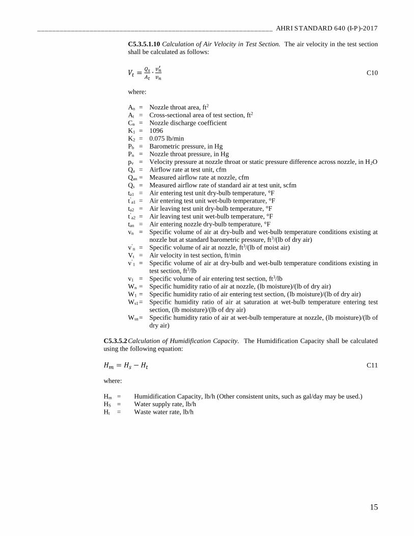
C5.3.5.1.10 Calculation of Air Velocity in Test Section. The air velocity in the test section
shall be calculated as follows:
𝑉𝑡 =𝑄𝑠
𝐴𝑡∙
𝑣𝑛′
𝑣𝑛 C10
where:
An = Nozzle throat area, ft2
At = Cross-sectional area of test section, ft2
Cn = Nozzle discharge coefficient
K1 = 1096
K2 = 0.075 lb/min
Pb = Barometric pressure, in Hg
Pn = Nozzle throat pressure, in Hg
pv = Velocity pressure at nozzle throat or static pressure difference across nozzle, in H2O
Qa = Airflow rate at test unit, cfm
Qan = Measured airflow rate at nozzle, cfm
Qs = Measured airflow rate of standard air at test unit, scfm
ta1 = Air entering test unit dry-bulb temperature, °F
t’a1 = Air entering test unit wet-bulb temperature, °F
ta2 = Air leaving test unit dry-bulb temperature, °F
t’a2 = Air leaving test unit wet-bulb temperature, °F
tan = Air entering nozzle dry-bulb temperature, °F
vn = Specific volume of air at dry-bulb and wet-bulb temperature conditions existing at
nozzle but at standard barometric pressure, ft3/(lb of dry air)
v’n = Specific volume of air at nozzle, ft3/(lb of moist air)
Vt = Air velocity in test section, ft/min
v’1 = Specific volume of air at dry-bulb and wet-bulb temperature conditions existing in
test section, ft3/lb
v1 = Specific volume of air entering test section, ft3/lb
Wn = Specific humidity ratio of air at nozzle, (lb moisture)/(lb of dry air)
W1 = Specific humidity ratio of air entering test section, (lb moisture)/(lb of dry air)
Ws1 = Specific humidity ratio of air at saturation at wet-bulb temperature entering test
section, (lb moisture)/(lb of dry air)
Wsn = Specific humidity ratio of air at wet-bulb temperature at nozzle, (lb moisture)/(lb of
dry air)
C5.3.5.2 Calculation of Humidification Capacity. The Humidification Capacity shall be calculated
using the following equation:
𝐻𝑚 = 𝐻𝑠 − 𝐻𝑡 C11
where:
Hm = Humidification Capacity, lb/h (Other consistent units, such as gal/day may be used.)
HS = Water supply rate, lb/h
Ht = Waste water rate, lb/h