PERFORMANCE OF STEEL PIPELINES BACKFILLED WITH …
143
PERFORMANCE OF STEEL PIPELINES BACKFILLED WITH CONTROLLED LOW-STRENGTH MATERIAL (CLSM) UNDER SEISMIC WAVE PROPAGATION AND REVERSE-SLIP FAULT RUPTURE A DISSERTATION IN Civil Engineering and Geosciences Presented to the Faculty of the University of Missouri-Kansas City in partial fulfillment of the requirements for the degree DOCTOR OF PHILOSOPHY by PRAPON SOMBOONYANON B.E., King’s Mongkhut Institute of Technology of Thonburi, 1999 B.S., University of Missouri-Kansas City, 2001 M.S., University of Missouri-Kansas City, 2003 Kansas City, Missouri 2019
Transcript of PERFORMANCE OF STEEL PIPELINES BACKFILLED WITH …

PERFORMANCE OF STEEL PIPELINES BACKFILLED WITH CONTROLLED
LOW-STRENGTH MATERIAL (CLSM) UNDER SEISMIC WAVE
PROPAGATION AND REVERSE-SLIP FAULT RUPTURE
A DISSERTATION IN
Civil Engineering
and
Geosciences
Presented to the Faculty of the University
of Missouri-Kansas City in partial fulfillment of
the requirements for the degree
DOCTOR OF PHILOSOPHY
by
PRAPON SOMBOONYANON
B.E., King’s Mongkhut Institute of Technology of Thonburi, 1999
B.S., University of Missouri-Kansas City, 2001
M.S., University of Missouri-Kansas City, 2003
Kansas City, Missouri
2019

© 2019
PRAPON SOMBOONYANON
ALL RIGHTS RESERVED

iii
PERFORMANCE OF STEEL PIPELINES BACKFILLED WITH CONTROLLED
LOW-STRENGTH MATERIAL (CLSM) UNDER SEISMIC WAVE
PROPAGATION AND REVERSE-SLIP FAULT RUPTURE
Prapon Somboonyanon, Candidate for the Doctor of Philosophy Degree
University of Missouri-Kansas City, 2019
ABSTRACT
Seismic events may drastically damage buried pipelines affecting economy and
public safety. Traditionally, buried pipelines are bedded and backfilled with compacted
soils, which is labor intensive, time consuming, and could be a safety hazard to workers.
Many studies have shown that achieving a proper compaction level around pipelines can
be a difficult task. Improper compaction can greatly reduce performance of the pipelines
under loads.
Controlled Low-Strength Materials (CLSM) is a group of cementitious materials
that can be used as an alternative to compacted soils to backfill pipelines. These mixtures
are highly flowable in their fresh state and are solid in the final state providing a uniform
support around pipelines. Although there is considerable research about the advantages
of using CLSM to backfill pipelines from construction point of view, there is no research
on the performance of pipelines embedded in CLSM subject to seismic loads. In this
research, 3D FEA was conducted using ABAQUS software to determine the

iv
performance of buried steel pipes backfilled with CLSM when subjected to seismic wave
propagation and reverse-slip fault rupture.
Under seismic wave propagation, the study started by evaluating the ASCE
guidelines and its design limitations. Then, several FE model parameters were evaluated
for their effects on FE model results. After setting the model parameters to match the
predicted stresses by the ASCE guidelines, the developed FE model was used to evaluate
the pipe seismic performance with various soil and CLSM backfill materials. Both linear
and non-linear material behavior were considered in this study.
Under seismic fault rupture, the study developed a 3D FE model matching results
from a full-scale testing performed by others. Various FE model parameters were also
evaluated. Then, the developed FE model was utilized to determine the pipe seismic
performance of CLSM mixture compared to compacted soil backfill.
Results indicated that for 3D FEA pipe seismic analysis, FE model parameters
can have a significant effect on the results. In addition, with a proper design buried steel
pipe embedded in CLSM backfill with all its inherent advantages can perform as well as
or better than soils in seismic prone areas.

v
APPROVAL PAGE
The faculty listed below, appointed by the Dean of the School of Graduate
Studies, have examined a dissertation titled “Performance of Steel Pipelines Backfilled
with Controlled Low-Strength Material (CLSM) under Seismic Wave Propagation and
Reverse-Slip Fault Rupture,” presented by Prapon Somboonyanon, candidate for the
Doctor of Philosophy degree, and certify that in their opinion it is worthy of acceptance.
Supervisory Committee
Ceki Halmen, Ph.D., P.E., Committee Chair
Department of Civil and Mechanical Engineering
Ganesh Thiagarajan, Ph.D., P.E.
Department of Civil and Mechanical Engineering
John T. Kevern, Ph.D., P.E., FACI, LEED AP
Department of Civil and Mechanical Engineering
Jejung Lee, Ph.D.
Department of Geosciences
Tina M. Niemi, Ph.D., R.G.
Department of Geosciences

vi
TABLE OF CONTENTS
ABSTRACT ................................................................................................................... iii
LIST OF ILLUSTRATIONS ......................................................................................... xi
LIST OF TABLES ....................................................................................................... xvi
ACKNOWLEDGEMENTS ....................................................................................... xviii
Chapter
1. INTRODUCTION ...................................................................................................... 1
1.1 General Overview and Background ................................................................ 1
1.1.1 Introduction .......................................................................................... 1
1.1.2 Controlled Low-Strength Material (CLSM) ........................................ 2
1.1.3 Seismic Phenomena .............................................................................. 3
1.1.3.1 Seismic Wave Propagation ..................................................... 4
1.1.3.2 Seismic Fault Rupture ............................................................. 6
1.1.4 Finite Element Modeling ...................................................................... 7
1.2 Research Objective ......................................................................................... 8
1.3 Scope and Rationale........................................................................................ 8
1.4 Research Significance ................................................................................... 10
2. LITERATURE REVIEW ......................................................................................... 11
2.1 CLSM Backfill Applications ........................................................................ 11
2.2 Seismic Performance of Buried Pipelines .................................................... 14
2.2.1 Buried Pipelines Subjected to Seismic Wave Propagation ................ 14
2.2.2 Buried Pipelines Subjected to Seismic Fault Rupture ........................ 18

vii
2.3 Summary ....................................................................................................... 22
3. BURIED PIPELINES SUBJECT TO SEISMIC WAVE PROPAGATION ........... 25
3.1 Introduction ................................................................................................... 25
3.2 Research Methodology with Elastic Materials ............................................. 25
3.2.1 ASCE Guidelines ............................................................................... 26
3.2.2 3D Finite Element Models ................................................................. 28
3.2.3 FE Model Parametric Study ............................................................... 30
3.2.3.1 Soil-Pipe Interaction ............................................................. 31
3.2.3.2 Boundary Condition .............................................................. 32
3.2.3.3 FE Model Width and Depth .................................................. 33
3.2.3.4 FE Model Length .................................................................. 34
3.2.3.5 Friction Coefficients at Interfaces......................................... 35
3.2.3.6 Relationship between Material Young’s Modulus and Soil
Spring Stiffness ..................................................................... 36
3.2.3.7 FE Model Dimension Scale Factor ....................................... 38
3.2.4 Pipe Seismic Performance of Various Backfill Materials .................. 39
3.2.5 Effect from One- and Three-Directional Seismic Wave .................... 40
3.2.6 Pipe End Conditions ........................................................................... 40
3.3 Results and Discussions with Elastic Materials ............................................ 41
3.3.1 ASCE Guidelines ............................................................................... 41
3.3.2 FE Model Parametric Study ............................................................... 42

viii
3.3.2.1 Soil-Pipe Interaction ............................................................. 42
3.3.2.2 Boundary Condition .............................................................. 47
3.3.2.3 FE Model Width ................................................................... 48
3.3.2.4 FE Model Depth.................................................................... 49
3.3.2.5 FE Model Length .................................................................. 50
3.3.2.6 Friction Coefficients at Interfaces......................................... 53
3.3.2.7 Relationship between Material Young’s Modulus and Soil
Spring Stiffness ..................................................................... 54
3.3.2.8 FE Model Dimension Scale Factor ....................................... 62
3.3.3 Pipe Seismic Performance of Various Backfill Materials .................. 64
3.3.4 Effect from One- and Three-Directional Seismic Wave .................... 66
3.3.5 Pipe End Conditions ........................................................................... 69
3.4 Research Methodology with Inelastic Materials .......................................... 70
3.4.1 3D Finite Element Models ................................................................. 70
3.4.2 Inelastic Material Properties ............................................................... 71
3.4.3 FE Model Parametric Study ............................................................... 74
3.5 Results and Discussions with Inelastic Materials ......................................... 76
3.5.1 FE Model Parametric Study ............................................................... 76
3.5.1.1 Soil Spring Stiffness ............................................................. 76
3.5.1.2 Dashpot Element ................................................................... 82

ix
3.5.1.3 Dashpot Element & Soil Spring ........................................... 84
3.5.2 Pipe Seismic Performance of Various Backfill Materials .................. 86
4. BURIED PIPELINES SUBJECT TO REVERSE-SLIP FAULT RUPTURE ......... 89
4.1 Introduction ................................................................................................... 89
4.2 Research Methodology ................................................................................. 89
4.2.1 3D Finite Element Model ................................................................... 90
4.2.2 Effect of CLSM Trench Continuity through the Fault Plane ............. 94
4.2.3 Effect of CLSM-Pipe Friction Coefficient ......................................... 96
4.2.4 Effect of Backfill Material Shear Strength ......................................... 97
4.2.5 Effect of Backfill Material Young’s Modulus ................................... 97
4.2.6 Effect of Pipe D/t Ratio ...................................................................... 98
4.3 Results and Discussion ................................................................................. 98
4.3.1 FE Model Validation using Experimental Results ............................. 98
4.3.2 Effect of CLSM Trench Continuity through the Fault Plane ........... 101
4.3.3 Effect of CLSM-Pipe Friction Coefficient ....................................... 102
4.3.4 Effect of Backfill Material Shear Strength ....................................... 104
4.3.5 Effect of Backfill Material Young’s Modulus ................................. 106
4.3.6 Effect of Pipe D/t Ratio .................................................................... 107
5. SUMMARY ........................................................................................................... 110
5.1 Research Summary ..................................................................................... 110
5.2 Summary of Research Findings .................................................................. 110
5.2.1 Buried Pipelined Subject to Seismic Wave Propagation ................. 110

x
5.2.1.1 Research Findings with Elastic Materials ........................... 111
5.2.1.2 Research Findings with Inelastic Materials ........................ 114
5.2.2 Buried Pipelined Subject to Reverse-Slip Fault Rupture ................. 115
5.3 Conclusions ................................................................................................. 117
5.4 Future Research .......................................................................................... 118
REFERENCES ............................................................................................................ 120
VITA ........................................................................................................................... 125

xi
LIST OF ILLUSTRATIONS
Figure Page
1: Conventional buried pipe installation .................................................................... 1
2: Buried pipe with CLSM backfill ............................................................................ 2
3: Types of seismic waves .......................................................................................... 5
4: 1989 Loma Prieta earthquake seismic record......................................................... 5
5: Seismic fault types ................................................................................................. 6
6: Mohr-Coulomb plasticity model .......................................................................... 23
7: Developed 3D FE model for pipe subject to seismic wave propagation.............. 28
8: Soil-pipe interaction types .................................................................................... 32
9: Boundary condition types ..................................................................................... 33
10: Pipe axial stress along the pipe obtained from the ASCE guidelines and the
developed FE models ........................................................................................... 42
11: Pipe axial stress along the pipe using tie constraint for soil-pipe interaction with
FE model width (Wd) of 20D for various FE model depth (Dd) ........................... 43
12: Pipe axial stress along the pipe using tie constraint for soil-pipe interaction with
FE model width (Wd) of 30D for various FE model depth (Dd) ........................... 43
13: Pipe axial stress along the pipe using tie constraint for soil-pipe interaction with
FE model width (Wd) of 40D for various FE model depth (Dd) ........................... 44
14: Pipe axial stress along the pipe using friction interface for soil-pipe interaction
with FE model width (Wd) of 20D for various FE model depth (Dd) ................... 45

xii
15: Pipe axial stress along the pipe using friction interface for soil-pipe interaction
with FE model width (Wd) of 30D for various FE model depth (Dd) ................... 46
16: Pipe axial stress along the pipe using friction interface for soil-pipe interaction
with FE model width (Wd) of 40D for various FE model depth (Dd) ................... 46
17: Pipe axial stress along the pipe for roller and soil spring supports ...................... 47
18: Pipe axial stress along the pipe with various FE model widths (Wd) for FE model
depth (Dd) of 10D ................................................................................................. 48
19: Pipe axial stress along the pipe with various FE model widths (Wd) for FE model
depth (Dd) of 15D ................................................................................................. 49
20: Pipe axial stress at mid-pipe location for various FE model depth (Dd) .............. 50
21: Pipe axial stress at mid-pipe location for various FE model lengths (Ld) for pipes
embedded in soil backfill ..................................................................................... 51
22: Pipe axial stress at mid-pipe location for various FE model lengths (Ld) for pipes
embedded in CLSM backfill ................................................................................ 53
23: Effect on pipe axial stress from CLSM-pipe (f1) and CLSM-soil (f2) friction
coefficients at interfaces ....................................................................................... 54
24: Stress variation curve for soil and CLSM backfills ............................................. 55
25: Relationship between soil Young’s modulus and soil spring stiffness ................ 59
26: Evaluation of empirical relationship for Soil (T1) ............................................... 60
27: Pipe axial stress along the pipe for various FE model scale factors..................... 63
28: Pipe axial stress along the pipe for various backfill materials using Kopt at
boundaries ............................................................................................................ 64

xiii
29: Effect on pipe axial stress from one- and three-directional seismic wave ........... 67
30: Effect on pipe horizontal bending stress from one- and three-directional seismic
wave ..................................................................................................................... 68
31: Effect on pipe vertical bending stress from one- and three-directional seismic
wave ..................................................................................................................... 68
32: Pipe axial stress having one end rigidly connected to a structure ........................ 69
33: Stress-strain curve of steel pipelines .................................................................... 72
34: Pipe axial stress along the pipe for various soil spring stiffness at boundaries for
inelastic materials Soil (S2) backfill .................................................................... 77
35: Pipe axial stress along the pipe for various soil spring stiffness at boundaries for
inelastic materials Soil (S2) backfill, excluding results near boundaries ............. 79
36: Pipe axial stress along the pipe for various soil spring stiffness at boundaries for
inelastic materials Soil (S1) backfill .................................................................... 79
37: Pipe axial stress along the pipe for various soil spring stiffness at boundaries for
inelastic materials Soil (S3) backfill .................................................................... 80
38: Pipe axial stress along the pipe for various soil spring stiffness at boundaries for
inelastic materials Soil (S4) backfill .................................................................... 80
39: Pipe axial stress along the pipe for various soil spring stiffness at boundaries for
inelastic materials Soil (S1) backfill, excluding results near boundaries ............. 81
40: Pipe axial stress along the pipe for various soil spring stiffness at boundaries for
inelastic materials Soil (S3) backfill, excluding results near boundaries ............. 81

xiv
41: Pipe axial stress along the pipe for various soil spring stiffness at boundaries for
inelastic materials Soil (S4) backfill, excluding results near boundaries ............. 82
42: Pipe axial stress along the pipe for various dashpot at boundaries for inelastic
materials Soil (S2) backfill ................................................................................... 83
43: Pipe axial stress along the pipe for various dashpot at boundaries for inelastic
materials Soil (S2) backfill, excluding results near boundaries ........................... 83
44: Pipe axial stress along the pipe for various dashpot and soil spring at boundaries
for inelastic materials Soil (S2) backfill ............................................................... 85
45: Pipe axial stress along the pipe for various dashpot and soil spring at boundaries
for inelastic materials Soil (S2) backfill, excluding results near boundaries ....... 85
46: Pipe axial stress along the pipe for various backfill materials considering non-
linear material behavior ........................................................................................ 87
47: Developed 3D FE model for pipe subject to seismic fault rupture ...................... 91
48: 3D FE model dimensions for pipe subject to seismic fault rupture ..................... 92
49: Effect of CLSM trench continuity through the fault plane .................................. 96
50: Friction interfaces at various locations ................................................................. 97
51: Soil and pipe deformation for pipe embedded in soil backfill after fault movement
.............................................................................................................................. 99
52: FE model validation with experimental work .................................................... 100
53: Effect of CLSM trench continuity on pipe longitudinal strain ........................... 102
54: Pipe longitudinal strain for a study on CLSM-pipe friction coefficient ............ 103

xv
55: Relation between backfill material shear strength and fault movement at pipe
failure ................................................................................................................. 105
56: Pipe longitudinal strain for pipe with soil and CLSM backfills ......................... 106
57: Relation between backfill material E and fault movement at pipe failure ......... 107
58: Relation between pipe D/t ratio and fault movement at pipe failure.................. 108

xvi
LIST OF TABLES
Table Page
1: Soil and CLSM properties .................................................................................... 30
2: FE model variables evaluated for soil-pipe interaction ........................................ 32
3: FE model variables evaluated for boundary condition ......................................... 33
4: FE model variables evaluated for model width .................................................... 34
5: FE model variables evaluated for model depth .................................................... 34
6: FE model variables evaluated for model length for soil backfill ......................... 35
7: FE model variables evaluated for model length for CLSM backfill .................... 35
8: FE model variables evaluated for friction coefficients for CLSM backfill .......... 36
9: FE model variables evaluated for boundary soil spring for soil backfill ............. 38
10: FE model variables evaluated for boundary soil spring for CLSM backfill ........ 38
11: FE model variables evaluated for scale factor for soil backfill ............................ 39
12: Soil spring stiffness and sum of stress variance for Soil (S1) .............................. 56
13: Soil spring stiffness and sum of stress variance for Soil (S2) .............................. 57
14: Soil spring stiffness and sum of stress variance for Soil (S3) .............................. 57
15: Soil spring stiffness and sum of stress variance for Soil (S4) .............................. 58
16: Soil spring stiffness and sum of stress variance for CLSM (C1) ......................... 61
17: Soil spring stiffness and sum of stress variance for CLSM (C2) ......................... 61
18: Soil spring stiffness and sum of stress variance for CLSM (C3) ......................... 62
19: Summary of average pipe axial stress for various backfills ................................. 65
20: Stress-strain characteristics of steel pipeline ........................................................ 71

xvii
21: CLSM mixture proportions .................................................................................. 73
22: Inelastic properties for soil and CLSM backfills ................................................. 74
23: FE model variables evaluated for boundary soil spring ....................................... 75
24: FE model variables evaluated for boundary dashpot element .............................. 76
25: FE model variables evaluated for boundary soil spring and dashpot element ..... 76
26: Average pipe axial stress when using soil spring stiffness and dashpot elements at
boundaries for inelastic materials Soil (S2) backfill ............................................ 84
27: Summary of average pipe axial stress for various backfills considering non-linear
material behavior .................................................................................................. 87
28: Material properties of soil and CLSM used in the FE model for pipe subject to
seismic fault rupture ............................................................................................. 94

xviii
ACKNOWLEDGEMENTS
First of all, I would like to truly thank my advisor and committee chair, Dr. Ceki
Halmen, for his continuous guidance, mentorship, and dedication throughout my long
journey of this doctoral program. Without him, this dissertation would definitely have
not been possible. I also highly appreciate the members of my dissertation committee
for their inputs, recommendations, and constructive feedbacks throughout this process:
Dr. Ganesh Thiagarajan, Dr. John Kevern, Dr. Jejung Lee, and Dr. Tina Niemi.
I would like to extend my deepest gratitude to my supervisors and executives at
Burns & McDonnell for their understandings and encouragements throughout this
doctoral degree as well as their continuous and ongoing supports along my career.
On a more personal note, I would like to thank my parents, Surapol and Phairin
Somboonyanon, my sister, Narapat Somboonyanon, and my wife, Pantip Leetacheewa,
for their unconditional love and tremendous sacrifice. My heartfelt appreciation also
goes to George and Helen, Chris and Jak, and all of my friends and colleagues here in
Kansas City. I cannot thank them enough for everything they have done to support me
to reach this invaluable academic achievement.

1
CHAPTER 1
INTRODUCTION
1.1 General Overview and Background
1.1.1 Introduction
Buried steel pipelines are often used to transport materials such as oil, gas, and
other fluids. According to [1], there is more than 2.4 million miles of energy pipelines
network installed in the United States, the largest network in the world, with almost the
entire system being buried pipelines. Buried pipelines extend into a wide range of
geologic conditions as well as different seismic zones. Different seismic events such as
permanent ground deformation, liquefaction, landslide, fault rupture, or wave
propagation could cause failure of buried steel pipelines with drastic impacts on
economy and public safety.
Traditionally, buried steel pipelines are bedded and backfilled with several layers
of compacted soils, as shown in Figure 1.
Figure 1: Conventional buried pipe installation

2
This construction method is labor intensive and time consuming. Many studies, e.g. [2],
have shown that achieving a proper soil compaction level around pipelines, especially in
the haunch zone, can be a very difficult task. Improper compaction could potentially
result in pipe settlements and can greatly reduce performance of the pipelines under
loads. In addition, a wider area of excavation would be required to accommodate
workers and equipment for pipe installations, and with a limited working space it could
be safety hazards on workers.
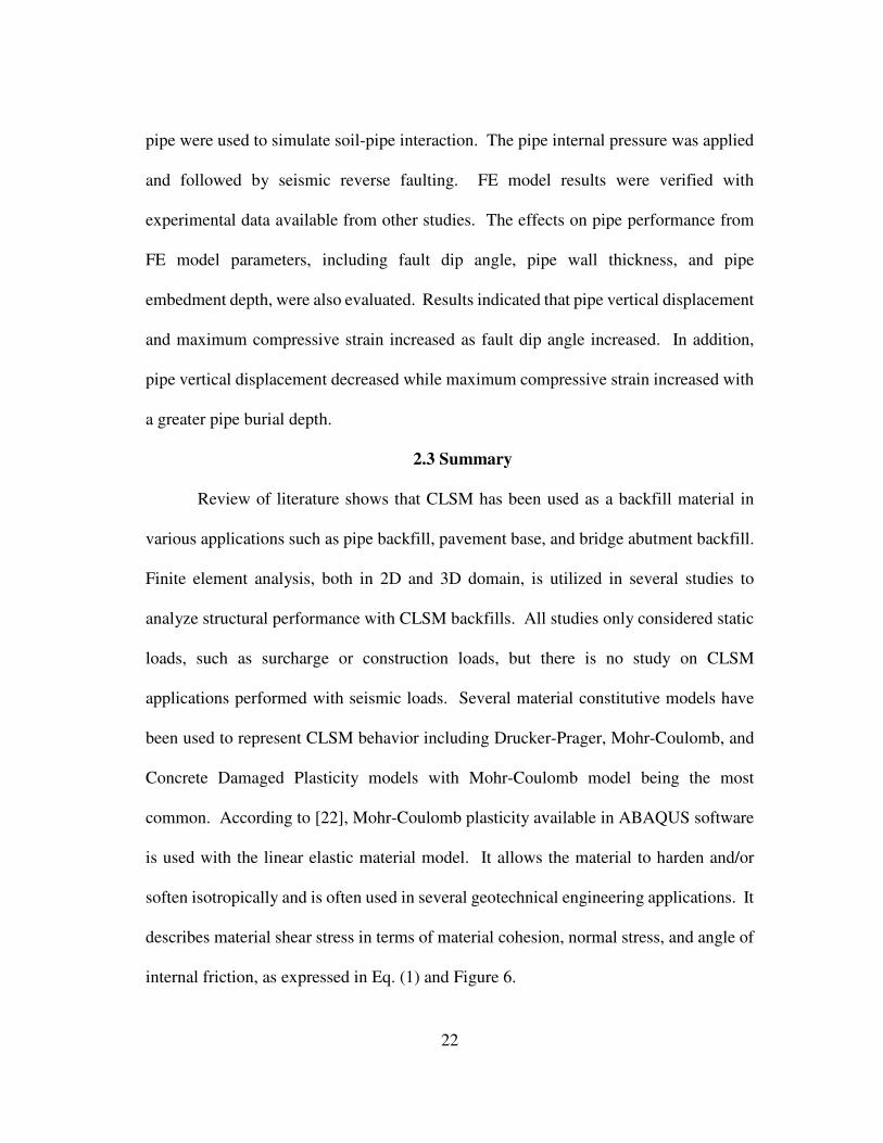
1.1.2 Controlled Low-Strength Material (CLSM)
With several drawbacks on the conventional pipe installation method, Controlled
Low-Strength Material (CLSM) has been increasingly used as an alternative to
compacted soils to backfill pipelines. Other CLSM applications include void filling,
pavement base, structural fill, bridge approach backfill, etc. Figure 2 shows a typical
pipe installation with CLSM backfill.
Figure 2: Buried pipe with CLSM backfill

3
CLSM, frequently referred to as flowable fill, is a group of self-consolidating
cementitious materials that are highly flowable in their fresh state and are solid in the
final state providing a uniform support to pipelines. CLSM mixtures typically consists
of cementitious materials, fine and/or coarse aggregates, and water. There are a large
number of studies that successfully include several waste materials and by-products in
CLSM mixture such as fly ash, quarry fines, synthetic gypsum, foundry sand, cement
kiln dust, wood ash, scrap tire, etc. [3-5]. As stated in the American Concrete Institute
(ACI) committee 229 report [6], CLSM is being used more and more as a backfill
material for buried pipes due to its inherent advantages compared to compacted soils.
Some of the advantages include shorter construction time, less inspection required, ease
of placement, improvement in worker safety and pipe settlement, and being
environment-friendly materials. Although using CLSM a backfill material for
underground pipelines has several benefits, their performance in seismic zones are not
sufficiently evaluated.
1.1.3 Seismic Phenomena
There are several reports available, e.g. [7-9], regarding pipeline damages caused
by different earthquake events. Seismic wave propagation and permanent ground
deformations are among the causes of underground pipeline failures. Permanent ground
deformations can occur in several forms, such as fault rupture, liquefaction, settlements,
and landslide. Based on a study by Eguchi [10] evaluating the pipeline damages as a
result of the 1971 San Fernando earthquake, it concluded that almost half of the total
damage occurred in the areas where fault rupture was observed. Therefore, this study

4
mainly focused on buried pipelines subject to seismic wave propagation and seismic fault
rupture.
1.1.3.1 Seismic Wave Propagation
An earthquake event generates seismic waves that propagate through the earth’s
crust. According to [11], there are two major wave type; 1) body waves and 2) surface
waves. Body waves consist of P-wave, also known as compressional wave, and S-wave,
or secondary wave. P-wave is the fastest of all wave types and can travel through any
medium. S-wave is slower than P-wave and can only travel through solid medium.
There are two types of surface waves; 1) Love waves and 2) Rayleigh waves. Just like
its type, surface waves travel at the ground surface with side-to-side action for Love
waves travel at the ground and with the combined actions, up-down and side-to-side, for
Rayleigh waves. Figure 3 shows types of seismic waves.[12]
In this study, the selected earthquake event was Loma Prieta earthquake occurred
on October 17, 1989 in San Francisco Bay area. The seismic ground acceleration records
were obtained from Center for Engineering Strong Motion Data (CESMD) [13]. The
earthquake was caused by a slip along San Andrea fault with the recorded magnitude of
6.9. Figure 4 shows time-history of ground displacement, velocity, and acceleration in
all directions for this earthquake event at the record station on Eureka Canyon Road in
Corralitos, California [13].

5
Figure 3: Types of seismic waves [12]
Figure 4: 1989 Loma Prieta earthquake seismic record [13]

6
1.1.3.2 Seismic Fault Rupture
Fault rupture is the displacement that happens as a result of a sudden movement
of the earth’s crust. Fault ruptures are categorized by the direction of movement, such
as normal-slip, strike-slip, reverse-slip, and oblique-slip fault, as shown in Figure 5.
Figure 5: Seismic fault types [14]
Various researchers studied pipelines subjected to different fault rupture types.
In 1975, Newmark and Hall [15] proposed a simplified analysis method for a pipeline
subject to a strike-slip fault using a beam-type approach considering only pipe tensile
strain. Their approach was extended by Kennedy et al. [16] in 1977 considering flexural
deformations and soil-pipe interface lateral interactions. Wang and Yeh [17] further
developed this analysis in 1985 with a beam on elastic foundation approach. In 1998,

7
Takada et al. [18] studied pipeline response to normal and reverse faults and found that
pipelines are more vulnerable to reverse fault due to local buckling. Failure analysis of
a pipe crossing a fault is very complex. It involves several factors such as soil-pipe
interaction, material nonlinearity, large deformations, and local failures. Due to this
complexity several researches, e.g. [19-21], also utilized a three-dimensional (3D) finite
element analysis (FEA) approach to analyze performance of underground pipelines
subjected to a fault rupture.
1.1.4 Finite Element Modeling
ABAQUS software was used in this study to create 3D FE models for analyzing
buried steel pipelines embedded in CLSM when subjected to seismic wave propagation
as well as reverse-slip fault rupture. Linear and nonlinear material behaviors were
considered. For linear (or elastic) analysis, three material properties are required; 1) unit
weight, 2) Young’s modulus (E), and 3) Poisson’s ratio (υ).[22] For nonlinear (or
inelastic) analysis, three material constitutive models were considered; 1) Mohr-
Coulomb plasticity model, 2) Drucker-Prager model, and 3) concrete damaged plasticity
(CDP) model. According to [22], Mohr-Coulomb plasticity model uses the classical
Mohr-Coulomb yield criterion. It allows the material to harden and/or soften
isotropically, and is suitable in several geotechnical engineering applications. Drucker-
Prager model is applicable for the material that becomes stronger as the pressure
increases (or pressure-dependent yield). It also allows for volume change with inelastic
behavior. Concrete damaged plasticity model is often used for modeling concrete or
quasi-brittle materials. Seismic wave propagation was applied in FE models by using

8
body force that considers the mass of defined materials with applied ground acceleration
time-history of the selected earthquake event in any direction (X, Y, or Z). For reverse-
slip fault rupture, displacements were applied in the upward direction along the fault
plane. In all FE models, seismic loads were applied after application of gravitational
forces.
1.2 Research Objective
The main research objective was to improve earthquake resistance of buried
pipelines preventing loss to human life as well as reducing economic impact by:
Evaluating the use of CLSM mixtures to backfill pipelines with its inherent
advantages for equal or better earthquake resistance compared to conventional
compacted soil backfill.
Providing recommendations on 3D FE modeling parameters and material
properties of CLSM for optimum earthquake resistance.
1.3 Scope and Rationale
This study utilized finite element analysis in a 3D domain using ABAQUS
software to determine the performance of buried steel pipes embedded in CLSM backfill
compared to compacted soil backfill. At the beginning, literature review was conducted
to evaluate studies previously performed regarding this subject. Then, buried pipes
embedded in soil and CLSM backfills subject to two types of seismic failure modes were
analyzed, 1) seismic wave propagation and 2) seismic reverse-slip fault rupture.
For buried pipes subject to seismic wave propagation, the study started by
evaluating the existing ASCE guidelines for seismic design of buried pipelines and its

9
design limitations. The 3D FE models with elastic material behavior matching design
assumptions in the ASCE guidelines were developed to investigate the seismic
performance of a straight pipe axially free at both ends. Several FE model parameters
were evaluated for their effects on a pipe stress prediction, including soil-pipe
interaction, boundary condition, FE model dimensions, friction coefficients at interfaces,
relationship between soil spring stiffness and material Young’s modulus, and FE model
dimension scale factor. After setting the FE model parameters to match the axial stress
predicted by the ASCE guidelines, the developed FE model was then utilized to evaluate
the pipe seismic performance of various soil and CLSM backfill materials. In addition,
the developed FE model was used to investigate the pipe seismic performance of other
conditions that are not addressed in the ASCE guidelines, such as the effect from three-
directional seismic wave applied simultaneously or the effect from pipe having a rigid
connection at one end. Next, the effect on the pipe axial stress from non-linear material
behavior was investigated including the discussion on various FE model parameters in
inelastic range, such as the use of soil spring stiffness or dashpot element at FE model
boundaries.
For buried pipes subject to seismic reverse-slip fault rupture, the study first
developed a 3D non-linear FE model with model parameters matching a full-scale
laboratory testing performed by Jalali et al. [23]. Those model parameters included FE
model dimensions, steel pipe diameter and thickness, pipe and soil backfill properties,
boundary conditions, and total applied fault movement. Maximum pipe longitudinal
strain, maximum pipe deformation, and pipe deformation shape were compared to

10
experimental data reported by [23] for FE result verifications. Various FE model
parameters were evaluated for their effects on FE model results including CLSM trench
continuity through a fault plane and CLSM-pipe interaction. Then the developed FE
model was further utilized to evaluate the pipe seismic performance for pipes with CLSM
backfilled compared to soil backfill. Other variables affecting the pipe seismic
performance were also investigated, such as material shear strength, material Young’s
modulus, and pipe diameter-to-thickness ratio.
1.4 Research Significance
Although consequences of pipe failures during a seismic event could be
catastrophic, the available ASCE guidelines are limited in assumptions and are only valid
for buried pipes in compacted soil backfill under seismic wave propagation. This study
discussed the effects of several parameters of 3D FE models on stress predictions and
established an FE model matching the ASCE guideline. The developed FE model was
then used to analyze the seismic performance of pipes with various CLSM backfills and
provided a design tool to engineers to use in conditions that cannot be analyzed with the
ASCE guidelines. In addition, this study evaluated the seismic performance of steel
pipes embedded in CLSMs when subjected to a reverse-slip fault including the
discussion on the effect of various FE model parameters. This type of analysis has not
been previously performed. The research findings provided a more complete
understanding of seismic performance of underground pipelines backfilled with CLSM
and assist design engineers in specifying CLSM mixtures for backfilling applications.

11
CHAPTER 2
LITERATURE REVIEW
This chapter discusses research in the literature that has been previously
conducted on using CLSM as a backfill material. The literature on a buried pipeline
response under seismic loads is also reviewed. This chapter is divided into three sections
that mainly focus on 1) CLSM backfill applications, 2) seismic performance of buried
pipelines, and 3) conclusion.
2.1 CLSM Backfill Applications
CLSM as a backfill material has been used in several applications, such as pipe
backfill, pavement base, and bridge abutment backfill. Many studies on CLSM backfill
applications have been performed utilizing different analysis methods, including full-
scale testing, numerical analysis, and finite element analysis. The literature was
reviewed and is summarized below.
In 1997, Zhan and Rajani [24] utilized 2D plane strain FEA to determine
performance of buried pipelines embedded in different backfill materials, including soil
and CLSM, subjected to traffic loads. The research objectives were to compare FE
model results to previously collected field test data and to assess the effect on pipe
performance from various pipe embedment depths. One-half of FE models was created
due to the model symmetry. The pipe was modeled as an elastic material, but nonlinear
constitutive model Drucker-Prager was utilized for soil and CLSM backfill materials
accounting for material nonlinearities. Soil-pipe interaction was modeled with a jointed
material option in ABAQUS defining a material failure with parameters such as friction

12
angle, dilation angle, cohesion, and temperature. This approach is different from our FE
modeling techniques and could have incurred additional errors due to variations in
jointed material properties simulating this interface. Based on results, FE models
predicted higher pipe hoop strain, which could be from 2D plane strain analysis. Results
indicated that pipe embedded in CLSM yielded a lower stress and a decrease in pipe
embedment depth compared to pipe embedded in conventional soil backfills.
Masada and Sargand [25] conducted a study on the structural performance of
High Density Poly-Ethylene (HDPE) pipe using CLSM as a pipe backfill. The buried
pipe was backfilled with several lifts of CLSM and was subjected to surcharge loads.
This study included results from field experiment as well as results from FEA.
Laboratory testing on CLSM properties was previously performed and were used for
CLSM properties in FEA. It was assumed that there was no separation between CLSM
and pipe considering fully bonding to the pipe from CLSM. This approach is different
from our research that soil-pipe separation was considered. The assumption of no
separation may be valid for some scenarios, e.g. under surcharge loads or small
anticipated deflections/stresses, but it may not be applicable for an interface subjected to
seismic loads since large ground movements are likely to occur. FE model parametric
study was not performed. The results showed that FE models over-predicted the pipe
deflections and stresses, which could have been caused by variations in CLSM material
properties used in the field and in the FE models. Results also indicated that under
loadings pipe installed in CLSM backfill experienced lower deflections and stresses
compared to pipe installed in conventional soil backfill.

13
In 2014, Dezfooli et al. [26] carried out field tests on a large steel buried pipeline
backfilled with CLSM subjected to compaction forces during installation. Three steel
pipes, 84-inch pipe outside diameter (D), embedded in three different trench
configurations were tested using CLSM as a pipe bedding and pipe backfill. Trench
configurations included 1) trench width of (D + 36”) backfilled with CLSM up to 0.3D
for Test 1, 2) trench width of (D + 12”) backfilled with CLSM up to 0.7D for Test 2, and
3) trench width of (D + 18”) backfilled with CLSM up to 0.7D for Test 3. After CLSM
backfill placement, the trenches were backfilled with compacted native soils on top of
the CLSM layer up to the ground surface. 3D nonlinear finite element models were also
developed in this study. Native soil materials were modeled using Mohr-Coulomb
constitutive model and CLSM was modeled with Concrete Damaged Plasticity model.
Lateral loads induced by compactions were calculated based on at-rest lateral pressure.
Loads were then applied to FE models using the equivalent thermal loading based on
material thermal expansion coefficients and followed by surcharge load. Field test
results were in agreement with results obtained from the FE models indicating that the
developed FE model could be further used to predict pipe performance in different
backfill materials as well as different trench configurations.
Alizadeh et al. [27] performed a full-scale laboratory test of a bridge abutment
backfilled with CLSM subjected to surcharge loads. The study also carried out a
nonlinear 3D FEA to be compared with experimental results in terms of bearing pressure,
vertical and lateral displacements, and axial forces in anchors. CLSM was modeled with
Concrete Damaged Plasticity constitutive model. After the result verification, the

14
developed FE model was then used to evaluate the influence on structural performance
of the bridge abutment from various CLSM curing age and curing temperature. Results
showed that bearing pressure of the bridge abutment increased as CLSM cured longer
and at higher temperatures, which is the influence from CLSM compressive strength. In
our research, CLSM curing age and curing temperature were not considered. CLSM
properties at 28-day were utilized.
In 2018, Abdel-Rahman et al. [28] conducted a study on buried pipes embedded
in CLSM backfill subjected to traffic loads. Finite element analysis (FEA) in a 2D
domain, plane strain, was utilized for this study. FE model dimensions were provided,
but there was no discussion on the process used to select FE model dimensions. Mohr-
Coulomb constitutive model was used for both CLSM backfill and in-situ surrounding
soils. Mohr-Coulomb constitutive model is commonly used for considering material
nonlinearities in several studies, especially for granular soils, and was also utilized in our
FE models. Soil-pipe interaction was modeled with friction contact. This same soil-
pipe interaction was implemented in our research. Two pipe types, concrete and flexible
PVC pipe, were considered in the study. Results indicated that pipe vertical stress,
horizontal stress, and bending moment on flexible PVC pipe from traffic loads were
generally lower than concrete pipe.
2.2 Seismic Performance of Buried Pipelines
2.2.1 Buried Pipelines Subjected to Seismic Wave Propagation
Design guidelines are available for researchers to design buried pipeline
subjected to seismic wave propagation. Other analysis methods, including numerical

15
analysis and finite element analysis, are also available for assessing buried pipeline
performance. The literature was reviewed and are summarized below.
In 1984, American Society of Civil Engineers (ASCE) published the Guidelines
for the Seismic Design of Oil and Gas Pipeline Systems [29]. The document provides a
detailed background of seismic hazards and design guidelines and considerations for
both aboveground and buried pipelines. For buried pipelines, different seismic failure
modes are discussed including seismic wave propagation and permanent ground
deformation. The analysis method outlined in ASCE guideline for pipes under seismic
wave propagation was adopted from a study by Newmark [30]. This method assumes a
straight buried pipe axially free at both ends. The analysis method was applicable only
for pipelines embedded in soils. In addition, it cannot be used with pipelines subjected
to three-directional seismic waves or pipelines rigidly connected to a structure at one
end.
Lee et al. [31] analyzed buried steel pipeline under seismic wave propagation
utilizing FEA for both straight pipe and pipe with bend configurations. Soil-pipe
interaction was modeled with a series of nonlinear soil springs, which is different from
our FE modeling techniques that use friction contact. Multi-directional seismic wave
was also considered for various earthquake events. Only pipes embedded in soils were
analyzed. The effect on pipe response from several FE model parameters, including pipe
types, end conditions, soil characteristics, and pipe embedment depths was evaluated.
Results showed that pipe strain at the fixed end was always higher than the pinned end,

16
and was approximately 10 times higher than the strain at the mid-length of the pipe. In
addition, pipe strain decreased with a larger pipe embedment depth.
In 2010, Lee [32] performed a study on a flexible buried pipeline under traffic
load and seismic wave propagation using FEA in a 3D domain. Parametric studies on
FE model mesh size, pipe length, and pipe embedment were also performed. The study
was limited to pipelines embedded in soils. Mohr-Coulomb constitutive model was
utilized for surrounding soils. The study assumed fully bonded interface for soil-pipe
interaction, which does not allow pipe sliding or separation. This soil-pipe interface
assumption is not realistic and may be too conservative since all seismic loads from wave
propagation would be transferred to the pipe. Results showed that as the pipe was
installed with a greater embedment depth, the pipe settlement decreased under traffic
loads. Also, pipe stress was generally higher at the fixed end compared to the free end.
Yang and Zhang [33] conducted a study on a concrete buried pipeline embedded
in various soil types subjected to three-dimensional seismic wave propagation. This
study also assumed that there is no slip between soil and pipeline whereas our research
utilized friction contact allowing slip and separation. Although the study considered
three-dimensional seismic wave, each seismic wave direction was applied independently
to determine the effect on the pipe seismic response. They found that under seismic
wave propagation, pipe axial stress is much higher compared to pipe bending stress. The
analysis was performed using 3D FEA, but there was no discussion on how FE model
dimensions were chosen for the study.

17
In 2014, Sahoo et al. [34] evaluated the seismic response of buried single pipe
and buried two parallel pipes embedded in soils subjected to seismic wave propagation
using 3D FEA. There was no discussion on how FE model dimensions were selected.
Soil-pipe interaction was modeled with a jointed material considering cohesion, friction
angle, and assumed strength reduction factor, similar to an approach utilized in the study
by Zhan and Rajani [24]. Seismic wave excitation was applied only in one direction
perpendicular to pipelines. The effect on seismic performance from pipe embedment
depth and spacing between two parallel pipes was evaluated. For both pipe
configurations, results indicated that pipe displacements and stresses decreased with
greater pipe burial depths. For two parallel pipes installed at varying spacing, results
showed that pipe stresses increased as pipe spacing increased. A study of buried
pipelines subjected to permanent ground deformation was also included. It was modeled
by applying lateral pipe bending, single curvature, in FE models. This assumption may
be applicable only for pipes subjected to permanent ground deformation caused by
liquefaction, settlements, or landslide but it would not be valid for seismic fault rupture
because pipe deformation shape would be a double curvature instead.
Zhang and Wang [35] proposed a numerical model for analyzing buried pipeline
subjected to seismic wave propagation. Their numerical model was an extension on the
work originally conducted by Shinozuka and Koike and was revised to be consistent with
the ASCE guidelines [29]. Zhang and Wang verified their numerical model with results
from FEA. The study included three different pipe configurations including 1) a straight
pipe, 2) a pipe with 90 degree right-angle bend, and 3) a pipe with tee connection. The

18
pipe was connected with a series of soil springs as computed from the ASCE guidelines.
The study was only limited to buried pipe embedded in soils and did not consider multi-
direction seismic wave. Results predicted by the proposed numerical model agreed well
with FEA results. It was also found that strain in a straight pipe dominated the design
with a small ground strain where there is no slippage between soil and pipe. At a larger
ground strain where slippage occurs, maximum strain is located near pipe bends and tees.
2.2.2 Buried Pipelines Subjected to Seismic Fault Rupture
Permanent ground deformation, specifically caused by seismic fault rupture, is
among the sources to buried pipeline failures. A large number of studies have been
conducted on buried pipelines subjected to various seismic fault rupture types, such as
normal-slip, strike-slip, reverse-slip, and oblique-slip fault. In 1998, Takada et al. [18]
studied pipeline response to normal and reverse faults and found that pipelines are more
vulnerable to reverse fault due to pipe local buckling failure. Therefore, the literature,
mainly focusing on buried pipelines subjected to reverse-slip fault rupture, was reviewed
and are summarized below.
In 2011, Joshi et al. [36] proposed a FE model to analyze buried pipelines under
reverse fault motion. The pipe was modeled using linear beam elements supported by a
series of nonlinear soil springs representing soil-pipe interaction. Pipe internal pressure
was not considered in this study. Also, pipe local buckling and large deformation were
ignored due to a limitation on beam elements representing steel pipes. The influences
on pipe response from pipe crossing angle, fault dip angle, soil spring characteristic, pipe
diameter, and pipe embedment depth were determined. Results showed that pipe strain

19
increased as pipe crossing angle increased, with the maximum values at the angle of 90º.
Pipe compressive strain was lower for pipe backfilled with loose soil compared to dense
backfill. In addition, pipe compressive strain increased as pipe embedment depth
increased.
Tarinejad et al. [21] studied seismic response of buried steel pipelines embedded
in soils subjected to reverse-slip fault rupture using a nonlinear 3D FEA. Gravitational
forces were first applied to FE models followed by internal pipe pressure before applying
seismic faulting. Mohr-Coulomb constitutive model and friction contact were adopted
for FE models, which are the same as our FE modeling techniques. The study neither
provides a discussion on selected FE model dimensions nor FE model result verification.
Results showed that at the same amount of fault movement, pipe with a higher D/t ratio
exhibited a lower pipe displacement and had less elements that went beyond elastic
range. In addition, pipe stresses decreased as fault angle increased. Although pipe
internal pressure, equal to 40% of pipe maximum design pressure, was considered, the
study did not discuss its effect of pipe performance.
In 2016, Zhang et al. [37] studied a seismic performance of buried pipelines
embedded in soil backfill in rock stratum subjected to reverse faulting. The study was
carried out utilizing 3D FEA. Shell elements were employed for steel pipelines. FE
model dimensions were provided but there was no discussion on the process used to
select these dimensions. The FE models were applied with gravity and internal pressure
loadings, simultaneously, at the beginning. Then, seismic reverse faulting was applied
to the models. Material nonlinearities were considered in this study using Mohr-

20
Coulomb constitutive model for both soil and rock. Although friction contact was
utilized on all interfaces, only one value of friction coefficient was specified. Our
research defined different friction coefficients for different material interfaces. The
effects on pipe strain and deformation from pipe internal pressure, total fault
displacement, pipe wall thickness, and pipe embedment depth were determined and
discussed. Results showed that as internal pressure increased, pipe wall wrinkles
appeared in more locations, which could be an influence of increasing pipe stiffness.
Also, pipe deformation and stress increased as fault displacement increased.
Jalali et al. [23] conducted a full-scale laboratory testing on 4” and 6” buried steel
pipes installed in a sand split-box subjected to 0.6 meter vertical movement along an
inclined plane simulating seismic reverse fault rupture. A nonlinear 3D FEA was also
carried out. Results from FE models were compared to experimental results. Material
nonlinearities were modeled using Mohr-Coulomb constitutive model. In addition,
friction contact was utilized for soil-pipe interaction. Our research uses the same FE
modeling techniques. The study was limited to steel pipes embedded in soil. Both pipes
are 4 mm thick having diameter to thickness ratio (D/t) of 26 and 38, for 4” and 6” pipe,
respectively. Experimental results showed that both pipes exhibited “diamond-shape”
buckled section matching FE results. Results also showed that pipe with lower D/t ratio
experienced higher strain, but reached the pipe buckling at a larger fault movement. FE
results slightly over predicted the maximum pipe longitudinal strains but simulated
similar pipe buckled locations to experimental results.

21
Xu and Lin [38] utilized a FEA based on Vector Form Intrinsic Finite Element
(VFIFE) method to assess buried pipe performance subjected to reverse fault rupture.
The pipe was modeled as 3D triangular shell elements near the fault plane connected
with beam elements elsewhere along the pipe. The shell elements were used to capture
severe deformation. In our research, 8-node brick elements were utilized for steel
pipelines. A study by Sadowski and Rotter [39] indicated that using shell elements
generally reduced computational runtime up to a pipe radius to thickness ratio of 25, but
both brick and shell elements provided a comparable result accuracy. Pipeline failure
was identified based on three different criteria 1) ultimate tensile strain, 2) local buckling,
and 3) pipe distortion at the cross-section. Soil-pipe interaction was modeled by
connecting pipe elements with a series of soil springs. FE model results were compared
to experimental data available from other studies. After the result validation, the
developed models were utilized to evaluate the effect on pipe performance from pipe
crossing angle and fault dip angle. Results showed that higher pipe deformation and
pipe stress occurred as pipe crossing angle increased, with the maximum values at the
angle of 90º. In addition, pipe axial stress was higher with a smaller fault dip angle while
pipe bending stress decreased.
In 2017, Liu et al. [40] investigated buckling failure of buried steel pipelines
subjected to reverse fault rupture using FEA. Two buckling failure modes as defined in
Canadian Standards Association (CSA), CSA Z662 [41]. The pipe was modeled with
elbow elements available in ABAQUS software, which is similar to shell elements but
allows more complex deformation pattern. The nonlinear soil springs connected to the
22
pipe were used to simulate soil-pipe interaction. The pipe internal pressure was applied
and followed by seismic reverse faulting. FE model results were verified with
experimental data available from other studies. The effects on pipe performance from
FE model parameters, including fault dip angle, pipe wall thickness, and pipe
embedment depth, were also evaluated. Results indicated that pipe vertical displacement
and maximum compressive strain increased as fault dip angle increased. In addition,
pipe vertical displacement decreased while maximum compressive strain increased with
a greater pipe burial depth.
2.3 Summary
Review of literature shows that CLSM has been used as a backfill material in
various applications such as pipe backfill, pavement base, and bridge abutment backfill.
Finite element analysis, both in 2D and 3D domain, is utilized in several studies to
analyze structural performance with CLSM backfills. All studies only considered static
loads, such as surcharge or construction loads, but there is no study on CLSM
applications performed with seismic loads. Several material constitutive models have
been used to represent CLSM behavior including Drucker-Prager, Mohr-Coulomb, and
Concrete Damaged Plasticity models with Mohr-Coulomb model being the most
common. According to [22], Mohr-Coulomb plasticity available in ABAQUS software
is used with the linear elastic material model. It allows the material to harden and/or
soften isotropically and is often used in several geotechnical engineering applications. It
describes material shear stress in terms of material cohesion, normal stress, and angle of
internal friction, as expressed in Eq. (1) and Figure 6.

23
� = � + � tan(∅) Eq. (1)
Where: τ = shear stress on the failure plane
c = material cohesion
� = normal stress on the failure plane
ϕ = angle of internal friction
Figure 6: Mohr-Coulomb plasticity model [22]
For studies on CLSM as a pipe backfill material, various assumptions were taken
on the soil-pipe interaction. Some studies considered no slip or separation assuming full
bonding between CLSM and pipe. The assumption may be applicable for some
scenarios, e.g. under surcharge loads or small anticipated deflections/stresses, but it may
not be valid for large ground movement, e.g. under seismic loads. Several studies
considered friction contact that allows slip and separation, which is more realistic
behavior and was adopted in our research.

24
For buried pipelines subjected to seismic wave propagation and seismic fault
rupture, specifically reverse-slip fault, a large number of studies are available, but all of
them only considered pipes embedded in soils. No study has been performed for pipes
embedded in CLSM under seismic loads. In addition, researchers utilized 3D FEA for
analyzing the performance of buried pipelines subjected to seismic loading conditions,
but there is a significant variation in FE model dimensions used in those studies. The
process used to select FE model dimensions and their effects on the results are typically
not discussed. Furthermore, several studies with FEA approach without conducting a
full-scale laboratory validated their results with experimental data conducted by others
before the verified FE models were used for further analysis. This approach was also
adopted in our research.

25
CHAPTER 3
BURIED PIPELINES SUBJECT TO SEISMIC WAVE PROPAGATION
3.1 Introduction
This chapter focuses on seismic performance of pipelines embedded in CLSM
when subjected to seismic wave propagation. This study utilized a 3D finite element
model to compare the seismic performance of pipelines embedded in CLSM to the
performance of pipelines embedded in compacted soils. The study was carried out in
two phases, 1) with the design assumptions that all materials, including steel pipe,
backfill material, and in-situ soil, remain in elastic range when subjected to seismic wave
propagation, and 2) with the design assumptions accounting for non-linear material
plasticity (inelastic range).
3.2 Research Methodology with Elastic Materials
The study started with the evaluation of available design guidelines for designing
pipelines when subjected to seismic wave propagation. Then, FE models in 3D domain
were developed using ABAQUS software for a buried steel pipe in soil backfill with the
same design assumptions of the ASCE guidelines [29], i.e. infinitely long pipe with free
ends. The effects of model parameters, such as soil-pipe interaction, boundary condition,
FE model dimensions, friction coefficients at interfaces, and soil spring used at
boundaries, on the pipe axial stress predictions were evaluated. Later, the FE model
parameters were set to obtain similar stress predictions as [29] for pipes buried in soils.
The developed model with set parameters was further used to evaluate 1) the seismic
performance of pipes embedded in CLSM backfills, 2) the effect on pipe seismic

26
performance from seismic wave applied three directions simultaneously, and 3) pipe end
conditions. A pipe axial stress value was mainly used to evaluate the seismic
performance of pipelines. A lower pipe axial stress indicates a better pipeline
performance under seismic wave propagation.
3.2.1 ASCE Guidelines
There are several design guidelines available for designing buried steel pipes
under various seismic failure modes such as permanent ground deformation,
liquefaction, landslide, or fault rupture. However, there are only a few design guidelines
available for the buried pipes subject to seismic wave propagation. These guidelines are
all either modified or adopted from ASCE Guidelines for the Seismic Design of Oil and
Gas Pipeline Systems [29] dated back in 1984 which is based on a study by Newmark
[30].
When a buried pipeline is subject to seismic wave propagation, seismic forces
get transferred to the pipeline through friction at the soil-pipe interface. According to
[29], for an infinitely long pipe free on both ends, the maximum force transfer occurs at
the maximum seismic ground strain, g, given by Eq. (2), and the maximum friction force
per unit length, tu, at soil-pipe interface for a cohesionless soil can be determined from
Eq. (3):
=����
� �
Eq. (2)
�� = �
2 � � � (1 + ��) tan � Eq. (3)
Where: g = maximum seismic ground strain

27
Vmax = maximum ground velocity
C = seismic wave-propagation velocity
� = ground strain coefficient
tu = maximum friction force per unit length
Ko = coefficient of soil pressure at rest
H = depth from the ground surface to center of the pipeline
D = Pipeline outside diameter
γ = effective unit soil weight
δ = interface angle of friction
Based on [29], Goodling [42] provided a set of equations to determine the maximum
axial force of the pipeline, Fmax, for a straight configuration free at both ends, given by
Eq. (4):
���� = �� �′ Eq. (4)
Where: Fmax = maximum axial force of the pipeline
L′ = effective friction length
It should be noted that the ASCE guidelines are only applicable for pipes
embedded in soils and cannot be used for different backfill materials such as CLSM.
Another limitation of the ASCE guidelines is that they are only valid for an infinitely
long pipe free at both ends and under one directional wave propagation. In addition, the
ASCE guidelines cannot be used to estimate stresses if the pipe is rigidly connected to a
structure at one end or if the pipe is subject to seismic waves in three directions
simultaneously.

28
3.2.2 3D Finite Element Models
In this study, FE models in 3D domain were developed to investigate various
effects on the pipe performance subject to seismic wave propagation as outlined earlier.
The developed 3D FE model generally consists of a steel pipeline component embedded
in a trench of backfill material surrounded by in-situ soil. A steel pipeline was modeled
using linear hexahedral element (C3D8R) whereas backfill material and in-situ soil were
modeled using linear wedge elements (C3D6). Smaller mesh sizes, as small as 0.25D
(where D is the pipe outside diameter), were specified for the steel pipeline and backfill
materials for more accurate results. Larger mesh sizes, as large as 2D, were defined for
in-situ soil where no results were extracted. Half-sized models were used due to model
symmetry to minimize computational run-time. Figure 7 shows an example of a
developed FE model consisting of all model components.
Figure 7: Developed 3D FE model for pipe subject to seismic wave propagation

29
FE model parameters that were used in this study are listed below:
Equations provided in the ASCE guidelines assume elastic material properties.
Therefore, steel pipeline, backfill, and in-situ soil material properties were kept in
elastic range.
Steel pipe: API-5LX-60 Grade 60 steel pipe with a 609.6 mm [24 in.] in pipe
outside diameter, 9.53 mm [0.375 in.] in thickness, and pipe embedment depth of
1524 mm [60 in.] to the top of the pipe.
Backfill trench dimensions: full width trench of 1828.8 mm [72 in.], or 3D (1.5D
was modeled due to model symmetry) and trench depth of 2438.4 mm [96 in.], or
4D.
Properties of soil and CLSM as backfill materials investigated in this study are
summarized in Table 1. Properties of four soil types, Soil (S1) thru Soil (S4), were
based on a study by Yang and Zhang [33], and three selected CLSM mixtures,
CLSM (C1) thru CLSM (C3), were evaluated by Shah [4].
Load applications: all FE models were subject to the same seismic ground
acceleration time-history of 1989 Loma Prieta earthquake event from a record
station on Eureka Canyon Road in Corralitos, California obtained from Center for
Engineering Strong Motion Data (CESMD) [13] after application of gravitational
forces.
Boundary condition for the bottom plane of FE models: pinned boundary condition
restraining displacement in all direction was placed at the bottom plane, as shown
in Figure 7, to simulate bedrock condition.

30
Table 1: Soil and CLSM properties [4, 33]
ID Material Description
as Listed in References
Density
kg/m3
[lbf/ft3]
Young’s
Modulus
MPa
[kip/in2]
Poisson
Ratio
Soil (S1) Loosely Compacted Soil 1650
[103]
6.3
[0.91] 0.20
Soil (S2) Loosely Compacted Sandy
Silt
1910
[119.2]
12.9
[1.87] 0.25
Soil (S3) Loosely Compacted Sandy
Silt
1950
[121.7]
15.3
[2.22] 0.20
Soil (S4) Loosely Compacted Sandy
Silt
2100
[131.1]
20.27
[2.94] 0.25
Soil (T1) Pseudo Soil
Evaluating Eq. (5)
2025
[126.4]
17.79
[2.58] 0.25
CLSM (C1) Mix Identity – S3 2000
[124.9]
689.5
[100] 0.13
CLSM (C2) Mix Identity – P2ʺ 1811
[113.1]
1379
[200] 0.21
CLSM (C3) Mix Identity – S2ʺ 1798
[112.2]
2757.9
[400] 0.24
3.2.3 FE Model Parametric Study
Various researchers used 3D FE model approach to analyze buried pipelines
under seismic wave propagation. However, review of the literature, e.g. [32-34, 43],
showed that there are significant variations in model dimensions used by researchers to
evaluate buried pipelines with 3D FEA. The process used to select model dimensions
and their effects on the results as well as how results compare to those obtained from
available design guidelines are typically not discussed. In this study, a total of seven (7)

31
FE model parameters was evaluated to investigate their effects on the pipe axial stress
prediction. These parameters include:
Soil-pipe interaction
Boundary condition
FE model dimensions, width and depth
FE model length with various friction coefficients
Friction coefficients at interfaces
Relationship between soil spring used at boundaries and material Young’s modulus
FE model dimension scale factor
The ASCE guidelines for an infinitely long pipe with a constant pipe cross section
under seismic wave propagation assume the peak axial stress to be uniformly distributed
along the entire pipe length. Therefore, a uniform pipe axial stress distribution along the
pipe was expected from FE model results with elastic materials.
3.2.3.1 Soil-Pipe Interaction
Based on the literature review performed earlier, two types of soil-pipe
interaction are commonly used for analyzing pipes subject to seismic wave propagation
by 3D FEA, 1) tie constraint, and 2) friction interface, as shown in Figure 8. Tie
constraint assumes that soil and pipe are fully bonded. There is no slippage or separation
between soil and pipe under seismic loads. On the other hand, friction interface only
allows seismic loads to transfer from soil to pipe by friction. The friction interface allows
pipe slippage as well as separation from soil mass. Table 2 summarizes FE model
variables used in the study of soil-pipe interaction.

32
Figure 8: Soil-pipe interaction types
Table 2: FE model variables evaluated for soil-pipe interaction
FE Model Constants
Model: Steel pipe embedded in Soil (S2) backfill
Boundary Condition: Pin at the bottom and roller support at all other planes
FE Model Variables
FE Model Width, Wd : 20D, 30D, and 40D
FE Model Depth, Dd : 10D, 15D, 20D, and 25D
FE Model Length, Ld : 50D and 100D
Soil-Pipe Interface: 1. Tie constraint (fully bonded)
2. Friction interface with coefficient of friction (f1) = 0.5
D = pipe outside diameter
3.2.3.2 Boundary Condition
FE model boundary condition used in the previous FE model parametric study,
soil-pipe interaction, was the pin type at the bottom plane and the roller type at all other
planes (front, back, and side planes as shown in Figure 7). Another type of boundary
condition evaluated in this study was soil spring, as shown in Figure 9, with FE model

33
variables summarized in Table 3. Results provided from the two types of boundary
condition were compared to determine a uniform pipe axial stress distribution along the
pipe.
Figure 9: Boundary condition types
Table 3: FE model variables evaluated for boundary condition
FE Model Constants
Model: Steel pipe embedded in Soil (S2) backfill
Soil-Pipe Interface: Friction interface with coefficient of friction (f1) = 0.5
FE Model Dimensions: Wd = 20D, Dd = 35D, and Ld = 150D
FE Model Variables
Boundary Condition: 1. Roller type
2. Spring type with stiffness (k) = 52.54 kN/m [300 lb/in]
3.2.3.3 FE Model Width and Depth
Table 4 and Table 5 show FE model variables evaluated on the effect on FE
model results from FE model width and FE model depth, respectively.

34
Table 4: FE model variables evaluated for model width
FE Model Constants
Model: Steel pipe embedded in Soil (S2) backfill
FE Model Length, Ld : 50D
Soil-Pipe Interface: Friction interface with coefficient of friction (f1) = 0.5
Boundary Condition: Spring type with stiffness (k) = 52.54 kN/m [300 lb/in]
FE Model Variables
FE Model Depth, Dd : 10D and 15D
FE Model Width, Wd : 20D, 30D, and 40D
Table 5: FE model variables evaluated for model depth
FE Model Constants
Model: Steel pipe embedded in Soil (S2) backfill
FE Model Length, Ld : 150D
Soil-Pipe Interface: Friction interface with coefficient of friction (f1) = 0.5
Boundary Condition: Spring type with stiffness (k) = 52.54 kN/m [300 lb/in]
FE Model Variables
FE Model Width, Wd : 20D, 30D, and 40D
FE Model Depth, Dd : 10D, 15D, 20D, 25D, 30D, 35D, 40D, and 45D
3.2.3.4 FE Model Length
Table 6 and Table 7 show FE model variables evaluated on the effect on FE
model results from FE model length for pipe embedded in soil backfill and in CLSM
backfill, respectively. Various soil-pipe and CLSM-pipe friction coefficients were also
evaluated in this parametric study.

35
Table 6: FE model variables evaluated for model length for soil backfill
FE Model Constants
Model: Steel pipe embedded in Soil (S2) backfill
FE Model Dimensions: Wd = 20D, Dd = 20D
Boundary Condition: Spring type with stiffness (k) = 52.54 kN/m [300 lb/in]
FE Model Variables
Soil-Pipe Interface: Friction interface with coefficient of friction (f1) = 0.3,
0.5, 0.7, and 0.9
FE Model Length, Ld : 50D, 75D, 100D, 125D, 150D, 175D, and 200D
Table 7: FE model variables evaluated for model length for CLSM backfill
FE Model Constants
Model: Steel pipe embedded in CLSM (C3) backfill
FE Model Dimensions: Wd = 30D, Dd = 25D
Boundary Condition: Spring type with stiffness (k) = 105.08 kN/m [600 lb/in]
FE Model Variables
CLSM-Pipe Interface: Friction interface with coefficient of friction (f1) = 0.3,
0.5, 0.7, and 0.9
FE Model Length, Ld : 50D, 75D, 100D, 125D, 150D, 175D, 200D, 300D, 400D,
and 500D
3.2.3.5 Friction Coefficients at Interfaces
Under seismic wave propagation, seismic loads are transferred to buried
pipelines through friction. As shown in Figure 7, in case of buried pipe with soil backfill,
only friction coefficient of soil-pipe interface (f1) was evaluated. When CLSM is used
as a backfill material, there are two interfaces with different friction coefficients that can

36
affect the pipe axial stress; 1) CLSM-pipe (f1) and 2) CLSM-soil (f2). Effects of varying
friction coefficients of both interfaces on pipe axial stresses were evaluated in this study
with FE model variables evaluated shown in Table 8.
Table 8: FE model variables evaluated for friction coefficients for CLSM backfill
FE Model Constants
Model: Steel pipe embedded in CLSM (C3) backfill
FE Model Dimensions: Wd = 30D, Dd = 25D, and Ld = 200D
Boundary Condition: Spring type with stiffness (k) = 105.08 kN/m [600 lb/in]
FE Model Variables
CLSM-Pipe Interface: Friction interface with coefficient of friction (f1) = 0.3,
0.5, 0.7, and 0.9
Soil-CLSM Interface: Friction interface with coefficient of friction (f2) = 0.2,
0.4, 0.6, and 0.8
3.2.3.6 Relationship between Material Young’s Modulus and Soil Spring Stiffness
To achieve a uniform pipe axial stress distribution along the pipe, the study
further evaluated a relationship between material Young’s modulus (E) and soil spring
stiffness value (k) used at the FE model boundaries (front, back, and side planes as shown
in Figure 7). Four selected soil types (Soil S1 thru S4) with different densities, Young’s
modulus, Poisson ratios, cohesion, and friction angles were investigated based on a study
from [33]. In-situ soil spring stiffness placed at FE model boundaries for steel pipe
embedded in CLSM backfills was also investigated. Three selected CLSM mixtures
(CLSM C1 thru C3) as evaluated by [4] were used for this study. The three selected

37
CLSM mixtures consist of fly ash, gypsum, quarry waste, and water with the following
proportions:
CLSM (C1) - Mix Identity S3: water to fly ash ratio (W/FA) of 0.61 and 15%
gypsum of fly ash by weight.
CLSM (C2) - Mix Identity P2ʺ: water to fly ash ratio (W/FA) of 0.80 and 15%
gypsum of fly ash by weight.
CLSM (C3) - Mix Identity S2ʺ: water to fly ash ratio (W/FA) of 0.80 and 10%
gypsum of fly ash by weight.
All soil and CLSM properties evaluated in this parametric study are summarized and
listed in Table 1. Table 9 and Table 10 show FE model variables evaluated on the
relationship between material Young’s modulus and soil spring stiffness value for pipe
embedded in soil backfill and in CLSM backfill, respectively.

38
Table 9: FE model variables evaluated for boundary soil spring for soil backfill
FE Model Constants
Soil-Pipe Interface: Friction interface with coefficient of friction (f1) = 0.5
FE Model Dimensions: Wd = 30D, Dd = 25D, and Ld = 200D
FE Model Variables
Model: Steel pipe embedded in Soil (S1) thru (S4) backfills
Boundary Condition:
Soil (S1): spring stiffness (K) ranging from 17.51 kN/m
[100 lb/in] to 157.61 kN/m [900 lb/in]
Soil (S2): spring stiffness (K) ranging from 122.59 kN/m
[700 lb/in] to 700.51 kN/m [4000 lb/in]
Soil (S3): spring stiffness (K) ranging from 175.13 kN/m
[1000 lb/in] to 875.63 kN/m [5000 lb/in]
Soil (S4): spring stiffness (K) ranging from 280.2 kN/m
[1600 lb/in] to 1225.89 kN/m [7000 lb/in]
Table 10: FE model variables evaluated for boundary soil spring for CLSM backfill
FE Model Constants
Soil-Pipe Interface: Friction interface with coefficient of friction (f1) = 0.5
FE Model Dimensions: Wd = 30D, Dd = 25D, and Ld = 200D
FE Model Variables
Model: Steel pipe embedded in CLSM (C1) thru (C3) backfills
Boundary Condition: Spring stiffness (K) ranging from 105.08 kN/m [600 lb/in]
to 315.23 kN/m [1800 lb/in]
3.2.3.7 FE Model Dimension Scale Factor
Larger FE model dimensions increase the computational run-time necessary for
an analysis. In this study, the effect of changing the FE model dimensions while keeping
the dimension scale factor (SF) ratios constant was evaluated for pipe embedded in soil

39
backfill (Soil S2). The developed FE model was scaled down and up by multiplying all
dimensions with 0.75 and 1.25, respectively. Overall FE model dimensions, pipe outside
diameter and thickness, pipe embedment depth, and trench dimensions were all scaled.
The soil spring stiffness placed at boundaries and soil-pipe friction coefficient remained
unchanged. This parametric study may allow engineers to minimize the computational
run-time of FE model analysis by scaling the model and understanding the FE model
size effects on model results. Table 11 shows FE model variables evaluated in this study.
Table 11: FE model variables evaluated for scale factor for soil backfill
FE Model Constants
Model: Steel pipe embedded in Soil (S2) backfill
Soil-Pipe Interface: Friction interface with coefficient of friction (f1) = 0.5
Boundary Condition: Spring type with stiffness (k) = 245.18 kN/m [1400 lb/in]
FE Model Variables
FE Model Dimensions:
(SF = 0.75) Wd = 22.5D, Dd = 18.75D, and Ld = 150D
(SF = 1.00) Wd = 30D, Dd = 25D, and Ld = 200D
(SF = 1.25) Wd = 37.5D, Dd = 31.25D, and Ld = 250D
3.2.4 Pipe Seismic Performance of Various Backfill Materials
After evaluating the effects of different FE model parameters, the parameters of
the FE model were set to obtain a similar uniform axial peak stress along the pipe as
predicted by the ASCE guidelines for pipes buried in soils. This FE model with set
parameters to match the ASCE values was then used to evaluate the pipe seismic
performance of four soils (Soil S1 thru S4) and three CLSM mixtures (CLSM C1 thru

40
C3) with their properties as listed in Table 1. This study was conducted to address one
of the limitations from using the ASCE guidelines that it cannot be used for buried pipe
embedded in CLSM. A pipe axial stress value was mainly used to evaluate the seismic
performance of pipelines. A lower pipe axial stress indicates a better pipeline
performance under seismic wave propagation.
3.2.5 Effect from One- and Three-Directional Seismic Wave
For computing pipe axial stress under seismic wave propagation, equations
provided in the ASCE guidelines only accounts for one directional wave propagation.
The developed FE model was further utilized to evaluate the effect on the pipe seismic
performance subject to three-directional seismic wave applied simultaneously. Pipes
embedded in soil backfill, Soil (S2), and CLSM backfill, CLSM (C3), were investigated
and compared to the pipe seismic performance when subjected to one-directional seismic
wave.
3.2.6 Pipe End Conditions
In many instances, buried pipelines interconnect with other components such as
above ground pipelines, storage structures, and support facilities. This pipe end
condition is considered rigid. Additional limitation of the ASCE guidelines is that they
are only valid for an infinitely long pipe free at both ends. The ASCE guidelines cannot
be used to estimate stresses if the pipe is rigidly connected to a structure at one end. For
this particular scenario, the developed FE model was used to investigate the effect on the
pipe seismic performance. The effect from three-directional seismic wave applied
simultaneously was also considered in conjunction with pipe end conditions.

41
3.3 Results and Discussions with Elastic Materials
3.3.1 ASCE Guidelines
For API-5LX-60 Grade 60 steel pipe with a 609.6 mm [24 in.] in pipe outside
diameter (D), 9.53 mm [0.375 in.] in wall thickness, and pipe embedment depth (H) of
1524 mm [60 in.] to the top of the pipe, the pipe axial stress when subjected to the 1989
Loma Prieta earthquake was computed. According to [13], the peak ground acceleration
recorded during this earthquake event was 0.643g with the maximum ground velocity,
Vmax, of 0.475 m/s [18.697 in/s] and the seismic wave velocity, C, of 462 m/s [1,515.7
ft/s]. Assuming dilatational wave only, ground strain coefficient, �, is equal to 1.0.
Using Eq. (2), the computed maximum ground strain, g, for this earthquake event is
equal to 0.0010279. From [33], soil unit weight, soil Young’s Modulus, and Poisson
ratio of a sandy silt soil were taken as 1910 kg/m3 [119.24 lb/ft3], 12.9 MPa [1871 psi],
and 0.25, respectively, as listed as Soil (S2) in Table 1. Using Eq. (3) and Eq. (4), the
calculated maximum friction force per unit length, tu, was 29.523 kN/m [2.023 kip/ft]
resulting in a peak axial stress of the steel pipeline of 50.13 MPa [7.270 ksi] for an
effective friction length, L′, of 60.96 m [200 ft].
This peak stress value was later used to set various parameters of the developed
FE model using Soil (S2) to obtain a similar uniform axial stress. After adjustments of
parameters the obtained uniform average pipe axial stress from the FE model with Soil
(S2) was equal to 49.69 MPa [7.206 ksi]. Figure 10 shows the pipe axial stress along the
pipe length obtained from the ASCE guidelines as well as from the developed FE model

42
for pipe embedded in Soil (S2) backfill. Results indicated that pipe axial stress prediction
from the developed FE model matched well with the ASCE guidelines.
Figure 10: Pipe axial stress along the pipe obtained from the ASCE guidelines and the
developed FE models
3.3.2 FE Model Parametric Study
3.3.2.1 Soil-Pipe Interaction
Two types of soil-pipe interaction, 1) tie constraint, and 2) friction interface, were
evaluated with FE model variables as shown in Table 2. Figure 11, Figure 12, and Figure
13 show the pipe axial stress along the pipe length for FE models using tie constraint for
soil-pipe interaction for FE model width (Wd) of 20D, 30D, and 40D, respectively, with
various FE model depths (Dd), varying from 10D to 25D.

43
Figure 11: Pipe axial stress along the pipe using tie constraint for soil-pipe interaction
with FE model width (Wd) of 20D for various FE model depth (Dd)
Figure 12: Pipe axial stress along the pipe using tie constraint for soil-pipe interaction
with FE model width (Wd) of 30D for various FE model depth (Dd)
0
250
500
750
1000
1250
0% 20% 40% 60% 80% 100%
Wd = 20D, D
d = 10D, L
d = 50D
Wd = 20D, D
d = 15D, L
d = 50D
Wd = 20D, D
d = 20D, L
d = 50D
Wd = 20D, D
d = 25D, L
d = 50D
0
36.3
72.5
108.8
145
181.3
Pip
e A
xia
l S
tress
(M
Pa)
Location along Pipe Length (%)
Pip
e A
xia
l Stre
ss (k
si)
Tie Constraint
0
250
500
750
1000
1250
0% 20% 40% 60% 80% 100%
Wd = 30D, D
d = 10D, L
d = 50D
Wd = 30D, D
d = 15D, L
d = 50D
Wd = 30D, D
d = 20D, L
d = 50D
Wd = 30D, D
d = 25D, L
d = 50D
0
36.3
72.5
108.8
145
181.3
Pip
e A
xia
l S
tress
(M
Pa)
Location along Pipe Length (%)
Pip
e A
xia
l Stre
ss (k
si)
Tie Constraint

44
Figure 13: Pipe axial stress along the pipe using tie constraint for soil-pipe interaction
with FE model width (Wd) of 40D for various FE model depth (Dd)
It should be noted that pipe axial stress with tie constraint for soil-pipe interaction was
well beyond the ultimate steel strength because steel pipe materials used in the developed
models was assumed to be elastic with no failure point defined. Although this may not
be a realistic material behavior, the results were only used to evaluate the effect on
uniform pipe stress distribution from the two types of soil-pipe interaction.
Figure 14, Figure 15, and Figure 16 show the pipe axial stress along the pipe
length for FE models using friction interface for soil-pipe interaction for FE model width
(Wd) of 20D, 30D, and 40D, respectively, with various FE model depths (Dd), varying
from 10D to 25D. From the results for all FE model widths, the pipe axial stress using
tie constraint for soil-pipe interaction were approximately 10-15 times higher than FE
models with friction at both pipe end and mid-pipe locations. It was also observed that
0
250
500
750
1000
1250
0% 20% 40% 60% 80% 100%
Wd = 40D, D
d = 10D, L
d = 100D
Wd = 40D, D
d = 15D, L
d = 100D
Wd = 40D, D
d = 20D, L
d = 100D
Wd = 40D, D
d = 25D, L
d = 100D
0
36.3
72.5
108.8
145
181.3
Pip
e A
xia
l S
tress
(M
Pa)
Location along Pipe Length (%)
Pip
e A
xia
l Stre
ss (k
si)
Tie Constraint

45
when using friction interface for soil-pipe interaction stress variance among FE model
depths were much less and average pipe axial stress was much closer to the value
computed from the ASCE guidelines. Therefore, it was concluded that friction interface
should be utilized for soil-pipe interaction.
Figure 14: Pipe axial stress along the pipe using friction interface for soil-pipe
interaction with FE model width (Wd) of 20D for various FE model depth (Dd)
0
30
60
90
120
150
0% 20% 40% 60% 80% 100%
Wd = 20D, D
d = 10D, L
d = 50D
Wd = 20D, D
d = 15D, L
d = 50D
Wd = 20D, D
d = 20D, L
d = 50D
Wd = 20D, D
d = 25D, L
d = 50D
0
4.4
8.7
13.1
17.4
21.8
Pip
e A
xia
l S
tress
(M
Pa)
Location along Pipe Length (%)
Pip
e A
xia
l Stre
ss (k
si)
Friction Interface

46
Figure 15: Pipe axial stress along the pipe using friction interface for soil-pipe
interaction with FE model width (Wd) of 30D for various FE model depth (Dd)
Figure 16: Pipe axial stress along the pipe using friction interface for soil-pipe
interaction with FE model width (Wd) of 40D for various FE model depth (Dd)
0
30
60
90
120
150
0% 20% 40% 60% 80% 100%
Wd = 30D, D
d = 10D, L
d = 50D
Wd = 30D, D
d = 15D, L
d = 50D
Wd = 30D, D
d = 20D, L
d = 50D
Wd = 30D, D
d = 25D, L
d = 50D
0
4.4
8.7
13.1
17.4
21.8
Pip
e A
xia
l S
tress
(M
Pa)
Location along Pipe Length (%)
Pip
e A
xia
l Stre
ss (k
si)
Friction Interface
0
30
60
90
120
150
0% 20% 40% 60% 80% 100%
Wd = 40D, D
d = 10D, L
d = 100D
Wd = 40D, D
d = 15D, L
d = 100D
Wd = 40D, D
d = 20D, L
d = 100D
Wd = 40D, D
d = 25D, L
d = 100D
0
4.4
8.7
13.1
17.4
21.8
Pip
e A
xia
l S
tress
(M
Pa)
Location along Pipe Length (%)
Pip
e A
xia
l Stre
ss (k
si)
Friction Interface

47
3.3.2.2 Boundary Condition
Two types of boundary condition, 1) roller support, and 2) soil spring support,
were evaluated with FE model variables as shown in Table 3. Figure 17 shows the pipe
axial stress along the pipe length comparing between FE models using roller supports
and soil spring supports. Results clearly indicated that using soil spring at boundaries
provided a much more uniform axial stress along the pipe length. Therefore, it was
recommended to use soil spring at all planes (front, back, and side planes) as a boundary
condition for the developed FE models.
Figure 17: Pipe axial stress along the pipe for roller and soil spring supports

48
3.3.2.3 FE Model Width
Figure 18 and Figure 19 show the pipe axial stress along the pipe length for
various FE model widths (Wd), 20D, 30D, and 40D. Two FE model depths (Dd), 10D
and 15D, were evaluated in this parametric study. Results showed that stress variance
along the pipe length among FE model widths evaluated was insignificant. Therefore, it
was concluded that FE model width does not have a significant impact to FE model
results. A minimum FE model width of 20D was recommended to minimize
computational run-time.
Figure 18: Pipe axial stress along the pipe with various FE model widths (Wd) for FE
model depth (Dd) of 10D
0
15
30
45
60
75
0% 20% 40% 60% 80% 100%
Wd = 20D, D
d = 10D, L
d = 50D
Wd = 30D, D
d = 10D, L
d = 50D
Wd = 40D, D
d = 10D, L
d = 50D
0
2.2
4.4
6.5
8.7
10.9
Pip
e A
xia
l S
tress
(M
Pa)
Location along Pipe Length (%)
Pip
e A
xia
l Stre
ss (k
si)

49
Figure 19: Pipe axial stress along the pipe with various FE model widths (Wd) for FE
model depth (Dd) of 15D
3.3.2.4 FE Model Depth
Figure 20 shows the pipe axial stress at mid-pipe location for various FE model
depths (Dd), varying from 10D to 45D. Three FE model widths (Wd), 20D, 30D, and
40D) were evaluated in this parametric study with a constant FE model length (Ld) of
150D. From the results, it was observed that the peak axial stress at mid-pipe location
increased as the FE model depth increased and started to be constant after a certain model
depth. It was also noted that the peak axial stress could be under estimated with a
shallower FE model depth. Therefore, a minimum FE model depth of 35D was
suggested.
0
15
30
45
60
75
0% 20% 40% 60% 80% 100%
Wd = 20D, D
d = 15D, L
d = 50D
Wd = 30D, D
d = 15D, L
d = 50D
Wd = 40D, D
d = 15D, L
d = 50D
0
2.2
4.4
6.5
8.7
10.9
Pip
e A
xia
l S
tress
(M
Pa)
Location along Pipe Length (%)
Pip
e A
xia
l Stre
ss (k
si)

50
Figure 20: Pipe axial stress at mid-pipe location for various FE model depth (Dd)
3.3.2.5 FE Model Length
Figure 21 shows the pipe axial stress at mid-pipe location for various FE model
lengths (Ld), varying from 50D to 200D, for piped embedded in soil backfill, Soil (S2).
Four friction coefficients of soil-pipe interaction (f1), 0.3, 0.5, 0.7, and 0.9, were
evaluated in this parametric study.
0
15
30
45
60
75
Wd = 20D, L
d = 150D
Wd = 30D, L
d = 150D
Wd = 40D, L
d = 150D
0
2.2
4.4
6.5
8.7
10.9
10D 15D 20D 25D 30D 35D 40D 45D
Pip
e A
xia
l S
tre
ss
at
Mid
Pip
e L
oc
ati
on
(M
Pa
)
FE Model Length in term of Pipe Outside Diameter (D)
Pip
e A
xia
l Stre
ss
at M
id P
ipe
Lo
ca
tion
(ks
i)

51
Figure 21: Pipe axial stress at mid-pipe location for various FE model lengths (Ld) for
pipes embedded in soil backfill
As mentioned earlier, seismic loads are transferred to buried pipelines through
friction for pipes subject to seismic wave propagation. Results showed that there is the
critical FE model length required to completely transfer the load for each friction
coefficient. The peak axial stress at mid-pipe location first increased with increasing FE
model length and decreased after it reached the critical FE model length. It was observed
that the critical FE model length decreased as the friction coefficient increased. In
addition, the maximum pipe axial stress at the critical length increased as the friction
coefficient increased. Therefore, it was recommended that a model should be created
with a sufficient FE model length depending on soil-pipe friction coefficient to capture
the peak axial stress that a pipeline could experience under seismic loads. For this study,
0
10
20
30
40
50
f1 = 0.3
f1 = 0.5
f1 = 0.7
f1 = 0.9
0
1.5
2.9
4.4
5.8
7.3
50D 75D 100D 125D 150D 175D 200D
Pip
e A
xia
l S
tre
ss
at
Mid
Pip
e L
oc
ati
on
(M
Pa
)
FE Model Length in term of Pipe Outside Diameter (D)
Pip
e A
xia
l Stre
ss
at M
id P
ipe
Lo
ca
tion
(ks
i)

52
a minimum FE model length of 200D was used for all other investigations with soil
backfill.
Figure 22 shows the pipe axial stress at mid-pipe location for various FE model
lengths (Ld), varying from 50D to 500D, for piped embedded in CLSM backfill, CLSM
(C3). The same set of selected CLSM-pipe friction coefficients (f1) were investigated.
The value of friction coefficient at CLSM-soil interface (f2) was set equal to the CLSM-
pipe friction coefficient.
Results showed that the pipe axial stress initially increased as the FE model
length increased for all CLSM-pipe friction coefficients, similar to pipe embedded in soil
backfill, and it remained constant after reaching the critical model length. Results also
indicated that the maximum pipe axial stress increased with increasing CLSM-pipe
friction coefficient. This is consistent with the ASCE guidelines, which state that seismic
forces get transferred to the pipeline through friction at the soil-pipe interface. Unlike
soil backfills, the critical FE model length did not vary with the CLSM-pipe friction
coefficient. Based on results shown in Figure 22, it was decided to use a minimum FE
model length of 200D for all other evaluations of CLSM backfills in this study.

53
Figure 22: Pipe axial stress at mid-pipe location for various FE model lengths (Ld) for
pipes embedded in CLSM backfill
3.3.2.6 Friction Coefficients at Interfaces
The effect of CLSM-soil coefficient of friction (f2) on pipe axial stresses was also
evaluated. Four values of CLSM-pipe friction coefficient (f1); 0.3, 0.5, 0.7, and 0.9, were
combined with four values of CLSM-soil friction coefficients (f2); 0.2, 0.4, 0.6, and 0.8,
in this parametric study for pipes embedded in CLSM backfill, CLSM (C3).
Figure 23 shows the average pipe axial stresses for various f1 and f2 combinations.
Results showed that for the same CLSM-pipe friction coefficient (f1), the average pipe
axial stress increased as CLSM-soil friction coefficient (f2) increased. Similarly, for the
same CLSM-soil friction coefficient (f2), the average pipe axial stress increased as
CLSM-pipe friction coefficient (f1) increased.
0
10
20
30
40
50
f1 = 0.3
f1 = 0.5
f1 = 0.7
f1 = 0.9
0
1.5
2.9
4.4
5.8
7.3
50d 75d 100d 125d 150d 175d 200d 300d 400d 500d
Pip
e A
xia
l S
tress
(M
Pa
)
FE Model Length in term of Pipe Outside Diameter (d)
Pip
e A
xia
l Stre
ss
(ksi)

54
Figure 23: Effect on pipe axial stress from CLSM-pipe (f1) and CLSM-soil (f2) friction
coefficients at interfaces
3.3.2.7 Relationship between Material Young’s Modulus and Soil Spring Stiffness
Based on the results from the parametric study of FE model boundary condition,
it showed that use of soil springs was necessary at the front, back and side boundary
planes, as shown in Figure 7, to achieve a uniform pipe axial stress distribution along the
pipe. In this study this issue was further investigated to establish a relationship between
material Young’s modulus (E) and soil spring stiffness value (K) used at the FE model
boundaries to obtain a uniform stress distribution. Four soil backfills, Soil (S1) thru Soil
(S4), and three CLSM mixtures, CLSM (C1) thru CLSM (C3), with different Young’s
modulus (E) values as shown in Table 1. Soil spring stiffness value (K) evaluated for
each backfill material was summarized in Table 9 and Table 10 for soil and CLSM
backfills, respectively.
12
14
16
18
20
22
24
f1 = 0.3
f1 = 0.5
f1 = 0.7
f1 = 0.9
1.7
2
2.3
2.6
2.9
3.2
3.5
0 0.2 0.4 0.6 0.8 1
Avera
ge
Pip
e A
xia
l S
tre
ss (
MP
a)
CLSM-Soil Friction Coefficient (f2)
Avera
ge
Pip
e A
xia
l Stre
ss (k
si)

55
For each backfill material, axial stresses along the pipe length (σx) were plotted
for each K value. The average pipe stress (�!) and stress variation, (�� " �!)#, along the
pipe were also calculated for each K value. Then, the summation of stress variance,
∑(�� " �!)#, was plotted with the K value, as shown in Figure 24 a soil with E of 6.3
MPa [0.91 ksi], Soil (S1), and for a CLSM mixture with E of 689.5 MPa [100 ksi], CLSM
(C1).
Figure 24: Stress variation curve for soil and CLSM backfills
Results showed that there was an optimum K value (Kopt) that resulted in the
minimum stress variation along the pipe for each backfill material. Table 12 thru Table
15 show the summation stress variance for each K value evaluated for different soil

56
backfills investigated in this study. The optimum K value (Kopt) was selected based on
the lowest value of the summation stress variance and was highlighted in those tables.
Table 12: Soil spring stiffness and sum of stress variance for Soil (S1)
Backfill Material
Soil Spring
Stiffness
(K)
lb/in
Avg. Pipe
Axial Stress
(%&) kip/in2
Sum of Stress
Variance
Ʃ(%' " %&)(
Soil (S1)
E = 6.3 MPa [0.91 ksi]
100 6.192 43.980
200 6.568 18.459
300 6.727 12.065
400 7.133 3.308
500 7.352 0.934
600 7.134 1.386
700 7.379 0.426
800 8.007 1.354
900 8.289 3.594
* highlighted row indicates the optimum K value (Kopt) for this backfill material

57
Table 13: Soil spring stiffness and sum of stress variance for Soil (S2)
Backfill Material
Soil Spring
Stiffness
(K)
lb/in
Avg. Pipe
Axial Stress
(%&) kip/in2
Sum of Stress
Variance
Ʃ(%' " %&)(
Soil (S2)
E = 12.9 MPa [1.87 ksi]
700 6.917 13.577
800 6.854 13.328
900 6.922 9.382
1000 7.481 1.956
1100 9.703 26.106
1200 7.092 2.576
1300 7.147 1.758
1400 7.206 1.573
4000 10.365 82.949
Table 14: Soil spring stiffness and sum of stress variance for Soil (S3)
Backfill Material
Soil Spring
Stiffness
(K)
lb/in
Avg. Pipe
Axial Stress
(%&) kip/in2
Sum of Stress
Variance
Ʃ(%' " %&)(
Soil (S3)
E = 15.3 MPa [2.22 ksi]
1000 6.453 1.356
1100 6.569 1.844
1200 6.764 3.876
1300 6.093 0.807
1400 7.123 10.616
1500 6.181 2.124
1600 6.302 3.239
1700 6.455 4.579
5000 12.624 147.213

58
Table 15: Soil spring stiffness and sum of stress variance for Soil (S4)
Backfill Material
Soil Spring
Stiffness
(K)
lb/in
Avg. Pipe
Axial Stress
(%&) kip/in2
Sum of Stress
Variance
Ʃ(%' " %&)(
Soil (S4)
E = 20.27 MPa [2.94 ksi]
1600 6.422 3.036
1700 6.453 2.064
1800 6.483 1.368
1900 7.420 2.408
2000 7.595 3.819
2100 8.522 13.148
2200 8.864 17.672
7000 10.200 99.846
Next, the Kopt value obtained was plotted with soil Young’s modulus (E), as
shown in Figure 25. Results indicated that the Kopt value for a more uniform stress
distribution along the pipe length increased with increasing E values for soil backfills.
The observed empirical relationship between Kopt value and soil Young’s modulus is
given by Eq. (5) and Eq. (6) for metric and English units, respectively:
[for metric unit]: Kopt = 13.24 E + 46.382 Eq. (5)
[for English unit]: Kopt = 0.521 E + 264.85 Eq. (6)
Where: Kopt = soil spring stiffness placed at FE model
boundaries (kN/m for metric unit; lb/in for
English unit)
E = soil’s Young’s modulus (MPa for metric
unit; lb/in2 for English unit)

59
Figure 25: Relationship between soil Young’s modulus and soil spring stiffness
The Kopt value for additional soil type, referred to as Soil (T1) as listed in Table
1, with E value of 17.79 MPa [2580.2 psi] was calculated using Eq. (5) to be 281.9 kN/m
[1609.1 lb/in]. The soil properties and the computed Kopt value were then used in the
developed FE model to evaluate the variation of axial stresses along the pipe. Figure 26
shows axial stresses plotted along the pipe for Soil (T1) using computed Kopt value at
boundary planes. Results showed that a fairly uniform axial stress distribution along the
pipe was achieved for Soil (T1) when its Kopt calculated using Eq. (5) was used in the
developed FE model.

60
Figure 26: Evaluation of empirical relationship for Soil (T1)
Similar to the evaluation for soil backfills, three CLSM mixtures, CLSM (C1)
thru CLSM (C3), with different Young’s modulus (E) values were investigated for their
relationship with soil spring stiffness utilized at FE model boundaries. Table 16 thru
Table 18 show the summation stress variance for each K value evaluated for different
CLSM backfills investigated in this study. The optimum K value (Kopt) was selected
based on the lowest value of the summation stress variance and was highlighted in those
tables.
0
20
40
60
80
100
0% 20% 40% 60% 80% 100%
Soil (T1)
0
2.9
5.8
8.7
11.6
14.5
Pip
e A
xia
l S
tress
(M
Pa)
Location along Pipe Length (%)
Pip
e A
xia
l Stre
ss (k
si)

61
Table 16: Soil spring stiffness and sum of stress variance for CLSM (C1)
Backfill Material
Soil Spring
Stiffness
(K)
lb/in
Avg. Pipe
Axial Stress
(%&) kip/in2
Sum of Stress
Variance
Ʃ(%' " %&)(
CLSM (C1)
E = 689.5 MPa [100 ksi]
600 4.149 7.683
800 4.533 5.899
1000 5.045 5.981
1200 5.496 8.151
1400 5.841 10.803
1600 6.140 13.539
1800 6.359 16.519
Table 17: Soil spring stiffness and sum of stress variance for CLSM (C2)
Backfill Material
Soil Spring
Stiffness
(K)
lb/in
Avg. Pipe
Axial Stress
(%&) kip/in2
Sum of Stress
Variance
Ʃ(%' " %&)(
CLSM (C2)
E = 1379 MPa [200 ksi]
600 3.329 2.127
800 3.886 0.196
1000 4.195 1.518
1200 5.081 4.903
1400 4.936 4.476
1600 6.883 23.317
1800 5.493 12.307

62
Table 18: Soil spring stiffness and sum of stress variance for CLSM (C3)
Backfill Material
Soil Spring
Stiffness
(K)
lb/in
Avg. Pipe
Axial Stress
(%&) kip/in2
Sum of Stress
Variance
Ʃ(%' " %&)(
CLSM (C3)
E = 2757.9 MPa [400 ksi]
600 2.473 0.671
800 2.879 1.209
1000 3.248 3.166
1200 3.593 5.158
1400 3.880 7.499
1600 4.256 11.463
1800 4.440 14.173
Unlike Soils, the Kopt value for minimum stress variation along the pipe changed
only slightly for the three CLSM mixtures evaluated with different E values. Therefore,
it was concluded that the CLSM Young’s modulus value was not a significant factor
affecting the Kopt value. This could be due to the large difference in stiffness between
the CLSM mixtures and the surrounding in-situ soil as well as an increase in system
stiffness provided by CLSM trench surrounding the pipe. For all other investigations
with CLSM backfills in this study, an average Kopt value of 140.2 kN/m [800 lb/in] was
utilized.
3.3.2.8 FE Model Dimension Scale Factor
Figure 27 shows axial stresses along the pipe length for the FE model with Soil
(S2) backfill and the two scaled models with factors of 0.75 and 1.25. The average pipe
stress for the Soil (S2) backfill material was 49.69 MPa [7.206 ksi] and the average pipe

63
stresses for the down and up scaled models were 38.69 MPa [5.612 ksi] and 63.75 MPa
[9.246 ksi], respectively.
Figure 27: Pipe axial stress along the pipe for various FE model scale factors
The average pipe axial stress of the FE model scaled down with a factor of 0.75 was 78%
of the average pipe axial stress of the original model. Similarly, the average pipe axial
stress of the scaled up FE model with a factor of 1.25 was 128% of the average pipe axial
stress of the original model. Results indicated that when the FE model dimensions are
modified with a constant scale factor keeping the dimension ratios constant, the average
pipe axial stresses changed with almost the same factor. This result can be used to
minimize analysis run-time by using scaled down models.
0
30
60
90
120
150
0% 20% 40% 60% 80% 100%
Scale Factor = 0.75
Scale Factor = 1.0Scale Factor = 1.25
0
4.4
8.7
13.1
17.4
21.8
Pip
e A
xia
l S
tress
(M
Pa
)
Location along Pipe Length (%)
Pip
e A
xia
l Stre
ss
(ksi)

64
3.3.3 Pipe Seismic Performance of Various Backfill Materials
After setting the FE model parameters such as soil spring stiffness at boundaries,
minimum FE model length, and friction coefficient to match the axial stress predicted
by the ASCE guidelines when using Soil (S2) as a pipe backfill material, this developed
FE model was further utilized to evaluate the pipe seismic performance of other soil and
CLSM backfill materials, as shown in Table 1. The pipe seismic performance is
determined to be better when the pipe experiences the lower pipe axial stress under
seismic loads. Figure 28 shows the plot of pipe axial stress along the pipe length for
buried pipes subject to one directional seismic wave propagation for various backfill
materials. It can be seen that pipe axial stresses were fairly uniform along the pipe length.
Table 19 shows the average pipe axial stresses for various backfills.
Figure 28: Pipe axial stress along the pipe for various backfill materials using Kopt at
boundaries
0
20
40
60
80
100
0% 20% 40% 60% 80% 100%
Soil (S1)
Soil (S2)
Soil (S3)
Soil (S4)
CLSM (C1)
CLSM (C2)
CLSM (C3)
0
2.9
5.8
8.7
11.6
14.5
Pip
e A
xia
l S
tress
(M
Pa)
Location along Pipe Length (%)
Pip
e A
xia
l Stre
ss (k
si)

65
Table 19: Summary of average pipe axial stress for various backfills
Pipe
Config.* Description
Average Pipe Axial Stress
MPa
[kip/in2]
Subject to
1-Dir.
Seismic
Wave
Subject to
3-Dir.
Seismic
Wave
I Computed from ASCE guidelines 50.13
[7.270] ---
I FE model with Soil (S1) backfill 50.88
[7.379] ---
I FE model with Soil (S2) backfill 49.69
[7.206]
60.94
[8.838]
I FE model with Soil (S3) backfill 42.01
[6.093] ---
I FE model with Soil (S4) backfill 44.70
[6.483] ---
I FE model with Soil (T1) backfill 44.74
[6.489] ---
I FE model with CLSM (C1) backfill 31.26
[4.533] ---
I FE model with CLSM (C2) backfill 26.79
[3.886] ---
I FE model with CLSM (C3) backfill 19.85
[2.879]
15.12
[2.198]
II FE model with Soil (S2) backfill** 307.31
[44.572]
338.19
[49.051]
II FE model with CLSM (C3) backfill** 126.55
[18.355]
127.20
[18.448]
* Pipe Config.: I = an infinitely long pipe free on both ends
II = a pipe free on one end and rigidly connected on the other end
** Pipe axial stress measured at rigid end

66
Results clearly showed that under one dimensional seismic wave propagation,
use of CLSM as a backfill material lowered the pipe axial stresses compared to soil
backfills. The pipe axial stresses decreased with increasing stiffness (Young’s modulus)
of the backfill materials. The change in pipe axial stresses between different CLSM
mixtures was higher compared to the change between soil backfills. It should be noted
that in this study the differences in Young’s modulus value among evaluated CLSM
mixtures are much higher compared to soils. Therefore, it was concluded that for the
evaluated backfill materials, the pipes embedded in CLSM backfills have a higher pipe
seismic performance compared to soil backfills.
3.3.4 Effect from One- and Three-Directional Seismic Wave
The FE models with Soil (S2) and CLSM (C3) backfills were also evaluated on
the effect from three directional seismic wave propagation applied simultaneously.
Figure 8 shows the pipe axial stresses under one and three directional wave propagation
for pipes with the evaluated backfill materials.
As shown in Figure 29 and Table 19, for Soil (S2) backfill material, the average
pipe axial stress increased from 49.69 MPa [7.206 ksi] to 60.94 MPa [8.838 ksi] when
subjected to three directional seismic wave propagation, approximately 23% increase.
For CLSM (C3) backfill material, the change in average pipe axial stresses when
subjected to three directional wave propagation was very small. The average pipe axial
stresses were 19.85 MPa [2.879 ksi] and 15.12 MPa [2.198 ksi] when subject to one and
three directional seismic wave propagation, respectively.

67
Figure 29: Effect on pipe axial stress from one- and three-directional seismic wave
Therefore, it was concluded that the effect from three-directional seismic wave has a
higher impact to pipe seismic performance for the pipe with soil backfill, but does not
have a significant impact for the pipe with CLSM backfill.
In addition to pipe axial stress, Figure 30 and Figure 31 show the horizontal and
vertical bending stresses along the pipe, respectively, when subjected to one and three
directional seismic wave propagation using backfill materials Soil (S2) and CLSM (C3).
Results indicated that pipe horizontal and vertical bending stresses are approximately 20
times lower compared to the pipe axial stresses in both soil and CLSM backfills.
Therefore, results suggested that buried pipes, even when subjected to three directional
seismic wave propagation, would fail in pipe crushing rather than pipe bending failure.
0
20
40
60
80
100
120
0% 20% 40% 60% 80% 100%
Soil (S2) - 1D WaveSoil (S2) - 3D Wave
CLSM (C3) - 1D WaveCLSM (C3) - 3D Wave
0
2.9
5.8
8.7
11.6
14.5
17.4
Pip
e A
xia
l S
tress
(M
Pa
)
Location along Pipe Length (%)
Pip
e A
xia
l Stre
ss
(ksi)

68
Figure 30: Effect on pipe horizontal bending stress from one- and three-directional
seismic wave
Figure 31: Effect on pipe vertical bending stress from one- and three-directional
seismic wave
0
1
2
3
4
0% 20% 40% 60% 80% 100%
Soil (S2) - 1D WaveSoil (S2) - 3D Wave
CLSM (C3) - 1D WaveCLSM (C3) - 3D Wave
0
0.1
0.3
0.4
0.6
Pip
e H
ori
zo
nta
l B
en
din
g S
tres
s (
MP
a)
Location along Pipe Length (%)
Pip
e H
oriz
on
tal B
en
din
g S
tress
(ks
i)
0
0.2
0.4
0.6
0.8
1
0% 20% 40% 60% 80% 100%
Soil (S2) - 1D WaveSoil (S2) - 3D WaveCLSM (C3) - 1D Wave
CLSM (C3) - 3D Wave
0
0.03
0.06
0.09
0.12
0.15
Pip
e V
ert
ical
Ben
din
g S
tre
ss
(M
Pa)
Location along Pipe Length (%)
Pip
e V
ertic
al B
en
din
g S
tress
(ks
i)

69
3.3.5 Pipe End Conditions
After matching the axial stress predicted by the ASCE guidelines for an infinitely
long pipe free at both ends, the developed FE model was also used to evaluate the effect
of having a rigid connection at one end of the pipe. Figure 32 shows the pipe axial stress
along the pipe length for pipes rigidly connected to a structure at one end and embedded
in backfill materials Soil (S2) and CLSM (C3). Pipe axial stresses are shown for both
when subjected to one- and three directional seismic wave propagation.
Figure 32: Pipe axial stress having one end rigidly connected to a structure
Results indicated that pipe axial stresses could be 5 to 7 times higher at the rigid
connection compared to the free end of the pipe regardless of the type of backfill
material. However, the pipe embedded in CLSM (C3) backfill exhibited significantly
0
100
200
300
400
0% 20% 40% 60% 80% 100%
Soil (S2) - 1D WaveCLSM (C3) - 1D WaveSoil (S2) - 3D Wave
CLSM (C3) - 3D Wave
0
14.5
29
43.5
58
Pip
e A
xia
l S
tress
(M
Pa
)
Location along Pipe Length (%)
Pip
e A
xia
l Stre
ss
(ksi)
Free End Rigid End

70
lower axial stress compared to the pipe embedded in Soil (S2) backfill at the rigid
connection end. The maximum axial stress values observed at the rigid connections for
soil and backfill materials were summarized in Table 19. It was also observed that the
effect of one- versus three-directional wave propagation on pipe axial stress was
negligible compared to the effect of having a rigid connection at pipe end.
3.4 Research Methodology with Inelastic Materials
In the first phase of the study for buried pipelines subject to seismic wave
propagation, all materials were considered to remain in elastic range under seismic loads.
The second phase of this study was to evaluate the effect of non-linear material plasticity
on the seismic performance for pipes embedded in soil and CLSM backfills. The study
started with the development of FE models using recommended FE model parameters
obtained from the first phase, such as soil-pipe interaction, boundary condition, and FE
model dimensions. Various FE model parameters were investigated, including soil
spring stiffness (K) and dashpot coefficient (c) utilized at FE model boundaries. Similar
to the study with elastic materials, the goal was to achieve a uniform pipe axial stress
distribution along the pipe with non-linear material behavior. Then, the developed FE
model was further utilized to determine the seismic performance of pipes embedded in
CLSM backfills compared to soil backfills in inelastic range. The inelastic pipe seismic
performance was also compared to the performance in elastic range.
3.4.1 3D Finite Element Models
All the modeling techniques implemented earlier in the first phase were adopted
for the second phase, including model element types, mesh sizes, and load applications.

71
The developed FE model was the same as shown in Figure 7. FE model parameters that
were used in this study are listed below:
Steel pipe material, pipe size and thickness, pipe embedment depth, and backfill
trench dimensions were the same as that utilized in the first phase.
3D FE model dimensions: model width (Wd) of 30D, model depth (Dd) of 35D, and
model length (Ld) of 200D.
Boundary conditions: pinned boundary condition at the bottom plane and soil
spring support at all other planes with the K value based on the material Young’s
modulus (E) as suggested previously.
Load applications: all FE models were subject to the same seismic ground
acceleration time-history of 1989 Loma Prieta earthquake record by [13] after
application of gravitational forces.
3.4.2 Inelastic Material Properties
All materials considered in the second phase of the study accounted for non-
linear material behavior. For the steel pipeline, an elastic-plastic material behavior with
von Mises plasticity model was utilized with the stress-strain curve as shown in Table
20 and Figure 33.
Table 20: Stress-strain characteristics of steel pipeline [21]
σ1 = σy
(MPa)
σ2 = σf
(MPa)
E1
(GPa)
E2
(GPa)
Strain Limit
Elastic Failure
490 531 210 1.088 0.0023 0.04

72
Figure 33: Stress-strain curve of steel pipelines
Based on the literature review performed earlier, Mohr-Coulomb constitutive
model is commonly used to represent non-linear material behavior; therefore, for soil
and CLSM backfills and in-situ soil material, Mohr-Coulomb constitutive model was
chosen for all FE models in this study. Four soil types, Soil (S1) thru Soil (S4), and three
selected CLSM mixtures, CLSM (C1) thru CLSM (C3), were evaluated with their elastic
properties listed in Table 1. To define material Mohr-Coulomb plasticity in ABAQUS,
four additional parameters are required, including friction angle, cohesion stress, dilation
angle, and absolute plastic strain. According to Vazouras et al. [44], dilation angle of
0.1º was utilized, and the absolute plastic strain was assumed to be zero for all materials
evaluated in this study. Friction angle and cohesion stress for the selected soil backfills
were based on a study by [33]. It should be noted that in the study by [4], friction angle
0
100
200
300
400
500
600
0 0.005 0.01 0.015 0.02 0.025 0.03 0.035 0.04
Str
ess
(M
Pa
)
Strain
E1
E2

73
and cohesion stress for CLSM mixtures were not evaluated and were not provided.
Therefore, the values used in this study were based on CLSM mixtures evaluated by Lee
et al. [45] with their mixture proportions as shown in Table 21. Inelastic material
properties of all materials evaluated in this study are summarized in Table 22.
Table 21: CLSM mixture proportions [45]
ID
Material
Description
as Listed in
References
Optimum Mixing Composition (%)
Recycled
In-situ
Soil
Bottom
Ash Fly Ash
Crumb
Rubber Cement Water
CLSM
(C1) Type Case 3 25 30 20 - 3 22
CLSM
(C2) Type Case 1 45 20 10 - 3 22
CLSM
(C3) Type Case 4 32 30 10 3 3 22

74
Table 22: Inelastic properties for soil and CLSM backfills [33, 45]
ID Material Description
as Listed in References
Friction
Angle
Cohesion
Stress
kPa
[psi]
Soil (S1) Loosely Compacted Soil 15º 8
[1.16]
Soil (S2) Loosely Compacted Sandy Silt 27º 29
[4.21]
Soil (S3) Loosely Compacted Sandy Silt 25º 30
[4.35]
Soil (S4) Loosely Compacted Sandy Silt 25º 30
[4.35]
CLSM (C1) Type Case 3 47.4º 97.7
[14.17]
CLSM (C2) Type Case 1 43.8º 132
[19.14]
CLSM (C3) Type Case 4 36.5º 180.7
[26.21]
3.4.3 FE Model Parametric Study
In this study, three FE model parameters placed at FE model boundaries were
evaluated to investigate their effects on a uniform pipe axial stress distribution along the
pipe. These parameters include:
Soil spring stiffness (K)
Dashpot element (c)
Dashpot element in conjunction with soil spring (c & K)

75
From the previous results, soil spring was suggested to be used at boundaries to achieve
a uniform pipe axial stress along the pipe. For non-linear material behavior, the study
further investigated in the use of dashpot element. According to [22], using dashpot
element can provide viscous energy dissipation mechanisms and can be useful in FE
model convergence in non-linear analysis. Table 23 thru Table 25 show FE variables
used in this parametric study for soil backfills, Soil (S1) thru Soil (S4).
Table 23: FE model variables evaluated for boundary soil spring
FE Model Constants
Model: Steel pipe embedded in soil backfills
FE Model Dimensions: Wd = 30D, Dd = 35D, and Ld = 200D
Soil-Pipe Interface: Friction interface with coefficient of friction (f1) = 0.5
FE Model Variables
Boundary Condition:
Soil (S1): spring stiffness (K) ranging from 87.56 kN/m
[500 lb/in] to 700.51 kN/m [4000 lb/in]
Soil (S2): spring stiffness (K) ranging from 245.18 kN/m
[1400 lb/in] to 2626.90 kN/m [15000 lb/in]
Soil (S3): spring stiffness (K) ranging from 875.63 kN/m
[5000 lb/in] to 4378.17 kN/m [25000 lb/in]
Soil (S4): spring stiffness (K) ranging from 1751.27 kN/m
[10000 lb/in] to 5253.81 kN/m [30000 lb/in]

76
Table 24: FE model variables evaluated for boundary dashpot element
FE Model Constants
Model: Steel pipe embedded in Soil (S2) backfill
FE Model Dimensions: Wd = 30D, Dd = 35D, and Ld = 200D
Soil-Pipe Interface: Friction interface with coefficient of friction (f1) = 0.5
FE Model Variables
Boundary Condition: Dashpot element (c) with values ranging from 5 to 1000
(in term of force per velocity)
Table 25: FE model variables evaluated for boundary soil spring and dashpot element
FE Model Constants
Model: Steel pipe embedded in Soil (S2) backfill
FE Model Dimensions: Wd = 30D, Dd = 35D, and Ld = 200D
Soil-Pipe Interface: Friction interface with coefficient of friction (f1) = 0.5
FE Model Variables
Boundary Condition:
Spring stiffness with dashpot element [c, K]:
- [5, 600]
- [5, 800]
- [5, 2000]
3.5 Results and Discussions with Inelastic Materials
3.5.1 FE Model Parametric Study
3.5.1.1 Soil Spring Stiffness
Several soil spring stiffness values, as shown in Table 23, placed at FE model
boundaries were evaluated for FE models with non-linear material behavior to

77
investigate their effects on a uniform pipe axial stress distribution along the pipe. Figure
34 shows the pipe axial stress along the pipe length for various soil spring stiffness
evaluated.
Figure 34: Pipe axial stress along the pipe for various soil spring stiffness at boundaries
for inelastic materials Soil (S2) backfill
Results clearly showed that a uniform pipe axial distribution along the pipe was
not achieved with any value of soil spring stiffness, unlike results from elastic materials.
This could be due to that under seismic loads the materials had gone into inelastic range
and had experienced plastic deformations, particularly soil backfill material. This effect
was even more dramatic at locations near boundaries as shown by the higher pipe axial
stress. From the previous results, the optimal soil spring stiffness (Kopt) for Soil (S2)

78
backfill was equal to 1400 lb/in. It was also observed from Figure 34 that axial stress
variation along the pipe was greater with the higher soil spring stiffness utilized.
Since results near boundaries were greatly affected from non-linear material
behavior, only results from 30% to 70% of the pipe length were investigated to determine
of a better uniform pipe axial distribution along the pipe could be achieved. Figure 29
shows the same results as Figure 28, excluding results near boundaries, and it showed
that pipe axial stress along the pipe was more uniform. Figure 36 thru Figure 38 show
all results of the pipe axial stress along the pipe length for various soil spring stiffness
for Soil (S1), Soil (S3), and Soil (S4) backfills, respectively. Figure 39 thru Figure 41
show the same results for Soil (S1), Soil (S3), and Soil (S4) backfills, respectively,
excluding results near boundaries. It was observed that for all soil backfills evaluated
using results from 30% to 70% of the pipe length provided a better uniform pipe axial
distribution that can be used to determine the pipe seismic performance.

79
Figure 35: Pipe axial stress along the pipe for various soil spring stiffness at boundaries
for inelastic materials Soil (S2) backfill, excluding results near boundaries
Figure 36: Pipe axial stress along the pipe for various soil spring stiffness at boundaries
for inelastic materials Soil (S1) backfill
0
50
100
150
200
250
0% 20% 40% 60% 80% 100%
K = 500
K = 1000
K = 1500
K = 2000
K = 3000
K = 4000
0
7.3
14.5
21.8
29
36.3
Pip
e A
xia
l S
tress
(M
Pa)
Location along Pipe Length (%)
Pip
e A
xia
l Stre
ss (k
si)

80
Figure 37: Pipe axial stress along the pipe for various soil spring stiffness at boundaries
for inelastic materials Soil (S3) backfill
Figure 38: Pipe axial stress along the pipe for various soil spring stiffness at boundaries
for inelastic materials Soil (S4) backfill
0
50
100
150
200
250
0% 20% 40% 60% 80% 100%
K = 5000
K = 7000
K = 9000
K = 11000
K = 13000
K = 15000
K = 20000
K = 25000
0
7.3
14.5
21.8
29
36.3
Pip
e A
xia
l S
tress
(M
Pa)
Location along Pipe Length (%)
Pip
e A
xia
l Stre
ss (k
si)
0
50
100
150
200
250
0% 20% 40% 60% 80% 100%
K = 10000
K = 12500
K = 15000
K = 18000
K = 21000
K = 24000
K = 27000
K = 30000
0
7.3
14.5
21.8
29
36.3
Pip
e A
xia
l S
tress
(M
Pa)
Location along Pipe Length (%)
Pip
e A
xia
l Stre
ss (k
si)

81
Figure 39: Pipe axial stress along the pipe for various soil spring stiffness at boundaries
for inelastic materials Soil (S1) backfill, excluding results near boundaries
Figure 40: Pipe axial stress along the pipe for various soil spring stiffness at boundaries
for inelastic materials Soil (S3) backfill, excluding results near boundaries
0
50
100
150
200
250
30% 40% 50% 60% 70%
K = 500
K = 1000
K = 1500
K = 2000
K = 3000
K = 4000
0
7.3
14.5
21.8
29
36.3
Pip
e A
xia
l S
tress
(M
Pa)
Location along Pipe Length (%)
Pip
e A
xia
l Stre
ss (k
si)
0
50
100
150
200
250
30% 40% 50% 60% 70%
K = 5000
K = 7000
K = 9000
K = 11000
K = 13000
K = 15000
K = 20000
K = 25000
0
7.3
14.5
21.8
29
36.3
Pip
e A
xia
l S
tress
(M
Pa)
Location along Pipe Length (%)
Pip
e A
xia
l Stre
ss (k
si)

82
Figure 41: Pipe axial stress along the pipe for various soil spring stiffness at boundaries
for inelastic materials Soil (S4) backfill, excluding results near boundaries
3.5.1.2 Dashpot Element
Figure 42 shows all results of the pipe axial stress along the pipe length for pipe
embedded in Soil (S2) backfill, and Figure 43 shows the same plot excluding results near
boundaries when using dashpot element at FE model boundaries. Similar to results of
using soil spring stiffness, results indicated that a uniform pipe axial distribution was not
achieved when considering all results. A more uniform distribution would be expected
when excluding results near boundaries. Table 26 shows the average pipe axial when
considering results only from 30% to 70% of the pipe length compared between using
soil spring and dashpot element. It was observed that when using a high value of dashpot
element, the average pipe axial stress could be under estimated.
0
50
100
150
200
250
30% 40% 50% 60% 70%
K = 10000
K = 12500
K = 15000
K = 18000
K = 21000
K = 24000
K = 27000
K = 30000
0
7.3
14.5
21.8
29
36.3
Pip
e A
xia
l S
tress
(M
Pa)
Location along Pipe Length (%)
Pip
e A
xia
l Stre
ss (k
si)

83
Figure 42: Pipe axial stress along the pipe for various dashpot at boundaries for
inelastic materials Soil (S2) backfill
Figure 43: Pipe axial stress along the pipe for various dashpot at boundaries for
inelastic materials Soil (S2) backfill, excluding results near boundaries
0
36
72
108
144
180
0% 20% 40% 60% 80% 100%
c = 5
c = 10
c = 15
c = 100
c = 500
c = 1000
0
5.2
10.4
15.7
20.9
26.1
Pip
e A
xia
l S
tress
(M
Pa)
Location along Pipe Length (%)
Pip
e A
xia
l Stre
ss (k
si)
0
36
72
108
144
180
30% 40% 50% 60% 70%
c = 5
c = 10
c = 15
c = 100
c = 500
c = 1000
0
5.2
10.4
15.7
20.9
26.1
Pip
e A
xia
l S
tress
(M
Pa)
Location along Pipe Length (%)
Pip
e A
xia
l Stre
ss (k
si)

84
Table 26: Average pipe axial stress when using soil spring stiffness and dashpot
elements at boundaries for inelastic materials Soil (S2) backfill
Soil
Spring
(K)
Avg. Pipe
Axial Stress
(30% - 70%)
ksi
Dashpot
(c)
Avg. Pipe
Axial Stress
(30% - 70%)
ksi
Dashpot
& Soil
Spring
(K & c)
Avg. Pipe
Axial Stress
(30% - 70%)
ksi
1400 7.663 5 7.258 (5, 600) 7.435
2000 7.795 10 7.189 (5, 800) 7.539
3000 7.856 15 6.938 (5, 2000) 8.685
4500 8.249 100 5.983
6000 8.683 500 4.676
10000 9.464 1000 4.751
12500 10.003
15000 9.981
3.5.1.3 Dashpot Element & Soil Spring
Similar to results seen previously, a uniform pipe axial distribution was not
achieved when considering all results along the pipe length but would be expected when
considering results only from 30% to 70% of the pipe length. The average pipe axial
stresses for the values considered were similar to results from using soil spring or using
dashpot element at boundaries, as shown in Table 26. Figure 44 shows all results of the
pipe axial stress along the pipe length for pipe embedded in Soil (S2) backfill, and Figure
45 shows the same plot excluding results near boundaries when using dashpot element
in conjunction with soil spring at FE model boundaries.

85
Figure 44: Pipe axial stress along the pipe for various dashpot and soil spring at
boundaries for inelastic materials Soil (S2) backfill
Figure 45: Pipe axial stress along the pipe for various dashpot and soil spring at
boundaries for inelastic materials Soil (S2) backfill, excluding results near boundaries
0
50
100
150
200
250
0% 20% 40% 60% 80% 100%
c = 5, K = 600
c = 5, K = 800
c = 5, K = 2000
0
7.3
14.5
21.8
29
36.3
Pip
e A
xia
l S
tress
(M
Pa)
Location along Pipe Length (%)
Pip
e A
xia
l Stre
ss (k
si)
0
50
100
150
200
250
30% 40% 50% 60% 70%
c = 5, K = 600
c = 5, K = 800
c = 5, K = 2000
0
7.3
14.5
21.8
29
36.3
Pip
e A
xia
l S
tress
(M
Pa)
Location along Pipe Length (%)
Pip
e A
xia
l Stre
ss (k
si)

86
3.5.2 Pipe Seismic Performance of Various Backfill Materials
After evaluating the effects on non-linear material behavior from FE model
parameters, the developed FE models were utilized to determine the pipe seismic
performance of various backfills, including Soil (S2) and CLSM (C1) thru CLSM (C3)
backfills, for an infinitely long pipe free on both ends. From the previous findings, only
results in the range from 30% to 70% of the pipe length were considered. The value for
soil spring stiffness utilized at FE model boundaries was obtained from the study with
elastic materials. For pipe embedded in Soil (S2) backfill and all CLSM backfills, soil
spring stiffness, Kopt, is equal to 1400 lb/in and 800 lb/in, respectively. The developed
FE model for this study also accounted for three-directional seismic wave applied
simultaneously. Figure 46 shows the pipe axial stress along the pipe length for buried
pipes for various backfill materials accounting for non-linear behavior. Table 27 shows
the average pipe axial stresses compared to values obtained earlier from the study with
elastic materials.
Similar to results from elastic materials, pipes embedded in CLSM backfills
experienced lower pipe axial stresses compared to the soil backfill. Also, the pipe axial
stresses decreased with increasing stiffness (Young’s modulus) of the backfill materials.
For soil backfill, when accounting for non-linear material behavior, the pipe axial stress
was lower compared to elastic materials. This could have been the result of soil backfill
material undergone plastic deformations. The material plastic deformation may have
created more separation between the soil backfill and the pipe allowing the pipe to freely
deform more than elastic materials, which resulted in a lower pipe axial stress.

87
Figure 46: Pipe axial stress along the pipe for various backfill materials considering
non-linear material behavior
Table 27: Summary of average pipe axial stress for various backfills considering non-
linear material behavior
Description
Elastic Materials Inelastic
Materials
Subject to
1-Dir.
Seismic
Wave
Subject to
3-Dir.
Seismic
Wave
Subject to
3-Dir.
Seismic
Wave
FE model with Soil (S2) backfill 49.69
[7.206]
60.94
[8.838]
52.83
[7.663]
FE model with CLSM (C1) backfill 31.26
[4.533] ---
32.41
[4.70]
FE model with CLSM (C2) backfill 26.79
[3.886] ---
23.74
[3.443]
FE model with CLSM (C3) backfill 19.85
[2.879]
15.12
[2.198]
17.13
[2.484]
0
36
72
108
144
180
30% 40% 50% 60% 70%
Soil (S2) Backfill
CLSM (C3) Backfill
0
5.2
10.4
15.7
20.9
26.1
Pip
e A
xia
l S
tress
(M
Pa)
Location along Pipe Length (%)
Pip
e A
xia
l Stre
ss (k
si)

88
For CLSM backfills, results when accounting for non-linear material behavior were not
inclusive. This may be due to the fact that CLSM backfills evaluated in this study are
much stiffer compared to soil backfill and may have not undergone plastic deformations.
It was also observed that for all backfill material, soil and CLSM, steel pipe remained in
elastic range as determined by the pipe axial stress that was well below material yield
strength. As shown in Table 27, the changes in pipe axial stress for pipes embedded in
CLSM backfills from elastic to inelastic materials were minimal. It was concluded that
the pipe axial stress would be affected from non-linear material behavior if the material
would extend into inelastic range and would result in lower pipe axial stress. Therefore,
the analysis considering only elastic materials would still be conservative.

89
CHAPTER 4
BURIED PIPELINES SUBJECT TO REVERSE-SLIP FAULT RUPTURE
4.1 Introduction
This chapter focuses on seismic performance of pipelines embedded in CLSM
when subjected to permanent ground deformations caused by a reverse-slip fault rupture.
This study utilized a 3D finite element model to compare the seismic performance of
pipelines embedded in CLSM to the performance of pipelines embedded in compacted
soils.
4.2 Research Methodology
As stated earlier, pipelines are more vulnerable to reverse fault due to local
buckling based on a study by [18]. Under reverse-slip fault rupture, buried pipelines are
subjected to shear and bending, primarily in compression, and can significantly deform
causing high stresses and strains beyond the elastic range of pipe material. This study
evaluates the seismic performance of pipes embedded in CLSM backfill using a 3D finite
element approach considering soil-pipe interactions, material nonlinearity, large
deformations, and local failures. In 2016, Jalali et al. [23] carried out a full-scale
laboratory testing of steel pipes buried in a sand split-box subjected to a reverse faulting
and also used these experimental results to compare with 3D FE model analyzes.
This study first developed a 3D FE model with model parameters matching [23],
including model dimensions, steel pipe diameter and thickness, pipe and soil backfill
properties, boundary conditions, and total applied fault movement. The maximum pipe
longitudinal strain, the maximum pipe deformation, and the pipe deformation shape

90
obtained from the FE model were compared to the experimental results reported by [23].
After validating the developed FE model, it was further used to assess the seismic
performance of steel pipes backfilled with CLSM.
Model results, including pipe longitudinal strain, the amount of fault movement
causing pipe failure, and the pipe failure location were used to evaluate and compare the
seismic performance of pipes. Effects of different model parameters on the pipe seismic
performance are evaluated. These parameters include; 1) various soil and CLSM backfill
material properties, 2) pipe diameter-to-thickness ratios, and 3) backfill-pipe friction
coefficients. Another model parameter evaluated in this study was the CLSM trench
continuity through the fault plane. Depending on the strength of the CLSM mixture used
to backfill a pipe, the CLSM backfill can be modeled as one continuous component
through the fault plane or as two components separated by the fault plane. The effect of
this model parameter on the pipe seismic performance was discussed.
4.2.1 3D Finite Element Model
Similar to the previous study outlined in Chapter 3, ABAQUS software was used
to develop a 3D FE model that mainly consists of three components; 1) a steel pipeline,
2) a backfill trench, and 3) surrounding in-situ soil. All components were modeled using
eight-node reduced-integration brick elements (C3D8R). For backfill trench and in-situ
soil, a larger mesh sizes, with the maximum size of 2D (where D is the pipe outside
diameter), were defined to minimize computational run-time. A smaller mesh size was
defined in some areas to improve model mesh quality. For steel pipe, a smaller mesh
size, equal to approximately 0.5D, was specified along the entire pipe length for

91
improved accuracy of results. Friction contact with various friction coefficients was
utilized on all interfaces including soil-pipe, CLSM-pipe, soil-CLSM, and soil-soil at the
fault plane. Figure 47 shows an example of the developed FE model consisting of all
model components.
Figure 47: Developed 3D FE model for pipe subject to seismic fault rupture
FE model parameters that were used in this study are listed below:
Total soil mass dimensions: 1700 mm [66.93 in.] x 1800 mm [70.87 in.] x 8000
mm [314.96 in.], (width x height x length), with a fault angle of 61° in relation to
the horizontal plane as shown in Figure 47.

92
Figure 48: 3D FE model dimensions for pipe subject to seismic fault rupture
Steel pipeline: API-5L Grade B with a 168.3 mm [6.625 in.] pipe outside diameter,
4.4 mm [0.173 in.] pipe thickness, 8000 mm [314.96 in.] length, and a pipe
embedment depth of 1000 mm [39.37 in.] to the centerline of the pipe from the top
of the backfill surface. Steel pipeline was modeled in ABAQUS with an elastic-
plastic material behavior.
Backfill trench dimensions: trench width of 500 mm [19.69 in.] and trench depth
of 1200 mm [47.24 in.].
Boundary conditions: pinned boundary condition restraining displacement in all
directions was used at the bottom plane to simulate bedrock condition. Roller
boundary condition restraining displacement only in the direction normal to the
plane was used at all other planes (front, side, and back).

93
Load applications: after application of gravitational forces, reverse fault simulation
in the FE model was performed by moving the hanging wall block in the total
amount of 600 mm [23.62 in.] along the fault plane, as shown in Figure 48.
All the FE model parameters matched the experimental work by [23] except the
backfill trench dimensions since there was not a backfill trench in that study. The
experimental work used pipe end-clamps at both ends of a sand split-box. Tie constraints
were used in our FE model at both pipe ends between the steel pipe and the surrounding
soil elements to match the end conditions of the experimental work.
Table 28 shows the material properties of the soil and different CLSM mixtures
used in this study. The properties of the soil (S1) matched the soil used in the
experimental work by [23]. Material properties of three CLSM mixtures, C1 thru C3,
were based on air-entrained CLSM mixtures reported in the Technical Bulletin 1104
document by GCP Applied Technologies for CLSM mixtures containing DaraFill [46].
Material properties of C4 are based on a mixture reported by Shah in the literature [4].
CLSM mixtures, C5 thru C8, were generated by modifying certain properties of mixtures
C2 thru C5.

94
Table 28: Material properties of soil and CLSM used in the FE model for pipe subject
to seismic fault rupture [4, 23, 46]
ID Material
Description
Unit
Weight
(γ)
kg/m3
[lbf/ft3]
Young’s
Modulus
(E)
MPa
[kip/in2]
Poisson
Ratio
(υ)
Friction
Angle
(ϕ)
Cohesion
(c)
MPa
[lbf/in2]
Shear
Strength
(τ)
MPa
[lbf/in2]
Soil
(S1)
Well graded
sand (SW)
1907
[120.1]
8.4
[1.22] 0.30 33.5
0.005
[0.73]
0.016
[2.32]
CLSM
(C1)
DaraFill CLSM
Mix 1
1636
[102.1]
21
[3.05] 0.30* 39.3
0.043
[6.24]
0.055
[7.98]
CLSM
(C2)
DaraFill CLSM
Mix 2
1586
[99.0]
21
[3.05] 0.30* 36.4
0.047
[6.82]
0.058
[8.41]
CLSM
(C3)
DaraFill CLSM
Mix 3
2083
[130.0]
25*
[3.63] * 0.30* 39.4
0.058
[8.41]
0.073
[10.59]
CLSM
(C4)
CLSM
Mix ID – S3
1776
[110.9]
689.5
[100] 0.13 47.4
0.098
[14.21]
0.115
[16.68]
CLSM
(C5)
DaraFill CLSM
Mix 1
1636
[102.1]
21
[3.05] 0.30* 39.3
0.030*
[4.35]*
0.042*
[6.09]*
CLSM
(C6)
DaraFill CLSM
Mix 1
1636
[102.1]
50*
[7.25]* 0.30* 39.3
0.043
[6.24]
0.055
[7.98]
CLSM
(C7)
DaraFill CLSM
Mix 1
1636
[102.1]
75*
[10.88]* 0.30* 39.3
0.043
[6.24]
0.055
[7.98]
CLSM
(C8)
CLSM
Mix ID – S3
1776
[110.9]
100*
[14.5]* 0.13 47.4
0.098
[14.21]
0.115
[16.68]
* denoted modified material properties
4.2.2 Effect of CLSM Trench Continuity through the Fault Plane
Based on several 3D FEA of buried pipelines under seismic fault rupture, soil is
typically modeled as two components separated by a fault plane simulating permanent
ground deformation [21, 23, 47, 48]. Based on the mixture designs, CLSM mechanical

95
properties could be somewhere between loosely compacted soils and concrete. High
strength CLSM mixtures may behave similar to concrete, which may crack but may not
separate under loads, especially under small fault rupture events. With no separation at
fault plane, CLSM trench could potentially protect pipelines from fault loads better than
conventional soil backfill since CLSM trench and pipe would behave as a combined
section.
The effect of CLSM trench continuity through fault plane on the pipe seismic
performance was evaluated using two FE models. The two models are identical in terms
of model dimensions, CLSM backfill material properties, and friction coefficient values
at all interfaces. The only difference between the two models is how the CLSM trench
was modeled at the fault plane. In the first model, the CLSM trench was modeled as one
continuous component through the fault plane. In the second model, two CLSM trench
components were modeled that are separated by a fault plane. Figure 49 shows the two
configurations of the developed FE models for this investigation. Friction contact was
utilized at the fault plane interface for soil-soil or CLSM-CLSM, providing some shear
resistance to fault loads but still allowing ground (or CLSM trench) separation under
fault rupture. For each developed FE model, three CLSM mixtures (C1 thru C3) were
evaluated on the seismic performance affected by this model parameter.

96
Figure 49: Effect of CLSM trench continuity through the fault plane
4.2.3 Effect of CLSM-Pipe Friction Coefficient
All interfaces were modeled with friction contact coupling with a hard contact
feature that allows for a separation after the two surfaces have come into contact but
prevents one component from penetrating into the other component. There are four
friction interfaces in all developed FE models; 1) CLSM-pipe, 2) soil-CLSM, 3) soil-soil
at the fault plane, and 4) CLSM-CLSM at the fault plane, as shown in Figure 50. The
experimental work that evaluated a steel pipe under reverse slip fault reported the friction
coefficient at the soil-pipe interface to be 0.41.[23] Due to the cementitious content of
CLSM, the friction coefficient, f, at the CLSM-pipe interface was modeled to be higher
than 0.41. Three friction coefficient values, including 0.55, 0.65, and 0.75, were used at
the CLSM-soil interface. The friction coefficient for CLSM-CLSM interface at the fault
plane was set to be the same as the CLSM-pipe interface. The friction coefficient at soil-
CLSM and soil-soil interface at the fault plane were set to be 0.53 and 0.30, respectively.

97
Figure 50: Friction interfaces at various locations
4.2.4 Effect of Backfill Material Shear Strength
A seismic fault rupture often results in large ground deformations and is expected
to cause deformations beyond the elastic range of backfill materials. An elastic-perfectly
plastic Mohr-Coulomb behavior was used to account for material nonlinearity, as
expressed by Eq. (1). The developed FE model was used to evaluate the effect of backfill
material shear strength, τ, on the seismic performance of embedded steel pipe, including
soil (S1) and five CLSM mixtures (C1 thru C5). The normal stress (σ) at the pipe crown
was computed based on the backfill material unit weight (γ) and the pipe embedment
depth. The backfill material shear strength values were computed using Eq. (1) and the
material properties listed in Table 28.
4.2.5 Effect of Backfill Material Young’s Modulus
The Young’s modulus of the backfill is another parameter required for the Mohr-
Coulomb constitutive material model. The Young’s modulus value is independent from
the material shear strength. The soil (S1) and the four CLSM mixtures (C1, C6 thru C8)

98
were used to evaluate the effect of Young’s Modulus on the seismic performance of
pipes.
4.2.6 Effect of Pipe D/t Ratio
The outside diameter to thickness ratio, D/t, of the pipe was 38.3. The effect of
changing the D/t ratio was also evaluated using the FE model. The pipe outside diameter
was kept constant and the pipe thickness was changed to 3 mm [0.118 in.], 6.5 mm [0.256
in.], and 8 mm [0.315 in.] resulting in three different pipe D/t ratios of 56.1, 25.9, and
21.0, respectively. The pipe seismic performance was evaluated for soil (S1) compared
to CLSM mixtures (C1).
4.3 Results and Discussion
4.3.1 FE Model Validation using Experimental Results
Figure 51 shows soil and pipe deformations obtained using the developed FE
model for a pipe embedded in soil (S1) after 0.6 m [23.62 in.] applied fault movement.
All model parameters including the soil material properties were matched to the
experimental work reported by [23].

99
Figure 51: Soil and pipe deformation for pipe embedded in soil backfill after fault
movement
The observed soil upheaval at the surface of the hanging wall is consistent with the
results of the experimental work. The pipe exhibited an S-shape deformation with
unsymmetrical pipe buckling locations with respect to the fault plane, again consistent
with the reported experimental results. Although the experimental work did not measure
the maximum pipe deformation, the authors used an FE model to report the maximum
pipe deformation to be 0.74 m [29.13 in.]. The FE model created by the authors of the
experimental work used a shear band preventing model discontinuity at the fault plane.
On the contrary, our FE model uses friction interfaces at the fault plane providing
resistance but allowing a true separation between the two soil components. The
maximum pipe deformation obtained from our FE model was 0.93 m [36.61 in.], which
is still comparable to the FE model results of the authors of the experimental work.
Figure 52 shows pipe longitudinal strains measured at the pipe crown along the
pipe length in the experimental work and strain values obtained using our FE model.

100
Figure 52: FE model validation with experimental work [23]
The maximum pipe longitudinal strain reported from Jalali et al.’s FE model is also
shown in Figure 52. In the foot wall (left quadrant), the maximum pipe longitudinal
strain from the experiment, experimental work’s FE model, and our FE model are -7.8%,
-8.7%, and -9.7%, respectively. Negative values indicate compressive strain and positive
values indicate tensile strain. The location of the maximum pipe longitudinal strain is
also the location of pipe buckling away from the fault plane. The pipe buckling locations
in the foot wall from the experiment, experimental work’s FE model, and our FE model
are 0.70 m [27.56 in.], 0.60 m [23.62 in.], and 0.72 m [28.35 in.], respectively. In the
hanging wall (right quadrant), strains at the pipe crown obtained from our FE model did
not match with the reported experimental results as well as they did in the foot wall.
However, it should be noted that the pipe longitudinal strain was much lower in the

101
hanging wall compared to the foot wall and strains did not reach the ultimate pipe strain
and therefore would not govern the pipe design. In addition, the maximum pipe
longitudinal strain may be beyond the pipe failure point that is normally used for a pipe
design, but it is still comparable to the experimental data. More importantly, the results
were utilized to evaluate the pipe seismic performance from different backfills rather
than to provide a design guideline of the buried pipe.
Overall, the soil upheaval at the surface, the maximum pipe deformation and
deformation shape, pipe longitudinal strain, and pipe buckling locations predicted by our
FE model were similar to the experimental results reported in Jalali et al.’s study.
Therefore, the developed model was further used to compare the seismic performance of
pipes backfilled with soils and performance of pipes backfilled with different CLSM
mixtures.
4.3.2 Effect of CLSM Trench Continuity through the Fault Plane
The effect of CLSM trench continuity through the fault plane was evaluated using
CLSM mixtures C1, C2, and C3. Figure 53 shows the pipe longitudinal strain obtained
at the crown along the pipe length after 0.6 m [23.62 in.] applied fault movement for
mixtures C1 and C3. Results indicated that modelling the CLSM trench as one
continuous trench or as two trench components separated by the fault plane did not have
a significant effect on the obtained maximum strain values neither in the foot wall nor in
the hanging wall. Modeling the CLSM trench as one continuous trench caused a shift of
the pipe buckling locations in the same direction of the fault movement but the distance
between the two buckling locations remained constant for the same CLSM mixture.

102
Results obtained from CLSM mixture C2 were the same as C1 and C3. The horizontal
shift of buckling locations was the same for all three CLSM mixtures, approximately
0.48 m [18.90 in.] in the foot wall and 0.4 m [15.75 in.] in the hanging wall. Because
the CLSM trench continuity in the model did not affect the maximum strain value but
only shifted the location by a constant amount, it was decided to model the trench as two
separate components similar to the model used for soil backfill material.
Figure 53: Effect of CLSM trench continuity on pipe longitudinal strain
4.3.3 Effect of CLSM-Pipe Friction Coefficient
Results in Chapter 3 evaluating seismic performance of pipes embedded in
CLSM and subjected to seismic wave propagation reported that the pipe axial stresses
increased with increasing friction coefficient at CLSM-pipe interface. Therefore, the
effect of friction coefficient at the CLSM-pipe interface was also evaluated in this study

103
when pipes are subjected to reverse slip fault movements. Figure 54 shows the pipe
longitudinal strain obtained at the crown along the pipe length for a pipe embedded in
CLSM mixture C1 after 0.6 m [23.62 in.] applied fault movement using three different
friction coefficient values (f = 0.55, 0.65, and 0.75).
Figure 54: Pipe longitudinal strain for a study on CLSM-pipe friction coefficient
Results showed that for all friction coefficients, the longitudinal strain, buckling
locations in the foot wall and the hanging wall, and the distance between the two
buckling locations were nearly identical. The same friction coefficients were also
evaluated in CLSM mixtures C2 and C3 and results exhibited the same trend. Therefore,
it was concluded that CLSM-pipe friction coefficient had a negligible effect on the pipe
seismic performance when subjected to seismic fault rupture.

104
4.3.4 Effect of Backfill Material Shear Strength
After validation of the developed FE model with experimental work, it was used
to compare seismic performance of pipes backfilled with soils and CLSM mixtures. Soil
and CLSM elements were modeled using elastic-perfectly plastic Mohr-Coulomb
material model with different shear strength values. The amount of fault movement to
cause the initial pipe failure was determined for soil and CLSM mixtures. The pipe is
considered to have a better seismic performance when a larger fault movement is
required to fail the pipe. The pipe failure was defined when any segment of the pipe
reaches the ultimate pipe strain of 4% as specified in the stress-strain curve of the steel
pipe. The ultimate pipe strain of 4% is consistent with the ASCE recommendation in
Engineering Practice No. 119 [49], which recommends less than 5% for seismic pipeline
design. Table 28 shows the calculated shear strength, τ, values for soil (S1) and CLSM
mixtures (C1 to C5) using Eq. (1). Figure 55 shows the relation between the backfill
material shear strength on a logarithmic scale and the amount of fault movement causing
the pipe failure. Results clearly showed that as the backfill material shear strength
increased, the pipe could tolerate a smaller fault movement before reaching the pipe
failure. This is due to the increase of system stiffness provided by a CLSM trench
surrounding the pipe. This behavior is similar to a building system under seismic loads
where a stiffer system would draw higher loads compared to a more flexible system.

105
Figure 55: Relation between backfill material shear strength and fault movement at
pipe failure
Figure 56 shows the longitudinal strain measured at pipe crown along the pipe
length for pipes backfilled with soil (S1) and three CLSM mixtures (C1, C2, and C3).
Similar to results shown in Figure 55, the maximum pipe longitudinal strain increased
with increasing backfill shear strength. The locations of the maximum longitudinal
strain moved closer to the fault plane both in the foot wall and hanging wall as the
backfill material shear strength increased. Both figures show that the performance of
pipes backfilled with CLSM mixtures was worse in terms of observed maximum
longitudinal strain and the pipe strain values increased with increasing shear strength of
the CLSM mixture.
70
75
80
85
90
0.01 0.1
Shear Strength of Backfill Materials, (psi)
2 4 6 8 10
2.76
2.95
3.15
3.35
3.54
y = 63.772 - 11.103log(x) R2= 0.99088
Fa
ult
Mo
ve
me
nt
Ca
us
ing
Pip
e F
ail
ure
(m
m)
Shear Strength of Backfill Materials, (MPa)
Fa
ult M
ove
me
nt C
au
sin
g P
ipe
Fa
ilure
(in)

106
Figure 56: Pipe longitudinal strain for pipe with soil and CLSM backfills
4.3.5 Effect of Backfill Material Young’s Modulus
The effect of the backfill material Young’s modulus, E, on the seismic
performance of the pipe was also evaluated based on the amount of fault movements
required to cause pipe failure. Figure 57 shows the relation between the backfill
material’s E and the amount of fault movement causing the pipe failure for a pipe
embedded in soil (S1) and the CLSM mixtures (C1, C6, C7, and C8). Soil (S1) has a
lower E value compared to all the evaluated CLSM mixtures. Similar to shear strength
values, the amount of fault movement to cause pipe failure decreased with increasing E
values. It should be noted that the E value of the backfill material is independent of its
shear strength and therefore both of these variables were evaluated. Evaluation of E
values also indicated that the seismic performance of the steel pipe backfilled with soil

107
and exposed to the reverse slip fault was better compared to the pipes backfilled with
CLSM mixtures evaluated in this study.
Figure 57: Relation between backfill material E and fault movement at pipe failure
4.3.6 Effect of Pipe D/t Ratio
Figure 58 shows the relation between the pipe outside diameter to thickness ratio,
D/t, and the amount of fault movement to cause pipe failure for soil (S1) and CLSM
mixture (C1). The steel pipe used in the FE model had a pipe D/t ratio of 38.3, and at
this D/t value the fault movement to cause pipe failure in CLSM (C1) was smaller
compared to the fault movement in soil (S1). Similar to earlier results, this indicated a
better pipe seismic performance of pipes backfilled with soils due to higher stiffness of
the CLSM backfill.
70
75
80
85
90
0 20 40 60 80 100 120
Young's Modulus of Backfill Materials, E (ksi)
0 2.9 5.8 8.7 11.6 14.5 17.4
2.76
2.95
3.15
3.35
3.54
Fa
ult
Mo
ve
me
nt
Ca
us
ing
Pip
e F
ail
ure
(m
m)
Young's Modulus of Backfill Materials, E (MPa)
Fa
ult M
ove
me
nt C
au
sin
g P
ipe
Fa
ilure
(in)
Soil (S1)
CLSM (C1)
CLSM (C6)CLSM (C7)
CLSM (C8)

108
Figure 58: Relation between pipe D/t ratio and fault movement at pipe failure
One measure a designer can use to improve the seismic performance of the pipe
is to increase the pipe wall thickness. Three different D/t ratios were evaluated for
CLSM backfills by changing the wall thickness of the pipe while keeping the outside
diameter constant. As shown in Figure 58, decreasing the D/t ratio improved the seismic
performance of the steel pipe backfilled with CLSM by increasing the necessary fault
movement to cause a pipe failure. Increasing the pipe thickness from 4.4 mm [0.173 in.]
to 6.5 mm [0.256 in.] changed the D/t ratio from 38.3 to 25.9 and changed the fault
movement to cause failure from 77.7 mm [3.06 in.] to 88.4 mm [3.48 in.]. The fault
movement required to cause a pipe failure in soil (S1) was 84.1 mm [3.31 in.]. These
results indicate that pipes embedded in CLSM mixtures can have a seismic performance
as well as or better than pipes backfilled with soils with simple changes in the design.
70
80
90
100
110
10 20 30 40 50 60
Pipe with Soil Backfill (S1)
Pipe with CLSM Backfill (C1)
2.8
3.1
3.5
3.9
4.3
Fau
lt M
ov
em
en
t C
au
sin
g P
ipe F
ailu
re (
mm
)
Pipe D/t Ratio
Fa
ult M
ov
em
en
t Ca
usin
g P
ipe F
ailu
re (in
)

109
Increasing the pipe wall thickness would increase the material cost but would make the
advantages of using CLSM available to contractors and owners. These advantages
include better safety during construction, lower cost of construction, and improved
construction speed.[6]

110
CHAPTER 5
SUMMARY
5.1 Research Summary
One of the two main objectives of this research was to provide recommendations
on 3D FE modeling parameters and their effects on model results for buried pipelined
embedded in soil and CLSM backfills subject to seismic loads. Several FE model
parameters were evaluated including soil-pipe interaction, boundary condition, FE
model dimensions and scale factors, various friction coefficients at interfaces,
relationship between soil spring and material Young’s modulus, the effect of three-
directional seismic wave, pipe end condition, and the effect of material nonlinearity. The
other research objective was to evaluate the use of CLSM mixtures to backfill steel
pipelines for earthquake resistance compared to conventional compacted soils. The
performance of buried pipes embedded in various soil and CLSM backfills were
analyzed under seismic wave propagation as well as seismic reverse fault rupture.
5.2 Summary of Research Findings
5.2.1 Buried Pipelined Subject to Seismic Wave Propagation
The study in Chapter 3 evaluated the seismic performance of steel pipe embedded
in CLSM backfill subject to seismic wave propagation compared to compacted soil
backfill. The study was performed in two phases, 1) with all materials considered in
elastic range and 2) with all materials considered in inelastic range.

111
5.2.1.1 Research Findings with Elastic Materials
The study started with the evaluation of the existing ASCE guidelines for
designing pipelines when subjected to seismic wave propagation. Then, a parametric
study on various FE model parameters was conducted to evaluate their effects on FE
model results. After evaluating the effects of different FE model parameters, the FE
model parameters were set to obtain a similar pipe axial stress as predicted by the ASCE
guidelines for pipes buried in soils. Next, the developed FE model was utilized to
evaluate various FE model parameters as well as the pipe seismic performance of pipes
embedded in CLSM backfills compared to soil backfills. Analysis of results indicated:
Pipe axial stress prediction from the developed FE model matched well with results
computed from the ASCE guidelines.
FE models using tie constraint for soil-pipe interaction resulted in much higher
pipe axial stress along the pipe, approximately 10-15 times, than FE models using
friction interface. Friction interface should be used for more realistic results.
To achieve a uniform pipe axial stress distribution along the pipe, soil spring
support should be used at FE model boundaries rather than roller support.
FE model width does not have a significant impact to FE model results. A
minimum FE model width of 20D was recommended to minimize computational
run-time.
The peak axial stress at mid-pipe location increased as the FE model depth
increased and started to be constant after a certain model depth. Modeling with too

112
shallow of FE model depth could under estimate the peak axial stress. A minimum
FE model depth of 35D was suggested.
For soil backfills, the peak axial stress at mid-pipe location first increased with
increasing FE model length and decreased after it reached the critical FE model
length. The critical FE model length decreased as the soil-pipe friction coefficient
increased. In addition, the maximum pipe axial stress at the critical length
increased as the friction coefficient increased. Therefore, a model should be
created with a sufficient FE model length based on soil-pipe friction coefficient to
capture the peak axial stress that a pipeline could experience under seismic loads.
Similar to soil backfills, for CLSM backfills, the pipe axial stress initially increased
as the FE model length increased and it remained constant after reaching the critical
model length. The maximum pipe axial stress increased with increasing CLSM-
pipe friction coefficient. However, the critical FE model length did not vary with
the CLSM-pipe friction coefficient. For the evaluated CLSM backfills a minimum
model length of 200D is recommended to have a complete transfer of loads
resulting in a uniform axial stress along the pipe.
Friction coefficients of both interfaces, CLSM-pipe (f1) and CLSM-soil (f2),
affected the pipe axial stress. The pipe axial stress increases as CLSM-soil friction
coefficient (f2) increases for the same CLSM-pipe friction coefficient (f1).
Similarly, the pipe axial stress increases as CLSM-pipe friction coefficient (f1)
increases for the same CLSM-soil friction coefficient (f2).

113
Soil springs should be used at FE model boundary planes to obtain uniform axial
stress distribution along the pipe for both soil and CLSM backfills. In case of soil
backfill, there is an optimum soil spring stiffness value related to the soil Young’s
modulus to minimize stress variation. For the evaluated CLSM backfills in this
study a soil spring stiffness of 140.2 kN/m [800 lb/in] was recommended.
Increasing or decreasing the model dimensions by a scale factor increased or
decreased the observed axial stresses by a similar factor as long as the dimension
ratios were kept constant.
Under the same seismic wave propagation, pipes embedded in the evaluated CLSM
backfills exhibited as much as 2.5 times lower in pipe axial stresses compared to
pipes embedded in soils. The pipe axial stress decreased as the strength of backfill
materials increased.
Embedded pipes subject to seismic wave propagation are more likely to fail in pipe
crushing rather than bending failure due to much higher axial stresses compared to
bending stresses.
Under the same seismic load conditions, lower pipe axial stresses in CLSM backfill
would allow engineers to use a smaller pipe diameter or a thinner pipe wall
thickness providing a cost saving to a project. However, it should be noted that
pipe crushing under seismic wave propagation is not the only failure mode
typically considered for seismic design of buried pipelines. It should also be noted
that the results are valid for the CLSM mixtures similar to the ones evaluated in
this study and could not be applied for any CLSM mixture.

114
For the evaluated soil and CLSM backfill materials in this study, pipes embedded
in soils or CLSM may experience 5 to 7 times higher axial stresses at a rigid
connection compared to the free end of the pipe. However, the maximum axial
stress at the rigid end was significantly lower for pipes embedded in a stiff CLSM
mixture compared to a pipe embedded in a soil backfill.
5.2.1.2 Research Findings with Inelastic Materials
The study started the parametric study on various FE model parameters to
determine their effects on a uniform pipe axial stress distribution along the pipe. Then,
the developed FE model was utilized to evaluate the pipe seismic performance of pipes
embedded in CLSM backfills compared to soil backfills. Analysis of results indicated:
Unlike FE models with elastic materials, the use of soil spring stiffness, dashpot
element, or dashpot element with soil spring at FE model boundaries did not
provide a uniform pipe axial stress distribution along the pipe.
Recommendations obtained from the study with elastic materials still applied that
soil spring should be used at FE model boundaries with the optimal soil spring
stiffness (Kopt) based on material Young’s modulus.
For a better uniform pipe axial stress distribution, results near boundaries should
be excluded due to material plastic deformation. In this study, results from 30% to
70% of the pipe length were utilized.
Similar to results from the study of elastic materials, pipes embedded in CLSM
backfills experienced as much as 3 times lower in pipe axial stress compared to
pipes embedded in soil.

115
For soil backfill, non-linear material behavior resulted in the lower pipe axial
stress. For CLSM backfill, results were not inclusive, which could have been
because CLSM materials did not extend into plastic range under seismic loads in
this study. Therefore, an elastic analysis would still be conservative for a pipe
design.
5.2.2 Buried Pipelined Subject to Reverse-Slip Fault Rupture
This study in Chapter 4 evaluated the seismic performance of steel pipes
embedded in CLSM backfill and subjected to a reverse-slip fault and compared their
performance to pipes embedded in compacted soil backfill. A 3D FE model was used to
perform the evaluations and comparisons. The developed FE model was first validated
by modeling an experimental work reported in the literature and comparing the predicted
results with the results of the experimental work.[23] It should be noted that although
the evaluated materials represent a wide range of commonly used CLSM mixtures and
allow to make general conclusions based on material properties, specific results are only
valid for the specific soil and CLSM mixtures evaluated in this study and may be
different for different soils and differently designed CLSM mixtures. Evaluation of
certain model parameters and the comparison of seismic performance of pipes resulted
in the following conclusions:
Under reverse-slip fault rupture in soil backfill, the steel pipe exhibited an S-shape
deformation with unsymmetrical pipe buckling locations with respect to the fault
plane similar to the observations in the experimental work. The soil upheaval at
the surface, maximum pipe deformation, pipe longitudinal strain, and buckling

116
location matched the experimental observations in the foot wall where the pipe
failure occurred.
Modelling the CLSM trench continuously through the fault plane did not change
the maximum pipe longitudinal strain neither in the foot wall nor in the hanging
wall. It only caused a shift in the location of the maximum pipe longitudinal strain
in the direction of the fault movement. A seismic fault rupture often causes a true
ground separation; therefore, it is more realistic to model the CLSM trench as two
FE model components separated by the fault plane.
CLSM-pipe interface friction coefficient had no impact on the seismic performance
of the pipe embedded in CLSM backfill regardless of CLSM backfill material
strength.
As the backfill material shear strength and Young’s modulus increased, the
maximum pipe longitudinal strain increased and the fault movement to cause initial
pipe failure decreased. This indicated that a steel pipe embedded in a soil backfill
which will typically have a lower shear strength and lower Young’s modulus may
have a better seismic performance compared to steel pipes backfilled with CLSM.
This assumes that the soil is properly compacted all around the steel pipe similar
to the case of CLSM backfill.
By increasing the pipe thickness (or decreasing the pipe D/t ratio), the seismic
performance of the pipe embedded in CLSM backfill can be improved to allow the
use of CLSM backfill with all its inherent advantages in zones prone to reverse-
slip faults.

117
5.3 Conclusions
Seismic resistance of pipelines is a very important topic in terms of public safety
and economic impact. This study analyzed steel buried pipelines embedded in CLSM
backfills compared to compacted soil backfill when subjected to seismic wave
propagation and reverse-slip fault rupture. Several FE model parameters, such as soil-
pipe interaction, boundary condition, FE model dimensions, friction coefficients at
interfaces, material nonlinearity, etc., and their effects on the results were discussed in
great details.
Under seismic wave propagation, results clearly indicated that steel pipes
embedded in CLSM had a better seismic performance compared to soil backfills as
indicated by a lower pipe axial stress. A better pipe seismic performance would allow
engineers to use a smaller pipe diameter or a thinner pipe wall thickness providing a cost
saving to a project. On the contrary, under reverse-slip fault rupture, results showed that
steel pipes embedded in CLSM had a lower seismic performance compared to soil
backfills due to the increase in system stiffness from CLSM trench surrounding the pipe.
One measure that the study suggested was to increase the pipe wall thickness. Although
this option would increase the material cost, it would make the advantages of using
CLSM available to contractors and owners.
In conclusion, with a proper design buried steel pipe with CLSM backfill with
all its inherent advantages can perform as well as or better than soils in seismic prone
areas. The improvement in pipe earthquake resistant could prevent loss to human life as
well as reduce economic impact.

118
5.4 Future Research
Although CLSM has been increasingly utilized as a pipe backfill material due to
its inherent benefits compared to conventional soil backfill, the study of its use
particularly in seismic prone areas has not been done. This research provides a better
understandings of the pipe seismic performance with CLSM backfill in several design
aspects, but there are some additional studies that could be conducted to provide more
insights of its application in seismic prone areas including:
Under seismic wave propagation, buried pipes are more likely to fail in pipe
crushing. Crushing in steel pipe may not control a design due to its ductility. Other
materials, such as concrete pipe, that may be more sensitive to pipe crushing could
be evaluated.
It was assumed in this study that steel pipe is continuous with no joints. Sections
of pipes embedded in CLSM considering joint details could be analyzed under
seismic loads.
The Mohr-Coulomb constitutive model was used for all CLSM mixtures evaluated
in this study. For high strength CLSM mixtures, it may behave similar to concrete,
and some other material constitutive models may be better represented, e.g.
Concrete Damaged Plasticity (CDP).
Under seismic fault rupture, the ultimate tensile was utilized to define pipe failure
limit. Different criteria, e.g. local buckling strain, could be used to determine its
effect on results.

119
Full-scale laboratory testing for pipes embedded in CLSM backfills could be
performed for additional result verifications.
A more commonly used or a wider range of CLSM mixtures could be evaluated to
establish a recommended guideline.
Future research could extend to different pipe configurations, e.g. pipes with bends
embedded in CLSM.

120
REFERENCES
[1] Where Are Pipelines Located?, Pipeline 101. Accessed: Jan. 27, 2018. [Online].
Avaialble: https://pipeline101.org/Where-Are-Pipelines-Located
[2] J. Boschert and A. Howard, "Importance of haunching," in Pipelines 2014:
From Underground to the Forefront of Innov. and Sustain., Aug. 2014, pp.
393-404, doi: 10.1061/9780784413692.036.
[3] M. Nataraja and Y. Nalanda, "Performance of industrial by-products in
controlled low-strength materials (CLSM)," Waste Manage., vol. 28, no. 7, pp.
1168-1181, 2008, doi: 10.1016/j.wasman.2007.03.030.
[4] H. Shah, "Controlled low strength material (CLSM) produced from limestone
fines and other byproducts," M.S. Thesis, Dept. Civil Eng., Univ. of Missouri-
Kansas City, Kansas City, 2012.
[5] R. Siddique, "Utilization of waste materials and by-products in producing
controlled low-strength materials," Resour., Conserv. and Recycling, vol. 54,
no. 1, pp. 1-8, Nov. 2009, doi: 10.1016/j.resconrec.2009.06.001.
[6] Report on Controlled Low-Strength Materials, ACI Committee 229, American
Concrete Institute, Farmington Hills, MI, 2013.
[7] J. Liang and S. Sun, "Site effects on seismic behavior of pipelines: a review," J.
Pressure Vessel Technol., vol. 122, no. 4, pp. 469-475, Nov. 2000.
[8] T. O'Rourke and M. Palmer, "Earthquake performance of gas transmission
pipelines," Earthq. Spectra, vol. 12, no. 3, pp. 493-527, Aug. 1996, doi:
10.1193/1.1585895.
[9] S. Toprak and F. Taskin, "Estimation of earthquake damage to buried pipelines
caused by ground shaking," Natural Hazards, vol. 40, no. 1, pp. 1-24, Jan.
2007, doi: 10.1007/s11069-006-0002-1.
[10] R. T. Eguchi, "Earthquake performance of water supply components during the
1971 San Fernando Earthquake," in Prepared for the Nat. Sci. Found. Redondo
Beach, CA: JH Wiggins Company, Mar. 1982.
[11] What Are Seismic Waves?, UPSeis – An Educational Site for Budding
Seismologists. Accessed: Mar. 31, 2017. [Online]. Avaialble:
http://www.geo.mtu.edu/UPSeis/waves.html

121
[12] Seismic Waves, allanawheeler. Accessed: Jun. 5, 2014. [Online]. Avaialble:
https://allanawheeler.wordpress.com/2011/05/18/23/
[13] M7.0 Loma Prieta Earthquake of 17 Oct 1989, Center for Engineering Strong
Motion Data. Accessed: Sep. 26, 2012. [Online]. Avaialble:
https://strongmotioncenter.org/cgi-
bin/CESMD/Multiplesearch_eq_D.pl?staID=%&statype=%&material=Any&he
ight=%&PMix=-
10000&PMax=3&DMix=0&DMax=1000&SFlag=&iqrid=LomaPrieta_17Oct1
989
[14] Earthquake Glossary, United States Geological Survey. Accessed: May 14,
2014. [Online]. Avaialble:
https://earthquake.usgs.gov/learn/glossary/?term=fault
[15] N. M. Newmark and W. J. Hall, "Pipeline design to resist large fault
displacement," in Proc. US Nat. Conf. Earthq. Eng., Jun. 1975, pp. 416-425.
[16] R. P. Kennedy, A. Chow, and R. A. Williamson, "Fault movement effects on
buried oil pipeline," Transp. Eng. J. ASCE, vol. 103, no. 5, pp. 617-633, 1977.
[17] L. R. L. Wang and Y. H. Yeh, "A refined seismic analysis and design of buried
pipeline for fault movement," Earthq. Eng. & Struct. Dyn., vol. 13, no. 1, pp.
75-96, Jan./Feb. 1985, doi: 10.1002/eqe.4290130109.
[18] S. Takada, J.-W. Liang, and T. Li, "Shell-mode response of buried pipelines to
large fault movements," J. Struct. Eng., vol. 44A, pp. 1637-1646, Mar. 1998.
[19] V. Bolvardi and A. Bakhshi, "A study on seismic behavior of buried steel
pipelines crossing active faults," in Pipelines 2010: Climbing New Peaks to
Infra. Rel.: Renew, Rehab, and Reinvest, Aug. 2010, pp. 1-12, doi:
10.1061/41138(386)1.
[20] R. Paolucci, S. Griffini, and S. Mariani, "Simplified modelling of continous
buried pipelines subject to earthquake fault rupture," Earthq. and Struct., vol. 1,
no. 3, pp. 253-267, 2010, doi: 10.12989/eas.2010.1.3.253.
[21] R. Tarinejad, A. Mahdavi, and N. Jahangir, "Buried pipeline response analysis
to reverse-slip fault displacements," in 15th World Conf. Earthq. Eng., Lisbon,
Portugal, 2012.
[22] ABAQUS. (2014). Dassault Systèmes Simulia Corp. Accessed: Apr. 4, 2015.
[Online]. Avaialble:

122
https://www.sharcnet.ca/Software/Abaqus/6.14.2/v6.14/books/usb/default.htm?
startat=pt10eli03.html
[23] H. H. Jalali, F. R. Rofooei, N. K. A. Attari, and M. Samadian, "Experimental
and finite element study of the reverse faulting effects on buried continuous
steel gas pipelines," Soil Dyn. and Earthq. Eng., vol. 86, pp. 1-14, Jul. 2016,
doi: 10.1016/j.soildyn.2016.04.006.
[24] C. Zhan and B. Rajani, "Load transfer analyses of buried pipe in different
backfills," J. Transp. Eng., vol. 123, pp. 447-453, Nov. 1997, doi:
10.1061/(ASCE)0733-947X(1997)123:6(447).
[25] T. Masada and S. M. Sargand, "Measured structural performance of HDPE pipe
installed in CLSM-CDF," in Pipelines 2002: Beneath Our Feet: Challenges
and Solutions, Aug. 2002, pp. 1-12, doi: 10.1061/40641(2002)73.
[26] M. S. Dezfooli, A. Abolmaali, Y. Park, M. Razavi, and F. Bellaver, "Staged
construction modeling of steel pipes buried in controlled low-strength material
using 3D nonlinear finite-element analysis," Int. J. Geomech., vol. 15, no. 6, pp.
1-13, Dec. 2015, doi: 10.1061/(ASCE)GM.1943-5622.0000436.
[27] V. Alizadeh, S. Helwany, A. Ghorbanpoor, M. Oliva, and R. Ghaderi, "CLSM
bridge abutments - Finite element modeling and parametric study," Comput.
and Geotech., vol. 64, pp. 61-71, Mar. 2015, doi:
10.1016/j.compgeo.2014.10.015.
[28] K. Abdel-Rahman, T. Gerlach, and M. Achmus, "Behavior of pipelines
embedded in self-compacting materials under traffic loads," in Int. Congr. and
Exhib. "Sustain. Civil Infra.: Innov. Infra. Geotech.", May 2017, pp. 89-99, doi:
10.1007/978-3-319-63889-8_7.
[29] Guidelines for the Seismic Design of Oil and Gas Pipeline Systems, American
Society of Civil Engineers, New York, NY, 1984.
[30] N. M. Newmark, "Problem in wave propagation in soil and rock," in Proc. Int.
Symp. Wave Propag. and Dyn. Properties of Earth Mater., 1968, pp. 7-26.
[31] D. H. Lee, B. H. Kim, H. Lee, and J. S. Kong, "Seismic behavior of a buried
gas pipeline under earthquake excitations," Eng. Struct., vol. 31, no. 5, pp.
1011-1023, May 2009, doi: 10.1016/j.engstruct.2008.12.012.
[32] H. Lee, "Finite element analysis of a buried pipeline," M.S. thesis, Dept. Mech.
Aerosp. and Civil Eng., Univ. of Manchester, Manchester, UK, 2010.

123
[33] R. Yang and S. Zhang, "Study on mechanical behaviors of buried pipelines
subjected to three-dimensional earthquake input motions," in Int. Conf.
Pipelines and Trenchless Technol. 2011, Oct. 2011, pp. 1802-1809, doi:
10.1061/41202(423)190.
[34] S. Sahoo, B. Manna, and K. Sharma, "Seismic behaviour of buried pipelines:
3D finite element approach," J. Earthq., vol. 2014, Aug. 2014, Art. no. 818923,
doi: 10.1155/2014/818923.
[35] F. Zhang and Y.-Y. Wang, "Assess the seismic wave influence on buried
pipelines with ASCE soil-spring model," in Proc. ASME 2014 33rd Int. Conf.
Ocean, Offshore and Arctic Eng., Jun. 2014, pp. 1-9, doi: 1115/OMAE2014-
24650.
[36] S. Joshi, A. Prashant, A. Deb, and S. K. Jain, "Analysis of buried pipelines
subjected to reverse fault motion," Soil Dyn. and Earthq. Eng., vol. 31, no. 7,
pp. 930-940, Jul. 2011, doi: 10.1016/j.soildyn.2011.02.003.
[37] J. Zhang, Z. Liang, and H. Zhang, "Response analysis of buried pipeline
subjected to reverse fault displacement in rock stratum," Trans. FAMENA, vol.
40, no. 3, pp. 91-100, 2016, doi: 10.21278/TOF.40308.
[38] L. Xu and M. Lin, "Analysis of buried pipelines subjected to reverse fault
motion using the vector form intrinsic finite element method," Soil Dyn. and
Earthq. Eng., vol. 93, pp. 61-83, Feb. 2017, doi: 10.1016/j.soildyn.2016.12.004.
[39] A. J. Sadowski and J. M. Rotter, "Solid or shell finite elements to model thick
cylindrical tubes and shells under global bending," Int. J. Mech. Sci., vol. 74,
pp. 143-153, Sep. 2013, doi: 10.1016/j.ijmecsci.2013.05.008.
[40] X. Liu, H. Zhang, K. Wu, M. Xia, Y. Chen, and M. Li, "Buckling failure mode
analysis of buried X80 steel gas pipeline under reverse fault displacement,"
Eng. Failure Anal., vol. 77, pp. 50-64, Jul. 2017, doi:
10.1016/j.engfailanal.2017.02.019.
[41] Oil and Gas Pipeline Systems, Z662-07, Canadian Standards Association,
Ontario, Canada, Jun. 2007.
[42] E. C. Goodling, "Buried piping—an analysis procedure update," in Proc. Int.
Symp. Lifeline Earthq. Eng., Jun. 1983, pp. 225-237.
[43] N. K. Psyrras and A. G. Sextos, "Safety of buried steel natural gas pipelines
under earthquake-induced ground shaking: a review," Soil Dyn. and Earthq.
Eng., vol. 106, pp. 254-277, Mar. 2018, doi: 10.1016/j.soildyn.2017.12.020.

124
[44] P. Vazouras, S. A. Karamanos, and P. Dakoulas, "Mechanical behavior of
buried steel pipelines crossing strike-slip seismic faults," in ASME 2011 30th
Int. Conf. Ocean, Offshore and Arctic Eng., Jun. 2011, pp. 429-438, doi:
10.1115/OMAE2011-49455.
[45] K.-J. Lee, S.-K. Kim, and K.-H. Lee, "Flowable backfill materials from bottom
ash for underground pipeline," Materials, vol. 7, no. 5, pp. 3337-3352, Apr.
2014, doi: 10.3390/ma7053337.
[46] “TB-1104 – DARAFILL controlled low strength material technical bulletin,”
GCP Applied Technologies, Cambridge, MA, USA. Accessed: Aug. 24, 2015.
[Online]. Available: https://gcpat.com/en/solutions/products/tb-1104-darafill-
controlled-low-strength-material-technical-bulletin.
[47] E. Uckan, B. Akbas, J. Shen, W. Rou, F. Paolacci, and M. O’Rourke, "A
simplified analysis model for determining the seismic response of buried steel
pipes at strike-slip fault crossings," Soil Dyn. and Earthq. Eng., vol. 75, pp. 55-
65, Aug. 2015, doi: 10.1016/j.soildyn.2015.03.001.
[48] P. Vazouras, P. Dakoulas, and S. A. Karamanos, "Pipe–soil interaction and
pipeline performance under strike–slip fault movements," Soil Dyn. and Earthq.
Eng., vol. 72, pp. 48-65, May 2015, doi: 10.1016/j.soildyn.2015.01.014.
[49] Buried Flexible Steel Pipe Design and Structural Analysis, ASCE Manuals and
Reports on Engineering Practices No. 119, American Society of Civil
Engineers, Reston, VA, 2009.

125
VITA
Prapon Somboonyanon was born in Chachoengsao, Thailand. He was educated
in public schools and completed high school from Bodindecha (Sing Singhaseni) in
1995. He then attended the King Mongkut’s University of Technology Thonburi,
Bangkok, Thailand, and finished the program in 1999 with a degree of Bachelor of
Engineering in Civil Engineering.
In 1999, he began his study abroad at the University of Missouri-Kansas City and
obtained another degree of Bachelor of Science in Civil Engineering in 2001. He then
continued his education in a Master of Science program in the same year and completed
the program in 2003 with the thesis entitled “Model for Behavior of Granular Materials
with Pseudo Particle-Potentials”. After the graduation, he served as a civil engineer
performing roadway and traffic related designs as well as developing Asset Management
System for Public Works Department of Jackson County, Independence, Missouri until
2006.
Since 2006, he has worked as a full-time civil/structural engineer in Transmission
& Distribution Department at Burns & McDonnell while pursuing a doctoral degree in
Interdisciplinary Ph.D. program emphasizing in Civil Engineering and Geosciences as a
part-time student. Mr. Somboonyanon is a Professional Engineer registered in several
states/provinces in the United States and Canada.