Performance of Regolith Feed Systems for Analog Field ...
16
263 Performance of Regolith Feed Systems for Analog Field Tests of In-Situ Resource Utilization Oxygen Production Plants in Mauna Kea, Hawaii Ivan I. Townsend * , Robert P. Mueller**, James G. Mantovani**, Kris A. Zacny*** and Jack Craft*** Abstract This paper focuses on practical aspects of mechanical auger and pneumatic regolith conveying system feeding In-Situ Resource Utilization Oxygen production plants. The subsystems of these feedstock delivery systems include an enclosed auger device, pneumatic venturi educator, jet-lift regolith transfer, innovative electro-cyclone gas-particle separation/filtration systems, and compressors capable of dealing with hot hydrogen and/or methane gas re-circulating in the system. Lessons learned from terrestrial laboratory, reduced gravity and field testing on Mauna Kea Volcano in Hawaii during NASA lunar analog field tests will be discussed and practical design tips will be presented. Introduction In-Situ Resource Utilization (ISRU) means using local resources on extra-terrestrial bodies to support human and robotic operations on the surface (Cooke 2006, Caruso 2007, Sanders 2008). One method of ISRU is the production of water from the metallic oxides in the lunar regolith by the use of, for example, a carbothermal reaction or a hydrogen reduction process. Electrolysis of the water yields oxygen which can then be used for life support, consumables, and propulsion propellant. Large mass savings are possible in lunar architectures that use ISRU since a large fraction of required oxygen won’t have to be transported from the Earth to the moon. In order to make ISRU oxygen production a reality, critical subsystems have to be developed and tested much sooner then non- critical parts. One of the critical systems is a regolith feed system, whose task is to deliver highly abrasive lunar soil feedstock directly into the reactor. The system has to be highly reliable, dust-tolerant, and lightweight and must also be able to dispose of the spent regolith after the reaction process. This paper will present lessons learned from the design, fabrication and field testing of both auger and pneumatic types of regolith feed systems for hydrogen reduction and carbothermal oxygen production plants that were operated on Mauna Kea Volcano in Hawaii during NASA lunar analog field tests. The volcanic ash called Tephra, which * ASRC Aerospace, Kennedy Space Center, FL ** NASA Kennedy Space Center, FL *** Honeybee Robotics Spacecraft Mechanisms Corporation, New York, NY Proceedings of the 40 th Aerospace Mechanisms Symposium, NASA Kennedy Space Center, May 12-14, 2010 Figure 1. Depiction of the Pneumatic Regolith Feed System for a Carbothermal O2 Reactor. NASA/CP-2010-216272
Transcript of Performance of Regolith Feed Systems for Analog Field ...

263
Performance of Regolith Feed Systems for Analog Field Tests of In-Situ Resource Utilization Oxygen Production Plants in Mauna Kea, Hawaii
Ivan I. Townsend*, Robert P. Mueller**, James G. Mantovani**, Kris A. Zacny*** and Jack Craft***
Abstract This paper focuses on practical aspects of mechanical auger and pneumatic regolith conveying system feeding In-Situ Resource Utilization Oxygen production plants. The subsystems of these feedstock delivery systems include an enclosed auger device, pneumatic venturi educator, jet-lift regolith transfer, innovative electro-cyclone gas-particle separation/filtration systems, and compressors capable of dealing with hot hydrogen and/or methane gas re-circulating in the system. Lessons learned from terrestrial laboratory, reduced gravity and field testing on Mauna Kea Volcano in Hawaii during NASA lunar analog field tests will be discussed and practical design tips will be presented.
Introduction In-Situ Resource Utilization (ISRU) means using local resources on extra-terrestrial bodies to support human and robotic operations on the surface (Cooke 2006, Caruso 2007, Sanders 2008). One method of ISRU is the production of water from the metallic oxides in the lunar regolith by the use of, for example, a carbothermal reaction or a hydrogen reduction process. Electrolysis of the water yields oxygen which can then be used for life support, consumables, and propulsion propellant. Large mass savings are possible in lunar architectures that use ISRU since a large fraction of required oxygen won’t have to be transported from the Earth to the moon. In order to make ISRU oxygen production a reality, critical subsystems have to be developed and tested much sooner then non-critical parts. One of the critical systems is a regolith feed system, whose task is to deliver highly abrasive lunar soil feedstock directly into the reactor. The system has to be highly reliable, dust-tolerant, and lightweight and must also be able to dispose of the spent regolith after the reaction process. This paper will present lessons learned from the design, fabrication and field testing of both auger and pneumatic types of regolith feed systems for hydrogen reduction and carbothermal oxygen production plants that were operated on Mauna Kea Volcano in Hawaii during NASA lunar analog field tests. The volcanic ash called Tephra, which
* ASRC Aerospace, Kennedy Space Center, FL ** NASA Kennedy Space Center, FL *** Honeybee Robotics Spacecraft Mechanisms Corporation, New York, NY
Proceedings of the 40th Aerospace Mechanisms Symposium, NASA Kennedy Space Center, May 12-14, 2010
Figure 1. Depiction of the Pneumatic Regolith Feed System for a Carbothermal O2 Reactor.
NASA/CP-2010-216272

264
is found on the Mauna Kea volcano, is a good mineralogical simulant for lunar regolith. This soil was used as a feedstock for the two types of ISRU reactors to produce the water that could subsequently be electrolyzed to yield oxygen.
Regolith Feed Systems for ISRU Oxygen Production Plants
A regolith feed system needs to provide an efficient and reliable mechanism for regolith transfer in order to serve as an interface between an excavator system that collects raw regolith material, and an ISRU production plant that extracts useful product materials, such as water vapor, from the regolith through a chemical process. Auger and pneumatic regolith conveying systems are two types of regolith feed systems that have been field tested and are described below. Each was tested at the Mauna Kea lunar analog field site; the auger system in November 2008 and the pneumatic system in February 2010. ROxygen is a NASA ISRU project that is concerned with extracting oxygen from the mineral Ilmenite in the lunar regolith via a hydrogen reduction process in a fluidized-bed reactor system. The ROxygen regolith transfer team identified the flow and transfer characteristics of lunar soil simulant to be a concern for lunar oxygen production efforts. It is important to develop hardware designs that have the ability to flow and transfer a given amount of lunar regolith simulant to a desired vertical height under lunar gravity conditions. The first generation of the project (ROxygen I) tested an inclined auger regolith feed system to transfer material approximately 7 ft (2 m) vertically from the ground and into a solids inlet located at the top of an ISRU reactor chamber. For ROxygen II, a pneumatic method was designed to convey the regolith vertically which avoided exposing any moving parts to abrasive regolith simulant particles. A similar “proof of concept” pneumatic regolith transfer system was built and field tested at Mauna Kea for the Carbothermal ISRU project, in which oxygen is extracted from metal oxide minerals using a carbothermal reduction process that utilizes methane. The pneumatically conveyed granular material is separated from the convey gas using cyclone separator technology.
Auger Regolith Feed System Description The National Aeronautics & Space Administration (NASA) In-Situ Resource Utilization (ISRU) program in the Exploration Technology Development Program (ETDP) has designed and built oxygen production plant prototype under the name of ROxygen. The first generation prototype (ROxygen I) was tested in November 2008 on Mauna Kea volcano in the Big Island of Hawaii. The Roxygen I system was a self contained hydrogen reduction reactor payload that was part of the modular Outpost Precursor Testbed for ISRU & Modular Architecture (OPTIMA) system. The goals of the OPTIMA test were to demonstrate: (1) an excavation and regolith delivery to/from ISRU plant, (2) oxygen extraction from regolith at the desired outpost production rate, (3) oxygen storage, and (4) system integration, modularity of modules for swapping, and surface operations. The ROxygen I regolith simulant feed system was designed to deliver regolith simulant from ground level to the inlet tube located at the top of the ROxygen I reactor cylinder. The reactor was designed with a vertical configuration to allow gravity to feed regolith simulant into and out of the reactor cylinder. In addition, the regolith simulant feed system was required to channel the spent regolith from the outlet of the reactor to a regolith disposal location on the ground for eventual pickup by a spent regolith removal system. The feed system had to be simple, lightweight, reliable, safe and capable of transportation and field assembly. The packaging of the feed system into the overall ROxygen I prototype envelope was a major driver in the generation and selection of various concepts. In order to maintain pressure inside the reactor, the regolith feed system had to be capable of isolating the reactor at the inlet and outlet tubes. Regolith tolerant valves were researched and developed with seals capable of maintaining a desired pressure even after cold and hot regolith had passed through them. Since the energy requirements of an ISRU reactor can be quite large as the regolith heats to a temperature approaching 1000 degrees Celsius, it was highly desirable to incorporate a heat recuperation system into the regolith feed system.
NASA/CP-2010-216272

265
The hot regolith that was ejected from the reactor had to heat the cold regolith in the input hopper prior to introducing it into the reactor for the next batch of oxygen extraction.
Figure 2: A small excavation rover known as CRATOS is poised to climb up the ramp to deliver about 20 kg of tephra to the input hopper of the ROxygen I demonstration plant The ROxygen I oxygen production plant was field tested in Nov 2008 on the Mauna Kea Volcano in Hawaii, and used an enclosed, inclined auger as the regolith feed system in a parallel configuration. Regolith valves for hot regolith are highly specialized and few vendors are capable or willing to tackle this challenge. Gemco Valve Inc. was the only vendor that was willing to design and manufacture the regolith handling valve for the ISRU ROxygen I project (see Fig. 3). Lead times for regolith tolerant valves with metal seals were a challenging aspect of this design. Valves that are designed for terrestrial regolith or abrasive materials handling are not normally designed to operate in a vacuum or to provide a reliable pressure seal. This application called for 20 psi (138 kPa) on one side and near perfect vacuum on the other. Valves that handle regolith transfer application do not typically have an acceptable leak rate. Since hydrogen gas is being used in the reactor, the risk consequence of a leak of hydrogen in an oxygen test environment in Earth’s atmosphere would be very high. On the moon, a leak would result in the loss of valuable hydrogen gas. Some aerospace applications require regolith handling valves to be light weight and small diameter. However, regolith handling valves are not typically designed for applications requiring less than 3-inch (7.6-cm) diameter and can be bulky and heavy. Regolith handling valves that operate at temperatures above 800 degrees Celsius are not readily available when required to operate with a vacuum on one side and pressure on the other. Commercially available valve actuators are bulky and not aesthetically pleasing. Metallic seals have difficulty sealing, so an interference fit must be designed which can cause high actuation torque values. Moreover, when the valve gets hot, the metals expand causing an even higher operating torque due to an increased interference fit. The sharp regolith particles contribute further to a degradation of the sealing surfaces.
NASA/CP-2010-216272

266
Figure 3: Spherical Disc Valve from Gemco, Inc. having a 5-cm diameter and metal seats.
Figure 4: Hot Tephra (~1000 C) flowing out of Gemco, Inc valve attached to the bottom of the ROxygen I Reactor.
Results and Lessons Learned from the Nov 2008 field test NASA held an ISRU field test in November 2008 on Mauna Kea, Hawaii at a location called “Wahine” Valley. The valley had the advantage that fine grained Tephra had been washed into the valley basin over time, and there is sparse vegetation with a low organic content to the Tephra. In addition, transportation required good packaging of all hardware, similar to the requirements of space transportation and the environment was extremely dusty which served to provide additional operational challenges. The ROxygen I hardware was assembled and checked out on site. The testing showed that 10 kg of Tephra could be reliably transferred into the reactor in 470 seconds. Eventually it was determined that 8 kg was the optimal reaction mass and this mass of Tephra was transferred in 408 seconds with smooth
NASA/CP-2010-216272

267
flow out of the hopper and into the auger lift mechanism. The Tephra was also successfully withdrawn from the reactor with gravity feed through the outlet valve. The valves performed well but required adjustment in order to achieve the desired leak rate without having excessive torque on the actuation mechanism. Multiple reactor operations were performed. The goal was to process three batches with one of the two reactors performing back-to-back tests. The ISRU tests were performed successfully and it was shown that water could indeed be made from Tephra and subsequently electrolyzed to produce oxygen. Severe dust storms and fluctuating temperatures added to the challenges of the field test and emphasized the fact that the equipment design must be very robust to survive the environmental conditions it will face on the moon which will be much more severe than anything that can be experienced in a field test on Earth. There were several lessons learned during the design phase, assembly and integration phase of the Roxygen I system, and also during the field testing on Mauna Kea. The design team was geographically dispersed between Florida, Texas, Ohio, California and New Jersey. Collaborative work was required using Computer Aided Design (CAD) tools and electronic data exchange as well as more traditional methods such as team telecons and white board brainstorming and design sessions. Communication through weekly telecons with frequent CAD file exchange was vital to making this team function effectively. Lead times for regolith tolerant valves with metal seals were a challenging aspect of this design. Regolith valves are highly specialized and few vendors were capable or willing to tackle this challenge. Lead times as long as 6- 8 months for a custom valve design are typical. The motors on top of the auger tubes were not aesthetically pleasing and increased the volumetric envelope of the ROxygen 1 system substantially. Other designs were subsequently developed during the Phase I concept generation, and the system involving pneumatic conveying of regolith was eventually selected as the regolith feed system for ROxygen II. During the assembly and integration phase of ROxygen I, the input hopper system was built in a mock up version using polycarbonate sheets for flow visualization. The flow was immediately visible and verifiable. Many hours of analysis were saved by rapid prototyping and experimental testing methods. In addition, an opportunistic reduced gravity flight on the C-9 NASA aircraft at Ellington field proved that the concept would work under 1/6-g conditions using gravity feed albeit with some enhancements to accelerate flow. It was also discovered that the auger worked well with JSC-1a in the vertical configuration but was inconsistent with Tephra in that orientation. As a result, it was found during the checkout stage of the Mauna Kea field test that the auger system could work reliably with Tephra at an incline angle of 10 deg from the vertical. The auger system is sensitive to particle size and type. Large pebbles tended to jam the auger, so that a size sorting system is needed for auger-based regolith feeding systems. This was achieved during the field test by pre-sieving and final sieving using a mesh screen mounted on the auger opening. In addition to the Mauna Kea field test, a 2008 reduced gravity flight experiment was performed to study the effect of gravity on the flow of regolith was studied onboard a reduced gravity flight using a mock-up of the ROxygen I hopper (see Fig. 5). The lunar regolith simulants studied were NU-LHT-2M, JSC-1A, and OB-1, and the experiments were conducted at 1/6-g, 1/3-g, 1-g, and 2-g.
NASA/CP-2010-216272

268
Figure 5: Flight experiment in May 2008 to test the flow of regolith simulant inside a hopper under reduced gravity conditions. Results for NU-LHT-2M Lunar Simulant Testing at 1/6-g using the Hammer Technique
Testing showed that quicker taps with a hammer at approximately 1” amplitude and approximately 4 strikes per second enhanced flow better than slow hard strikes. This hammering technique took 15 parabolas to empty the B-Side hopper for a total time of 300 seconds at 1/6-g.
Results for NU-LHT-2M Lunar Simulant Testing at 1/6-g Using the Front-To-Back Shake Technique
Front to back vigorous shaking worked better than hammering. This shaking technique took 8 parabolas to empty the A-Side for a total time of 160 seconds.
Results for NU-LHT-2M Lunar Simulant Testing at 1/6-g Using the Bounce Technique
Bouncing the entire assembly off the floor of the aircraft worked better than both hammering and shaking with an amplitude of approximately 2” and frequency of approximately 3 bounces per second. A-Side took approximately 97 seconds on average to empty its contents. B-Side took approximately 69 seconds to empty its contents. Testing clearly showed that the bouncing technique was the best flow enhancing technique for this simulant.
Results for JSC-1A Lunar Simulant at 1/6-g
Both Side A and Side B did not flow without employing flow enhancement techniques. Results for OB-1 Lunar Simulant at 1/6-g Using the Hammer Technique
Side A would flow until the hopper was empty using the Hammer technique in approximately 245 seconds. Side B would flow until the hopper was empty in approximately 133 seconds.
Results for OB-1 Lunar Simulant at 1/6-g Using the Side-To-Side Shake Technique
Side A would flow until the hopper was empty using the side-to-side shake technique in approximately 102 seconds. Side B would flow until the hopper was empty using the Side-To-Side technique in approximately 96 seconds on average. This simulant showed that it would not flow without using flow enhancement techniques and that the Side-To-Side Shake technique allowed the simulant to flow more consistently and faster than the Hammer technique.
NASA/CP-2010-216272

269
Results for OB-1 Lunar Simulant at 1/3-g Side A simulant flow would randomly stop and require flow enhancing assistance but flowed well during most tests without assistance and displayed an average 38 seconds to empty the hopper. Side B simulant flow would occasionally stop flowing but flowed well for the majority of tests and displayed an average time of 34 seconds to empty the hopper.
Results for OB-1 Lunar Simulant at 1-g
The hopper hourglass assembly has heat transmitting fins on Side A and no fins on Side B. This simulant would begin to flow but would stop and did not flow reliably flow at 1-g from side a without the use of flow enhancing techniques (Suspect the simulant was wet because it flowed better at 1/3-g than at 1-g, we should repeat the 1-g testing). The flow would stop normally after approximately 25 seconds and would not re-start without the use of a flow enhancement technique.
Results for OB-1 Lunar Simulant at 1-g Using the Hammer Technique
Hammering did help the flow characteristics allowing the simulant to flow from the hopper in approximately 41 seconds. Hammering would allow constant simulant flow but the flow would stop if the hammering technique was not maintained. Side B without the heat transfer fins did exhibit simulant flow during most of the tests. The simulant flow would occasionally slow but did not stop allowing the hopper to empty its contents in approximately 25 seconds on average.
Results for OB-1 Lunar Simulant at 2-g
Both Side A and Side B flowed well during 2-g runs and did not require flow enhancement techniques. Side A would empty the hopper in approximately 24 seconds. Side B would empty the hopper in approximately 20 seconds.
Pneumatic Regolith Feed System Description A typical pneumatic conveyor system consists of four basic elements: (1) a source of compressed gas, (2) a device for feeding granular material into the gas flow, (3) a conduit for the dusty gas flow, and (4) a gas-solids separation device at the receiving end of the pipeline. An open-loop pneumatic conveyor system does not attempt to recover the convey gas, whereas a closed-loop system does recover the gas. Industrial types of pneumatic conveyor systems on earth can be open-loop or closed-loop depending, for example, on whether or not the convey gas is inherently valuable or is environmentally hazardous. However, pneumatic conveyor systems that are developed for lunar applications must be closed-loop systems in order to reuse the gas, which represents a scarce and valuable resource on the moon. Although a pneumatic lunar regolith conveyor system that is developed for field testing on earth may be operated as an open-loop prototype, the technology must be developed eventually for a closed-loop system for the planetary exploration. Consequently, the effect of the gravitational environment must be taken into account when developing a planetary regolith pneumatic conveyor system (Liu 1988, Sullivan 1992, Sullivan 1994, Schrunk 1999, Crosby 2008). Experiments had been performed in earth’s gravity at NASA Kennedy Space Center, but results were not known for the lunar gravity environment. A reduced gravity flight (RGF) experiment was led by researchers from NASA KSC and was based on the previous terrestrial experiments, but reconfigured to a portable design. The RGF experiment was conducted over two flight days (13-14 August, 2009) onboard a Zero-G Corporation aircraft that was configured for reduced gravity testing and was prepared for the flight test at the NASA JSC Reduced Gravity Office’s facility located at Ellington Field in Houston, Texas. Pneumatic conveying will prove to be viable for the moon if the transported dusty gas can be filtered sufficiently at the delivery end to allow for recovery of the transport gas for repeated use. Since membrane filters are impractical on the moon due to high maintenance costs, cyclones appear to be the
NASA/CP-2010-216272

270
only maintenance-free alternative for separating pneumatically conveyed lunar regolith particles from the convey gas. Crosby and Agui (Crosby 2008) recently studied the cyclonic filtration of a dilute flow of lunar regolith simulant particles (JSC-1AF) in reduced gravity as a possible means of filtering air inside a habitat. Our study differs from this previous work by focusing on the pneumatic transport of a very dense flow of lunar regolith simulant, and the use of a series array of cyclones to separate the dense dusty gas flow. Results and Lessons Learned The objective of the Carbothermal Regolith Feed System was to transfer 5 kg of Hawaiian Tephra from a hopper capable of accepting regolith from an excavator and deposit the regolith into a receiving bin similar in size and height to the Carbothermal Reduction System regolith receiving bin that was tested during the integrated Carbothermal Reduction System Field Test in Hawaii 2010. The Carbothermal Regolith Feed System was designed to lift regolith approximately 2 meters and weigh approximately 52 kg without regolith. A composite hopper was used with a non-sealing lid. The pneumatic feed system for the Carbothermal field test on Mauna Kea in Feb 2010 met all of the requirements and achieved a cyclone particle separation efficiency of 99.7%. The pneumatic feed system delivers approximately 0.63 kg of Hawaiian Tephra per minute. Regolith delivery is fairly linear taking approximately 8 minutes to deliver 5 kg to the receiving bin.
Figure 6: Results from a December 2009 test showing the measured Tephra mass transferred by
the Carbothermal Regolith Feed System as a function of time.
NASA/CP-2010-216272
271
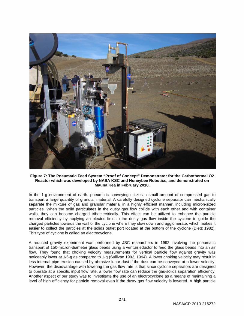
Figure 7: The Pneumatic Feed System “Proof of Concept” Demonstrator for the Carbothermal O2 Reactor which was developed by NASA KSC and Honeybee Robotics, and demonstrated on
Mauna Kea in February 2010. In the 1-g environment of earth, pneumatic conveying utilizes a small amount of compressed gas to transport a large quantity of granular material. A carefully designed cyclone separator can mechanically separate the mixture of gas and granular material in a highly efficient manner, including micron-sized particles. When the solid particulates in the dusty gas flow collide with each other and with container walls, they can become charged triboelectrically. This effect can be utilized to enhance the particle removal efficiency by applying an electric field to the dusty gas flow inside the cyclone to guide the charged particles towards the wall of the cyclone where they slow down and agglomerate, which makes it easier to collect the particles at the solids outlet port located at the bottom of the cyclone (Dietz 1982). This type of cyclone is called an electrocyclone. A reduced gravity experiment was performed by JSC researchers in 1992 involving the pneumatic transport of 150-micron-diameter glass beads using a venturi eductor to feed the glass beads into an air flow. They found that choking velocity measurements for vertical particle flow against gravity was noticeably lower at 1/6-g as compared to 1-g (Sullivan 1992, 1994). A lower choking velocity may result in less internal pipe erosion caused by abrasive lunar dust if the dust can be conveyed at a lower velocity. However, the disadvantage with lowering the gas flow rate is that since cyclone separators are designed to operate at a specific input flow rate, a lower flow rate can reduce the gas-solids separation efficiency. Another aspect of our study was to investigate the use of an electrocyclone as a means of maintaining a level of high efficiency for particle removal even if the dusty gas flow velocity is lowered. A high particle
NASA/CP-2010-216272

272
removal efficiency at the receiving end of the pneumatic transfer process is necessary in order to be able to recycle the convey gas for repeated use.
Figure 8: The exhaust from the cyclone separator in the foreground in the right figure was the input for an electro-cyclone (left figure) positioned behind it during the reduced gravity flight
pneumatic regolith transfer experiment conducted in August 2009. Reduced gravity flight experiment in Aug 2009, and cyclone separators for gas-solids filtration, including electro-
cyclone. The three main objectives of the terrestrial and reduced gravity flight (RGF) experiments were (1) to demonstrate the feasibility of pneumatically transferring lunar regolith as a dense, dusty gas to an ISRU reactor, (2) to measure our system’s typical mass transfer rate for a given lunar regolith simulant that is conveyed pneumatically against gravity as a dusty gas to a fixed vertical height under local gravity conditions (1-g and 1/6-g), and (3) to determine the efficiency of our series cyclone filtration system in removing particles from the exhaust gas flow, including the potential use of an electrocyclone to enhance particle removal efficiency. The configuration of the experiment is depicted below in Figure 9, and the specific details are as follows:
• The experiment assembly in Figure 9 consists of a polycarbonate secondary containment box with a secondary High Efficiency Particulate Arresting (HEPA) filter, supply and discharge containers for lunar regolith simulant, an eductor for pneumatic conveying, a convey pipe, two cyclone separators connected in series with HEPA filters on the exhaust of the final cyclone, air pressure and flow rate meters, and dust particle counters connected to the dusty gas inlet and the clean gas outlet of the second cyclone. Optional is a high voltage power supply that allows the second cyclone B to act as an electrocyclone if desired.
• Two lunar regolith simulants, known as NU-LHT-2M and Tephra, were studied. One simulant at a
time was contained within the experiment assembly shown in Fig. 9. The NU-LHT-2M lunar regolith simulant is based on the chemical composition of NASA averaged Apollo 16 regolith samples. Tephra is a volcanic ash and cinder material from Mauna Kea, Hawaii.
Figure 9 is a schematic of the experiment hardware contained within an aluminum framed housing, and enclosed by sheets of transparent polycarbonate around the sides and by sheets of aluminum at the top and at the base. The housing structure was designed to allow the pneumatic regolith transfer experiment to fly in a safely contained manner onboard an aircraft which conducted a series of parabolic flight paths. During each parabola, the RGF experiment was performed for 25 seconds under simulated lunar gravity conditions after which time the air flow was shut off during a period of time in which the experiment experienced variable gravity conditions including increased gravity. The use of HEPA filters ensured that
NASA/CP-2010-216272

273
particles larger than 0.3 micron would not exit into the ambient atmosphere outside of the pneumatic conveyor system. The polycarbonate sheets allowed for the pneumatic regolith transfer to be visible outside of the box, and also served as a secondary containment in case of dust leakage from the system. A secondary HEPA filter was mounted on the secondary containment box to prevent the filtered air from pressurizing the box. Compressed dry air was used as the convey gas so that the exhaust gas from the cyclones did not have to be vented outside of the aircraft.
Figure 9. Graphic of the reduced gravity (1/6-g) experiment hardware including a close-up view (right-side graphic) of a series array of cyclones with the upper most having a HEPA filter
attached to its exhaust gas outlet. The same setup was also used for ground tests at 1-g. (1) Two cyclone array using a mechanical cyclone (A) and an electrocyclone (B); (2) SS pipe; (3) Interface panel for gas inlet and gauges; (4) Regolith supply container and venturi eductor; (5) HEPA filter on the secondary containment box (7); (6) Regolith discharge container representing an ISRU
reactor mockup; and (7) Secondary containment box using aluminum frame and supports, and polycarbonate sheets. Total mass of the flight rig including lunar regolith simulant: 195 kg.
The regolith supply container (transparent acrylic) in Fig. 9 could be filled with 16.5 kg of lunar regolith simulant that was to be transferred to the regolith discharge container (also transparent acrylic), which served as a mockup of an ISRU reactor chamber. Height restrictions onboard the RGF aircraft limited the total transfer height to 1.5 m for conveying the lunar simulants from the bottom of the regolith supply container to the inlet of the first cyclone located above the regolith discharge container. The gas/solids mixer shown in Fig. 10 is a stainless steel venturi eductor. The eductor pulls granular material out from the center of the bottom plate of the regolith supply container, and it is used to entrain the lunar regolith simulant into the air flow and to convey the dusty gas along a stainless steel pipe to the cyclone separators. The cyclone body and air exhaust pipe of the two cyclones shown in Fig. 8 were fabricated from stainless steel, and they were joined using a non-metallic cap to electrically insulate the exhaust pipe from the cyclone body when the cyclone (B) is operated as an electrocyclone. Except for the air exhaust pipe of the electrocyclone, which is connected to the high voltage output cable of a high voltage DC power
NASA/CP-2010-216272

274
supply, the cyclone body and all other metal components contained within the secondary containment box are connected to the electrical ground.
Figure 10: An eductor produces a dense flow of dusty gas by creating a partial vacuum via the Venturi effect that entrains lunar regolith feedstock material into a flow of clean dry air.
Figure 11 shows the actual testing of the pneumatic transfer hardware during the reduced gravity flight as Tephra was transferred pneumatically into the Regolith Discharge Container, which served as an ISRU reactor mockup. Although nearly all of the Tephra was transferred during the reduced gravity flight, dust adherence to the walls of the acrylic container prevented an exact determination of the total time needed to complete the pneumatic transfer of Tephra into the discharge container. The same hardware setup was used to conduct the terrestrial testing discussed next. The RGF results are discussed later in further detail.
Figure 11: Photo of the RGF experiment showing Tephra that fell from cyclone A into the Regolith Discharge Container. The Tephra flowed vertically upward along a convey pipe from the eductor
located at the bottom of the Supply Container (not visible in photo). The convey pipe had a vertical-to-horizontal transition which connected it to the inlet of cyclone A in Fig. 9. The gas
exhaust from cyclone A became the input for the smaller cyclone B, which discharged dust into the blue hose shown in the picture. The exhaust from cyclone B passed through HEPA filter bags
before exiting into the transparent containment box, which had a secondary HEPA filter that allowed the filtered air to enter into the aircraft cabin.
NASA/CP-2010-216272

275
Terrestrial Experiments When compressed dry air was applied to the gas inlet of the venturi eductor, the partial vacuum created by the eductor was found to immediately begin feeding lunar regolith simulant material into the input air flow to the eductor, thus producing a very dense flow of dusty air that exited the eductor along the convey pipe towards the cyclone separators. Tephra, being less dense than NU-LHT-2M and having a different particle size distribution, was found to be relatively easier to convey pneumatically than NU-LHT-2M. Although, the supply container had a flat bottom rather than a funnel shape in order to reduce the overall height of the container, each simulant material was successfully educted from the center of the supply container’s base plate. The total amount of material that was transferred from the regolith supply container depended on the magnitude of the air pressure applied to the gas inlet of the eductor, and on the efficiency by which the regolith simulant could be fluidized within the container before being drawn out by the eductor. The dusty air flow that was produced at the eductor traveled a vertical height of 1.5 m before entering the first cyclone. Most of the granular material collected by the first cyclone exited the solids outlet port at the bottom of the cyclone to be deposited into the regolith discharge container. The dusty exhaust gas that exits from the top of any cyclone contains fine particles having sizes typically no larger than nine times the cut diameter of the cyclone. However, the actual size distribution of the particles contained in the flow between our two series cyclones could not be determined without disturbing the dynamics of the dusty air flow. The exhaust gas from the first cyclone became the input dusty gas flow for the smaller second cyclone, which was designed to have a cut diameter of a one micron or less. However, due to the very dense flow of dusty air (also observed in 1/6-g) entering the second cyclone, it was not possible to operate the second cyclone as an electrocyclone, which only performs effectively on a dilute particle input flow that was not able to be achieved using only two cyclones separators connected in series. Since the regolith feed to the eductor was not being metered during the terrestrial and reduced gravity tests, the continuous dense flow of dusty air overwhelmed the cyclones. The supply container would typically be filled with 15 – 17 kg of lunar regolith simulant. Each of the lunar regolith simulants, NU-LHT-2M and Tephra, was able to be pneumatically transferred from the center of a flat-bottom regolith supply container. With some fluidization of the simulant in the supply container, it was possible to transfer all but ~1 kg of simulant to the discharge container, which served as a mockup of an ISRU reactor chamber. Depending on the effectiveness of the fluidization of the granular material inside the supply container, typical mass transfer rates of 2 – 4 kg/min were achievable with an unmetered regolith feed to the eductor. Although metering the feed of regolith to the eductor would reduce the mass transfer rate and lengthen the overall transfer time, this would likely result in an improved performance of the cyclone separators in removing particles from the dusty air flow and depositing these particles into the regolith discharge container. These tradeoffs must be considered in designing a pneumatic regolith transfer system for lunar operations. Reduced Gravity Experiments A flight rig was constructed at NASA Kennedy Space Center to meet the safety requirements for conducting reduced gravity (1/6-g) tests onboard an aircraft. The aircraft achieves short periods of reduced gravity by flying a series of parabolic flight trajectories. During the parabolic trajectory, the aircraft also experiences periods of increased gravity (~1.8 g) which the experiment must also endure. The RGF pneumatic transfer experiment was initiated immediately after the lunar gravity condition was achieved and was terminated approximately 25 sec later at the end of the reduced gravity experience. Figure 11 shows the pneumatic transfer of Tephra under simulated lunar gravity conditions. As in the terrestrial tests, it was observed that most of the Tephra transferred from the supply container to the discharge container located beneath the cyclone, but the dense flow overwhelmed the cyclone separators. Insufficient visibility through the secondary containment box prevented the precise determination of the number of parabolas required to transfer the Tephra under 1/6-g conditions. Although the mass transfer rate of Tephra could not be determined, it was observed that approximately
NASA/CP-2010-216272

276
15 kg of Tephra was easily transferred pneumatically from the supply container in less than the ~15 minute duration in simulated lunar gravity. When the NU-LHT-2M transfer process began under 1/6-g conditions, this granular material was also transferred easily from the supply container to the discharge container despite being more compactable than Tephra. However, after ten parabolas (~250 sec), it was observed that the transfer process had stopped. Although the NU-LHT-2M was assumed to have been sieved, a post analysis showed that a ~0.5-cm-diameter “rock” had become clogged in the eductor’s solids inlet which prevented regolith simulant particles from entering the eductor and being entrained in the air flow. Nevertheless, it was observed that 8.8 kg of NU-LHT-2M could be transferred vertically resulting in a mass transfer rate of 2.1 kg/min. The Tephra mass transfer rate is believed to be probably greater than this value given that Tephra is less dense than NU-LHT-2M. The efficiency of our particular series cyclone filtration system in separating particles, including the use of an electrocyclone, could not be determined due to the dense flow of dusty air having overwhelmed the cyclones in 1-g and in the 1/6-g environment. The dense flow must be factored into a re-design of the cyclone system and 1/6-g effects must be included in the design parameters. It is likely that different cyclone systems will be required for the terrestrial 1-g system and for the lunar 1/6-g system due to the expected higher mass transfer rate of regolith in 1/6-g (Sullivan 1992, 1994). A pneumatic alternative to the venturi eductor for transferring regolith is to use the jet-lift method, which was successfully demonstrated at low pressure (Zacny). The jet-lift method selectively excites particles through transfer of gas momentum into the particles in the vicinity of a gas injection head. The resulting dusty gas flow is subsequently transported along a tube containing the particles as the gas attempts to ultimately escape into a low pressure environment. Experimental tests in a vacuum chamber at ~5 torr demonstrated regolith-mass-to-gas-mass transport efficiencies exceeding 1000:1 utilizing this technique.
Figure 12: Jet-Lift Regolith Transfer method.
Finally, the compressor requirements for pneumatic regolith transfer are 5 SCFC at 20 psi (138 kPa) of gaseous hydrogen. Since the temperature of the regolith transferred is approximately 700 degrees Celsius, compressors that meet these requirements are highly specialized and few vendors are capable or willing to tackle this challenge. Consequently, the search is continuing for a compressor that is suited to the special conditions imposed on the pneumatic regolith feed system by the ISRU reactor’s working environment.
NASA/CP-2010-216272

277
Conclusions The OPTIMA tests on Mauna Kea, Hawaii in November of 2008 demonstrated the feasibility of producing oxygen at rates equivalent to 660 kg/year in a Lunar Outpost. The enclosed auger regolith feed system performed well and met all objectives. Batches of 8 kg of tephra were consistently, repeatably and successfully fed from the input hopper to the reactor and then expelled to the surface. High temperatures and abrasive particles were handled well with this system. Lifetime testing is required to determine the wear rates and ultimate system reliability. The system proved to be very robust in limited field testing. Phase II of the ROxygen system design will incorporate the lessons learned and increase the fidelity of the prototype hardware. As a result of terrestrial and reduced gravity experiments, we have been able to show that the dense-flow pneumatic transfer method is able to successfully convey lunar regolith simulants such as NU-LHT-2M and Tephra to a vertical height of 5 ft (1.5 m), which is not an absolute physical limit but simply a limitation that was imposed by the available vertical space in the reduced gravity aircraft. Although we have shown that it is possible to transfer lunar regolith simulants pneumatically as a dense flow of dusty gas in a simulated lunar gravity environment, it is also important to realize that the reduced gravity aircraft also undergoes periods of increased gravity as high as 1.8 g, which may cause the granular regolith simulant material to become compacted. The degree to which this effect might influence the pneumatic regolith transfer process can be lessened by keeping the simulant in a semi-fluidized state throughout the parabolic flight. A cyclone separator is an important component of a pneumatic regolith transfer system delivers the regolith to a desired location, and filters the convey gas sufficiently so that the gas can be reused. It may be possible to design a single cyclone to perform gas-solids separation provided that a moderate dense flow of dusty gas is able to yield a sufficient mass transfer rate by metering the regolith feed at the eductor. The exhaust gas from any cyclone separator will contain fine particles that may be detrimental to the mechanical operation of a compressor intended for reusing the gas. In that case, a second cyclone, known as an electrocyclone, may be designed to remove particles that are even smaller than those removed by an ordinary cyclone of the same size. Overall, the reduced gravity flight experiment and field testing proved that lunar regolith simulant can be effectively conveyed pneumatically in an ISRU oxygen production plant in order to introduce regolith simulant into the reactor; fluidize it within the reactor and hopper feed systems; transfer it from outer reactor annulus zones to an inner reactor cylinder vessel; and subsequently expel it from the reactor for disposal or use in subsequent resource processing (silica, aluminum, titanium, iron, etc.). The results of this experiment were used to influence the design of the ROxygen second generation oxygen production system being developed by the NASA ISRU project, in order to show that it is indeed possible to produce a minimum rate of one metric ton of oxygen per year (of lunar operation) from lunar regolith simulants in a reliable, long life and low maintenance system.
Acknowledgements
The NASA RFS team would like to acknowledge the support of the ETDP, CxP Lunar Surface Systems Office and the ISRU project for funding and directing technology development and systems integration work. In particular we would like to thank the ISRU project manager: Mr. William Larson, the deputy ISRU project manager: Mr. Gerald Sanders, the Director of the Innovative Partnerships Program (IPP), Mr. Douglas Comstock, and the Chief of the Lunar Surface Systems (LSS) Office, Mr. Christopher Culbert. The reduced gravity experiment was supported by the NASA IPP under a 2009 program known as Facilitated Access to the Space Environment for Technology Development and Training (FAST). NASA IPP also supported the Pacific International Space Center for Exploration Studies PISCES) analog field tests on Mauna Kea Hawaii in November 2008, as well as the Carbothermal pneumatic feed system attachment that will be tested in January 2010 at the PISCES test site, Mauna Kea, Hawaii.
NASA/CP-2010-216272

278
Outstanding assistance from the Reduced Gravity Office at NASA Johnson Space Center ensured that the experiment would fly safely. The NASA KSC Prototype Development Laboratory contributed substantial manufacturing expertise and effort in order to produce this experimental payload under tight schedule constraints. Ground-based tests at NASA Kennedy Space Center were supported through funding from the NASA KSC CDDF program and from the ROxygen ISRU project under NASA ETDP. Finally, the management of the NASA KSC Surface Systems Office and KSC Engineering and Technology Directorates were very supportive of this advanced technology development effort. In addition all of our industrial partners mentioned in the paper above, as well as component suppliers that have often provided invaluable advice and support. Most of all the team of dedicated engineers and technicians must be thanked for their commitment and hard work in order to design, fabricate and test these ISRU systems, often in harsh and demanding field test analog site locations with dust storms, extreme temperatures and long test days.
References Caruso, J.J., Greer, Lawrence C.; John, Wentworth T.; Spina, Dan C.; Krasowski, Mike J.; Abel, Phillip B.; Prokop, Norman F.; Flatico, Joseph M.; Sacksteder, Kurt R.,”Cratos: A Simple Low Power Excavation and Hauling System for Lunar Oxygen Production and General Excavation Tasks,” PTMSS Conference, Sudbury, Ontario, Canada, 10-13 Jun. 2007 Cooke, D. et al, Exploration Strategy and Architecture, Implementing the Vision, 2nd Space Exploration Conference, AIAA, Houston (2006). Crosby, Kevin M., Agui, Juan, Pennington, C., Sorenson, E., Martin, E., Fritz, I., and Frye, B. (2008). “Inertial Filtration of Lunar Dust in Reduced Gravity,” LPI Contribution No. 1446, p. 43, presented at the Joint Annual Meeting of LEAG-ICEUM-SRR, 28-31 October 2008, Cape Canaveral, Florida. Culbert, Chris (2009). “Lunar Surface Systems Project Overview.” NASA,http://www.nasa.gov/exploration/library/lss_systems_concepts_workshop.html. Dhodapkar, Shrikant, Jacob, K., and Hu, S. (2006). “Fluid-Solid Transport in Ducts,” in “Multiphase Flow Handbook,” ed. Clayton T. Crowe, Taylor & Francis, Boca Raton, Florida. Dietz, P.W. (1982). “Electrostatically Enhanced Cyclone Separators,” Powder Technology 31, 221-226. Liu, Henry, and Marrero, T.R. (1988). “Transportation by Pipelines in Space Colonies,” in “Engineering, construction, and operations in space”, Proceedings of Space 88, Eds. Johnson, S.W., and Wetzel, J.P., 29-31 August 1988, Albuquerque, New Mexico. Mills, David, Jones, M.G., and Agarwal, V.K. (2004). “Handbook of Pneumatic Conveying Engineering.” Marcel-Decker, New York. Pell, Mel, Dunson, J.B., and Knowlton, T.M. (2008). “Gas-Solid Operations and Equipment,” Ch. 17 in “Perry's Chemical Engineers' Handbook” (8th Edition), eds. Green, Don W. and Perry, Robert H., McGraw-Hill, New York. Sanders, G.; Larson, W., “NASA In-Situ Resource Utilization (ISRU) Development & Field Testing,” Presentation to “ Hawaii’s Aerospace Industry: The Next Frontier”, Honolulu, The Hawaii State Capital Auditorium, August 21, 2008 Schrunk, David G., Sharpe, B.L., Cooper, B.L., and Thangavelu, M. (1999). “The Moon: Resources, Future Development and Colonization,” Wiley-Praxis, New York. Sullivan, Thomas A., Koenig, E., Knudsen, C.W., and Gibson, M.A. (1992). “Pneumatic Conveying of Materials at Partial Gravity,” AIAA 92-1667, presented at the AIAA Space Prog. and Tech. Conf., 24-27 March 1992, Huntsville, Alabama. Sullivan, Thomas A., Koenig, E., Knudsen, C.W., and Gibson, M.A. (1994). “Pneumatic Conveying of Materials at Partial Gravity,” J. Aerosp. Eng. 7(2), 199-208. Zacny, Kris A., Mungas, Greg, Mungas, Chris, Fisher, Dave, and Hedlund, Magnus. “Pneumatic Excavator and Regolith Transport System for Lunar ISRU and Construction”, Paper #AIAA 2008-7824, AIAA SPACE 2008 Conference & Exposition, 9 - 11 September 2008, San Diego, California.
NASA/CP-2010-216272