Performance of Linear Motor Type Rail Brake Using Roller ...
5
41 41 41 41 41 QR of RTRI, Vol. 53, No. 1, Feb. 2012 PAPER PAPER PAPER PAPER PAPER Performance of Linear Motor T Performance of Linear Motor T Performance of Linear Motor T Performance of Linear Motor T Performance of Linear Motor Type Rail Brake Using Roller Rig T ype Rail Brake Using Roller Rig T ype Rail Brake Using Roller Rig T ype Rail Brake Using Roller Rig T ype Rail Brake Using Roller Rig Test Bench est Bench est Bench est Bench est Bench 1. Introduction 1. Introduction 1. Introduction 1. Introduction 1. Introduction An intrinsic feature of eddy current rail brakes is that they guarantee a stable braking force unaffected by rail tread surface conditions, since they function with- out making contact with the rails. Application of such braking systems however gives rise to certain problems such as rail heating and difficulty in guaranteeing a power supply to energize the brake in the case of failure of the main train circuit. For these reasons, the system has not yet been commercialized in Japan [1]. A goal was therefore set to solve the problems related to use of eddy current rail brake systems, by applying linear mo- tor technology [2, 3]. The proposed LIM-type rail brake includes an arma- ture of linear induction motors (LIMs) instead of the DC- excitation-pole of the conventional system. The proposed rail brake generates braking forces by dynamic braking operation. This brake offers advantages, as illustrated in Fig. 1. (1) For the same braking force, the increase in rail temperature in the case of the LIM-type rail brake is considerably less than that in the case of a conventional DC-type eddy current brake. (2) The power required for excitation is obtained from the kinetic energy of the vehicle. This paper describes the experimental verifications of the LIM-type rail brake system, which includes the armature and excitation system driven by “dynamic brak- ing with zero electrical output.” In order to generate power and maximize the brak- ing force density despite the limited installation room on the bogie, studies were made to find a suitable design for the armature of LIM-type rail brake. To validate the proposed design, a prototype armature was constructed and its electromagnetic characteristics were examined on a test bench with a roller rig. The excitation system for LIM-type rail brake relies on the brake being able to be energized without using excitation power sources such as a feeder circuit and an onboard main circuit. Such high reliability can be achieved by providing an inde- pendent excitation system. To examine the feasibility of this excitation method, am excitation control method was investigated after which verification tests were per- formed using an excitation system with the abovementioned prototype armature. The results dem- onstrated that the LIM-type rail brake can generate braking forces which meet the set target values and can be energized without using an external power source. Yasuaki SAKAMOTO, Ph.D. asuaki SAKAMOTO, Ph.D. asuaki SAKAMOTO, Ph.D. asuaki SAKAMOTO, Ph.D. asuaki SAKAMOTO, Ph.D. Assistant Senior Researcher, Takayuki KASHIW akayuki KASHIW akayuki KASHIW akayuki KASHIW akayuki KASHIWAGI AGI AGI AGI AGI Assistant Senior Researcher, Hitoshi HASEGA Hitoshi HASEGA Hitoshi HASEGA Hitoshi HASEGA Hitoshi HASEGAWA, Ph.D. A, Ph.D. A, Ph.D. A, Ph.D. A, Ph.D. Laboratory Head, Electromagnetic Applications Laboratory, Maglev Systems Technology Division Takashi SASAKA akashi SASAKA akashi SASAKA akashi SASAKA akashi SASAKAWA, Ph.D. A, Ph.D. A, Ph.D. A, Ph.D. A, Ph.D. Administration Division Yasushi KARINO asushi KARINO asushi KARINO asushi KARINO asushi KARINO Senior Researcher, Brake Control Laboratory, Vehicle Control Technology Division Studies have been carried out on a rail brake applying linear induction motor technol- ogy, called LIM-type rail brake. This brake is capable of generating braking forces with- out contact. In addition, this method decreases the rise in rail temperature, and no on- board supply is required by using dynamic braking. It is necessary however to install this brake between front and rear wheels of the bogie. A prototype rail brake system was de- signed and built and its electromagnetic characteristics were examined on a test bench with a roller rig. These investigations revealed that the LIM-type rail brake could be ap- plicable for practical use. Keywords Keywords Keywords Keywords Keywords: rail brake, eddy current brake, linear induction motor, dynamic braking, rail heating Fig. 1 Energy input and output in rail braking Fig. 1 Energy input and output in rail braking Fig. 1 Energy input and output in rail braking Fig. 1 Energy input and output in rail braking Fig. 1 Energy input and output in rail braking Kinetic energy DC-type rail brake LIM-type rail brake Braking Rail heat generation Rail heat generation Excitation power Regenerative power Excitation power
Transcript of Performance of Linear Motor Type Rail Brake Using Roller ...
4141414141QR of RTRI, Vol. 53, No. 1, Feb. 2012
PAPERPAPERPAPERPAPERPAPER
Performance of Linear Motor TPerformance of Linear Motor TPerformance of Linear Motor TPerformance of Linear Motor TPerformance of Linear Motor Type Rail Brake Using Roller Rig Type Rail Brake Using Roller Rig Type Rail Brake Using Roller Rig Type Rail Brake Using Roller Rig Type Rail Brake Using Roller Rig Test Benchest Benchest Benchest Benchest Bench
1. Introduction1. Introduction1. Introduction1. Introduction1. Introduction
An intrinsic feature of eddy current rail brakes isthat they guarantee a stable braking force unaffectedby rail tread surface conditions, since they function with-out making contact with the rails. Application of suchbraking systems however gives rise to certain problemssuch as rail heating and difficulty in guaranteeing apower supply to energize the brake in the case of failureof the main train circuit. For these reasons, the systemhas not yet been commercialized in Japan [1]. A goalwas therefore set to solve the problems related to use ofeddy current rail brake systems, by applying linear mo-tor technology [2, 3].
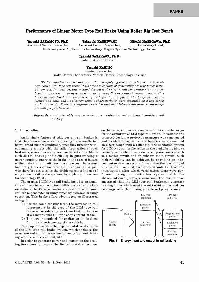
The proposed LIM-type rail brake includes an arma-ture of linear induction motors (LIMs) instead of the DC-excitation-pole of the conventional system. The proposedrail brake generates braking forces by dynamic brakingoperation. This brake offers advantages, as illustratedin Fig. 1.
(1) For the same braking force, the increase in railtemperature in the case of the LIM-type railbrake is considerably less than that in the caseof a conventional DC-type eddy current brake.
(2) The power required for excitation is obtainedfrom the kinetic energy of the vehicle.
This paper describes the experimental verificationsof the LIM-type rail brake system, which includes thearmature and excitation system driven by “dynamic brak-ing with zero electrical output.”
In order to generate power and maximize the brak-ing force density despite the limited installation room
on the bogie, studies were made to find a suitable designfor the armature of LIM-type rail brake. To validate theproposed design, a prototype armature was constructedand its electromagnetic characteristics were examinedon a test bench with a roller rig. The excitation systemfor LIM-type rail brake relies on the brake being able tobe energized without using excitation power sources suchas a feeder circuit and an onboard main circuit. Suchhigh reliability can be achieved by providing an inde-pendent excitation system. To examine the feasibility ofthis excitation method, am excitation control method wasinvestigated after which verification tests were per-formed using an excitation system with theabovementioned prototype armature. The results dem-onstrated that the LIM-type rail brake can generatebraking forces which meet the set target values and canbe energized without using an external power source.
YYYYYasuaki SAKAMOTO, Ph.D.asuaki SAKAMOTO, Ph.D.asuaki SAKAMOTO, Ph.D.asuaki SAKAMOTO, Ph.D.asuaki SAKAMOTO, Ph.D.Assistant Senior Researcher,
TTTTTakayuki KASHIWakayuki KASHIWakayuki KASHIWakayuki KASHIWakayuki KASHIWAGIAGIAGIAGIAGIAssistant Senior Researcher,
Hitoshi HASEGAHitoshi HASEGAHitoshi HASEGAHitoshi HASEGAHitoshi HASEGAWWWWWA, Ph.D.A, Ph.D.A, Ph.D.A, Ph.D.A, Ph.D.Laboratory Head,
Electromagnetic Applications Laboratory, Maglev Systems Technology Division
TTTTTakashi SASAKAakashi SASAKAakashi SASAKAakashi SASAKAakashi SASAKAWWWWWA, Ph.D.A, Ph.D.A, Ph.D.A, Ph.D.A, Ph.D.Administration Division
YYYYYasushi KARINOasushi KARINOasushi KARINOasushi KARINOasushi KARINOSenior Researcher,
Brake Control Laboratory, Vehicle Control Technology Division
Studies have been carried out on a rail brake applying linear induction motor technol-ogy, called LIM-type rail brake. This brake is capable of generating braking forces with-out contact. In addition, this method decreases the rise in rail temperature, and no on-board supply is required by using dynamic braking. It is necessary however to install thisbrake between front and rear wheels of the bogie. A prototype rail brake system was de-signed and built and its electromagnetic characteristics were examined on a test benchwith a roller rig. These investigations revealed that the LIM-type rail brake could be ap-plicable for practical use.
KeywordsKeywordsKeywordsKeywordsKeywords: rail brake, eddy current brake, linear induction motor, dynamic braking, railheating
Fig. 1 Energy input and output in rail brakingFig. 1 Energy input and output in rail brakingFig. 1 Energy input and output in rail brakingFig. 1 Energy input and output in rail brakingFig. 1 Energy input and output in rail braking
Kineticenergy
DC-typerail brake
LIM-typerail brake
Braking
Rail heatgeneration
Rail heatgeneration
Excitationpower
Regenerativepower
Excitationpower
4242424242 QR of RTRI, Vol. 53, No. 1, Feb. 2012
2. LIM-type rail brake2. LIM-type rail brake2. LIM-type rail brake2. LIM-type rail brake2. LIM-type rail brake
2.1 Composition2.1 Composition2.1 Composition2.1 Composition2.1 Composition
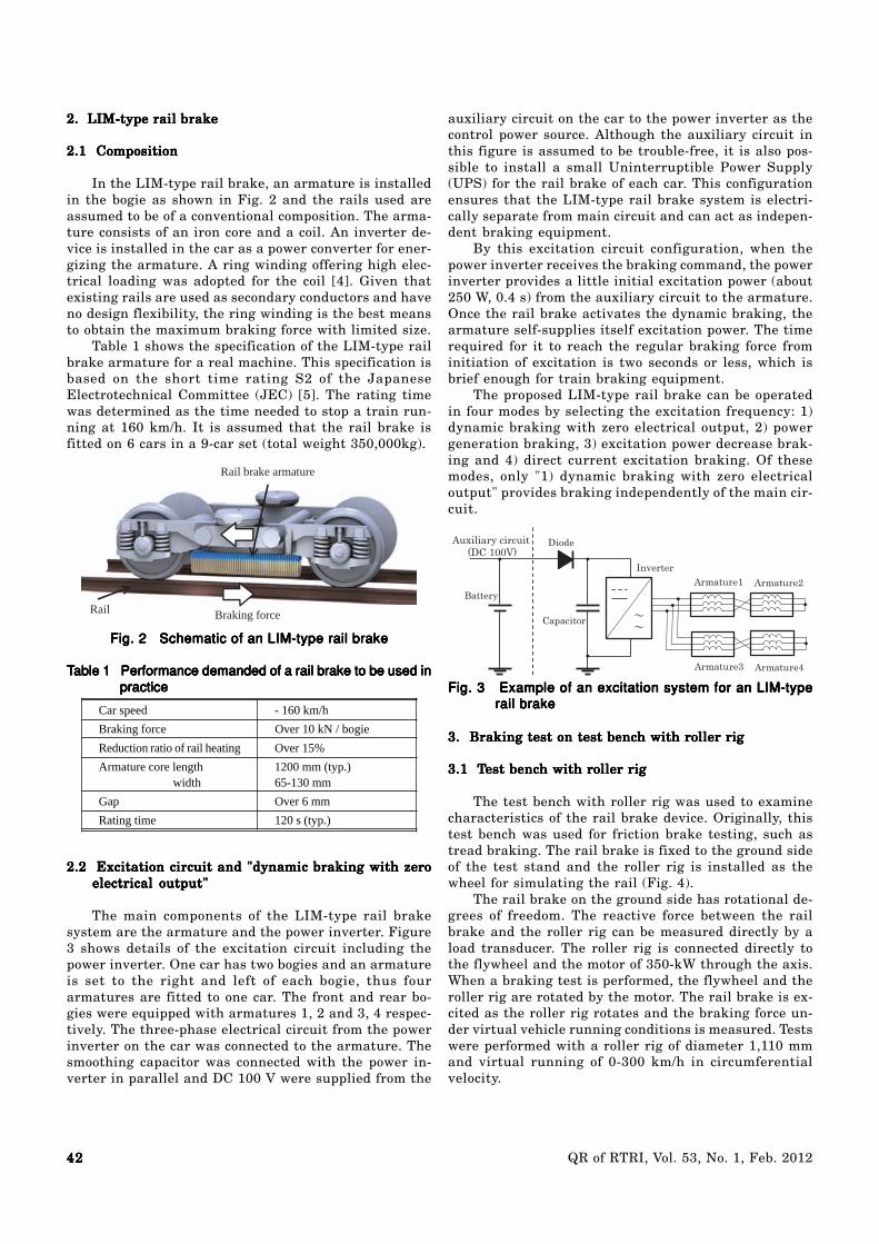
In the LIM-type rail brake, an armature is installedin the bogie as shown in Fig. 2 and the rails used areassumed to be of a conventional composition. The arma-ture consists of an iron core and a coil. An inverter de-vice is installed in the car as a power converter for ener-gizing the armature. A ring winding offering high elec-trical loading was adopted for the coil [4]. Given thatexisting rails are used as secondary conductors and haveno design flexibility, the ring winding is the best meansto obtain the maximum braking force with limited size.
Table 1 shows the specification of the LIM-type railbrake armature for a real machine. This specification isbased on the short time rating S2 of the JapaneseElectrotechnical Committee (JEC) [5]. The rating timewas determined as the time needed to stop a train run-ning at 160 km/h. It is assumed that the rail brake isfitted on 6 cars in a 9-car set (total weight 350,000kg).
TTTTTable 1 able 1 able 1 able 1 able 1 Performance demanded of a rail brake to be used inPerformance demanded of a rail brake to be used inPerformance demanded of a rail brake to be used inPerformance demanded of a rail brake to be used inPerformance demanded of a rail brake to be used inpracticepracticepracticepracticepractice
Fig. 2 Schematic of an LIM-type rail brakeFig. 2 Schematic of an LIM-type rail brakeFig. 2 Schematic of an LIM-type rail brakeFig. 2 Schematic of an LIM-type rail brakeFig. 2 Schematic of an LIM-type rail brake
Rail brake armature
Rail Braking force
Car speed - 160 km/h
Braking force Over 10 kN / bogie
Reduction ratio of rail heating Over 15%
Armature core length width
1200 mm (typ.)65-130 mm
Gap Over 6 mm
Rating time 120 s (typ.)
2.2 Excitation circuit and "dynamic braking with zero2.2 Excitation circuit and "dynamic braking with zero2.2 Excitation circuit and "dynamic braking with zero2.2 Excitation circuit and "dynamic braking with zero2.2 Excitation circuit and "dynamic braking with zeroelectrical output"electrical output"electrical output"electrical output"electrical output"
The main components of the LIM-type rail brakesystem are the armature and the power inverter. Figure3 shows details of the excitation circuit including thepower inverter. One car has two bogies and an armatureis set to the right and left of each bogie, thus fourarmatures are fitted to one car. The front and rear bo-gies were equipped with armatures 1, 2 and 3, 4 respec-tively. The three-phase electrical circuit from the powerinverter on the car was connected to the armature. Thesmoothing capacitor was connected with the power in-verter in parallel and DC 100 V were supplied from the
auxiliary circuit on the car to the power inverter as thecontrol power source. Although the auxiliary circuit inthis figure is assumed to be trouble-free, it is also pos-sible to install a small Uninterruptible Power Supply(UPS) for the rail brake of each car. This configurationensures that the LIM-type rail brake system is electri-cally separate from main circuit and can act as indepen-dent braking equipment.
By this excitation circuit configuration, when thepower inverter receives the braking command, the powerinverter provides a little initial excitation power (about250 W, 0.4 s) from the auxiliary circuit to the armature.Once the rail brake activates the dynamic braking, thearmature self-supplies itself excitation power. The timerequired for it to reach the regular braking force frominitiation of excitation is two seconds or less, which isbrief enough for train braking equipment.
The proposed LIM-type rail brake can be operatedin four modes by selecting the excitation frequency: 1)dynamic braking with zero electrical output, 2) powergeneration braking, 3) excitation power decrease brak-ing and 4) direct current excitation braking. Of thesemodes, only "1) dynamic braking with zero electricaloutput" provides braking independently of the main cir-cuit.
Fig. 3 Example of an excitation system for an LIM-typeFig. 3 Example of an excitation system for an LIM-typeFig. 3 Example of an excitation system for an LIM-typeFig. 3 Example of an excitation system for an LIM-typeFig. 3 Example of an excitation system for an LIM-typerail brakerail brakerail brakerail brakerail brake
Armature1 Armature2
Armature3 Armature4
Inverter
Capacitor
Battery
DiodeAuxiliary circuit (DC 100V)
3. Braking test on test bench with roller rig3. Braking test on test bench with roller rig3. Braking test on test bench with roller rig3. Braking test on test bench with roller rig3. Braking test on test bench with roller rig
3.1 T3.1 T3.1 T3.1 T3.1 Test bench with roller rigest bench with roller rigest bench with roller rigest bench with roller rigest bench with roller rig
The test bench with roller rig was used to examinecharacteristics of the rail brake device. Originally, thistest bench was used for friction brake testing, such astread braking. The rail brake is fixed to the ground sideof the test stand and the roller rig is installed as thewheel for simulating the rail (Fig. 4).
The rail brake on the ground side has rotational de-grees of freedom. The reactive force between the railbrake and the roller rig can be measured directly by aload transducer. The roller rig is connected directly tothe flywheel and the motor of 350-kW through the axis.When a braking test is performed, the flywheel and theroller rig are rotated by the motor. The rail brake is ex-cited as the roller rig rotates and the braking force un-der virtual vehicle running conditions is measured. Testswere performed with a roller rig of diameter 1,110 mmand virtual running of 0-300 km/h in circumferentialvelocity.

4343434343QR of RTRI, Vol. 53, No. 1, Feb. 2012
3.2 Rail brake armature prototype3.2 Rail brake armature prototype3.2 Rail brake armature prototype3.2 Rail brake armature prototype3.2 Rail brake armature prototype
The armature of the rail brake installed on the rollerrig test bench was curved in shape. Figure 5 is an exter-nal view of the test stand, Fig. 6 is a diagram of theconfiguration of the armature and Table 2 shows thearmature’s specifications.
The ring winding of the copper rectangular wire was
Fig. 4 TFig. 4 TFig. 4 TFig. 4 TFig. 4 Test bench with roller rigest bench with roller rigest bench with roller rigest bench with roller rigest bench with roller rig
Load transducer
Flywheel
Motor
Rail brake
Roller rig
Fig. 6 Configuration diagram of the armatureFig. 6 Configuration diagram of the armatureFig. 6 Configuration diagram of the armatureFig. 6 Configuration diagram of the armatureFig. 6 Configuration diagram of the armature
Fig. 5 External view of the test benchFig. 5 External view of the test benchFig. 5 External view of the test benchFig. 5 External view of the test benchFig. 5 External view of the test bench
268
95
238
6.5
65
983
r=563
(a) Longitudinal cross-section
(b) Transverse cross-section
Unit [mm]Coil
Roller rig
Core
Coil Core
Rail brake(Armature)
Roller rig
adapted to the basic armature configuration given the lim-ited space for brake systems on the bogie. The core length ofthe armature was one quarter of the circumference of theroller rig. The number of poles could be varied by changingthe connection of the coil terminals because the coil was aring winding. In this report, the four poles where the maxi-mum braking force could be performed are described.
When braking forces are generated, large normalforces are also generated between the roller rig and therail brake. The roller rig can only rotate around its axis;therefore, the gap length does not change under theseaccompanying normal forces. The test bench was alsoequipped with a load transducer, temperature sensors,ammeters and voltmeters.
3.3 Power inverter and controller3.3 Power inverter and controller3.3 Power inverter and controller3.3 Power inverter and controller3.3 Power inverter and controller
A specialized power inverter with a rating capacityof 90 kVA and rating voltage DC 600 V was used for the"dynamic braking with zero electrical output" brakingtests. A power source of with a rating output of 300 Wand rating voltage of DC 100 V was used as the abovementioned auxiliary circuit and was connected to thepower inverter through the diode. This power source wasutilized as both an initial excitation power source andcontrol power source for the inverter. The analog sig-nals of the frequency command and the output voltagecommand were output from the external controller. Thepower inverter received these signals and generated thePWM waveform voltage corresponding to the command.
TTTTTable able able able able 22222 Specification of the armatureSpecification of the armatureSpecification of the armatureSpecification of the armatureSpecification of the armature
Core LengthWidthHeight
983 mm95 mm150 mm
Slot NumberWidthDepthPitch
3614 mm79.5 mm25.5 mm
Coil Cross sectionTurns
2.6 * 12 mm28
Pole NumberPitch
4229.5 mm
Weight 278 kg
Gap 6.5 mm
Fig. 7 TFig. 7 TFig. 7 TFig. 7 TFig. 7 Test control system diagramest control system diagramest control system diagramest control system diagramest control system diagram
Brake commandExternal controller
Auxiliary circuit(DC 100V)
Inverter Armature
Iac
Vdc Idc
Vref*fref*

4444444444 QR of RTRI, Vol. 53, No. 1, Feb. 2012
The rated output current of the power inverter was 100A. Figure 7 shows the test control system diagram.
Excepting "dynamic braking with zero electrical out-put" test, the external controller is not needed and a gen-eral-purpose power inverter with an output current of morethan 350 A can be used for maximum braking force tests.
4. T4. T4. T4. T4. Test resultsest resultsest resultsest resultsest results
4.1 Braking force4.1 Braking force4.1 Braking force4.1 Braking force4.1 Braking force
Figure 8 shows the test results in which the brakingforce at each speed was measured on the test bench witha roller rig. The braking force of the rail brake achievedthe target braking force of 10 kN/bogie in the 50-300 km/h speed range. The threshold limit values of adhesive brak-ing force, generated by the wheel and rail are also shownin the figure. Braking force in adhesive braking decreasesas train speed increases, whereas with rail braking, itdoes not. This is a specificity and advantage of rail brak-ing. These tests confirmed that the braking force of therail brake achieved target values and demonstrated thehigher performance of non-adhesive braking over adhe-sive braking in the high-speed range.
Fig. 8 Braking forceFig. 8 Braking forceFig. 8 Braking forceFig. 8 Braking forceFig. 8 Braking force
00 50 100 150 200 250 300
Brak
ing
forc
e (k
N /
bogi
e)
Target values of rail brake
10
20
Velocity [km/h]
Measured values of rail brakeAdhesive brake
4.2 Brake control of "dynamic braking with zero4.2 Brake control of "dynamic braking with zero4.2 Brake control of "dynamic braking with zero4.2 Brake control of "dynamic braking with zero4.2 Brake control of "dynamic braking with zeroelectrical output"electrical output"electrical output"electrical output"electrical output"
Figure 9 shows the start-up control test of "dynamicbraking with zero electrical output" in which the rollerrig was rotated at simulated speed of 160 km/h. Arma-ture current was increased in line with the brake com-mand and a braking force was generated. The brakingforce stabilization time was approximately 1.4 s and sat-isfying the required specification. The DC voltage wasalso increased satisfactorily. A stable control of "dynamicbraking with zero electrical output" was achieved. Inaddition, the electric power of the auxiliary circuit wasmeasured under various conditions so that the first mo-mentary control power for the start-up was 50-250 Wand 0.2-0.4 s. This level of electric power is within therange which can be covered with an auxiliary circuit ora small storage battery.
The inertia moment of the flywheel connected di-rectly with the roller rig was set to the value correspond-ing to the inertial mass of the railway vehicle. The re-sult of the "dynamic braking with zero electrical out-
put" brake control test by is shown in Fig. 10. The iner-tial moment of the flywheel was set to be 969 kgm2 simu-lating the 40,000 kg of a vehicle’s inert mass equippedwith four rail brake armatures. The roller rig was ro-tated to simulate a speed of 160 km/h. Within one secondfrom commencement of free-running, a brake command of100 A in current was applied to the external controller andthe rail brake. In this brake control test, a constant decel-eration was performed with stable values of output cur-rent at 100 A, braking force 1.5 kN and DC voltage 600 V.With regard to the braking force of this rail brake, therewas a gradual peak at around 100 km/h and the brakingforce slightly increased with deceleration. When the simu-lated speed of the roller rig fell to under 50 km/h, the brakecontrol stopped by virtue of the decrease in the DC voltagebecause power available was insufficient. Under real con-ditions, a vehicle would be decelerated at this speed witha mechanical brake such as a tread brake after the railbrake control stopped.
In this brake control test, the external controller wasoperated only by the control values corresponding to the
Fig. 10 Braking control test for "dynamic braking withFig. 10 Braking control test for "dynamic braking withFig. 10 Braking control test for "dynamic braking withFig. 10 Braking control test for "dynamic braking withFig. 10 Braking control test for "dynamic braking withzero electrical output"rtzero electrical output"rtzero electrical output"rtzero electrical output"rtzero electrical output"rt
Fig. 9 Start-up control testFig. 9 Start-up control testFig. 9 Start-up control testFig. 9 Start-up control testFig. 9 Start-up control test
Time [s]
Brak
ing
forc
e (k
N)
Velo
city
(km
/h)
Curr
ent (
A)Vo
ltage
(V)
Volta
ge (V
)
Freq
uenc
y (H
z)Velocity vControl current I* Output current I
Output voltage Vref*Braking force Fb
DC Voltage Vdc Frequency Fref*
0
0.5
1
1.5
2
0
50
100
150
200
0 5 10 15 20
Brak
ing
forc
e[kN
], D
C Vo
ltage
[kV]
Velo
city
[km
/h],
Curr
ent[A
]
Time[s]
Start up Generating braking force
Velocity
Current
Brakecommand
DC voltage
Braking force

4545454545QR of RTRI, Vol. 53, No. 1, Feb. 2012
impedance of the armature at the simulated speed of 160km/h, without certain types of information such as sensedspeed. Tests therefore confirmed that the control systemusing "dynamic braking with zero electrical output with-out speed sensor" could be achieved.
4.3 Reduced rail heating4.3 Reduced rail heating4.3 Reduced rail heating4.3 Reduced rail heating4.3 Reduced rail heating
Rail heating was estimated from the temperature riseof the roller rig in the braking tests. The inertial mo-ment of the flywheel was set to an equivalent value of40,000 kg of inert vehicle mass with four rail brakearmatures. The temperature rises in the roller rig dur-ing deceleration produced by rail braking at simulatedspeeds of 65-30 km/h were measured. Figure 11 showsthe maximum temperature rise during roller rig decel-eration under the same average braking force with dif-ferent excitation frequencies. Since the roller rig not thesame as an actual rail and the same longitudinal sec-tion is heated repeatedly during braking tests, the testspeed was limited. For the same reasons, absolute tem-perature rise values were not same as would be with anactual rail. The authors therefore evaluated the rail tem-perature rise through relative values based on the DCexcitation modes for which temperature rises were thegreatest. In these tests, because of the power inverterlimitations, the direct current excitation was substitutedby 1 Hz alternate current excitation called “DC excita-tion mode.”
Figure 11 shows confirmation that the temperaturerise of the roller rig is actually curtailed under dynamicbraking. "Dynamic braking with zero electrical output"regulates the low frequency to balance the generatedpower and the armature copper losses. On the otherhand, in case of the active dynamic braking, this type ofrail braking helps to decrease roller rig temperature byabout 50%. This confirms that LIM-type rail braking iseffective in reducing rail heating.
type rail brake, which resolves the problems found in con-ventional rail braking. This rail brake can reduce the risein rail temperature rise by adjusting the frequency of thecurrent to the armature. By using small an electricalpower source to start braking, the rail brake generatesthe subsequent required power itself by virtue of dynamicbraking and so no power source is needed to actually op-erate the rail brake. These methods overcome the prob-lems caused by traditional rail braking.
The authors manufactured a full-scale rail brakeprototype. Ring-winding was adopted in the armatureused for investigations to attain the maximum brakingforce within a limited space. This rail brake prototypewas tested with simulated running speeds up to a maxi-mum of 300 km/h on a test bench with roller rig. Thefollowing results were obtained:
(1) It is proven that the target braking force of 10kN/bogie can be generated at a simulated runningspeed of 50-300 km/h.
(2) It is confirmed that the predetermined brakingforce is reached within two seconds, using onlythe auxiliary circuit.
(3) By using “dynamic braking with zero electricaloutput,” the rail brake maintains a braking forcewithin running speed range of 300-50 km/h, with-out either information from outside the invertersuch as from speed sensors or the power supplyfrom the main circuit.
(4) It is confirmed that rail heating is reduced by aratio of 50% or more according to the tempera-ture measurements taken on the roller rig whileusing the LIM-type rail brake.
The authors shall develop a "LIM-type rail brake"for application to a real bogie, based on the results oftests performed on the braking test bench with rollerrig.
ReferencesReferencesReferencesReferencesReferences
[1] Obara, T., et al., “An Emergency Brake System forConventional Lines,” Proceedings of the InternationalSymposium on Railroad Cybernetics, pp. 252−256, 1991(in Japanese).
[2] Sakamoto, Y., et al., “Linear eddy current brake forrailway vehicles using dynamic braking,” in 2008International Conference on Electrical Machines,Vilamoura, Portugal, September 6−9, 2008, Paper1083.
[3] Sakamoto, Y., et al., “Rail Brake System using a Lin-ear Induction Motor for Dynamic Braking,” IEEJTrans. IA, Vol. 129, No.3, pp. 342−349, 2009 (in Japa-nese).
[4] Sakamoto, Y., et al., “A study on the design of thearmature of a linear rail brake,” The Papers of Techni-cal Meeting on Linear Drives, IEE Japan, LD-08-83,2008 (in Japanese).
[5] Japanese Electrotechnical Committee of IEE Japan,Standard of the Japanese Electrotechnical Commit-tee JEC-2137 Induction Motor, Denkishoin, 2000 (inJapanese).
Fig. 1Fig. 1Fig. 1Fig. 1Fig. 11 Roller rig temperature1 Roller rig temperature1 Roller rig temperature1 Roller rig temperature1 Roller rig temperature
0
20
40
60
80
100
DC exciting mode
Exiting power save mode
Zero electrical output mode
Regenerating mode
Perc
enta
ge (%
)
Temperature rise of roller rig TReduction ratio of rail heating ηr
Advantages of LIM-type rail brake
5. Conclusion5. Conclusion5. Conclusion5. Conclusion5. Conclusion
Conventional rail braking raises certain problemssuch as it cannot operate when the main circuit on atrain fails and can contribute to generating high railtemperatures. The authors therefore proposed the LIM-