Performance Monitoring in Optical Networks - WOCC · Performance Monitoring in Optical Networks ......
31
WOCC 2004 Centre for Advanced Research in Photonics The Chinese University of Hong Kong Performance Monitoring in Optical Networks Performance Monitoring in Optical Networks Lian-Kuan Chen 陳亮光 Lightwave Communications Laboratory, Department of Information Engineering, The Chinese University of Hong Kong, Hong Kong SAR.
Transcript of Performance Monitoring in Optical Networks - WOCC · Performance Monitoring in Optical Networks ......

WOCC 2004 Centre for Advanced Research in PhotonicsThe Chinese University of Hong Kong
Performance Monitoring in Optical NetworksPerformance Monitoring in Optical Networks
Lian-Kuan Chen陳亮光
Lightwave Communications Laboratory,Department of Information Engineering, The Chinese University of Hong Kong,
Hong Kong SAR.

WOCC 2004 Taipei, Taiwan Centre for Advanced Research in PhotonicsThe Chinese University of Hong Kong2
OutlineOutline
Optical performance monitoring (OPM): Why is it needed?
Optical signal-to-noise ratio (OSNR) monitoring techniques
System design aspects + future perspectives

WOCC 2004 Taipei, Taiwan Centre for Advanced Research in PhotonicsThe Chinese University of Hong Kong3
Today’s SDH/SONET NetworksBER at O/E/O locationsBIP checks of header & payload (G.826)
Future all-optical transparent networksO/E/O eliminatedDifferent modulation formats, bit rates, and protocolse.g. SDH/SONET, Gigabit Ethernet, ATM, IP over WDM
Characterization of channel parameters without knowingorigin transport history data format data content
andat arbitrary network points
OPM: A New Paradigm of Performance MonitoringOPM: A New Paradigm of Performance Monitoring
ADM
ADM
ADM
IP Router
ATM Switch
IP Router
Regenerator

WOCC 2004 Taipei, Taiwan Centre for Advanced Research in PhotonicsThe Chinese University of Hong Kong4
Drivers for more advanced OPMDrivers for more advanced OPM
Technological drivers:
More intelligence
Higher bit rate
Increased λ number
Longer transmission distance
More stringent QoSrequirements
Business drivers:Lower Operation & Maintenance costsEnable SLA and service differentiation

WOCC 2004 Taipei, Taiwan Centre for Advanced Research in PhotonicsThe Chinese University of Hong Kong5
Examples of Service Level AgreementExamples of Service Level Agreement
Ref: Roland Bach, “Need for Optical Monitoring OPM for QoS”, ACTERNA DeutschlandAlso see “Service level agreement and provisioning in optical networks,” Com. Mag. Jan 2004
QoS measured in terms of:Committed network availability Provisioning timeTarget repair time and proceduresPenaltiesInterface description …

WOCC 2004 Taipei, Taiwan Centre for Advanced Research in PhotonicsThe Chinese University of Hong Kong6
Challenges of OPMChallenges of OPM
TechnicalChallenges
Complex system effects:CD, PMD, PDL, PDG, XPM, SPM,…Power + λ fluctuationsDifferent format, bit rate
Temperature, stress, dirt, agingdamage, maintenance, repair
All-optical architectures:Transparent Reconfigurable
Inter-layer considerations:OPM metrics dissemination to upper layers OPM metrics correlation
BusinessChallenges
Standards + Interoperability:Standard-based vs. proprietary-basedVendorsInter-domain (ULH, metro, access)
Cost, cost, and cost!Optical vs. Electronics solutions

WOCC 2004 Taipei, Taiwan Centre for Advanced Research in PhotonicsThe Chinese University of Hong Kong7
We care about…We care about…
Simplicity Compact-ness
Low cost!
COMMERCIAL/COMMERCIAL/COMMERCIAL/CUSTOMER CARECUSTOMER CARECUSTOMER CARE
Fault localization capability
Comprehensiveness
VALUEVALUEVALUE---ADDEDADDEDADDED
Scalability
Signal degradation discovery capability
Non-intrusiveness
Transparency (Bit rate,
modulation format, protocol)
BASICBASICBASIC
updatespeed
Reliability
Low power consumption
Interoperable
Sensitivity
High dynamic range
Accuracy
The monitor has tobe more reliable
than the devices being monitoredAthermal
General Requirements
of OPM Techniques

WOCC 2004 Taipei, Taiwan Centre for Advanced Research in PhotonicsThe Chinese University of Hong Kong8
The broad spectrum of OPMThe broad spectrum of OPM
Other possibilities?SOP, Optical phase,…
OPM
Signal Loss
Signal Quality
Signal Alignment
Fiber Break Wavelength Analogue
ParameterDigital
Parameter
In-lineComponent
Failure
TX/RX Failure
EDFAFailure
Other Active/passive Components
Failure
OpticalPower
OSNR CD
PMD
Eye diagram & Q-factor
crosstalk
Jitter
Extinction Ratio
PDL &PDGPump
Power(EDFA)
BER
WOCC 2004 Taipei, Taiwan Centre for Advanced Research in PhotonicsThe Chinese University of Hong Kong9
Monitoring in time/frequency domainMonitoring in time/frequency domain
Ref: Need for Optical Monitoring OPM for QoS, Roland Bach ACTERNA Deutschland, OFC2003
Time-domainEye diagramBERHistogram (synchronous and asynchronous)Time-varying changes: PMD, jitter, power, …
Frequency-domainOut-of-band
ASE noise (less accurate)In-band
PowerWavelengthASE noise (more accurate)Spectral width/data-rateClock tones power for CD/PMD compensation

WOCC 2004 Taipei, Taiwan Centre for Advanced Research in PhotonicsThe Chinese University of Hong Kong10
Three Tiers of OPMThree Tiers of OPMDWDM signals Ref: A. L. J. Teixeira et al,
“Asynchronous Optical Performance Monitor Techniques for DWDM Optical Networks”, ICTON 2002
P
Optical Perfor-mance Monitor
Advance
d
OPM
Tunable Filter
Error rate/Q-factor by channel,and distortion
Receiver
Power
Wavelength λ
OSNRP
3rd -tie
r
λ
Optical MonitorOpticC
al hannel
Monito
1 st-tier2nd-tier
r
P Power
Channel # λ
WOCC 2004 Taipei, Taiwan Centre for Advanced Research in PhotonicsThe Chinese University of Hong Kong11
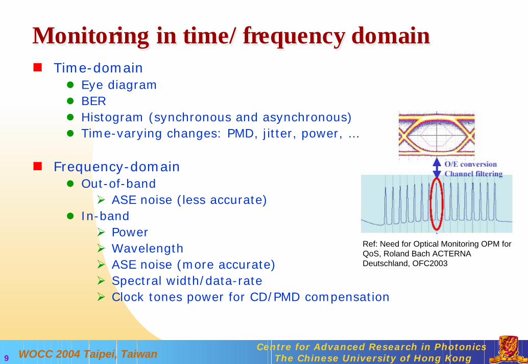
Compromise between cost and accuracyCompromise between cost and accuracy
OPM
Indirect BER Monitoring
Direct BER MonitoringOptical Layer Monitoring
Accuracy and complexity
Rel
ativ
e co
st
OCM
•Channel power
•Channel power•Channel wavelength•OSNR
Usages:• Diagnose system problems• Channel equalization• Link setup• Auto-discovery• Troubleshooting
Usages:• Channel equalization• Auto-discovery• Troubleshooting
Usages:• Evaluate end-to-end performance
• Ensure QoS and SLA
•Q-factor
•Digital Wrapper Frame
Ref: Alex Vukovic et al, “Performance Monitoring of Long-haul Networks”,Lightwave Magazine, July 22, 2002

WOCC 2004 Taipei, Taiwan Centre for Advanced Research in PhotonicsThe Chinese University of Hong Kong12
Making a judicious choiceMaking a judicious choiceConsiderations:
Right choice of monitoring/mitigation techniquesOptical monitoring techniques for WDM networksWill electronics mitigation techniques on channel-by-channel basis drive OPM unnecessary?
Suitable amount of monitoringEffectiveness Computation power (accuracy)Budget
Placement of monitoring points Within one network (all nodes or some strategic points)Inter-domain (ULH, metro, access, …)
Update Frequency

WOCC 2004 Taipei, Taiwan Centre for Advanced Research in PhotonicsThe Chinese University of Hong Kong13
OutlineOutline
Optical performance monitoring (OPM): Why is it needed?
Optical signal-to-noise ratio (OSNR) monitoring techniques
System design aspects + future perspectives
WOCC 2004 Taipei, Taiwan Centre for Advanced Research in PhotonicsThe Chinese University of Hong Kong14
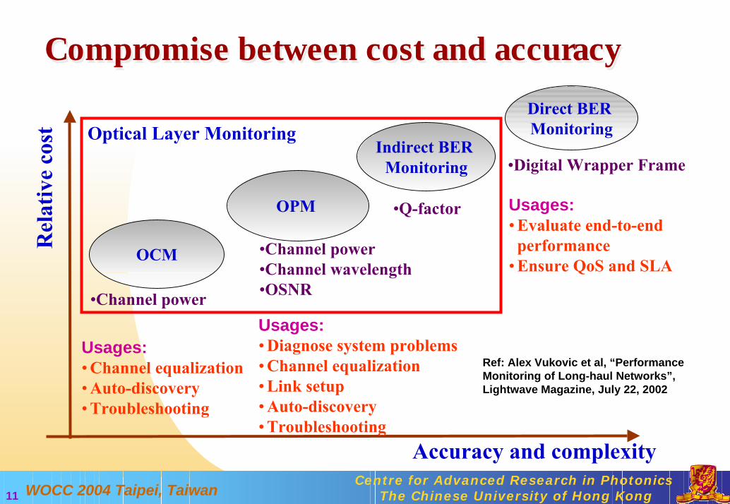
OSNR monitoring techniquesOSNR monitoring techniquesOSNR(dB) = 10log(Psig/PASE)Uses of OSNR in
Link setup, control, and optimizationIn-service characterization of optical signal qualityCorrelation with end terminal BER
Making OSNR measurements
λ
DWDM signals
Reference bandwidth (0.1nm)
Pnoise
Psig
Optical Power

WOCC 2004 Taipei, Taiwan Centre for Advanced Research in PhotonicsThe Chinese University of Hong Kong15
Reported OSNR monitoring techniquesReported OSNR monitoring techniquesOut-of-band: noise taken outside channel bandwidth
+: Measurable by traditional OSA-: Different EDFA gains for channels, effect of optical filtering,…
→ out-of-band noise ≠ in-band noise
In-band: noise taken within channel bandwidthElectrical spectral analysisPolarization-assisted optical power analysisSubcarrier CNR correlationMach-Zehnder interferometric method
λ
In-band ASE noise

WOCC 2004 Taipei, Taiwan Centre for Advanced Research in PhotonicsThe Chinese University of Hong Kong16
Electrical spectral analysisElectrical spectral analysisOrthogonal delayed-homodyne method
PBS PBS
∆τ Power meter
RF Spectrum AnalyzerPINFET
PCMonitoring signal
OSNR Monitoring Module
Total power
Electrical noise power
PMD Emulator
+: Bit-rate and modulation format independent +: Insensitive to PMD
-: Complexity-: High monitoring power required-: High resolution power measurement required-: Sensitive to chromatic dispersion
Electrical spectrum
w/o PMD emul.
w PMD emul.
fmeasure electrical noisepower at this null point
Ref: C. J. Youn et al, “OSNR Monitoring Technique Based on Orthogonal Delayed-Homodyne Method”, OFC 2002 & IEEE PTL Vol. 14, Oct 2002.

WOCC 2004 Taipei, Taiwan Centre for Advanced Research in PhotonicsThe Chinese University of Hong Kong17
Polarization-assisted power analysisPolarization-assisted power analysisMonitor by polarization-nulling or by degree-of-polarization (DOP)
+: Simple+: Relatively low monitoring power needed+: No electrical processing+: Large dynamic range
-: Sensitive to PMD
UnpolarizedPolarized
NoiseSignalPBS
Power meterPCMonitoring
signal
OSNR Monitoring Module (Polarization-nulling)
Power meter
½ASE
Signal + ½ASE
Ref: J. H. Lee et al, “OSNR Monitoring Technique using Polarization-Nulling Method”, IEEE PTL, Vol. 13, Jan 2001.
polarizer
PCMonitoring signal
OSNR Monitoring Module (DOP)
spectro-meter
DOP Analyzer
Ref: M. Petersson et al, “Multi-channel OSNR Monitoring for WDM networks”, ECOC 2002

WOCC 2004 Taipei, Taiwan Centre for Advanced Research in PhotonicsThe Chinese University of Hong Kong18
Polarization-assisted power analysisPolarization-assisted power analysisMonitor by polarization-nulling with off-center narrowband filtering
EDFA EDFA EDFA
Monitor
OSNR Monitoring Module
/4 Plate Linear Polarizer
Powermeter
Opticalfilter
Powermeter
Narrowbandoptical filter
λ
Monitoringsignal
Total power
Half ASEnoise power
1λ
8λ
…...
EDFA AW
G1λ
8λ
…...
Monitor Monitor Monitor
AWG
Ref: M. H. Cheung et al, “A PMD-insensitive OSNR Monitoring Scheme Based on Polarization-Nulling with Off-center Narrowband filtering”, Paper FF2, Proc. OFC’04.

WOCC 2004 Taipei, Taiwan Centre for Advanced Research in PhotonicsThe Chinese University of Hong Kong19
Polarization-assisted power analysisPolarization-assisted power analysisMonitor by polarization-nulling with off-center narrowband filtering – Robustness to PMD enhanced
(a) Conventional polarization-nulling
w/o PMD w/ PMD
Polarizer// signalOptical
clockOptical
clock
Carrier
Opticalfilter
Signal + half ASE noisemeasurement
Half ASE noise measurement
Signal + half ASE noisemeasurement
Half ASE noise measurement
Optical spectrum for 40-Gb/s 50% RZ signalPolarizer// signal
⊥Polarizer signal⊥
Polarizer signal
Serioussignal power
under-estimation!
Seriousnoise power
over-estimation!
Depolarization
w/o PMD w/ PMD
Opticalclock
Opticalclock
Carrier
Opticalfilter
Total power measurement Total power measurement
Half ASE noise measurementwithin narrower noiseequivalent bandwidth
⊥Polarizer signal
Polarizer higher-freq.
narrowband signal
⊥
(b) Proposed polarization-nulling with off-center narrowband filtering
Half ASE noise measurementwithin narrower noiseequivalent bandwidth
No total powerunder/over-estimation!
Only smallnoise power
over-estimation!

WOCC 2004 Taipei, Taiwan Centre for Advanced Research in PhotonicsThe Chinese University of Hong Kong20
Polarization-assisted power analysisPolarization-assisted power analysisMonitor by polarization-nulling with off-center narrowband filtering – Robustness to PMD enhanced
OSNR monitoring errors for 25-ps 10-Gb/s RZ-OOK data
DGD (ps)0 10 20 30 40 50O
SNR
mon
itorin
g er
rors
(dB
/0.1
nm)
-25
-20
-15
-10
-5
0
w/o. off-center narrowband filteringw. off-center narrowband filtering
OSNR monitoring errors for 2.5-ps 40-Gb/s OTDM RZ-OOK data
DGD (ps)0 10 20 30 40 50O
SNR
mon
itorin
g er
rors
(dB
/0.1
nm)
-50
-40
-30
-20
-10
0
filter without offset from carrierfilter offset at 1nm from carrierfilter offset at 2nm from carrierwithout narrowband filtering

WOCC 2004 Taipei, Taiwan Centre for Advanced Research in PhotonicsThe Chinese University of Hong Kong21
Subcarrier CNR correlationSubcarrier CNR correlationMonitor OSNR by correlation with carrier-to-noise ratio ofsubcarrier
Mod RF Spectrum AnalyzerPINFET
Monitoring signal
OSNR Monitoring ModuleTransmitter
16.7GHz
10Gb/s
Monitor carrier power
fRef: G. Rossi et al, “Optical Performance Monitoring in Reconfigurable WDM Optical Networks Using Subcarrier Multiplexing”, IEEE JLT Vol. 18, Dec 2000
subcarrierofdepthmodulation:mbandwidthoptical:
analyzerspectrumelectricalofbandwidthresolution:B
rationoise tocarrier:CNRm
CNRBOSNR
ESA
ESA
ν
ν
∆
−−∆
=2
+: Simultaneous multiple channel monitoring+: Simple
-: Extra bandwidth needed-: Sensitive to PMD and CD
WOCC 2004 Taipei, Taiwan Centre for Advanced Research in PhotonicsThe Chinese University of Hong Kong22
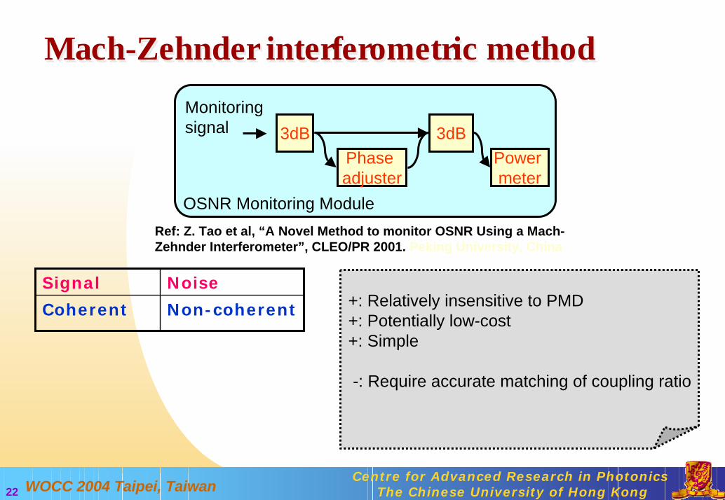
Mach-Zehnder interferometric method
Monitoring signal
OSNR Monitoring Module
Phase adjuster
Power meter
3dB 3dB
Mach-Zehnder interferometric method
Ref: Z. Tao et al, “A Novel Method to monitor OSNR Using a Mach-Zehnder Interferometer”, CLEO/PR 2001. Peking University, China
Non-coherentCoherent
NoiseSignal+: Relatively insensitive to PMD +: Potentially low-cost+: Simple
-: Require accurate matching of coupling ratio

WOCC 2004 Taipei, Taiwan Centre for Advanced Research in PhotonicsThe Chinese University of Hong Kong23
OSNR Monitoring StandardsOSNR Monitoring StandardsIndustry standards can be found at http://global.ihs.com/
BS EN 61280-2-9 Revision: 02 Chg: Date: 00/00/02FIBRE OPTIC COMMUNICATION SUBSYSTEM TEST PROCEDURES - PART 2-9: DIGITAL SYSTEMS - OPTICAL SIGNAL-TO-NOISE RATIO MEASUREMENT FOR DENSE WAVELENGTH-DIVISION MULTIPLEXED SYSTEMS
IEC 61280-2-9 Revision: 02 Chg: Date: 10/00/02FIBRE OPTIC COMMUNICATION SYBSYSTEM TEST PROCEDURES - PART 2-9: DIGITAL SYSTEMS - OPTICAL SIGNAL-TO-NOISE RATIO MEASUREMENT FOR DENSE WAVELENGTH-DIVISION MULTIPLEXED SYSTEMS
TIA/EIA-526-19 Revision: 00 Chg: Date: 06/00/00OFSTP-19 OPTICAL SIGNAL-TO-NOISE RATIO MEASUREMENT PROCEDURES FOR DENSE WAVELENGTH-DIVISION MULTIPLEXED SYSTEMS

WOCC 2004 Taipei, Taiwan Centre for Advanced Research in PhotonicsThe Chinese University of Hong Kong24
OutlineOutline
Optical performance monitoring (OPM): Why is it needed?
Optical signal-to-noise ratio (OSNR) monitoring techniques
System design aspects + future perspectives

WOCC 2004 Taipei, Taiwan Centre for Advanced Research in PhotonicsThe Chinese University of Hong Kong25
Features of advanced OPM techniquesFeatures of advanced OPM techniquesComprehensiveness:
making measurements on multiple parametersSimultaneous PMD and GVD monitoringSimultaneous PMD and OSNR monitoringSimultaneous wavelength, power, and path monitoring*
Integrate various functions (X+OPM) into a single, simple module
Fault localization:
*Ref: K.J. Pak et al., OFC’04 FF1
Ref: D. C. Kilper et al, “Monitoring optical network performance degradation due to amplifier noise”, JLT, Vol. 21, May 2003

WOCC 2004 Taipei, Taiwan Centre for Advanced Research in PhotonicsThe Chinese University of Hong Kong26
Centralized vs. Distributed OPMCentralized vs. Distributed OPMDistributed OPM
More information easily collected and processedCost and ways to integrate OPM with in-line components are of concern
Centralized OPMCollect information from other segments of optical transmission linksProcess information at a strategic point
Example: OTDR Fault localization capability is a desirable feature

WOCC 2004 Taipei, Taiwan Centre for Advanced Research in PhotonicsThe Chinese University of Hong Kong27
Other related researchOther related researchSensor NetworksComputer Tomography

WOCC 2004 Taipei, Taiwan Centre for Advanced Research in PhotonicsThe Chinese University of Hong Kong28
SummarySummaryOPM in next-generation high-speed transparent reconfigurablelong-haul networks is a key enabler
OPM comprises different tiers of monitoring to cater for different needs. Both optical surveillance schemes and OSNR monitoring are indispensable.
The key challenges for OPM: developing a cost-effective OPM technique and integrating OPM into different system design.

WOCC 2004 Taipei, Taiwan Centre for Advanced Research in PhotonicsThe Chinese University of Hong Kong29
Not Just a Bonus Element Not Just a Bonus Element
SLA fulfillment verificationQuality of service (QoS) provisioning
Dynamic CD + PMD monitoring and compensation
Active compensation
Fault detection, localization, and isolationResilience mechanism activation
Fault management
Relating OSNR with BEREarly signal degradation alarm
Signal quality characterization
Examples:Examples:Uses:Uses:
WOCC 2004 Taipei, Taiwan Centre for Advanced Research in PhotonicsThe Chinese University of Hong Kong30
OPM/Management & Control Plane CommunicationsOPM/Management & Control Plane Communications
Dissemination of monitoring signal to the corresponding network management unit and related network elements (NE)
How to design monitoring frequency and storage memory of NE? And also fault alarms, fault clearances and threshold setting?
How to optimize the network planning to provide highly reliable channels for monitor and control signal dissemination and regular channels for data transmission?
Further considerations in physical layer and higher layer protocolHorizontal communication between nodes to isolate the problem -GMPLS LMP’s “Link Verification” and “Fault Management”Inter-vendor collaboration

WOCC 2004 Taipei, Taiwan Centre for Advanced Research in PhotonicsThe Chinese University of Hong Kong31
Going 40Gb/s and beyond: How OPM advances?Going 40Gb/s and beyond: How OPM advances?
Optical diagnostics with high temporal resolution, high sensitivity, or phase sensitivity needed
High bandwidth optical RF spectrum measurement
High speed sampling techniques
Ref: C. Dorrer, “New techniques for high-speed optical characterization” Paper FF5, Proc. OFC’04.