Performance Improvement With Model Predictive Torque ... · conventional MPTC is claimed, the...
8
International Research Journal of Engineering and Technology (IRJET) e-ISSN: 2395-0056 Volume: 04 Issue: 07 | July -2017 www.irjet.net p-ISSN: 2395-0072 © 2017, IRJET | Impact Factor value: 5.181 | ISO 9001:2008 Certified Journal | Page 1623 Performance Improvement With Model Predictive Torque Control Of IM Drives Using Optimal Duty Cycle. B. Anjaiah 1 , S. Sridhar 2 1 PG Scholar, Dept. Of Electrical & Electronics Engineering, JNTUACEA, Anantapuramu, A.P., India 2 Asst.Professor, Dept. Of Electrical & Electronics Engineering, JNTUACEA, Anantapuramu, A.P., India ---------------------------------------------------------------------***-------------------------------------------------------------------- ABSTRACT- In order to get the high performance of induction motor drives model predictive torque control can be consider as one of the best scheme. When compared with direct torque control (DTC), MPTC is accurate in its voltage vector selection by employing system model directly with the finite switching states. Due to the limited number of voltage vectors in the two level inverter fed induction motor drives the sampling frequency should be maintained high for MPTC to get the good performances. By using MPTC we get the active vector and it’s vector duration is determined by different methods separately. By doing separate calculations of these two are cascaded, A poor low speed performance can be obtained by cascading the voltage vector calculation and it’s vector duration. In this situation to get better performance the sampling frequency still has to be maintained high. To reduce these type of problems an optimal duty cycle control is introduced in MPTC by inserting a null vector along with the selected voltage vector to reduce the torque ripple. In the advanced MPTC with optimal duty cycle control method both the voltage vector selection and it’s duration done simultaneously in order to reduce the torque and flux errors. By doing this simultaneous operation we get the better steady state performance at both low and high speeds even the sampling frequency is reduced by its half of the original value. INDEX TERMS: Direct torque control (DTC) , Model predictive torque control (MPTC), Induction motor (IM). 1. INTRODUCTION The direct torque control (DTC) is a powerful control scheme for ac machines which will suitable for variable speed drives especially in cases where torque control is more important than speed control. In DTC the voltage vector selection is done directly from predefined switching table according to the position of stator flux and error signs of both flux and torque. The advantages of the DTC are fast transient torque response and it is having a simple structure. Due to the hysteresis characteristics of control algorithm, DTC has two drawbacks. First, variable switching frequency and the second one is high flux and torque ripples. To remedy this problems different strategies are employed those are space vector modulation (SVM), duty cycle control and model predictive control (MPC). Among these methods, MPC was recently introduced as an effective alternative to the conventional DTC and has drawn increased attention from both academic and industrial communities. The application of model predictive control (MPC) in electrical drives includes model predictive current control (MPCC) and model predictive torque control (MPTC). Compared with the predictive current controller in rotor field oriented control methods which requires rotary transformation, MPTC is performed in stationary frame, hence it is much simpler. MPTC (model predictive torque control) can achieve less torque ripples than MPCC (model predictive current control), because the torque is directly controlled in MPTC. For high-performance drives, torque control rather than current control is more of concern, so in this paper MPTC is studied. In DTC the switching table is used and it can be replaced by an accurate system model in MPTC. MPTC can directly predict the evolution of variables concerned, such as torque and stator flux. By evaluating the influence of each possible voltage vector, the one minimizing the torque and flux errors is selected as the best voltage vector. By doing this the vector selected from MPTC is more accurate and effective than that from conventional DTC. Apart from its intuitive concept and fast dynamic response, the high flexibility of MPTC also allows the controller to take system non-linearity’s and constraints into account such as neutral point voltage balance, restricting large starting current and reactive power control. The advantages of MPTC make it a powerful approach when high-performance control of motor drives is required. However, as the number of voltage vectors provided by a two-level inverter is rather limited (only eight vectors), the torque and flux ripples obtained from conventional MPTC are higher than those obtained from a multilevel inverter or a matrix converter. In order to improve the steady-state performance of MPTC, the sampling frequency has to be high, which requires high computational ability. Furthermore, high amount of calculation is required in MPTC due to the predictions of both stator flux and current for each voltage vector. Hence, in MPTC improving the steady torque
Transcript of Performance Improvement With Model Predictive Torque ... · conventional MPTC is claimed, the...

International Research Journal of Engineering and Technology (IRJET) e-ISSN: 2395-0056
Volume: 04 Issue: 07 | July -2017 www.irjet.net p-ISSN: 2395-0072
© 2017, IRJET | Impact Factor value: 5.181 | ISO 9001:2008 Certified Journal | Page 1623
Performance Improvement With Model Predictive Torque Control Of IM Drives Using Optimal Duty Cycle.
B. Anjaiah1, S. Sridhar2
1PG Scholar, Dept. Of Electrical & Electronics Engineering, JNTUACEA, Anantapuramu, A.P., India 2Asst.Professor, Dept. Of Electrical & Electronics Engineering, JNTUACEA, Anantapuramu, A.P., India
---------------------------------------------------------------------***--------------------------------------------------------------------ABSTRACT- In order to get the high performance of induction motor drives model predictive torque control can be consider as one of the best scheme. When compared with direct torque control (DTC), MPTC is accurate in its voltage vector selection by employing system model directly with the finite switching states. Due to the limited number of voltage vectors in the two level inverter fed induction motor drives the sampling frequency should be maintained high for MPTC to get the good performances. By using MPTC we get the active vector and it’s vector duration is determined by different methods separately. By doing separate calculations of these two are cascaded, A poor low speed performance can be obtained by cascading the voltage vector calculation and it’s vector duration. In this situation to get better performance the sampling frequency still has to be maintained high. To reduce these type of problems an optimal duty cycle control is introduced in MPTC by inserting a null vector along with the selected voltage vector to reduce the torque ripple. In the advanced MPTC with optimal duty cycle control method both the voltage vector selection and it’s duration done simultaneously in order to reduce the torque and flux errors. By doing this simultaneous operation we get the better steady state performance at both low and high speeds even the sampling frequency is reduced by its half of the original value. INDEX TERMS: Direct torque control (DTC) , Model predictive torque control (MPTC), Induction motor (IM).
1. INTRODUCTION The direct torque control (DTC) is a powerful control scheme for ac machines which will suitable for variable speed drives especially in cases where torque control is more important than speed control. In DTC the voltage vector selection is done directly from predefined switching table according to the position of stator flux and error signs of both flux and torque. The advantages of the DTC are fast transient torque response and it is having a simple structure. Due to the hysteresis characteristics of control algorithm, DTC has two drawbacks. First, variable switching frequency and the second one is high flux and torque ripples. To remedy this problems different strategies are employed those are space vector
modulation (SVM), duty cycle control and model predictive control (MPC). Among these methods, MPC was recently introduced as an effective alternative to the conventional DTC and has drawn increased attention from both academic and industrial communities.
The application of model predictive control (MPC) in electrical drives includes model predictive current control (MPCC) and model predictive torque control (MPTC). Compared with the predictive current controller in rotor field oriented control methods which requires rotary transformation, MPTC is performed in stationary frame, hence it is much simpler. MPTC (model predictive torque control) can achieve less torque ripples than MPCC (model predictive current control), because the torque is directly controlled in MPTC. For high-performance drives, torque control rather than current control is more of concern, so in this paper MPTC is studied.
In DTC the switching table is used and it can be replaced by an accurate system model in MPTC. MPTC can directly predict the evolution of variables concerned, such as torque and stator flux. By evaluating the influence of each possible voltage vector, the one minimizing the torque and flux errors is selected as the best voltage vector. By doing this the vector selected from MPTC is more accurate and effective than that from conventional DTC. Apart from its intuitive concept and fast dynamic response, the high flexibility of MPTC also allows the controller to take system non-linearity’s and constraints into account such as neutral point voltage balance, restricting large starting current and reactive power control. The advantages of MPTC make it a powerful approach when high-performance control of motor drives is required. However, as the number of voltage vectors provided by a two-level inverter is rather limited (only eight vectors), the torque and flux ripples obtained from conventional MPTC are higher than those obtained from a multilevel inverter or a matrix converter.
In order to improve the steady-state performance
of MPTC, the sampling frequency has to be high, which requires high computational ability. Furthermore, high amount of calculation is required in MPTC due to the predictions of both stator flux and current for each voltage vector. Hence, in MPTC improving the steady torque

International Research Journal of Engineering and Technology (IRJET) e-ISSN: 2395-0056
Volume: 04 Issue: 07 | July -2017 www.irjet.net p-ISSN: 2395-0072
© 2017, IRJET | Impact Factor value: 5.181 | ISO 9001:2008 Certified Journal | Page 1624
performance and reducing the control complexity have become important constraints.
In DTC, it has been known that high torque ripple
is partly caused by the application of a single voltage vector during the whole control period. In MPTC, although the selected vector is more accurate and effective in reducing torque and flux errors, applying a single voltage vector during the whole control period still fails to reduce the torque and flux errors to the minimal value. In DTC by inserting null vector along with voltage vector during one control period achieve moderate and accurate torque ripple reduction. The null vector generally produces small variations on both torque and flux. Hence, it is possible to reduce the torque ripple by allocating a fraction of control period to an appropriate null vector. This Principle has been widely studied in DTC and various methods have been proposed to obtain the duration of the selected vector, for example, torque ripple minimization, deadbeat torque control and mean torque control.
Recently, the concept of duty cycle control has
also been applied in MPTC. In this MPTC, active vector duration can be done by three different ways first one is torque ripple minimization and second one least square optimization and the third one is dead beat control. Torque ripple which is used to calculate the optimal weighting factor and the control period is divided into two intervals to achieve further torque ripple reduction. The equation to obtain the optimal weighting factor is complicated and parameter dependent. The principle of torque ripple minimization is employed to calculate the duration of the active vector and a fixed weighting factor is used. Although better steady-state performance than conventional MPTC is claimed, the results are obtained under the same sampling frequency as that of conventional MPTC. Furthermore, the active vector selection is first executed and then its duration is calculated. This cascaded processing leads to relative poor low-speed performance.
An improved MPTC with optimal duty cycle
control method which is able to achieve better steady-state performance with much lower sampling frequency. In MPTC with torque ripple minimization technique optimizes vector selection and duty ratio separately; this paper does these optimizations simultaneously. This is based on the consideration that the active vector selected from conventional MPTC may be no longer than the optimal one when a zero voltage vector is inserted along with it. The duration of the active vector is obtained based on the principle of deadbeat torque control, which is also different from the torque ripple minimization strategy. To ensure good performance of MPTC in practical application, accurate stator flux and torque estimation are essential. In this paper, a full order observer with constant gain matrix is adopted due to its accuracy over a wide speed range.
Furthermore, control delay caused by digital processing is compensated and the strategy of pre excitation is implemented to avoid large starting current while obtaining sufficient starting torque. The proposed MPTC With duty cycle is compared with conventional MPTC and the improved MPTC. Simulation and experimental results prove that, better steady-state performance is achieved for the proposed MPTC especially in the low-speed range, even if the sampling frequency is reduced by half.
II. DYNAMIC EQUATIONS OF IM The dynamic equations of IM with stator flux and stator currents as state variables can be expressed in stationary frame (1) Where X=[( ]
are state variables, u = us is the stator voltage vector, and
A= [ [ ] ( )
] (2)
B=* + (3)
, stator resistance, rotor resistance , , Lm stator inductance, rotor inductance and mutual inductance. ωr electrical rotor speed
λ=
The prediction of the stator current and stator flux at the next Sampling instant can be obtained from (1). To ensure good accuracy of the prediction, second-order Euler method is employed.

International Research Journal of Engineering and Technology (IRJET) e-ISSN: 2395-0056
Volume: 04 Issue: 07 | July -2017 www.irjet.net p-ISSN: 2395-0072
© 2017, IRJET | Impact Factor value: 5.181 | ISO 9001:2008 Certified Journal | Page 1625
{ ( ) ( ) ( ( ) ( ))
( ) ( )
( ( ) ( ))
(4)
where is control period ( ) is predictor-
corrector of state vector; ( ) [ ( ) ( )]
is pre-dicted state vector for stator current and stator flux. The main difference between xp(k + 1) and x(k + 1) is that xp(k+1) is calculated as a rough approximation of x(k+1) in the first step, which is equivalent to forward Euler integration. The value of xp(k + 1) is refined in the second step to obtain more accurate result of x(k + 1), which is equivalent to trapezoidal integration method . It is possible to use more advanced method to obtain accurate discretization of (1), such as Cayley–Hamilton theorem in, but the computation burden will be significantly increased, so it is not adopted in this paper. The electromagnetic torque can be predicted as
( )
( ) ( ) (5)
Where Np is the number of pole pairs and represents cross product. Omitting the tedious deduction process, the differentiation of torque Te with respect to time t can be obtained from (1) and(5)
=1.5 λ [ ( ) (
)
( ) (
)] (6)
Where ٭ represents the conjugation of a complex vector. The equation in (6) provides a practical method to calculate the slope of torque, which is useful for the aim of improving torque performance in Section III. For simplicity, the torque slope caused by a zero vector u0 and a nonzero voltage vector ui are represented by s0 and si , respectively, which are expressed as
λ [ ( ) (
)
( )] (7)
λ (
) (8)
III. PROPOSED MPTC WITH OPTIMAL DUTY
CYCLE CONTROL
In the proposed diagram of MPTC torque reference is generated by an external speed control loop and the stator flux amplitude reference is kept constant because the flux-weakening operations not considered in this paper. The control diagram consisting of A. Flux and torque estimation B.vector selection and duty ratio optimization C. Digital delay optimization D.machine magnetization
A. Flux and Torque Estimation To maintain good performance of MPTC the flux and torque estimation should be accurate. A full order observer is adopted and it is having good accuracy over a wide speed range. The error feedback of stator current is introduced, the accuracy of estimation is increased and the observer is more robust against the motor parameter variations. The mathematical model of the observer is based on the IM model in (1), which is expressed as
( ) (9)
Where [ ] are the estimated state variable .
The observer poles of IM drives is proportional to the poles of IM and its factor is greater than one (k>1) which produces high imaginary part at high speed and is harmful to the system stability. To remedy these problems the imaginary part of the observer poles should remain unchanged and real part of observer poles should be changed to left in the complex plane compared to the poles of IM. However, this leads to complicated expressions of observer gains. so to eliminate all those problems a very simple constant gain matrix G is employed to improve stability of the observer and it can be expressed as
[
(λ )⁄ ] (10)
Where b is negative constant gain. This pole placement method can improve the convergence and stability of observer especially at high speed and is simple to implement. B. Vector Selection and Duty Ratio Determination 1. Predictive torque model
It can be seen that the torque reference is generated by an external speed control loop while the reference for the stator flux magnitude is kept constant. The basic operation of the predictive controller can be explained as
Fig. 2. Predictive torque control diagram.

International Research Journal of Engineering and Technology (IRJET) e-ISSN: 2395-0056
Volume: 04 Issue: 07 | July -2017 www.irjet.net p-ISSN: 2395-0072
© 2017, IRJET | Impact Factor value: 5.181 | ISO 9001:2008 Certified Journal | Page 1626
1) Stator currents and rotor speed are measured. 2) These measurements are used for prediction of torque and stator flux for all seven different voltage vectors 3) The seven predictions are evaluated using the cost function (Cost function block). 4) The voltage vector that minimizes the cost function is selected and applied in the machine terminals. 2. Conventional MPTC
In conventional MPTC the stator flux and electromagnetic torque at (k + 1)th instant are predicted using predictive model ,with the variables of is(k) and ψs (k) as the initial states. The aim of the cost function is to force both stator flux and torque to track their respective reference value. In other words error between estimated value and reference value of stator flux and torque should be minimized.
J=| ( )|+ ||
| ( ) | (11)
where denotes the weighting factor for stator flux. To
assign the same weight on torque and stator flux, is
usually chosen as
(12)
Where Tn is the rated torque and |ψsn | is the rated amplitude of stator flux. It should be noted that the weighting factor kψ in (12) is only used as a starting point for tuning work, and the final practical value of kψ may be larger than that in (12). As can be seen from the first row of matrix A in (2), the prediction of is (k + 1) is complicated. As the stator current is not directly used in the cost function of conventional MPTC, the prediction of stator current may be eliminated for the aim of control complexity reduction. To predict the torque at (k + 1)th instant without the prediction of stator current, (5) is replaced by
( )
( ) ( ) (13)
Where isλ(k) is calculated based on the variables at kth
instant
( ) ( ) ( )+ (
) ( ) (14)
By using (13) and (14), prediction of stator current is(k+1) is no longer needed for obtaining Te (k), hence reducing the calculation burden.
3. Proposed MPTC with optimal duty cycle control:
Fig . 3. Voltage vector and corresponding switching states
of two level inverter.
There are eight discrete voltage vectors available: u0 ,u1. . .u7 for a two-level inverter-fed IM drive. In conventional MPTC the voltage vector which minimizes the cost function can be applied to whole control period. Due to this sampling frequency is maintained high to get better performance. The torque performance can be further improved by dividing the vector calculation and its duration separately .this separate calculation both vector and its duration cannot ensure performance improvement for all speeds of MPTC. The low-speed performance of MPTC with duty cycle control is not satisfactory at low speed. The reason lies in that the fact that the selected vector is optimal only makes sense when it is applied in the whole control period. When a zero vector is inserted along with the active vector and the duration of the active vector changes
In the proposed method of optimal duty cycle
control The vector calculation and its optimal duration can be done simultaneously The duty ratio of the active voltage vector is obtained based on the principle of deadbeat control of torque . The reason of choosing deadbeat fashion is that it is consistent with the definition of cost function in (11), which is composed of linear combination of control variable errors between actual value and reference for the purpose of reference tracking. On the contrary, other kinds of duty ratio optimization methods, like torque ripple minimization and mean torque control, are not in accordance to the aim of reference tracking in the cost function. Furthermore, the expressions of duty ratio obtained from mean torque control is relatively complex and time consuming, which is unfavorable for real-time implementation. So, in this paper, the simple deadbeat torque control is adopted. According to the principle of deadbeat torque control, the torque at (k + 1)th instant should reach its reference value Tref when the selected voltage vector ui is applied for a fraction of control period. This is expressed as
( ) ( ) ( ) (15)
Where is the optimal duration of the active vector; s0
and si are the torque slope caused by a zero vector u0 and

International Research Journal of Engineering and Technology (IRJET) e-ISSN: 2395-0056
Volume: 04 Issue: 07 | July -2017 www.irjet.net p-ISSN: 2395-0072
© 2017, IRJET | Impact Factor value: 5.181 | ISO 9001:2008 Certified Journal | Page 1627
a nonzero voltage vector ui , as introduced in (7) and (8). Solving (15), the optimal duration for the active
vector can be obtained as
= ( )
(16)
It should be noted that the optimal duration topt is limited to the range of [0, Tsc ] in practical application . For two-level inverter, there are six active voltage vectors ui(i = 1. . . . .6), as shown in Fig. 2. For each active vector, the duration ti is first determined using (16). The active vector ui multiplied by its duration ti is used as voltage input in (1) to obtain the torque and stator flux at (k+1)th instant, which are subsequently evaluated using cost function (11). The one minimizing the cost function is selected as the best voltage vector and it will be applied for its optimal duration in the next control period. Compared to the MPTC with separate duty cycle control, the proposed MPTC is more accurate and effective for active vector selection due to the consideration of its duration in the cost function evaluation. 3) Relationship Between MPTC and Deadbeat Control:
The deadbeat controller is used to minimize the error between the reference and feedback value at the end of next step in the proposed system. Due to the limited voltage vectors, generally it cannot achieve “deadbeat control” in true sense. To get the better performance applying the selected optimal voltage vector for an optimal duration topt to minimize both the torque and flux errors. Conventional deadbeat torque control requires a modulation stage (such as SVM)that is because of the reference voltage vector which forces feedback value equal to its reference at the end of next step. Compared to conventional deadbeat torque control, the proposed MPTC takes the discrete nature of power converters into account and selects the best voltage vector by minimizing a predefined cost function. Hence, no modulation stage is required. Furthermore, it also presents some merits inherited, such as optimality, flexibility to incorporate constrains in cost function. C. Digital Delay Compensation A simple solution to compensate this delay is to take into account the calculation time and apply the selected switching state after the next sampling instant. This way, the control algorithm is modified as follows: 1) measurement of the load currents; 2)application of the switching state (calculated in the previous interval); 3) estimation of the value of the currents at time tk+1, considering the applied switching state;
4) prediction of the load currents for the next sampling instant tk+2 for all possible switching states; 5) evaluation of the cost function for each prediction; 6) Selection of the switching state that minimizes the cost function.
Fig.4. Flow chart of the proposed MPTC with consideration of time delay compensation
In real-time implementation, one-step delay
between the commanding voltage and the real voltage caused by digital processing will deteriorate the performance of MPTC. To compensate this delay, the variables at (k+2)th instant rather than (k + 1)th instant should be predicted for the evaluation of the cost function. In this paper, a model-based prediction is adopted to diminish the influence of the time delay. The stator current and stator flux at kth instant are first estimated, as introduced in Section III-A, which provides initial values for the state variables at (k + 1)th instant. The predictions of is(k+1) and ψs(k + 1) are subsequently executed according to (4). The final value of ψs (k + 2) and Te(k+2) are obtained from (4) and (13) by replacing the kth and (k+1)th variables with the (k+1)th and (k+2)th variables. Note that the prediction of is (k + 2) is no longer required due to the simplification in (13). After compensation of the one-step delay, the final cost function in (11) should be updated with the variables at (k+2)th instant. The overall flow chart of the proposed MPTC with optimal duty cycle

International Research Journal of Engineering and Technology (IRJET) e-ISSN: 2395-0056
Volume: 04 Issue: 07 | July -2017 www.irjet.net p-ISSN: 2395-0072
© 2017, IRJET | Impact Factor value: 5.181 | ISO 9001:2008 Certified Journal | Page 1628
conventional MPTC, such as the notion of optimality, flexibility to incorporate constrains in cost function, etc. D. Machine magnetization
As the stator current is not directly controlled by MPTC, Starting the IM directly without current limitations may result in large start-up stator current when a high starting torque is required. To decrease the starting current and maintain sufficient starting torque, the stator flux should be first established. The process of machine magnetization is called pre-excitation, which is achieved by the current chopping control.
During the process of preexcitation, if the current
exceeds the limitation setting, a zero vector will be applied to reduce the current; otherwise a fixed active vector will be applied to establish the stator flux. When the amplitude of stator flux reaches the expected value, which is set as 95% of the reference stator flux amplitude in this paper, the process of preexcitation terminates and the motor can start safely with sufficient torque.
IV. SIMULATION RESULTS
fig.5. Steady state performance of conventional MPTC at 150 r/min with rated load.
Fig. 6. Steady state performance of MPTC at 1500r/min with rated load.
Fig. 7. Steady state performance of MPTC I at 150 r/min with rated load.
MPTC I is nothing but the MPTC with separate
optimal duty cycle control and MPTC II be the proposed method. Here MPTCI can be taken for comparison. It should be noted that, to be consistent with the cost function definition and for the aim of fair comparison, the duty ratio determination method of torque ripple minimization in MPTC I is replaced by deadbeat torque control in this paper. In this proposed system flux reference is constant and it be taken as 0.94 wb. As weighting factor kψ in the cost function is the only parameter to adjust in MPTC, some tuning work has to be done to select the most appropriate value of kψ. However, currently the selection of weighting factor is still an open problem and usually determined by a heuristic procedure. The final value of the weighing factor kψ is set to 100 in this paper, which is based on extensive simulations and experimental tests and applied to all three MPTC methods. To confirm the superiority of MPTC II, the sampling frequency is set to 10 kHz, while the sampling frequency of conventional MPTC and MPTC I is 20 kHz. In spite of the much lower sampling frequency, MPTC II exhibits better steady-state performance due to the simultaneous processing of vector selection and its duty ratio.
International Research Journal of Engineering and Technology (IRJET) e-ISSN: 2395-0056
Volume: 04 Issue: 07 | July -2017 www.irjet.net p-ISSN: 2395-0072
© 2017, IRJET | Impact Factor value: 5.181 | ISO 9001:2008 Certified Journal | Page 1629
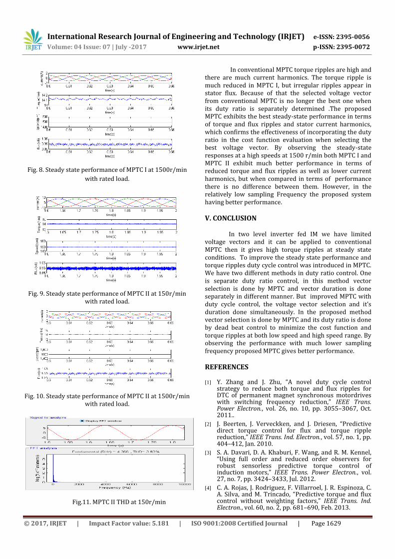
Fig. 8. Steady state performance of MPTC I at 1500r/min
with rated load.
Fig. 9. Steady state performance of MPTC II at 150r/min
with rated load.
Fig. 10. Steady state performance of MPTC II at 1500r/min
with rated load.
Fig.11. MPTC II THD at 150r/min
In conventional MPTC torque ripples are high and there are much current harmonics. The torque ripple is much reduced in MPTC I, but irregular ripples appear in stator flux. Because of that the selected voltage vector from conventional MPTC is no longer the best one when its duty ratio is separately determined .The proposed MPTC exhibits the best steady-state performance in terms of torque and flux ripples and stator current harmonics, which confirms the effectiveness of incorporating the duty ratio in the cost function evaluation when selecting the best voltage vector. By observing the steady-state responses at a high speeds at 1500 r/min both MPTC I and MPTC II exhibit much better performance in terms of reduced torque and flux ripples as well as lower current harmonics, but when compared in terms of performance there is no difference between them. However, in the relatively low sampling Frequency the proposed system having better performance.
V. CONCLUSION In two level inverter fed IM we have limited
voltage vectors and it can be applied to conventional MPTC then it gives high torque ripples at steady state conditions. To improve the steady state performance and torque ripples duty cycle control was introduced in MPTC. We have two different methods in duty ratio control. One is separate duty ratio control, in this method vector selection is done by MPTC and vector duration is done separately in different manner. But improved MPTC with duty cycle control, the voltage vector selection and it’s duration done simultaneously. In the proposed method vector selection is done by MPTC and its duty ratio is done by dead beat control to minimize the cost function and torque ripples at both low speed and high speed range. By observing the performance with much lower sampling frequency proposed MPTC gives better performance.
REFERENCES [1] Y. Zhang and J. Zhu, “A novel duty cycle control
strategy to reduce both torque and flux ripples for DTC of permanent magnet synchronous motordrives with switching frequency reduction,” IEEE Trans. Power Electron., vol. 26, no. 10, pp. 3055–3067, Oct. 2011..
[2] J. Beerten, J. Verveckken, and J. Driesen, “Predictive direct torque control for flux and torque ripple reduction,” IEEE Trans. Ind. Electron., vol. 57, no. 1, pp. 404–412, Jan. 2010.
[3] S. A. Davari, D. A. Khaburi, F. Wang, and R. M. Kennel, “Using full order and reduced order observers for robust sensorless predictive torque control of induction motors,” IEEE Trans. Power Electron., vol. 27, no. 7, pp. 3424–3433, Jul. 2012.
[4] C. A. Rojas, J. Rodriguez, F. Villarroel, J. R. Espinoza, C. A. Silva, and M. Trincado, “Predictive torque and flux control without weighting factors,” IEEE Trans. Ind. Electron., vol. 60, no. 2, pp. 681–690, Feb. 2013.

International Research Journal of Engineering and Technology (IRJET) e-ISSN: 2395-0056
Volume: 04 Issue: 07 | July -2017 www.irjet.net p-ISSN: 2395-0072
© 2017, IRJET | Impact Factor value: 5.181 | ISO 9001:2008 Certified Journal | Page 1630
[5] Y. Zhang, W. Xie, Z. Li, and Y. Zhang, “Model predictive direct power control of a PWM rectifier with duty cycle optimization,” IEEE Trans. Power Electron., vol. 28, no. 11, pp. 5343–5351, 2013.
[6] H. Miranda, P. Cortes, J. Yuz, and J. Rodriguez, “Predictive torque control of induction machines based on state-space models,” IEEE Trans. Ind. Electron., vol. 56, no. 6, pp. 1916–1924, Jun. 2009.
[7] Y. Zhang and H.Yang, “Torque ripple reduction of model predictive torque control of induction motor drives,” in Proc. IEEE Energy Convers. Congr. Expo., 2013, pp. 1176–1183.
[8] M. Nemec, D. Nedeljkovic, and V. Ambrozic, “Predictive torque control of induction machines using immediate flux control,” IEEE Trans. Ind.Electron., vol. 54, no. 4, pp. 2009–2017, Aug. 2007.
[9] B. Kenny and R. Lorenz, “Stator- and rotor-flux-based deadbeat direct torque control of induction machines,” IEEE Trans. Ind. Appl., vol. 39, no. 4, pp. 1093–1101, Jul./Aug. 2003.
[10] P. Cortes, J. Rodriguez, C. Silva, and A. Flores, “Delay compensation in model predictive current control of a three-phase inverter,” IEEE Trans. Ind. Electron., vol. 59, no. 2, pp. 1323–1325, Feb. 2012.