Performance Evaluation of Transmission Line Protection...
11
(IJACSA) International Journal of Advanced Computer Science and Applications, Vol. 8, No. 8, 2017 89 | Page www.ijacsa.thesai.org Performance Evaluation of Transmission Line Protection Characteristics with DSTATCOM Implementation Yasar Khan Department of Electrical CECOS University of IT and Emerging Sciences, Peshawar, Pakistan Khalid Mahmood Department of Electrical CECOS University of IT and Emerging Sciences, Peshawar, Pakistan Sanaullah Ahmad Department of Electrical Engineering, IQRA National University (INU), Peshawar, Pakistan Abstract—To meet with the ever-enhancing load demands, new transmission lines should be bolted-on in the existing power system but the economic and environmental concerns are major constraints to this addition. Hence utilities have to rely on the existent power system infrastructure with some modifications. To enhance controllability and boost power transfer potential of the existing power system the use of Flexible Alternating Current Transmission System (FACTS) device is the most viable modification. FACTS devices include Static VAR Compensator (SVC), thyristor controlled series capacitor (TCSC), Thyristor Controlled Reactor (TCR), Thyristor Switched Capacitor (TSC) and Self Commutated VAR compensators i.e. Static Synchronous Compensator (DSTATCOM). Among the FACTS devices, DSTATCOM is the most feasible choice because of its capability to furnish both leading and lagging reactive power, faster response time in comparison with others, smaller harmonic content, inrush current generation is minimum and the dynamic performance with variations of voltage is quite good. DSTATCOM has the ability to have effective control over various issues concerning AC power transmission. However, the Parameters of the protection devices in the present power system are set without taking into account the reaction of these FACTS devices. So in order to ascertain stability and reliability of power system, reaction of FACTS devices with the existent protection schemes must be thoroughly investigated. This paper aims to explore the deviations in the performance characteristics of transmission line protection due to installation of DSTATCOM on a 220KV EHV transmission line using theoretical as well as MATLAB/SIMULINK simulation models. The dynamic performance of a DSTATCOM connected to an existing transmission line system is evaluated when large industrial induction motor is started and voltage sags are introduced. Keywords—Power system analysis; DSTATCOM; transmission line loss minimization; distribution dynamic compensation; transmission losses and efficiency I. INTRODUCTION Industrial and domestic development has led to increased electrical energy demand day to day. To avoid power system instability, the existing power networks are being growingly interconnected. To cope with the ever-growing electrical energy demands, the existing transmission systems are often run at or more than their rated capacity which leads to problems in maintaining effective power flow distribution. The intuitive and obvious solution to this problem is to construct new transmission lines but environmental and economic issues are major hurdles to this solution. So, we have to rely on the existing power system infrastructure with requisite modifications to fully utilize the capability of transmission system. These modifications necessarily involve “reactive power compensation” and initial solutions were capacitor banks and shunt reactors, but these proved to be very rigid and inefficient way outs. To achieve better controllability and escalated capability of transferring electrical power of present power system, FACTS devices were developed. While we have achieved improved efficiency of power system employing the FACTS devices, it is altogether very important that the power system must be “Reliable” and “Dependable” to ensure stability of Power system [17]. These requirements of dependability and reliability are intemperately influenced by the installed power system protection. A dependable protection system must give tripping for faults within its defined zone and a reliable protection system must not fail to operate when it is called for its duty/function. Both of these factors lead to desirable Stable Power System. Different attributes of power system lead to various protective Relays e.g. over current relay, differential relay, Over voltage relay, etc. The major protection scheme for transmission systems is furnished with the distance/impedance relays. The principle on which the distance relay is modeled, when FACTS devices are installed within their defined protection zone, has led to the challenges that were not taken into account during development of protection devices and their parameter settings. Among FACTS devices, DSTATCOM is the most feasible choice for power flow control due to its desirable features and is the subject of this Paper. II. FACTS DEVICES The detailed literature survey depicts the increasing trends in the field of reactive power compensation incorporating FACTS devices to furnish greater controllability and escalated transfer capability of power. Researches also grabbed attention of concerned quarter about the influence of FACTS devices on dynamics of power system. Extensive studies pointed out the side effects of trending FACTS devices because these devices greatly influenced the dynamics of power system. Due to this
Transcript of Performance Evaluation of Transmission Line Protection...

(IJACSA) International Journal of Advanced Computer Science and Applications,
Vol. 8, No. 8, 2017
89 | P a g e
www.ijacsa.thesai.org
Performance Evaluation of Transmission Line
Protection Characteristics with DSTATCOM
Implementation
Yasar Khan
Department of Electrical CECOS
University of IT and Emerging
Sciences, Peshawar, Pakistan
Khalid Mahmood
Department of Electrical CECOS
University of IT and Emerging
Sciences, Peshawar, Pakistan
Sanaullah Ahmad
Department of Electrical
Engineering, IQRA National
University (INU), Peshawar,
Pakistan
Abstract—To meet with the ever-enhancing load demands,
new transmission lines should be bolted-on in the existing power
system but the economic and environmental concerns are major
constraints to this addition. Hence utilities have to rely on the
existent power system infrastructure with some modifications. To
enhance controllability and boost power transfer potential of the
existing power system the use of Flexible Alternating
Current Transmission System (FACTS) device is the most viable
modification. FACTS devices include Static VAR Compensator
(SVC), thyristor controlled series capacitor (TCSC), Thyristor
Controlled Reactor (TCR), Thyristor Switched Capacitor (TSC)
and Self Commutated VAR compensators i.e. Static Synchronous
Compensator (DSTATCOM). Among the FACTS devices,
DSTATCOM is the most feasible choice because of its capability
to furnish both leading and lagging reactive power, faster
response time in comparison with others, smaller harmonic
content, inrush current generation is minimum and the dynamic
performance with variations of voltage is quite good.
DSTATCOM has the ability to have effective control over
various issues concerning AC power transmission. However, the
Parameters of the protection devices in the present power system
are set without taking into account the reaction of these FACTS
devices. So in order to ascertain stability and reliability of power
system, reaction of FACTS devices with the existent protection
schemes must be thoroughly investigated. This paper aims to
explore the deviations in the performance characteristics of
transmission line protection due to installation of DSTATCOM
on a 220KV EHV transmission line using theoretical as well as
MATLAB/SIMULINK simulation models. The dynamic
performance of a DSTATCOM connected to an existing
transmission line system is evaluated when large industrial
induction motor is started and voltage sags are introduced.
Keywords—Power system analysis; DSTATCOM; transmission
line loss minimization; distribution dynamic compensation;
transmission losses and efficiency
I. INTRODUCTION
Industrial and domestic development has led to increased electrical energy demand day to day. To avoid power system instability, the existing power networks are being growingly interconnected. To cope with the ever-growing electrical energy demands, the existing transmission systems are often run at or more than their rated capacity which leads to problems in maintaining effective power flow distribution.
The intuitive and obvious solution to this problem is to construct new transmission lines but environmental and economic issues are major hurdles to this solution. So, we have to rely on the existing power system infrastructure with requisite modifications to fully utilize the capability of transmission system. These modifications necessarily involve “reactive power compensation” and initial solutions were capacitor banks and shunt reactors, but these proved to be very rigid and inefficient way outs. To achieve better controllability and escalated capability of transferring electrical power of present power system, FACTS devices were developed.
While we have achieved improved efficiency of power system employing the FACTS devices, it is altogether very important that the power system must be “Reliable” and “Dependable” to ensure stability of Power system [17]. These requirements of dependability and reliability are intemperately influenced by the installed power system protection. A dependable protection system must give tripping for faults within its defined zone and a reliable protection system must not fail to operate when it is called for its duty/function. Both of these factors lead to desirable Stable Power System. Different attributes of power system lead to various protective Relays e.g. over current relay, differential relay, Over voltage relay, etc. The major protection scheme for transmission systems is furnished with the distance/impedance relays. The principle on which the distance relay is modeled, when FACTS devices are installed within their defined protection zone, has led to the challenges that were not taken into account during development of protection devices and their parameter settings. Among FACTS devices, DSTATCOM is the most feasible choice for power flow control due to its desirable features and is the subject of this Paper.
II. FACTS DEVICES
The detailed literature survey depicts the increasing trends in the field of reactive power compensation incorporating FACTS devices to furnish greater controllability and escalated transfer capability of power. Researches also grabbed attention of concerned quarter about the influence of FACTS devices on dynamics of power system. Extensive studies pointed out the side effects of trending FACTS devices because these devices greatly influenced the dynamics of power system. Due to this

(IJACSA) International Journal of Advanced Computer Science and Applications,
Vol. 8, No. 8, 2017
90 | P a g e
www.ijacsa.thesai.org
disturbance, many subsystems of power system are affected and the Protection system is the one that is highly impacted by this disturbance. In fact the question of disturbance in the protection system would have been raised since the introduction of capacitor banks or Shunt reactor as compensating devices but their dynamic behavior and response time were quite slower to actually affect the fast responding protection system.
Some research works have already been carried out on the influence of different FACTS devices on protection system behavior and a lot of work is underway to get comprehensive analysis and suggest practical solutions to the challenges offered by new trending FACTS devices. The distance relay operation problems employing shunt compensator at different locations of transmission line and found that mid-point compensation affected the relay behavior the most [1]. Both inductive and leading compensations are considered to show mal-operation of relay in the form of reach discrepancy but the effects of different faults and operating time issues are not addressed.
The performance of Impedance relay when power swing occurs on a transmission line [2]. Relay behavior is observed both for an uncompensated case the line compensated by UPFC. Different modes of operation of UPFC and the corresponding response of relay is monitored and found that relay performance is subjected to faulty measurements with UPFC inclusion.
In [3], the authors described the distance relay performance on a 400KV transmission line employing TCSC and DSTATCOM located at midpoint. Quadrilateral characteristics are chosen as case study using S-transform to show deviations of measured impedance with and without the inclusion of mentioned devices but effects of fault location, operating times variations are not taken into account to get proper insight.
In [4], the authors investigated the behavior of generator loss of excitation protection (LOE) installed at a hydro generator station having mid-point DSTATCOM installed on the transmission line. Using PSCAD simulations, results depicted that presence of DSTATCOM affected the performance of LOE causing relay delay time phenomenon and upsetting GUEC and relay coordination. It is also pointed out that for heavily loaded generators, DSTATCOM impact extends to healthy generators in parallel by prolonging its armature overloading time. Alternative methods/modifications in the LOE protection are also proposed.
The model of DSTATCOM and distance relay in PSCAD showed the Impedance trajectories for a single phase fault after the placement of DSTATCOM. Effect of level of compensation and errors in calculations are discussed but the effects of location of fault and the concept of critical location of fault are not considered [5].
The impact of location of DSTATCOM is on Impedance measurements. A phase to ground fault is introduced with DSTATCOM at start, at mid-point and at the far end of a 400kV transmission line and variation of tripping characteristics is noted but the effects of type of faults, various
fault locations and tripping time variations are not discussed [6]. The behavior of Distance protection on a transmission line of 400KV with GCSC compensates TCSC. Both devices are connected at the center of line. The author also discusses the impact of controlling angle variation on the total impedance measured by the relay [7]. MPSO technique is used to study the fluctuations of impedance relay behavior in the presence of mid-point TCSC compensation. The impact of firing angle using MPSO approach was also taken into consideration. Suggestions are also given at the conclusions to somehow improve the performance as per desired results [8].
The effects are on impedance relay performance in the presence of SSSC series FACTS device and DSTATCOM. Faults are considered at various locations on the line and behavior of relay is observed to be inappropriate. Effect of fault resistance is also considered to be a contributing factor of erroneous performance. Operating time delays are not highlighted as an effect of compensation [9]. A variation of measured impedance is due to installation of TCSR at midpoint of a transmission line rated at 400KV commencing phase to earth fault. Different ratings of TCSR are employed to get detailed insight of relay characteristics deviations. Study is concluded by proposing adaptive methods to overcome the mal-operation of relay [10].
Multiline VSC-based type FACTS controllers and showed that these have noticeable effect on the relay performance. Impact of IPFC, UPFC and GUPFC were analyzed and found that measured impedance was higher than expected leading to false operation of relay. It was also found that GUPFC has the most severe influence than others with IPFC having the least impact [11].
Mathematical approach is to visualize distance relay issues on a transmission line having DSTATCOM. Effect of load angle, symmetrical and unsymmetrical faults is proposed using mathematical results. One important point grabbing attention towards a resonance condition when DSTATCOM impedance equals line impedance between DSTATCOM to fault is also raised but its effect on system is not explained [12]. The behavior of distance relays with in-feed impact and out-feed impact of compensation on a 500KV transmission line. Different fault cases and different placement of compensating device are considered to comprehensively analyze the situation. The authors concluded the study by proposing setting rules for relay to achieve proper working. The issues are of distance relay erroneous behavior in a system including series and shunt FACTS devices. The series device included is SSSC and the shunt device is DSTATCOM. It is shown that due to system short circuit level, voltage level and load angle the compensation severely affected the calculation of impedance made by distance relay [13], [14], [19].
III. REACTIVE POWER COMPENSATION
To have a clear understanding of reactive power compensation consider a simplified prototype of electrical power transmission system as shown in Fig. 1. Fig. 1(a) shows the sample system and 1(b) its phasor diagram. A grid station at Bus1 (Sending end) with phasor voltage is connected to another Grid system at Bus2 (Receiving end)

(IJACSA) International Journal of Advanced Computer Science and Applications,
Vol. 8, No. 8, 2017
91 | P a g e
www.ijacsa.thesai.org
with phasor voltage through a transmission line of length L having transmission line reactance of XL. The transmission angle is defined as:
(1)
The voltage that is dropped across the line is defined to be the phasor difference between sending end and receiving end voltages as given:
(2)
The current flowing through the transmission line has the magnitude given as:
| |
(3)
(a)
(b)
Fig. 1. Transmission system (a) Simplified (b) Phasor Diagram.
At Bus1 the Active part of current is
(4)
Reactive counterpart of current at Bus1 is
(5)
Hence the Active Power flow from Bus1 is
(6)
And the Reactive Power flow from Bus1 is
(7)
Likewise the active part of current at Bus2 is
And the Reactive counterpart of current at Bus2 is
(8)
The Active Power at receiving side Bus2 is
(9)
And the Reactive Power at receiving side is
(10)
Equations (4) to (7) suggest that we can regulate the flow of active and reactive power or current by having control over:
Voltages at sending and receiving ends (V1& V2),
Angle (δ) of transmission line, and
Reactance (XL) of transmission line [15].
IV. TYPES OF FACTS DEVICES
In general, the FACTS devices are classified into generations as depicted in the flow chart. The first generation consists of typical rigid devices including phase varying and taps changing transformers, fixed capacitor combinations and synchronous condensers and are usually controlled at the generating end of the power grid [18]. These are rigid and costly solutions having minimum control over desired parameters. As type of interest the 2
nd generation Static type
compensators are superior to first generation due to fast responding nature and amelioration in the transient and dynamic functioning of power system and are divided into:
1) Conventional thyristor based devices &
2) Voltage Source based devices
The flow chart depicting types of FACTS devices is shown in Fig. 2.
Fig. 2. Types of FACTS Devices Flow Chart.
A. Thyristor Based Conventional FACTS Devices
These devices employ thyristor as switch to insert proper combination of capacitive and/or inductive elements. They are not fully controlled devices because thyristor does not possess gate turn-off function as it has the ability to switch on but does not cut-off by itself. This category of devices includes SVCas shunt type and TSSC (Thyristor Switched Series Capacitors) as series type of compensators.
B. Static VAR Compensator (Static Shunt Compensators)
SVC is a shunt connected thyristor based compensator which yields reactive power i.e. exchanges capacitive current

(IJACSA) International Journal of Advanced Computer Science and Applications,
Vol. 8, No. 8, 2017
92 | P a g e
www.ijacsa.thesai.org
or absorbs reactive power i.e. exchanges inductive current to keep certain parameters of the power system within defined range (usually bus voltage to which it is shunt connected) [16]. SVC is comprised of four basic devices: TSC (Thyristor Switched Capacitor), TCR (Thyristor Controlled Reactor), TSR (Thyristor Switched Reactor) & FC (Fixed Capacitor) and their desired combination. Typical configurations of SVC are:
TSC-TCR type SVC
TCR-FC type SVC
TSC-TSR type SVC
C. Thyristor Controlled Series Capacitor (Static Series
Compensators)
The basic arrangement of a TCSC is comprised of a compensating capacitor which is shunted by a TCR as shown in Fig. 3. In a practical application to achieve the required voltage rating and desirable operating characteristics, several such compensators are connected in cascade. It can be observed that if the reactance of reactor is very small it is equivalent to TSSC scheme. The presence of TCR in shunt with the capacitor provides the effect as that of a variable capacitor where TCR tends to partially cancel the compensating effect of capacitance. As TCR is equivalent to a variable reactance controlled by delay angle, the net impedance of TCSC in steady state is the parallel combination of XL and XC given as:
(11)
Fig. 3. Basic arrangement of TCSC.
D. Switching Converter Based FACTS Devices
The thyristor based FACTS devices discussed so far absorb or produce the governable reactive power by switching capacitor and reactor modules “in” and “out” of the system in a synchronous manner. The objective of this technique is to generate adjustable reactive impedance either in a continuous or in a discrete manner to compensate the transmission system to which these devices are connected. The generation of adjustable reactive power without involvement of capacitors or inductors is the basis for Converter based FACTS devices. This is achieved by incorporating Voltage source based and/or Current source based converters which operate by flowing ac current among the ac system phases. From the reactive power production viewpoint, these FACTS devices are analogous to synchronous machines which produce the reactive power by
controlling their excitation. Voltage source converters (VSC) are preferred over current source converters (CSC) because
CSCs involve power semiconductors having two-way voltage blocking ability. The available electronic devices e.g. GTOs, IGBTs are either unable to impede reverse voltage or able to do it with higher conduction losses.
CSCs are terminated at dc terminals with a reactor charged by current and hence have more losses than VSCs which are terminated by capacitor charged by voltage.
The dc side termination of VSCs with a high rated dc capacitor furnishes automatic protection to power semiconductors against HV side system transients [16].
E. Static Series Synchronous Compensator (Voltage Source
Based)
The SSSC is a cascaded connected voltage source based synchronous converter that is capable of varying the transmission line effective impedance by introducing a voltage having an adequate phase angle relation with line current. Depending upon this phase relation the SSSC can exchange both active/real and reactive power with the connected transmission system. For example, an in phase relation of voltage with the line current corresponds to active power exchange. On the contrary, if the fed voltage is in phase quadrature with the line current, this corresponds to absorbing or generating exchange of reactive power with the system. The SSSC is advantageous to TCSC due to its capability to regulate line reactance as well as line resistance during power swings, thereby providing increased damping for generators imparting power oscillations [20]. The SSSC consists of a multi-phase VSC as key component having dc-energy source and a coupling transformer in cascade with the line as shown in Fig. 4. The modes of operation are shown in Fig. 4(b)
Fig. 4. (a) Basic Arrangement of SSSC, (b) Operating Modes of SSSC.
The principle of working of SSSC may be understood by considering a two machine system with sending and receiving

(IJACSA) International Journal of Advanced Computer Science and Applications,
Vol. 8, No. 8, 2017
93 | P a g e
www.ijacsa.thesai.org
end voltages as VS and VR, respectively. The dropped voltage across line reactance is VL and line current is I and if capacitive mode of SSSC is considered, VC is the capacitor voltage as shown in Fig. 5. In this case the t/line inductance is recompensed by the SSSC by furnishing a voltage in lagging quadrature with line current. This voltage works to oppose the voltage across the t/line inductance that is in leading quadrature and the overall effect is equivalent to a reduction in the line inductance. The capacitor voltage may be expressed as
VC=-kX IL (12)
Where k = degree of furnished series compensation and X implies series t/line inductance.
Fig. 5. A Two Machine system explaining SSSC Principle.
1) Static Synchronous Shunt Compensator (VSC Based) The DSTATCOM is a reactive power compensatory
device, shunt connected to the system, having the ability to generate and/or absorb the reactive power and output of which can be altered to control certain parameters of the power system to which it is coupled. Basically it is a solid-state converter being fed from an energy storage element at input terminals and has the ability to produce or absorb the governable reactive and real power at output ports. As explained before, VSC based DSTATCOM is preferred over CSC based compensators, which being fed from dc voltage of a dc capacitor, generates a set of 3-Ф ac voltages at the output, each voltage is in phase with the ac system to which DSTATCOM is coupled through a link reactance [20]. The key concept of DSTATCOM is that the connection of two AC sources, having same frequency, through a smaller cascaded inductance causes the active power flow from the leading ac source to the lagging one, while the reactive power flow is from the higher magnitude source to the one with smaller voltage magnitude. The flow of active power is influenced by the difference of phase angle between two ac sources while the flow of reactive power is dependent upon the difference of voltage between the two connected sources. Hence based on this concept, the DSTATCOM is capable of controlling the flow of reactive power by comparing the converter output voltage with the bus bar voltage of the system to which it is connected in shunt. DSTATCOM can be visualized as the static version of an ideal rotating synchronous condenser with no inertia, responding instantaneously to system changes and having the ability to produce reactive power without involving larger inductors or capacitor banks.
The DSTATCOM is named for its basic structural elements; First Static i.e. it does not involve any
moving/rotating parts and is based on static VSCs or CSCs, Second Synchronous i.e. produced voltages are in synchronism with the system and Third Compensator that expresses its compensating ability [21]. The single line circuit depicting basic configuration of DSTATCOM is shown in Fig. 6.
Fig. 6. DSTATCOM (a) basic configuration, (b) equivalent circuit,
(c) concept of power exchange.
Fig. 6(a) depicts that VSC being fed from dc storage element (capacitor) is connected to the system bus via magnetic coupling (Coupling Transformer). Fig. 6(b) in the form of an equivalent circuit shows DSTATCOM as an adaptable voltage source with a reactance XS appreciating the fact that shunt connected reactors and large capacitor banks are not involved for the compensation of reactive power which entails compactness and smaller footprint of the overall system. Fig. 6(c) describes that the reactive power transfer from or to the ac system bus can be monitored by altering the magnitude of 3-Ф output voltage VS of DSTATCOM.
Capacitive Mode: If the DSTATCOM output voltage VS is made higher than the utility system voltage Vt (VS > Vt), it causes a leading current to flow from the DSTATCOM to the coupled ac system via link reactance (coupling transformer) and the DSTATCOM behaves as a source of capacitive reactive power.
Inductive Mode: On the contrary if VS is made smaller than Vt (VS< Vt), it results in a current flow from the coupled ac system to DSTATCOM via reactance and inductive reactive power is absorbed by the DSTATCOM.
Floating Mode: If the DSTATCOM output voltage is equal to utility ac system voltage (VS = Vt) then DSTATCOM is in floating mode and no reactive power exchange follows.
The active power transfer/exchange between DSTATCOM and ac utility system can be monitored by adapting the phase shift between DSTATCOM output voltage and ac utility system voltage. If the DSTATCOM output voltage leads the system voltage, then DSTATCOM supplies active power to utility system. On the contrary, if its voltage is lagging behind

(IJACSA) International Journal of Advanced Computer Science and Applications,
Vol. 8, No. 8, 2017
94 | P a g e
www.ijacsa.thesai.org
the utility system voltage then it absorbs the real/active power from its coupled ac system. The requirement of active/real power exchange arose due to the fact that the stored dc energy in the storage element (capacitor) may be used to overcome the VSC internal losses in the semiconductor switches and this is usually attained by making VSC output to lag behind the utility voltage by a smaller angle in the range of 0.1°–0.2° [20]. It enables the converter to assimilate some real power from the coupled ac utility system thus maintaining capacitor voltage high enough to achieve the desired operation. The exchange of real and reactive power between utility ac system and DSTATCOM can be achieved irrespective of each other. If the DSTATCOM is provided with an appropriately rated energy storage element, any combination of reactive power assimilation or generation with active power assimilation or generation can be achieved as described in Fig. 7 and 8. This effective flexibility enables the utility systems to contrive efficacious control schemes to achieve improved transient and dynamic stability boundaries.
Fig. 7. Active, reactive power exchange b/w utility ac system and
DSTATCOM.
The distinctive V-I characteristics of a typical DSTATCOM is described in Fig. 4 to 7 and 9. The characteristics reveal that the DSTATCOM has the ability to furnish capacitive as well as inductive compensation and is capable of controlling its output independently over the defined capacitive or inductive ranges regardless of the utility ac system voltage. It is claimed that the DSTATCOM can effectively furnish maximum capacitive VARs even at very low system voltages as 0.15 p.u [22]. The V-I characteristics also disclose the potential of DSTATCOM to generate maximum capacitive output irrespective of the system voltage showing its preference over SVCs. This characteristic is very desirable for the situations where DSTATCOM is employed to sustain the system voltage on the occurrence of faults and after faults; otherwise voltage collapse will be a limiting factor to the system performance [20].
Fig. 8. Distinctive V-I Characteristics of DSTATCOM.
This characteristic is very desirable for the applications where DSTATCOM is employed to sustain the system voltage on the occurrence of faults and after faults; otherwise voltage collapse will be a limiting factor to the system performance [20]. The characteristics also reveal the enhanced transient rating of DSTATCOM in both modes rendering it to be the most suitable option for compensation.
F. Why DSTATCOM?
The DSTATCOM is a preferable choice over other compensators due to its superior dynamic performance compared with others like SVC. The major distinguishing features of DSTATCOM that render it as the most suitable choice are:
a) Quicker dynamic reaction to faults than other
compensators
b) Faster in ameliorating the transient response than
others like SVC
c) Capable of providing reactive as well as real power
compensation
d) Unlike SVC, the DSTATCOM can effectively
furnish maximum capacitive VARs even at very low system
voltages as 0.15 p.u.
e) Unlike SVC, the DSTATCOM has the quality of
controlling its generated current over maximum leading
(capacitive) or lagging (inductive) range irrespective of
coupled system voltage
f) The generated current has low harmonics
g) The DSTATCOM does not produce inrush currents
h) The SVC behaves as controllable reactive
admittance connected in shunt while the DSTATCOM
functions as synchronous voltage source connected in shunt
with the system.
These distinguishing features prove the DSTATCOM as the most favorable choice with greater flexibility and improved performance compared to other conventional options like SVC, etc.
(IJACSA) International Journal of Advanced Computer Science and Applications,
Vol. 8, No. 8, 2017
95 | P a g e
www.ijacsa.thesai.org
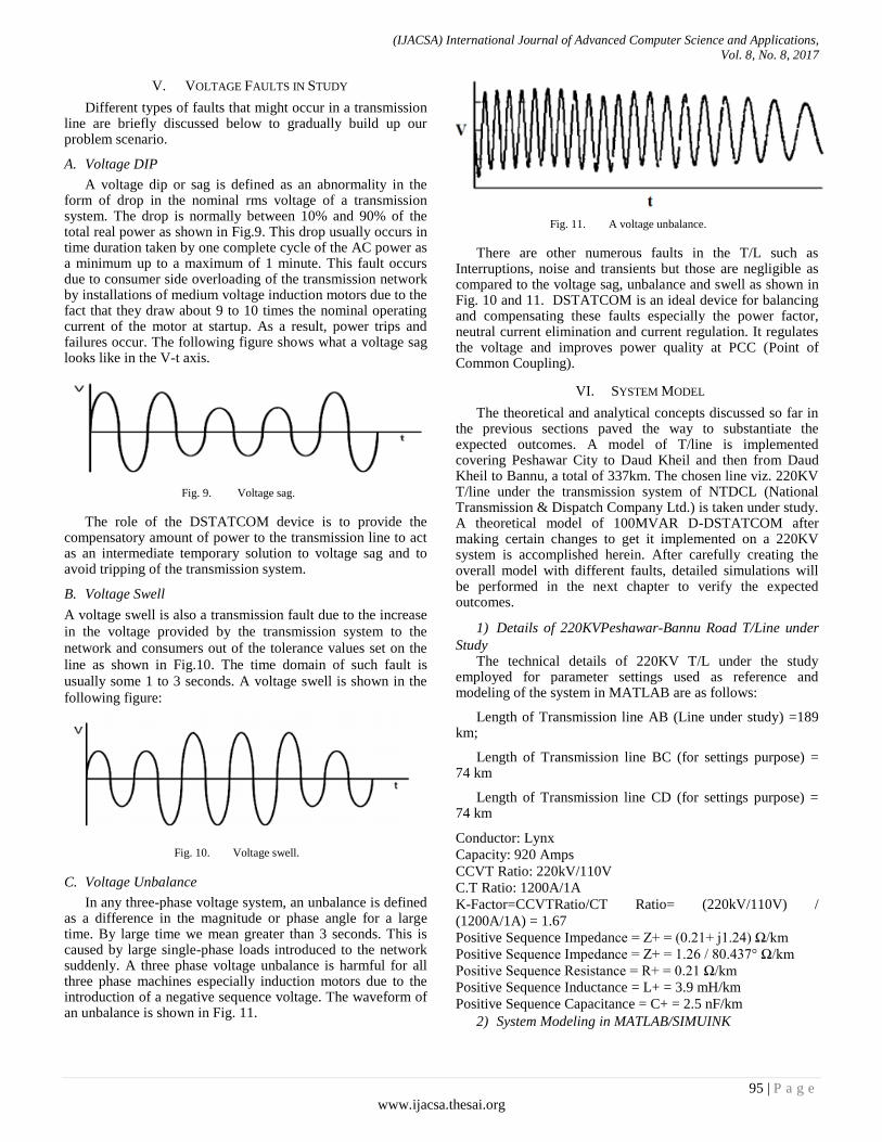
V. VOLTAGE FAULTS IN STUDY
Different types of faults that might occur in a transmission line are briefly discussed below to gradually build up our problem scenario.
A. Voltage DIP
A voltage dip or sag is defined as an abnormality in the form of drop in the nominal rms voltage of a transmission system. The drop is normally between 10% and 90% of the total real power as shown in Fig.9. This drop usually occurs in time duration taken by one complete cycle of the AC power as a minimum up to a maximum of 1 minute. This fault occurs due to consumer side overloading of the transmission network by installations of medium voltage induction motors due to the fact that they draw about 9 to 10 times the nominal operating current of the motor at startup. As a result, power trips and failures occur. The following figure shows what a voltage sag looks like in the V-t axis.
Fig. 9. Voltage sag.
The role of the DSTATCOM device is to provide the compensatory amount of power to the transmission line to act as an intermediate temporary solution to voltage sag and to avoid tripping of the transmission system.
B. Voltage Swell
A voltage swell is also a transmission fault due to the increase
in the voltage provided by the transmission system to the
network and consumers out of the tolerance values set on the
line as shown in Fig.10. The time domain of such fault is
usually some 1 to 3 seconds. A voltage swell is shown in the
following figure:
Fig. 10. Voltage swell.
C. Voltage Unbalance
In any three-phase voltage system, an unbalance is defined as a difference in the magnitude or phase angle for a large time. By large time we mean greater than 3 seconds. This is caused by large single-phase loads introduced to the network suddenly. A three phase voltage unbalance is harmful for all three phase machines especially induction motors due to the introduction of a negative sequence voltage. The waveform of an unbalance is shown in Fig. 11.
Fig. 11. A voltage unbalance.
There are other numerous faults in the T/L such as Interruptions, noise and transients but those are negligible as compared to the voltage sag, unbalance and swell as shown in Fig. 10 and 11. DSTATCOM is an ideal device for balancing and compensating these faults especially the power factor, neutral current elimination and current regulation. It regulates the voltage and improves power quality at PCC (Point of Common Coupling).
VI. SYSTEM MODEL
The theoretical and analytical concepts discussed so far in the previous sections paved the way to substantiate the expected outcomes. A model of T/line is implemented covering Peshawar City to Daud Kheil and then from Daud Kheil to Bannu, a total of 337km. The chosen line viz. 220KV T/line under the transmission system of NTDCL (National Transmission & Dispatch Company Ltd.) is taken under study. A theoretical model of 100MVAR D-DSTATCOM after making certain changes to get it implemented on a 220KV system is accomplished herein. After carefully creating the overall model with different faults, detailed simulations will be performed in the next chapter to verify the expected outcomes.
1) Details of 220KVPeshawar-Bannu Road T/Line under
Study The technical details of 220KV T/L under the study
employed for parameter settings used as reference and modeling of the system in MATLAB are as follows:
Length of Transmission line AB (Line under study) =189 km;
Length of Transmission line BC (for settings purpose) = 74 km
Length of Transmission line CD (for settings purpose) = 74 km
Conductor: Lynx
Capacity: 920 Amps
CCVT Ratio: 220kV/110V
C.T Ratio: 1200A/1A
K-Factor=CCVTRatio/CT Ratio= (220kV/110V) /
(1200A/1A) = 1.67
Positive Sequence Impedance = Z+ = (0.21+ j1.24) Ω/km
Positive Sequence Impedance = Z+ = 1.26 / 80.437° Ω/km
Positive Sequence Resistance = R+ = 0.21 Ω/km
Positive Sequence Inductance = L+ = 3.9 mH/km
Positive Sequence Capacitance = C+ = 2.5 nF/km
2) System Modeling in MATLAB/SIMUINK

(IJACSA) International Journal of Advanced Computer Science and Applications,
Vol. 8, No. 8, 2017
96 | P a g e
www.ijacsa.thesai.org
The simplest model of the system under study is designed in Simulink 2016 and is shown below in Fig. 12. The model consists of a 220KV Peshawar to Daud Khel and then Bannu T/Line using Π-model with aforementioned technical details emanating from 500KV Grid Station NTDCL, ShahiBagh and terminating at 220KV Grid station at Peshawar City. The distance relay is located at the end near Bannu Grid Station for essentially detecting any faults whatsoever. The 111MVAR D-DSTATCOM is situated at the center of the line to compensate the voltage to maintain the system voltage by injecting or absorbing reactive power. The Fault Selector is used to involve various types of faults at different locations of the line to observe the behavior of impedance relay with and without DSTATCOM.
A Distribution Static Synchronous Compensator (D-DSTATCOM) is used to regulate voltage on a 222-kV distribution network as shown. Two feeders, namely, Peshawar to Daud Khel 189 km and Daud Khel to Bannu and 148 km) transmit power to loads connected at buses B2 and B3. The 220-V load connected to bus B3 through a 222kV/220V transformer represents a water motor drawing a large amount of power from the source. The load power factor stays at 0.9 for the setup.
The D-DSTATCOM regulates bus B3 voltage by absorbing or generating reactive power. This reactive power transfer is done through the leakage reactance of the coupling transformer by generating a secondary voltage in phase with the primary voltage (network side).
The D-DSTATCOM consists of the following components:
Voltage Source Converter,
Energy Storage,
L-C Passive Filter,
Control Block, and
Coupling Transformer.
3) Voltage Source Model A VSC converts the DC voltage across storage device into
a three phase AC output voltage wave. It can be a 3-phase-3-wire or 3-phase-4-wire. The VSC is shown in Fig. 12.
4) Energy Storage The DC Storage is essentially a capacitor of 10,000 Farads
value. Two level conversions are used to convert the DC source to an equivalent 3 phase AC voltage.
5) LC Passive filter LC filters as shown below are utilized to compensate for
the harmonic distortion generated on the line as shown in Fig. 13. The use is necessary for matching the output impedance of the line.
Fig. 12. VSC D-DSTATCOM, 2-level conversion using IGBTs.
Fig. 13. RL Branches for harmonics distortion compensation.
6) Coupling Transformer The output from the D-DSTATCOM is linked with that of
the main lines via coupling transformers.
7) Control Block The control block detects faults, voltage sags and swells,
generates trigger pulses for the PWM inverter on occurrence of faults and stops them after event of fault has cleared. The control block is designed on the basis of DQO theory.
D-DSTATCOM working is illustrated in Fig. 14.

(IJACSA) International Journal of Advanced Computer Science and Applications,
Vol. 8, No. 8, 2017
97 | P a g e
www.ijacsa.thesai.org
Fig. 14. D-DSTATCOM working illustration.
The voltage generated is injected at the targeted T/L according to the fault type so that the load supply is not affected.
VII. SIMULATION RESULTS AND DISCUSSION
After detailed modeling of the system in MatLab/Simulink under study in the previous chapter, this chapter presents the results obtained after comprehensive simulations by introducing various faults such as sag and unbalance when an induction motor is started, and evaluating the performance of T/line protection with and in the absence of D-DSTATCOM. The simulations are carried out by creating faults at a specified location in the transmission line and the follow up of the DSTATCOM is observed. Based on the simulation results, conclusions about deviations in the performance characteristics of T/Line protection with mid-point compensating D-DSTATCOM and other important results are presented. By analyzing these deviations, the recommendations to improve the discrepancies are discussed as closing remarks.
A. Simulation Results With 3-ф Faults
Consider the modeled system, a 3-Ф fault is created after 0.2 seconds at various locations along the T/line length and behavior of distance protection is observed for the cases with and in the absence of DSTATCOM at the mid-point. The voltage and current signals before and after fault are shown in Fig. 5. The fault is introduced at 60% (202km) of total line length (337km).
B. Results
Fault has been introduced at start of simulation. The fault is modeled to simulate the behavior of a medium Voltage industrial induction motor being started. As the motor is expected to withdraw a large amount of power, the waveform of the transmission line voltage is introduced with a sag and then an unbalance. The behavior of the system can be seen as follows:
Fig. 15. Va per unit of the 3-phase T/L with current in Blue color.
In Fig. 15, we see the Voltage waveform of the transmission lines when no fault is introduced on it. It is a normal sinusoidal waveform in harmony with the current transmission.
Next a voltage sag is introduced in the system. Due to a single-phase inductive load with high current withdrawal, the waveform becomes distorted and a sag at 0.05 seconds is introduced as can be observed in the following figure (Fig. 16):
Fig. 16. Voltage Sag as a result of Inductive load.
Also observe that in this figure, we have taken current as unavailable or scarce, and the compensator has to complete the requirement for the given loads in the form of reactive power and current.
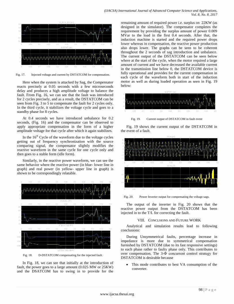
The reactive compensated power introduced by the DSTATCOM in the form of Voltage can be seen in Fig. 17.
(IJACSA) International Journal of Advanced Computer Science and Applications,
Vol. 8, No. 8, 2017
98 | P a g e
www.ijacsa.thesai.org
Fig. 17. Injected voltage and current by DSTATCOM for compensation.
Here when the system is attacked by Sag, the Compensator reacts precisely at 0.05 seconds with a few microseconds delay and produces a high amplitude voltage to balance the fault. From Fig. 16, we can see that the fault was introduced for 2 cycles precisely, and as a result, the DSTATCOM can be seen from Fig. 3 to 5 to compensate the fault for 2 cycles only. In the third cycle, it stabilizes the voltage cycle and goes to a standby phase for 8 cycles.
At 0.4 seconds we have introduced unbalance for 0.2 seconds, (Fig. 16) and the compensator can be observed to apply appropriate compensation in the form of a higher amplitude voltage for that cycle after which it again stabilizes.
In the 16th
Cycle of the waveform due to the voltage cycles getting out of frequency synchronization with the source comparing signal, the compensator slightly modifies the reactive waveform in the same cycle for one cycle only and then goes to a stable form (idle form).
Similarly, in the reactive power waveform, we can see the same behavior where the reactive power (in blue- lower line in graph) and real power (in yellow- upper line in graph) is shown to be correspondingly relatable.
Fig. 18. D-DSTATCOM compensating for the injected fault.
In Fig. 18, we can see that initially at the introduction of fault, the power goes to a large amount (0.025 MW or 25KW) and the DSATCOM has to swing in to provide for the
remaining amount of required power i.e. surplus on 22KW (as designed in the simulator). The compensator completes the requirement by providing the surplus amount of power 0.009 MVar to the load in the first 0.4 seconds. After that, the induction machine is started and the required power drops lower whereas in compensation, the reactive power production also drops lower. The graphs can be seen to be coherent throughout the 2 seconds of sag introduction and unbalance. The current output of the DSTATCOM can be seen below where at the start of the cycle, when the motor required a large amount of current and we have decreased the available current in the transmission line below 0, the DSTATCOM device is fully operational and provides for the current compensation in each cycle of the waveform both in start of the induction motor as well as during loaded operation as seen in Fig. 19 below:
Fig. 19. Current output of DSTATCOM in fault event
Fig. 19 shows the current output of the DSTATCOM in the event of a fault.
Fig. 20. Power Inverter output for compensating the voltage sags.
The output of the inverter in Fig. 20 shows that the reactive power output from the DSTATCOM has been injected in to the T/L for correcting the fault.
VIII. CONCLSIONS AND FUTURE WORK
Analytical and simulation results lead to following conclusions:
During Unsymmetrical faults, percentage increase in impedance is more due to symmetrical compensation furnished by DSTATCOM (due to its fast responsive settings) to each phase rather to faulty phase only. This contributes to over compensation. The 3-Ф concurrent control strategy for DSTATCOM is desirable because
This mode contributes to best VA consumption of the converter.

(IJACSA) International Journal of Advanced Computer Science and Applications,
Vol. 8, No. 8, 2017
99 | P a g e
www.ijacsa.thesai.org
Harmonic generation is the lowest in this mode.
Response time is immediate [13].
The major parameters affecting the performance of relay are:
Fault Location
Distance of fault after location of compensating device
Level of compensation furnished by DSTATCOM
Type of fault.
Simulation also shows that the DSTATCOM is an effective device in compensating for the various types of faults in the transmission line.
The system cannot compensate 100% of the voltage during sag, but the compensation values are in nominal ranges and are best for practical installations and deployments.
The current implemented scheme of Distance Protection for 220KV Peshawar to Bannu T/L is “Basic Distance Protection” which must be revised before the proposed installation of DSTATCOM.
The scheme may be revised to Communication Aided Distance Protection.
Due to the use of IGBTs in the Distribution Static Compensators in the Dynamic Application, there are bound to be many harmonics and distortions, hence a suitable type of filter can be used to filter the noise. For this purpose, LCL filter can be used and introduced in the control structure of the DSTATCOM for further research.
Since DSTATCOM devices use PWM signals, a better alternative can be SWPWM (Sine Wave PWM) where the efficiency of the converted voltage and its power factor increases and a more quality voltage signal with less distortions and harmonics is produced. This will affect the devices performance in a positive way.
ACKNOWLEDGEMENTS
Authors would like to acknowledge the financial support provided by the CECOS University of IT and Emerging Sciences Peshawar Pakistan.
REFERENCES
[1] Mr. Ajaysing, T. Chandan, K. Venkata Rama Mohan, Santhosh Kampelli, Arvind R. Singh, “Advance Distance Protection of Transmission Line in Presence of Shunt Compensator” International Research Journal of Engineering and Technology (IRJET) June 2015.
[2] Z. Moravey, M. Pazoki and M. Khederazahe, “Impact of UPFC on Power Swing Characteristic and Distance relay Behavior” IEEE Transactions on Power Delivery, Vol. 29, No. 1, February 2014.
[3] Naresh Patnana, Swamynadha Sree Venkata Ramana Chakkirala, “Effect of FACTS Controllers on Impedance Relay Characteristics” International Conference on Engineering Trends and Science & Humanities (ICETSH) 2015.
[4] Mohamed Elsamaly, Sherif Omar Faried and Tarlochan Sidhu, “Impact of Midpoint DSTATCOM on Generator Loss of Excitation Protection” IEEE TRANSACTIONS ON POWER DELIVERY, VOL 29, No. 2, APRIL 2014.
[5] Danna Hemasunder, Mohan Thakre, V.S Kale, “Impact of DSTATCOM on Distance Relay-Modeling and Simulation using PSCAD/EMTDC” IEEE Students Conference on Electrical, Electronics and Computer Sciences 2014.
[6] Gorakshanath Abande, M.F.A.R Satarkar, Mohan Thakre, Dr. V.S Kale, Ganesh Patil, “Impact Analysis of DSTATCOM on Distance Relay” International Journal of Innovative Research in Science, Engineering and Technology, Volume 3, Special Issue 3, March 2014.
[7] Mohammed Zellague, “A Comparative Study of Impact Series FACTS Devices on Distance Relay in 400KV Transmission Line” Journal of Electrical and Electronics Engineering (JEEE).
[8] Mohammed Zellague, Abdelaziz Chaghi, “Impact of TCSC on Distance Protection Setting Based Modified Particle Sworm Optimization Technique” IJISA Vol. 5, May 2013.
[9] Gaber El-Saady, Rashad M. Kamel, Essam M. Ali, “Error Analysis in Distance Relay Readings with presence of FACTS Devices” Innovative System Design and Engineering, Vol. 4, No. 14, 2013.
[10] Mohammed Zellague, Abdelaziz Chaghi, “Impact of Apparent Reactance injected by TCSR on Distance Relay in Presence of Phase to Earth Fault” Power Engineering and Electrical Engineering Volume 11, Number 3, 2013.
[11] Mojtaba Khaderzadeh and Amir Gharbani, “Impact of VSC-Based Multiline FACTS Controllers on Distance Protection of Transmission Line”
[12] Sankara Subramanian, Anthony Perks, Sarath B Tennakoon, Noel Shammas, “Protection Issues Associated With The Proliferation Of Static Synchronous Compensator (DSTATCOM) Type Facts Devices In Power Systems”.
[13] Wen-Hao Zhang, Seung-Jae Lee, Myeon-Song Choi and Shigeto Oda, “Considerations on Distance Relay Setting for Transmission Line with DSTATCOM” IEEE 2010.
[14] Mohammad Javad Farah, Behrooz Vahidi, Hossein Askarian Abyaneh, “Effect of FACTS Devices on Measured Impedance by Distance Relay” SINTE 8, 2013.
[15] Yongan Deng, “Reative Power Compensation of Transmission Lines” Concordia University.
[16] Narain G. Hingorani, Laszlo Gyugyi, “Understanding FACTS” IEEE Power Engineering Society.
[17] Sanaullah Ahmad, Sana Sardar, Azzam ul Assar, Fazal Wahab Karam. “Reliability Analysis of Distribution System using ETAP" International Journal of Computer Science and Information Security 15.3 (2017).
[18] Xunchi Wu, “Reactive Power Compensation Based on FACTs Devices” Columbia University.
[19] Aamir Aman, Sanaullah Ahmad, Khalid Mahmood, Designing and Strategic Cost Estimation of Stand-Alone Hybrid Renewable Energy System, 4th International Conference on Energy, Environment and Sustainable Development 2016.
[20] R. Mohan Mathur, Rajiv K. Varma, “Thyristor Based FACTS Controllers for Electrical Transmission Systems” IEEE Press.
[21] Tariq Masood, R.K. Aggarwal, S.A. Qureshi, R.A.J Khan, “DSTATCOM Model against SVC Control Model Performance Analysis Techniques”.
[22] Festo Didactic Canada, Courseware sample on “Static Synchronous Compensator (DSTATCOM)” Library and Archives Canada 12/2014.