Performance Evaluation of the Quadrics Interconnection Network
18
Cluster Computing 6, 125–142, 2003 2003 Kluwer Academic Publishers. Manufactured in The Netherlands. Performance Evaluation of the Quadrics Interconnection Network FABRIZIO PETRINI ∗ , EITAN FRACHTENBERG and ADOLFY HOISIE CCS-3 Modeling, Algorithms and Informatics, Computer and Computational Sciences Division, Los Alamos National Laboratory, USA SALVADOR COLL CCS-3 Modeling, Algorithms and Informatics, Computer and Computational Sciences Division, Los Alamos National Laboratory, USA, and Electronic Engineering Department, Technical University of Valencia, Spain Abstract. In this paper we present an in-depth description of the Quadrics interconnection network (QsNET) and an experimental perfor- mance evaluation on a 64-node AlphaServer cluster. We explore several performance dimensions and scaling properties of the network by using a collection of benchmarks, based on different traffic patterns. Experiments with permutation patterns and uniform traffic are conducted to illustrate the basic characteristics of the interconnect under conditions commonly created by parallel scientific applications. Moreover, the behavior of the QsNET under I/O traffic, and the influence of the placement of the I/O servers are analyzed. The effects of using dedicated I/O nodes or shared I/O nodes are also exposed. In addition, we evaluate how background I/O traffic interferes with other parallel applications running concurrently. The experimental results indicate that the QsNET provides excellent performance in most cases, with excellent con- tention resolution mechanisms. Some important guidelines for applications and I/O servers mapping on large-scale clusters are also given. Keywords: interconnection networks, performance evaluation, user-level communication, operating system bypass 1. Introduction Some interconnect technologies used in high-performance computers include Gigabit Ethernet [22], Giganet [25], SCI [7], Myrinet [1] and GSN (HIPPI 6400) [24]. 1 Each one provides a different level of programmability, raw per- formance and integration with the operating-system. InfiniBand [8] has been recently proposed as a standard for communication between processing nodes and I/O devices as well as for interprocessor communication, offering an inte- grated view of computing, networking and storage technolo- gies. The InfiniBand architecture is based on a switch inter- connect technology with high speed point-to-point links and offers support for Quality of Service (QoS), fault-tolerance, remote direct memory access, etc. The Quadrics interconnection network (QsNET) provides a number of innovative design issues, some of which are very similar to those defined by the InfiniBand specification. Some of these salient aspects are the presence of a programmable processor in the network interface that allows the implemen- tation of intelligent communication protocols, fault-tolerance, and remote direct memory access. In addition, the QsNET integrates the local virtual memory into a distributed virtual shared memory. The Quadrics network is currently utilized in some of the largest parallel systems in the world, mainly con- necting Compaq Alpha-based servers, but increasingly other compute platforms too. The performance of interconnection networks and, in par- ticular, switch-based wormhole networks has been exten- sively analyzed by simulation in the literature [2,11]. Since ∗ Corresponding author. E-mail: [email protected] performance is strongly influenced by the load, it is very im- portant to evaluate the QsNET under more varied traffic pat- terns to get a complete view of the network behavior. The patterns considered in this work are representative of real sci- entific applications in use at Los Alamos National Labora- tory. One example of workload analysis is presented in [9] for SAGE (SAIC’s Adaptive Grid Eulerian hydrocode), an important ASCI application. In [13] we analyzed the QsNET performance under spe- cific load conditions to obtain the “peak performance” of the network and a baseline for further studies. In this paper we analyze the behavior of the Quadrics interconnect with a much broader set of workload conditions. Since the effi- cient integration of the network with the I/O is a key factor to efficiently exploit the power of high-performance parallel computers, we also address the evaluation of the networking and the I/O integration in the QsNET. The test bed for the network evaluation was a 64-node QsNET-based AlphaServer ES40 cluster. The performance effects in the network are explained in terms of hardware pa- rameters, flow control and congestion resolution. The paper introduces a number of novel concepts in analyzing network performance, such as the congestion matrix in section 5.4. The results of the analysis in this work have powerful and direct practical implications, for example, related to the I/O node mapping and application distribution. The study of the hardware and software primitives used to implement multi- cast communication and the impact of the network perfor- mance on the user applications are outside the scope of the paper and can be found in [14] and [9], respectively. The rest of this paper is organized as follows. Section 2 gives a comprehensive presentation of the network hardware
Transcript of Performance Evaluation of the Quadrics Interconnection Network

Cluster Computing 6, 125–142, 2003 2003 Kluwer Academic Publishers. Manufactured in The Netherlands.
Performance Evaluation of the Quadrics Interconnection Network
FABRIZIO PETRINI ∗, EITAN FRACHTENBERG and ADOLFY HOISIECCS-3 Modeling, Algorithms and Informatics, Computer and Computational Sciences Division, Los Alamos National Laboratory, USA
SALVADOR COLLCCS-3 Modeling, Algorithms and Informatics, Computer and Computational Sciences Division, Los Alamos National Laboratory, USA, and
Electronic Engineering Department, Technical University of Valencia, Spain
Abstract. In this paper we present an in-depth description of the Quadrics interconnection network (QsNET) and an experimental perfor-mance evaluation on a 64-node AlphaServer cluster. We explore several performance dimensions and scaling properties of the network byusing a collection of benchmarks, based on different traffic patterns. Experiments with permutation patterns and uniform traffic are conductedto illustrate the basic characteristics of the interconnect under conditions commonly created by parallel scientific applications. Moreover, thebehavior of the QsNET under I/O traffic, and the influence of the placement of the I/O servers are analyzed. The effects of using dedicatedI/O nodes or shared I/O nodes are also exposed. In addition, we evaluate how background I/O traffic interferes with other parallel applicationsrunning concurrently. The experimental results indicate that the QsNET provides excellent performance in most cases, with excellent con-tention resolution mechanisms. Some important guidelines for applications and I/O servers mapping on large-scale clusters are also given.
Keywords: interconnection networks, performance evaluation, user-level communication, operating system bypass
1. Introduction
Some interconnect technologies used in high-performancecomputers include Gigabit Ethernet [22], Giganet [25],SCI [7], Myrinet [1] and GSN (HIPPI 6400) [24].1 Eachone provides a different level of programmability, raw per-formance and integration with the operating-system.
InfiniBand [8] has been recently proposed as a standard forcommunication between processing nodes and I/O devices aswell as for interprocessor communication, offering an inte-grated view of computing, networking and storage technolo-gies. The InfiniBand architecture is based on a switch inter-connect technology with high speed point-to-point links andoffers support for Quality of Service (QoS), fault-tolerance,remote direct memory access, etc.
The Quadrics interconnection network (QsNET) providesa number of innovative design issues, some of which are verysimilar to those defined by the InfiniBand specification. Someof these salient aspects are the presence of a programmableprocessor in the network interface that allows the implemen-tation of intelligent communication protocols, fault-tolerance,and remote direct memory access. In addition, the QsNETintegrates the local virtual memory into a distributed virtualshared memory. The Quadrics network is currently utilized insome of the largest parallel systems in the world, mainly con-necting Compaq Alpha-based servers, but increasingly othercompute platforms too.
The performance of interconnection networks and, in par-ticular, switch-based wormhole networks has been exten-sively analyzed by simulation in the literature [2,11]. Since
∗ Corresponding author.E-mail: [email protected]
performance is strongly influenced by the load, it is very im-portant to evaluate the QsNET under more varied traffic pat-terns to get a complete view of the network behavior. Thepatterns considered in this work are representative of real sci-entific applications in use at Los Alamos National Labora-tory. One example of workload analysis is presented in [9]for SAGE (SAIC’s Adaptive Grid Eulerian hydrocode), animportant ASCI application.
In [13] we analyzed the QsNET performance under spe-cific load conditions to obtain the “peak performance” of thenetwork and a baseline for further studies. In this paperwe analyze the behavior of the Quadrics interconnect witha much broader set of workload conditions. Since the effi-cient integration of the network with the I/O is a key factorto efficiently exploit the power of high-performance parallelcomputers, we also address the evaluation of the networkingand the I/O integration in the QsNET.
The test bed for the network evaluation was a 64-nodeQsNET-based AlphaServer ES40 cluster. The performanceeffects in the network are explained in terms of hardware pa-rameters, flow control and congestion resolution. The paperintroduces a number of novel concepts in analyzing networkperformance, such as the congestion matrix in section 5.4.The results of the analysis in this work have powerful anddirect practical implications, for example, related to the I/Onode mapping and application distribution. The study of thehardware and software primitives used to implement multi-cast communication and the impact of the network perfor-mance on the user applications are outside the scope of thepaper and can be found in [14] and [9], respectively.
The rest of this paper is organized as follows. Section 2gives a comprehensive presentation of the network hardware

126 PETRINI ET AL.
Figure 1. Elan functional units.
building blocks. Section 3 discusses the hierarchy of com-munication libraries. In section 4 a description of the exper-imental methodology is given, while section 5 presents theexperimental results and performance analysis. Finally, someconcluding remarks are drawn in section 6.
2. The QsNET
The QsNET is based on two building blocks, a programmablenetwork interface called Elan [20] and a low-latency high-bandwidth communication switch called Elite [21]. Elites canbe interconnected in a fat-tree topology [10]. The networkhas several layers of communication libraries which providetrade-offs between performance and ease of use. Other im-portant features are hardware support for collective commu-nication and fault-tolerance.
2.1. Elan
The Elan2 network interface links the high-performance,multi-stage Quadrics network to a processing node contain-ing one or more CPUs. In addition to generating and accept-ing packets to and from the network, the Elan also providessubstantial local processing power to implement high-levelmessage-passing protocols such as MPI. The internal func-
tional structure of the Elan, shown in figure 1, centers aroundtwo primary processing engines: the microcode processor andthe thread processor.
The 32-bit microcode processor supports four separatethreads of execution, where each thread can independentlyissue pipelined memory requests to the memory system. Upto eight requests can be outstanding at any given time. Thescheduling for the microcode processor is lightweight, en-abling a thread to wake up, schedule a new memory accesson the result of a previous memory access, and then go backto sleep in as few as two system-clock cycles.
The four microcode threads are described below: (1) In-putter thread: Handles input transactions from the net-work. (2) DMA thread: Generates DMA packets to bewritten to the network, prioritizes outstanding DMAs, andtime-slices large DMAs so that small DMAs are not ad-versely blocked. (3) Processor-scheduling thread: Prioritizesand controls the scheduling and descheduling of the threadprocessor. (4) Command-processor thread: Handles opera-tions requested by the host processor at user level.
The thread processor is a 32-bit RISC processor used to aidthe implementation of higher-level messaging libraries with-out explicit intervention from the main CPU. In order to bet-ter support such an implementation, the thread processor’s in-struction set was augmented with extra instructions that con-

PERFORMANCE EVALUATION OF THE QUADRICS INTERCONNECTION NETWORK 127
struct network packets, manipulate events, efficiently sched-ule threads, and block-save and restore a thread’s state whenscheduling.
The Elan contains routing tables that translate every virtualprocess number into a sequence of tags that determine thenetwork route. Several routing tables can be loaded in orderto have different routing strategies. The link logic transmitsand receives data from the network and outputs 9 bits and aclock signal on each half of the clock cycle. The flit encodingscheme allows data and command tokens to be interleaved onthe link and prevents a corrupted data word being interpretedas a token or a token being interpreted as another token. Eachlink provides buffer space for two virtual channels with a 128-entry, 16-bit FIFO RAM for flow control.
2.2. Elite
The other building block of the QsNET is the Elite switch.The Elite provides the following features: (1) 8 bidirectionallinks supporting two virtual channels in each direction, (2) aninternal 16 × 8 full crossbar switch,3 (3) a nominal transmis-sion bandwidth of 400 MB/s on each link direction and a flowthrough latency of 35 ns, (4) packet error detection and recov-ery, with routing and data transactions CRC protected, (5) twopriority levels combined with an aging mechanism to ensurea fair delivery of packets in the same priority level, (6) hard-ware support for broadcasts, and (7) adaptive routing.
The Elite switches are interconnected in a quaternary fat-tree topology, which belongs to the more general class of thek-ary n-trees [16,17]. A quaternary fat-tree of dimension n iscomposed of 4n processing nodes and n × 4n−1 switches in-terconnected as a delta network, and can be recursively builtby connecting 4 quaternary fat trees of dimension n−1. Qua-ternary fat trees of dimension 1, 2 and 3 are shown in figure 2.
2.2.1. Packet routing and flow controlEach user- and system-level message is chunked in a sequenceof packets by the Elan. An Elan packet contains three maincomponents. The packet starts with the (1) routing informa-tion, that determines how the packet will reach the destina-tion. This information is followed by (2) one or more transac-tions consisting of some header information, a remote mem-ory address, the context identifier and a chunk of data, whichcan be up to 64 bytes in the current implementation. Thepacket is terminated by (3) an end of packet (EOF) token, asshown in figure 3.
Transactions fall into two categories: write block transac-tions and non-write block transactions.
The purpose of a write block transaction is to write a blockof data from the source node to the destination node, usingthe destination address contained in the transaction immedi-ately before the data. A DMA operation is implemented asa sequence of write block transactions, partitioned into oneor more packets (a packet normally contains 5 write blocktransactions of 64 bytes each, for a total of 320 bytes of datapayload per packet).
Figure 2. 4-ary n-trees of dimension 1, 2 and 3.
Figure 3. Packet transaction format.
The non-write block transactions implement a familyof relatively low level communication and synchronizationprimitives. For example, non-write block transactions canatomically perform remote test-and-write or fetch-and-addand return the result of the remote operation to the source, andcan be used as building blocks for more sophisticated distrib-uted algorithms.
Elite networks are source routed. The routing informationis attached to the header before injecting the packet into thenetwork and is composed by a sequence of Elite link tags.As the packet moves inside the network, each Elite removesthe first routing tag from the header, and forwards the packetto the next Elite in the route or to the final destination. Therouting tag can identify either a single output link or a groupof adjacent links.

128 PETRINI ET AL.
The transmission of each packet is pipelined into the net-work using wormhole flow control. At link level, each packetis partitioned in smaller units called flits (flow control dig-its) [3] of 16 bits. The header flit opens a circuit betweensource and destination, and this path stays in place until thedestination sends an acknowledgment to the source. At thispoint, the circuit is closed by sending and End Of Packet(EOP) token. It is worth noting that both acknowledgmentand EOP can be tagged to communicate control information.So, for example, the destination can notify the successfulcompletion of a remote non-write block transaction withoutexplicitly sending an extra packet.
Minimal routing between any pair nodes can be accom-plished by sending the message to one of the nearest com-mon ancestors and from there to the destination. That is, eachpacket experiences two routing phases, an adaptive ascend-ing phase to get to a nearest common ancestor, followed by adeterministic descending phase. The Elite switches can adap-tively route a packet picking the least loaded link.
3. Programming libraries
The Elan network interface can be programmed using severalprogramming libraries [19], as outlined in figure 4. These li-braries trade speed with machine independence and program-mability. Starting from the bottom, Elan3lib is the lowestprogramming level available in user space which allows theaccess to the low level features of the Elan3. At this level,processes in a parallel job can communicate with each otherthrough an abstraction of distributed virtual shared memory.Each process in a parallel job is allocated a virtual process id(VPID) and can map a portion of its address space into theElan. These address spaces, taken in combination, constitutea distributed virtual shared memory. Remote memory (i.e.,memory on another processing node) can be addressed by acombination of a VPID and a virtual address. Since the Elanhas its own MMU, a process can select which part of its ad-dress space should be visible across the network, determinespecific access rights (e.g., write- or read-only) and select theset of potential communication partners.
Elanlib is a higher level layer that frees the programmerfrom the revision-dependent details of the Elan, and extendsElan3lib with point-to-point, tagged message passing primi-tives (called Tagged Message Ports or Tports) and support forcollective communication. Standard communication libraries
Figure 4. Elan3 programming library hierarchy.
as such MPI-2 [5] or Cray Shmem are implemented on top ofElanlib.
3.1. Elan3lib
The Elan3lib library supports a programming environmentwhere groups of cooperating processes can transfer data di-rectly, while protecting process groups from each other inhardware. The communication takes place at user level, withno data copying, bypassing the operating system. The mainfeatures of Elan3lib are: (1) event notification, (2) the mem-ory mapping and allocation scheme and (3) remote DMAtransfers.
3.1.1. Event notificationEvents provide a general purpose mechanism for processes tosynchronize their actions. The mechanism can be used bythreads running on the Elan and processes running on themain processor. Events can be accessed both locally andremotely. Thus, processes can be synchronized across thenetwork, and events can be used to indicate the end of acommunication operation, such as a completion of a remoteDMA. Events are stored in Elan memory, in order to guaran-tee the atomic execution of the synchronization primitives.4
Processes can wait for an event to be triggered by blockingor polling. In addition, an event can be tagged as being ablock copy event. The block copy mechanism works as fol-lows. A block of data in Elan memory is initialized to holda pre-defined value. An equivalent sized block is located inmain memory, and both are in the user’s virtual address space.When the specified event is set, for example, when a DMAtransfer has completed, a block copy takes place. That is, theblock in Elan memory is copied to the block in main memory.The user process polls the block in main memory to checkits value (for example, bringing a copy of the correspondingmemory block into the L2 cache), without having to poll forthis information across the PCI bus. When the value is thesame as that initialized in the source block, the process knowsthat the specified event has happened.
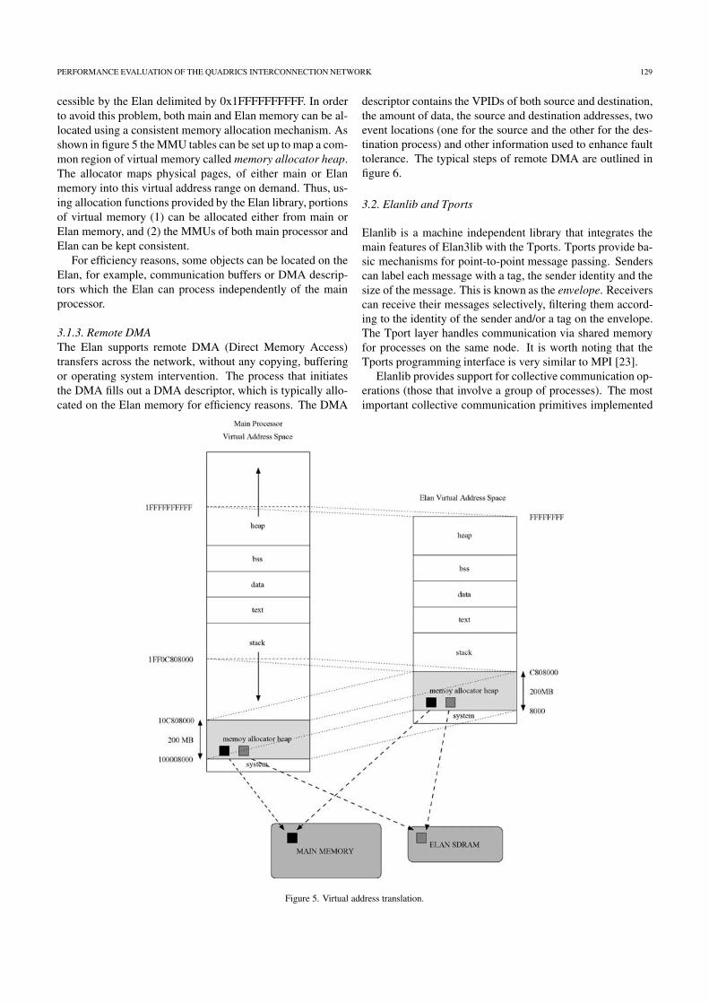
3.1.2. Memory mapping and allocationThe MMU in the Elan can translate between virtual addresseswritten in the format of the main processor (for example,a 64-bit word, big Endian architecture as the AlphaServer)and virtual addresses written in the Elan format (a 32-bitword, little Endian architecture). For a processor with a 32-bit architecture (for example, an Intel Pentium), a one-to-onemapping is all that is required.
In figure 5 the mapping for a 64-bit processor is shown.The 64-bit addresses starting at 0x1FF0C808000 are mappedto Elan’s 32 bit addresses starting at 0xC808000. Thismeans that virtual addresses in the range 0x1FF0C808000to 0x1FFFFFFFFFF can be accessed directly by the mainprocessor while the Elan can access the same memory by us-ing addresses in the range 0xC808000 to 0xFFFFFFFF. In ourexample, the user may allocate main memory using mallocand the process heap may grow outside the region directly ac-
PERFORMANCE EVALUATION OF THE QUADRICS INTERCONNECTION NETWORK 129
cessible by the Elan delimited by 0x1FFFFFFFFFF. In orderto avoid this problem, both main and Elan memory can be al-located using a consistent memory allocation mechanism. Asshown in figure 5 the MMU tables can be set up to map a com-mon region of virtual memory called memory allocator heap.The allocator maps physical pages, of either main or Elanmemory into this virtual address range on demand. Thus, us-ing allocation functions provided by the Elan library, portionsof virtual memory (1) can be allocated either from main orElan memory, and (2) the MMUs of both main processor andElan can be kept consistent.
For efficiency reasons, some objects can be located on theElan, for example, communication buffers or DMA descrip-tors which the Elan can process independently of the mainprocessor.
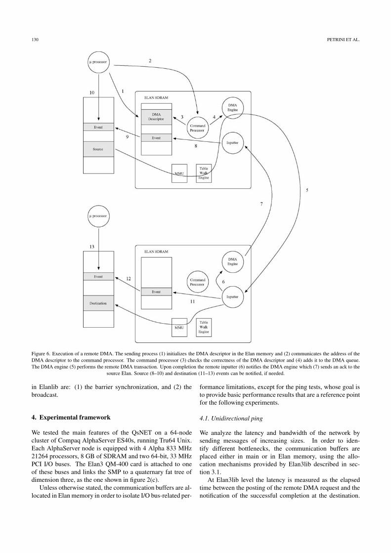
3.1.3. Remote DMAThe Elan supports remote DMA (Direct Memory Access)transfers across the network, without any copying, bufferingor operating system intervention. The process that initiatesthe DMA fills out a DMA descriptor, which is typically allo-cated on the Elan memory for efficiency reasons. The DMA
descriptor contains the VPIDs of both source and destination,the amount of data, the source and destination addresses, twoevent locations (one for the source and the other for the des-tination process) and other information used to enhance faulttolerance. The typical steps of remote DMA are outlined infigure 6.
3.2. Elanlib and Tports
Elanlib is a machine independent library that integrates themain features of Elan3lib with the Tports. Tports provide ba-sic mechanisms for point-to-point message passing. Senderscan label each message with a tag, the sender identity and thesize of the message. This is known as the envelope. Receiverscan receive their messages selectively, filtering them accord-ing to the identity of the sender and/or a tag on the envelope.The Tport layer handles communication via shared memoryfor processes on the same node. It is worth noting that theTports programming interface is very similar to MPI [23].
Elanlib provides support for collective communication op-erations (those that involve a group of processes). The mostimportant collective communication primitives implemented
Figure 5. Virtual address translation.
130 PETRINI ET AL.
Figure 6. Execution of a remote DMA. The sending process (1) initializes the DMA descriptor in the Elan memory and (2) communicates the address of theDMA descriptor to the command processor. The command processor (3) checks the correctness of the DMA descriptor and (4) adds it to the DMA queue.The DMA engine (5) performs the remote DMA transaction. Upon completion the remote inputter (6) notifies the DMA engine which (7) sends an ack to the
source Elan. Source (8–10) and destination (11–13) events can be notified, if needed.
in Elanlib are: (1) the barrier synchronization, and (2) thebroadcast.
4. Experimental framework
We tested the main features of the QsNET on a 64-nodecluster of Compaq AlphaServer ES40s, running Tru64 Unix.Each AlphaServer node is equipped with 4 Alpha 833 MHz21264 processors, 8 GB of SDRAM and two 64-bit, 33 MHzPCI I/O buses. The Elan3 QM-400 card is attached to oneof these buses and links the SMP to a quaternary fat tree ofdimension three, as the one shown in figure 2(c).
Unless otherwise stated, the communication buffers are al-located in Elan memory in order to isolate I/O bus-related per-
formance limitations, except for the ping tests, whose goal isto provide basic performance results that are a reference pointfor the following experiments.
4.1. Unidirectional ping
We analyze the latency and bandwidth of the network bysending messages of increasing sizes. In order to iden-tify different bottlenecks, the communication buffers areplaced either in main or in Elan memory, using the allo-cation mechanisms provided by Elan3lib described in sec-tion 3.1.
At Elan3lib level the latency is measured as the elapsedtime between the posting of the remote DMA request and thenotification of the successful completion at the destination.

PERFORMANCE EVALUATION OF THE QUADRICS INTERCONNECTION NETWORK 131
The unidirectional ping tests for MPI are implemented usingmatching pairs of blocking sends and receives.
4.2. Bidirectional ping
The unidirectional ping experiments can be considered as the“peak performance” of the network. By sending packets inboth directions along the same network path we can exposeseveral types of bottlenecks.
For example, the Elan microcode interleaves four activi-ties, DMA engine, inputter, command processor, and threadprocessor. This test can evaluate how the DMA engine andthe inputter can work with bidirectional traffic. Also the link-level flow control requires the transmission of control infor-mation, which can lead to a degradation of the unidirectionalperformance in the presence of bidirectional traffic. Bidirec-tional traffic is typically generated by permutation patterns inwhich a node is both source and destination.
4.3. Uniform traffic
The uniform traffic is one of the most frequently used trafficpatterns for evaluating the network performance. With thispattern each node randomly selects its destinations. This dis-tribution provides what is likely to be an upper bound on themean internode distance because most computations exhibitsome degree of communication locality [4,9].
4.4. Permutation patterns
These experiments provide information regarding the perfor-mance of the network under communication patterns that takeinto account the behavior of parallel numerical algorithmsusually employed by scientific applications. In these patterns,each node selects a fixed destination for all its transactions.
The permutation patterns tested were:
• Bit-reversal. The node with binary coordinates an−1,
an−2, . . . , a1, a0 communicates with node a0, a1, . . . ,
an−2, an−1.
• Butterfly. The node with binary coordinates an−1,
an−2, . . . , a1, a0, communicates with node a0, an−2, . . . ,
a1, an−1 (swap the most and least significant bits).
• Complement. The node with binary coordinates an−1,
an−2, . . . , a1, a0 communicates with nodean−1, an−2, . . . , a1, a0.
• Matrix transpose. The node with binary coordinatesan−1, an−2, . . . , a1, a0 communicates with nodean/2−1, . . . , a0, an−1, . . . , an/2.
• Perfect-shuffle. The node with binary coordinates an−1,
an−2, . . . , a1, a0 communicates with node an−2,
an−3, . . . , a0, an−1 (rotate left 1 bit).
• Neighbor. Nodes are divided in pairs of adjacent nodes,for example nodes 0 and 1, 2 and 3, n and (n + 1) withn even number, and each node communicates with itsbuddy. This pattern theoretically provides the best perfor-mance achievable because all the traffic is routed through
the first level of switches, therefore avoiding network con-tention.
It is worth noting that all these communication patterns can berouted off-line without conflicts by a fat-tree. So, all the per-formance degradation is introduced by the routing and flowcontrol algorithms [12].
4.5. Hot-spot
Under hot-spot traffic, a set of communication partners try toread from or write into the same memory block. This exper-iment models the behavior of a single I/O server being ac-cessed by multiple clients and provides basic results for bet-ter understanding the network. This localized communicationpattern can lead to a severe form of congestion known as treesaturation [18], which can seriously degrade the overall per-formance of the interconnect.
4.6. Multiple hot-spots
The network traffic generated by a parallel job that is per-forming input/output can be modeled with a collection of hot-spots, where each hot-spot is a node that acts as an I/O server5
and is the target of multiple messages originated by the othernodes. This test has been designed to analyze the behavior ofthe network when one parallel job is performing transactionsover several hot nodes. We address five distinct performancedimensions:
(1) I/O read/write ratio: the ratio between I/O reads andwrites is a number between 0 and 1, with 0 being all readsand 1 all writes.
(2) The inter-arrival time between two I/O messages issuedby a client node can be either uniformly or exponentiallydistributed.
(3) I/O traffic: this parameter defines the access pattern to theI/O nodes. Two patterns have been analyzed:
(a) random I/O, each node performing I/O randomly se-lects its destination for every transaction, and
(b) deterministic I/O, each node uses a fixed destinationfor all its transactions.
(4) I/O node mapping (hot-node mapping): this parameterdefines the placement of the I/O nodes in the cluster. Twoalternatives have been tested:
(a) clustered, I/O nodes located in consecutive nodes atthe higher nodes locations, and
(b) distributed, I/O nodes uniformly distributed throughthe cluster.
(5) Application mapping: defines whether the applicationruns on the I/O nodes (shared I/O) or not (dedicated I/O).
Figure 7 describes the types of I/O and application map-pings used in the experiments with a configuration of 64nodes. In the clustered mapping, 8 I/O nodes are placed in

132 PETRINI ET AL.
Figure 7. I/O and application mappings with 64 nodes and 8 I/O nodes. The arrows highlight the nodes that inject I/O traffic into the network.
Figure 8. I/O and application mappings with 64 nodes and 8 I/O nodes with combined traffic.
the upper part of the network (the dark ones), while the re-maining 56 nodes are dedicated to computation. For this typeof I/O mapping, we consider two types of application map-pings. In the “Shared I/O Mapping” all 64 nodes generate I/Otraffic. In this case, the I/O nodes are both source and des-tination of the I/O traffic. In the “Dedicated I/O Mapping”,only the first 56 nodes inject I/O traffic into the network. TheI/O nodes are only sinks of the I/O traffic, as outlined by thearrow below the first row.
With distributed I/O mapping, shown in the second row offigure 7, the I/O nodes are scattered with a stride of 8 over allthe nodes. In this case we have an I/O node every 8 nodes. Asin the clustered approach, we distinguish the two cases wherethe I/O nodes do and do not inject messages into the network.
4.7. Combined traffic
With this benchmark we study how a parallel job that is exe-cuting I/O traffic can affect the communication performanceof another parallel job that is running concurrently. We per-form the tests by running two parallel jobs in the cluster, eachone using half of the available nodes. The I/O job generatestraffic as described in section 4.6, while the compute job in-jects uniform traffic. We analyze the Cartesian product of sev-eral performance dimensions, which are outlined in figure 8.In particular,
(1) I/O node mapping: we consider clustered (the upper rowof figure 8) and distributed mapping (the lower row of
figure 8). When we have the clustered I/O the position ofboth applications in the cluster may have implications onperformance. For this reason, we distinguish two furthercases. The compute job is mapped onto the lower halfof the network and the job performing I/O on the higherhalf, and the symmetric case. As shown in the upper rowof figure 8, this determines the role (either I/O or com-pute) of the job mapped closer to the I/O nodes.
(2) Application mapping: the two applications running inthis test use half of the available nodes with two differ-ent approaches. If “Shared I/O Mapping” is used eachapplication is mapped to 32 nodes (even if it overlapswith I/O servers). On the other hand, with “DedicatedI/O Mapping” the I/O nodes are dedicated servers andeach application is mapped to 28 nodes.
(3) I/O load: the I/O job can inject messages into the networkwith increasing load.
5. Experimental results
5.1. Unidirectional ping
Figure 9(a) shows the performance of the unidirectional ping.The peak bandwidth of 335 MB/s is reached when both sourceand destination buffers are placed in the Elan memory. Themaximum amount of data payload that can be sent by the cur-rent Elan implementation in a packet is 320 bytes, partitionedin five low-level write-block transactions of 64 bytes. For

PERFORMANCE EVALUATION OF THE QUADRICS INTERCONNECTION NETWORK 133
(a) (b)
Figure 9. Unidirectional ping.
(a) (b)
Figure 10. Bidirectional ping.
this packet format, the overhead is 58 bytes, for the messageheader, CRCs, routing info, etc. This implies that the deliv-ered peak bandwidth is approximately 396 MB/s, or 99% ofthe nominal bandwidth (400 MB/s).
But the asymptotic bandwidth for main memory to mainmemory communication is only 200 MB/s for both Elan3liband MPI. These results show that the PCI interface running at33 MHz is the bottleneck for this type of communication.
Figure 9(b) shows the latency in the range [0 . . . 4 KB].With Elan3lib the basic latency for 0-byte messages is only2.2 µs and is almost constant at 2.4 µs for messages up to64 bytes. We note an increase in the latency at MPI level,compared to the latency at the Elan3lib level, from approx-imately 2 to 5.5 µs. While at Elan3lib level the latency ismostly hardware, MPI needs to run a thread in the Elan micro-processor in order to match the message tags: this introducesthe extra overhead responsible for the higher latency.
5.2. Bidirectional ping
Figure 10(a) shows how the bidirectional bandwidth is de-graded by the PCI bus. When the communication buffers
are in Elan memory, the asymptotic bandwidth is 280 MB/s,a slight performance degradation from the 335 MB/s of theunidirectional ping. With main memory to main memorycommunication the bandwidth drops to 80 MB/s, a perform-ance degradation caused by the PCI bus of the AlphaServer,6
that is not able to efficiently interleave the bidirectional traf-fic. Given this substantial limitation, in the following ex-periments we will place the communication buffers in Elanmemory, in order to inject messages into the network at fullspeed.
5.3. Uniform traffic
The results obtained for the uniform traffic pattern with256 KB messages are shown in figures 11 (a), (b) and (c)for 16, 32 and 64 nodes configurations. The maximum sus-tained bandwidth versus the network size is depicted in fig-ure 11(d).
In the experiments we consider uniform and exponentialdistributions for both message size (identified by the tag S inthe figures) and inter-arrival time (tag T). The results show

134 PETRINI ET AL.
(a) (b)
(c) (d)
Figure 11. Uniform traffic scalability.
that small network configurations are slightly sensitive tothese distributions, providing better results when both mes-sage size and inter-arrival times are uniformly distributed.This performance gap narrows with larger configurations andalmost disappears with 64 nodes.
In figure 11(d) we can see that the network performancedoesn’t scale with the network size. For example, with 64nodes the asymptotic bandwidth is less than 120 MB/s, only42% of the maximum bidirectional bandwidth, which is anupper bound for uniform traffic. This performance degrada-tion is caused by the flow control algorithms. Each packetkeeps an open circuit between source and destination until thepacket is successfully delivered, which increases the probabil-ity of having other packets blocked waiting for an availablepath. This problem is partially alleviated by the two virtualchannels, that offer an escape path when one of the channelsis busy, but they are not enough to guarantee scalability overa large number of nodes.
The results for the maximum bandwidth versus messagesize in figure 12 show that there is a performance penaltywhen the average message size is larger than 16 KB.
Figure 12. Uniform traffic maximum bandwidth.
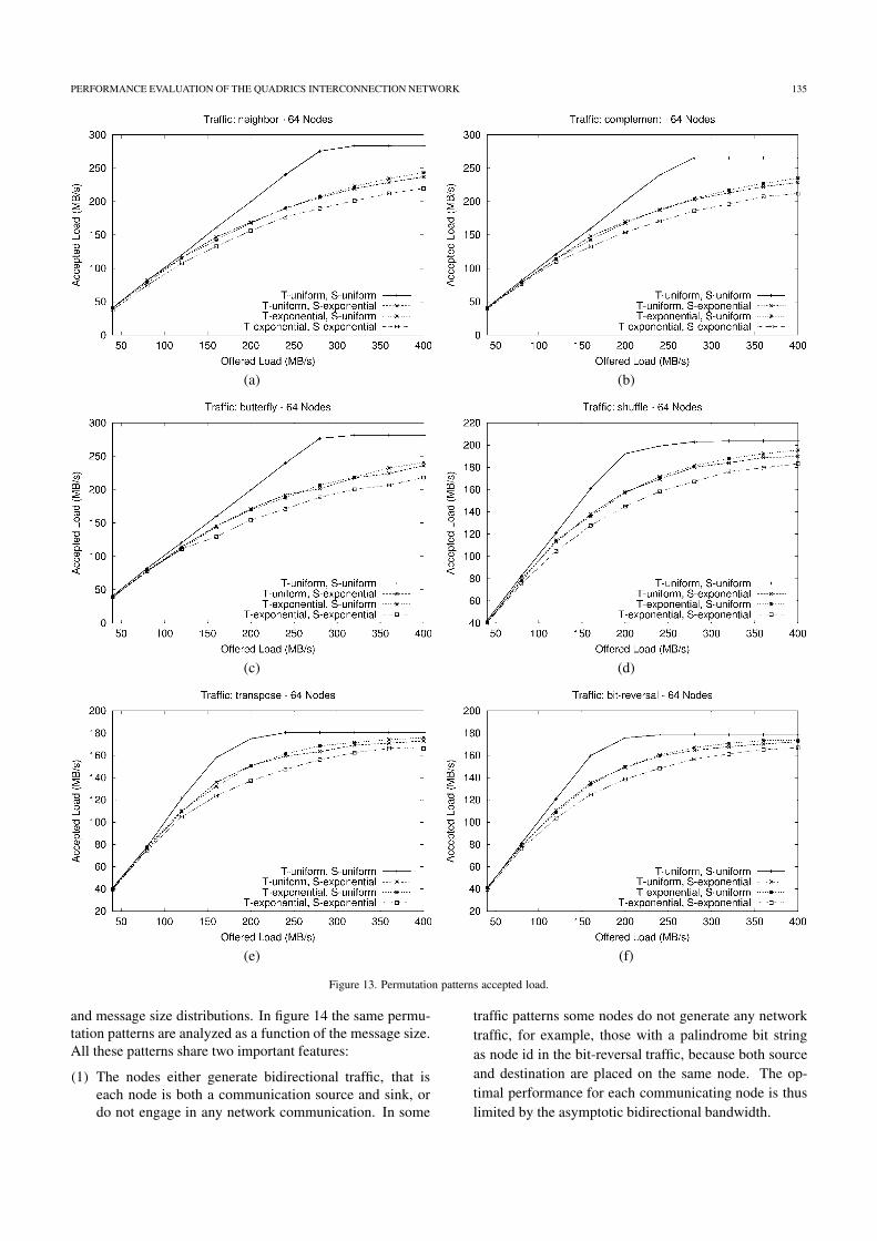
5.4. Permutation patterns
Figure 13 shows the accepted bandwidth versus the offeredbandwidth for all the permutation patterns generated on anetwork configuration with 64 nodes. Average results for256 KB messages are shown for uniform and exponential time
PERFORMANCE EVALUATION OF THE QUADRICS INTERCONNECTION NETWORK 135
(a) (b)
(c) (d)
(e) (f)
Figure 13. Permutation patterns accepted load.
and message size distributions. In figure 14 the same permu-tation patterns are analyzed as a function of the message size.All these patterns share two important features:
(1) The nodes either generate bidirectional traffic, that iseach node is both a communication source and sink, ordo not engage in any network communication. In some
traffic patterns some nodes do not generate any networktraffic, for example, those with a palindrome bit stringas node id in the bit-reversal traffic, because both sourceand destination are placed on the same node. The op-timal performance for each communicating node is thuslimited by the asymptotic bidirectional bandwidth.

136 PETRINI ET AL.
(a) (b)
(c) (d)
(e) (f)
Figure 14. Permutation patterns maximum bandwidth.
(2) All the traffic patterns can be routed by a fat tree in acongestion-free manner by an off-line routing algorithm,so the performance degradation is caused by the on-linerouting and flow control algorithms.
Taking into account the results obtained with the bidirectionalping tests (section 5.2 and figure 10(a)) Elan to Elan com-munication, with asymptotic bandwidth of 280 MB/s), we
have three permutation patterns (neighbor, butterfly, and com-plement) that achieve optimal performance and three otherpatterns (shuffle, transpose, and bit-reversal) that cannot berouted efficiently by the network.
Although neighbor and complement permutations get thesame performance, they generate traffic patterns with widelydifferent topological characteristics. In fact, with the neighbortraffic every destination is two hops away, with each pair of

PERFORMANCE EVALUATION OF THE QUADRICS INTERCONNECTION NETWORK 137
(a)
(b)
Figure 15. Congestion matrices: (a) complement traffic and (b) bit-reversal traffic.
communicating partners connected directly to the same Eliteswitch. This pattern does not generate any traffic that goesabove the first level of switches. On the other hand, withcomplement traffic, every message needs to reach one of thetop-level switches and must be routed along one of the longestpaths (6 hops, in our network configuration). Another inter-esting property of complement traffic is that it can potentiallykeep all the communication links of the network active at thesame time.
The asymptotic performance of shuffle, transpose, and bit-reversal ranges between 165 and 200 MB/s. These traffic pat-terns cannot be handled efficiently by the routing and flowcontrol algorithms. In order to provide more insight into thenetwork behavior, we will use a graphic representation of thenetwork congestion. In figure 15 we can see two congestionmatrices, for the bit-reversal and complement traffic. Thegoal of a congestion matrix is to identify the hot switchesand links, where congestion may arise. The matrix is com-posed of 3 rows with 16 switches each, and represents a qua-ternary fat tree with 64 nodes. Each block has 4 numbers inthe upper side representing the load on the links connecting
the switch to the upper level switches, and 4 numbers in thelower side representing the load on the links connecting to thelower level switches or to the processing nodes. These num-bers represent the sum of the delay experienced by the packetsincoming from the corresponding link, normalized with thevalue of the most loaded link. The number in the center rep-resents the sum of the wait times over all links in the switch,normalized with the value of the most loaded switch. A darkerbackground highlights the congested links or switches.
The congestion matrix of the complement traffic (fig-ure 15(a)) shows that all the delays are evenly distributed forthe switches of the same level. The packets experience an in-creasing delay as they move forward to their destination, from17 units when they enter the first level switch, to 37 unitswhen they enter the second switch, and so on to the most con-gested links from the nodes to the first level of switches onthe way back. From the congestion matrix we can also gatherthat, for this pattern and network configuration, the top levelof switches could be halved, without having a detrimental ef-fect on the overall performance. As shown in [6], fat-treescan efficiently handle this type of communication pattern.

138 PETRINI ET AL.
(a) (b)
Figure 16. Write hot-spot.
The congestion matrix of the bit-reversal traffic, shown infigure 15(b), which is one of the patterns that cannot be effi-ciently routed by the network, displays several hot links con-nected to the first level of switches. The congestion createdby these hot-spots is the reason for an uneven distribution ofbandwidth among destinations and the observed performancedegradation.
5.5. Hot-spot
In this experiment we attempt to write into the same memorylocation on node 0 from an increasing number of processors(one per SMP). This test provides information on the behav-ior of a single I/O node when serving multiple simultaneousrequests. Previous results [15] have shown that read and writeoperations provide no significant differences. The aggregatebandwidth plots are depicted in figure 16(a) for 1 MByte mes-sages, using uniform and exponential time (T tag) and mes-sage size (S tag) distributions.
The curves are approximately flat up to 32 nodes, reaching337 MB/s, while an 8% decrease is observed for 64 nodes.This is due to the extra contention experienced in the thirdlevel of switches (figure 2(c)) and to the longer delays neededto release a circuit when there are more than 40 communica-tion partners. Figure 16(b) shows the distribution of the de-livered bandwidth per node on a 64-node configuration, andprovides more insight into this problem. It can be seen thatthe nodes are distributed in three bandwidth groups: nodesfrom 0 to 3 get approximately 8 MB/s, nodes from 4 to 15get approximately 4.8 MB/s, and nodes from 16 to 63 getaround 4.3 MB/s. This uneven distribution of bandwidth isdue to the various areas of contention that a given packetcan traverse. Considering that 0 is the hot node, packets sentfrom nodes 1 to 3 have a single contention point in the switchthey are directly connected. Packets sent from nodes 4 to 15have two potential contention points, one in the second levelof switches and the other in the destination switch. Finally,packets sent from nodes 16 to 63 traverse three contentionstages in the three levels of switches.
5.6. Multiple hot-spots
This test is designed to analyze the behavior of the networkwhen one parallel application is performing transactions overseveral I/O nodes, as described in section 4.6.
The experiments are performed on a 64-node configurationwith 8 hot-spots, as shown in figure 7. The average messagesize is 1 MB (exponentially distributed), with inter-arrivaltimes uniformly and exponentially distributed. The resultsshow very little sensitivity to the fraction of read/write re-quests, so we will omit the related experiments and we will re-port results for 0.5 read/write ratio. Figures 17 and 18 displaythe accepted load of the I/O nodes versus the offered load forrandom and deterministic traffic, respectively. In each figurethere is a graph for the clustered I/O mapping (figures 17(a)and 18(a)) and a graph for the distributed I/O mapping (fig-ures 17(b) and 18(b)). Each graph displays curves for the twoapplication mappings presented in section 4.6 (shared I/O anddedicated I/O). The asymptotic bandwidths are summarizedin table 1 for the most significant performance dimensions,I/O traffic and I/O mapping.
The results show that a deterministic destination pattern(figure 18) always provides better performance than a randomselection of destinations (figure 17).
The I/O mapping has a significant effect on performancetoo. Better results are always obtained with distributed I/O(figures 17(b) and 18(b)). This is due to the fact that the dis-tribution of I/O nodes through the cluster evenly spreads thetraffic across the network, while with the clustered mappingwe generate a large hot-spot on one side of the network. It isworth noting that with distributed mapping each I/O node isconnected to a distinct switch, while with clustered I/O fourI/O nodes share the same switch. Thus, the adjacent alloca-tion of I/O nodes worsens the contention in the network.
The application mapping has no significant effect when us-ing distributed I/O (figures 17(b) and 18(b)) and a small effectwith clustered I/O (figures 17(a) and 18(a)). In the latter case,the I/O nodes deliver slightly higher asymptotic bandwidthwhen shared I/O is used (between 15 and 20 MB/s), eitherwith deterministic or random traffic.

PERFORMANCE EVALUATION OF THE QUADRICS INTERCONNECTION NETWORK 139
(a) (b)
Figure 17. Multiple hot-spots with random I/O traffic.
(a) (b)
Figure 18. Multiple hot-spots with deterministic I/O traffic.
Table 1Multiple hot-spots maximum accepted load summary.
Clustered I/O Distributed I/O
Random traffic 196 MB/s 234 MB/sDeterministic traffic 320 MB/s 338 MB/s
5.7. Combined traffic
With this benchmark we study how a parallel job that is exe-cuting I/O traffic can affect the communication performanceof another parallel job that is running concurrently.
The I/O job generates random traffic, shown to producehigh network contention (section 5.6), with exponential dis-tribution of the inter-arrival times and messages of 1 MB.We consider three I/O loads, with increasing intensity, whichare expressed as fraction of the asymptotic load that canbe injected into the network by a node (0.1, 0.3 and 0.5).The other parallel job uses uniform traffic and 256 KB mes-sages.
With clustered I/O, we distinguish two cases: the computejob is allocated on the first half of the machine, and the sym-
metric case where the I/O job is allocated in the first half ofthe machine (section 4.7). In the graphs we use the label 1c7
to indicate the first case and 1i to indicate the second case.The graphs in figure 19 show the accepted bandwidth of
the compute job. Considering the type of traffic (uniform)and the message size, the optimal asymptotic bandwidth ofthe compute job is about 130 MB/s. Any performance degra-dation indicates that the background I/O traffic interferes withthe compute job. Figures 19(a), (c) and (e) consider the sharedI/O mapping. In figures 19(b), (d) and (f) we can see the re-sults for the dedicated I/O. We can clearly see that:
(1) When the jobs do not run on the I/O nodes (the appli-cation mapping is dedicated I/O) there is no interfer-ence. This is a very powerful result that shows thatany job mapping and I/O mapping will perform well, aslong as the processes of both jobs do not run on the I/Onodes.
(2) This basic result is extended to another case. When thecompute job is not mapped onto the I/O nodes (clustered

140 PETRINI ET AL.
(a) (b)
(c) (d)
(e) (f)
Figure 19. Combined traffic: (a) shared I/O with load 0.1, (b) dedicated I/O with load 0.1, (c) shared I/O with load 0.3, (d) dedicated I/O with load 0.3,(e) shared I/O with load 0.5, and (f) dedicated I/O with load 0.5.
1c, the I/O job overlaps the I/O nodes), there is no inter-ference.
(3) When a fraction of the compute job is mapped onto theI/O nodes (clustered 1i, the compute job overlaps the I/Onodes) there is a substantial performance degradation, upto 40%, with any I/O load.
(4) With distributed mapping the performance is sensitive tothe I/O load. The higher the background I/O load thelower the accepted bandwidth.
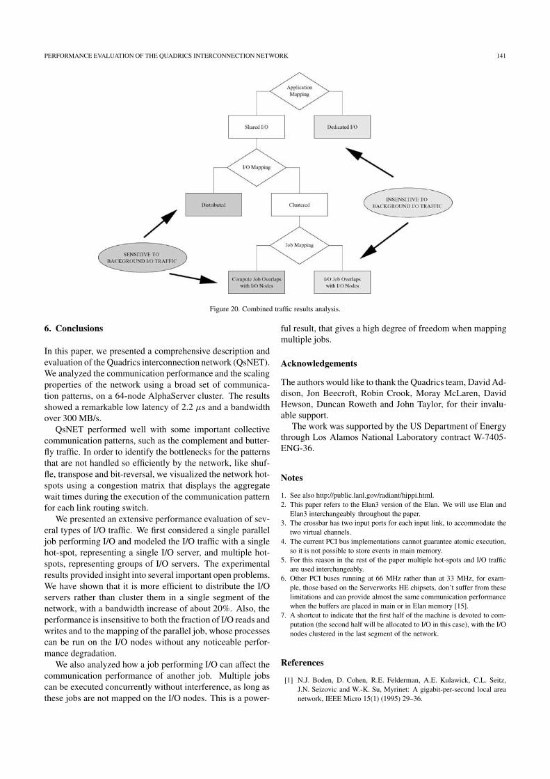
Figure 20 summarizes the analysis of the results and high-lights the performance regions where the computational jobis affected by the background I/O traffic.
PERFORMANCE EVALUATION OF THE QUADRICS INTERCONNECTION NETWORK 141
Figure 20. Combined traffic results analysis.
6. Conclusions
In this paper, we presented a comprehensive description andevaluation of the Quadrics interconnection network (QsNET).We analyzed the communication performance and the scalingproperties of the network using a broad set of communica-tion patterns, on a 64-node AlphaServer cluster. The resultsshowed a remarkable low latency of 2.2 µs and a bandwidthover 300 MB/s.
QsNET performed well with some important collectivecommunication patterns, such as the complement and butter-fly traffic. In order to identify the bottlenecks for the patternsthat are not handled so efficiently by the network, like shuf-fle, transpose and bit-reversal, we visualized the network hot-spots using a congestion matrix that displays the aggregatewait times during the execution of the communication patternfor each link routing switch.
We presented an extensive performance evaluation of sev-eral types of I/O traffic. We first considered a single paralleljob performing I/O and modeled the I/O traffic with a singlehot-spot, representing a single I/O server, and multiple hot-spots, representing groups of I/O servers. The experimentalresults provided insight into several important open problems.We have shown that it is more efficient to distribute the I/Oservers rather than cluster them in a single segment of thenetwork, with a bandwidth increase of about 20%. Also, theperformance is insensitive to both the fraction of I/O reads andwrites and to the mapping of the parallel job, whose processescan be run on the I/O nodes without any noticeable perfor-mance degradation.
We also analyzed how a job performing I/O can affect thecommunication performance of another job. Multiple jobscan be executed concurrently without interference, as long asthese jobs are not mapped on the I/O nodes. This is a power-
ful result, that gives a high degree of freedom when mappingmultiple jobs.
Acknowledgements
The authors would like to thank the Quadrics team, David Ad-dison, Jon Beecroft, Robin Crook, Moray McLaren, DavidHewson, Duncan Roweth and John Taylor, for their invalu-able support.
The work was supported by the US Department of Energythrough Los Alamos National Laboratory contract W-7405-ENG-36.
Notes
1. See also http://public.lanl.gov/radiant/hippi.html.2. This paper refers to the Elan3 version of the Elan. We will use Elan and
Elan3 interchangeably throughout the paper.3. The crossbar has two input ports for each input link, to accommodate the
two virtual channels.4. The current PCI bus implementations cannot guarantee atomic execution,
so it is not possible to store events in main memory.5. For this reason in the rest of the paper multiple hot-spots and I/O traffic
are used interchangeably.6. Other PCI buses running at 66 MHz rather than at 33 MHz, for exam-
ple, those based on the Serverworks HE chipsets, don’t suffer from theselimitations and can provide almost the same communication performancewhen the buffers are placed in main or in Elan memory [15].
7. A shortcut to indicate that the first half of the machine is devoted to com-putation (the second half will be allocated to I/O in this case), with the I/Onodes clustered in the last segment of the network.
References
[1] N.J. Boden, D. Cohen, R.E. Felderman, A.E. Kulawick, C.L. Seitz,J.N. Seizovic and W.-K. Su, Myrinet: A gigabit-per-second local areanetwork, IEEE Micro 15(1) (1995) 29–36.

142 PETRINI ET AL.
[2] H. Chen and P. Wyckoff, Simulation studies of Gigabit Ethernet versusMyrinet using real application cores, in: Proceedings of CANPC’00,Workshop of High-Performance Computer Architecture, Toulouse,France, January 2000.
[3] W.J. Dally and C.L. Seitz, Deadlock-free message routing in multi-processor interconnection networks, IEEE Transactions on ComputersC-36(5) (1987) 547–553.
[4] J. Duato, S. Yalamanchili and L. Ni, Interconnection Networks: AnEngineering Approach (IEEE Computer Society Press, 1997).
[5] A. Geist, W. Gropp, S. Huss-Lederman, A. Lumsdaine, E. Lusk,W. Saphir, T. Skjellum and M. Snir, MPI-2: Extending the mes-sage passing interface, in: 2nd International Euro-Par Conference,Lyon, France, Vol. 1, Lecture Notes in Computer Science, Vol. 1123(Springer, 1996) pp. 128–135.
[6] S. Heller, Congestion-free routing on the CM-5 data router, in: 1st In-ternational Workshop, PCRCW’94, Seattle, Washington, USA, LectureNotes in Computer Science, Vol. 853, eds. K. Bolding and L. Snyder(Springer, 1994) pp. 176–184.
[7] H. Hellwagner, The SCI standard and applications of SCI, in: SCI:Scalable Coherent Interface, Lecture Notes in Computer Science,Vol. 1291, eds. H. Hellwagner and A. Reinfeld (Springer, 1999) pp. 95–116.
[8] InfiniBand Specification 1.0a. InfiniBand Trade Association (June2001).
[9] D. Kerbyson, H. Alme, A. Hoisie, F. Petrini, H. Wasserman and M. Git-tings, Predictive performance and scalability modeling of a large-scale application, in: Supercomputing 2001, Denver, CO, November2001.
[10] C.E. Leiserson, Fat-trees: Universal networks for hardware efficient su-percomputing, IEEE Transactions on Computers C-34(10) (1985) 892–901.
[11] L.M. Ni, Y. Gui and S. Moore, Performance evaluation of switch-basedwormhole networks, IEEE Transactions on Parallel and DistributedSystems 8(5) (1997) 462–474.
[12] F. Petrini, Communication performance of wormhole interconnectionnetworks, Ph.D. thesis, Università degli Studi di Pisa, Dipartimento diInformatica, February 1997.
[13] F. Petrini, W. Chun Feng, A. Hoisie, S. Coll and E. Frachtenberg, Thequadrics network: High performance clustering technology, IEEE Mi-cro 22(1) (January–February 2002) 46–57.
[14] F. Petrini, S. Coll, E. Frachtenberg and A. Hoisie, Hardware- andsoftware-based collective communication on the Quadrics network, in:IEEE International Symposium on Network Computing and Applica-tions 2001 (NCA 2001), Boston, MA, October 2001.
[15] F. Petrini, A. Hoisie, W. Chun Feng and R. Graham, Performance eval-uation of the quadrics interconnection network, in: Workshop on Com-munication Architecture for Clusters (CAC’01), San Francisco, CA,April 2001.
[16] F. Petrini and M. Vanneschi, k-ary n-trees: High performance networksfor massively parallel architectures, in: Proceedings of the 11th Inter-national Parallel Processing Symposium, IPPS’97, Geneva, Switzer-land, April 1997, pp. 87–93.
[17] F. Petrini and M. Vanneschi, Performance analysis of wormhole routedk-ary n-trees, International Journal on Foundations of Computer Sci-ence 9(2) (June 1998) 157–177.
[18] G.F. Pfister and V.A. Norton, Hot-spot contention and combining inmultistage interconnection networks, IEEE Transactions on ComputersC-34(10) (1985) 943-948.
[19] Quadrics Supercomputers World Ltd., Elan Programming Manual (Jan-uary 1999).
[20] Quadrics Supercomputers World Ltd., Elan Reference Manual (January1999).
[21] Quadrics Supercomputers World Ltd., Elite Reference Manual (No-vember 1999).
[22] R. Seifert, Gigabit Ethernet: Technology and Applications for HighSpeed LANs (Addison-Wesley, 1998).
[23] M. Snir, S. Otto, S. Huss-Lederman, D. Walker and J. Dongarra, MPI –The Complete Reference, The MPI Core, Vol. 1 (The MIT Press, 1998).
[24] D. Tolmie, T.M. Boorman, A. DuBois, D. DuBois, W. Feng andI. Philp, From HiPPI-800 to HiPPI-6400: A changing of the guard andgateway to the future, in: Proceedings of the 6th International Confer-ence on Parallel Interconnects (PI’99), October 1999.
[25] W. Vogels, D. Follett, J. Hsieh, D. Lifka and D. Stern, Tree-saturationcontrol in the AC3 velocity cluster, in: Hot Interconnects 8 (StanfordUniversity, Palo Alto CA, 2000).
Fabrizio Petrini is a member of the technical staff of the CCS3 groupof the Los Alamos National Laboratory (LANL). His research interests in-clude performance evaluation, job scheduling algorithms, high performanceinterconnection networks and network interfaces, simulation of parallel ar-chitectures and operating systems. He was the recipient of the EuropeanCommunity Marie Curie Fellowship in 1997, and the Los Alamos Perfor-mance Award and The National Nuclear Security Agency (NNSA) Excel-lence Award, both in 2002.E-mail: [email protected]
Eitan Frachtenberg is a research assistant at Los Alamos National Labora-tory and a graduate student at Hebrew University of Jerusalem, Israel. Hisresearch interests include operating systems, networks and data compression.Frachtenberg has an M.S. in computer science and mathematics from the He-brew University of Jerusalem. He is a member of the IEEE.E-mail: [email protected]
Adolfy Hoisie is a staff scientist and the Leader of the Modeling, Algorithmsand Informatics Group in the Computer and Computational Sciences Divi-sion at the Los Alamos National Laboratory. His research interests includeperformance analysis and modeling, distributed computing and parallel com-puter architectures. He is a member of the IEEE.E-mail: [email protected]
Salvador Coll is a faculty member of electronic engineering at the TechnicalUniversity of Valencia, Spain. His research interests are in multicomputersystems and interconnection networks, with special interest in routing algo-rithms and collective communications. Coll has a B.S. in electronic engi-neering and an M.S. in computer science from the Technical University ofValencia. He is a member of the Spanish Academy of Engineering and theIEEE Computer Society.E-mail: [email protected]